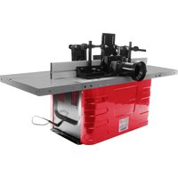
TFM610V_230V - Milling machine Holzmann - Free user manual and instructions
Find the device manual for free TFM610V_230V Holzmann in PDF.


| Product type | Table router (wood router) |
| Brand | Holzmann |
| Model | TFM610V_230V |
| Supply voltage | 230 V / 50 Hz / 1~ |
| Recommended fuse | 16 A |
| Residual current device | 30 mA (RCD) |
| Number of speeds | 6 |
| Speed range | 11,500 - 24,000 min⁻¹ |
| Router bit shank diameter | 6, 8 or 12 mm |
| Dust extraction connection | Yes (min. flow 800 m³/h) |
| Safety device | Transparent protective cover, emergency stop |
| Routing fence | Yes, adjustable |
| Table extension | Yes, with miter fence |
| Workpiece clamp and pressure bars | Yes |
| Spindle height adjustment | By handwheel |
| Machinable materials | Wood, plastic (not metal or stone) |
| Maintenance | Cleaning after use, acid-free lubrication |
| Warranty | 2 years (non-commercial), 1 year (commercial) |
| Spare parts | Available on Holzmann website |
Frequently Asked Questions - TFM610V_230V Holzmann
Tie back long hair.
User questions about TFM610V_230V Holzmann
0 question about this device. Answer the ones you know or ask your own.
Ask a new question about this device
Download the instructions for your Milling machine in PDF format for free! Find your manual TFM610V_230V - Holzmann and take your electronic device back in hand. On this page are published all the documents necessary for the use of your device. TFM610V_230V by Holzmann.
USER MANUAL TFM610V_230V Holzmann
natural_image
Red Hohmann industrial machine with mechanical components and mounting base (no visible text or symbols)
TFM610V_230V
CE
YOUR
JOB.
OUR
TOOLS.
1 INHALT / INDEX
1 INHALT/INDEX 2
12.1 Intended use of the machine....22
12.1.1 Technical restrictions.... 22
12.1.2 Prohibited applications / Dangerous misuse....22
12.2 User requirements....22
12.3 General safety instructions 22
12.4 Electrical safety....23
12.5 Special safety instructions for this machine....24
12.6 Hazard warnings....24
13 TRANSPORT 24
14 ASSEMBLY 25
14.1 Preparatory activities....25
14.1.1 Check delivery content....25
14.1.2 The workplace 25
14.1.3 Required connection at workplace....25
14.1.4 Electrical connection 25
14.1.5 Connection to dust collection system 25
14.2 Assembling the machine....26
15 OPERATION 28
15.1 Operating instructions....28
15.2 Starting / stopping the machine....29
15.3 Operation....29
16 CLEANING, MAINTENANCE, STORAGE, DISPOSAL 29
16.1 Cleaning 29
16.2 Maintenance....30
16.2.1 Tool exchange (collet and milling cutter)....30
16.3 Storage....31
16.4 Disposal....31
17 TROUBLESHOOTING 31
18 PRÓLOGO (ES) 32
19 SEGURIDAD....33
30.2 Maintenance....53
30.4 Élimination....55
31 RESOLUTION DE PANNE 55
32 PŘEDMLUVA (CZ) 56
33 BEZPEČNOST 57
EN EC-CONFORM: This product complies with the EC-directives.
EN Operation with gloves forbidden!
EN No open flame, fire, open source of ignition and smoking prohibited.
natural_image
Four circular icons representing safety and equipment symbols: boot, helmet, gear, and person (no text or labels)EN Wear personal protective equipment!
EN Switch off the machine before maintenance and breaks and pull out the mains plug.
EN Warning of pointed (sharp) tool
EN Missing or non-readable security stickers have to be replaced immediately.
| Beschreibung / Description | Beschreibung / Description | ||
| 1 | Druckleiste front / pressure pad front / Barra de presión frontal / Barre de pression frontale / Přítlačná lišta přední | 9 | Absauganschluss / dust collection port / Conexión del sistema de aspiración / Raccord d'aspiration / Připojení odsávání |
| 2 | Maschine / machine / Máquina / Machine / Stroj | 10 | Fräsanschlag / milling stop / Tope de fresado / Butée de toupillage / Frézovací pravítko |
| 3 | Thermoschalter / thermoswitch / Interruptor térmico / Interrupteur thermique / Termospínač | 11 | Gehrungsanschlag Miter gauge / Tope de ingletes / Butée à onglet / Úhlové pravítko |
| 4 | EIN-AUS-SCHALTER / ON-OFF-switch / INTERRUPTOR ON/OFF / INTERRUPTEUR MARCHE-ARRÊT / Hlavní vypínač | 12 | Niederhalter / down holder / Pisadores / Serre-flan / Přítlačný držák |
| 5 | Drehzahlregler Spindel / spindle speed control / Regulador de velocidad del husillo / Régulateur de vitesse de rotation de la broche / Regulace otáček vřetene | 13 | Druckleiste Oben / pressure pad top / Barra de presión superior / Barre de pression supérieure / Přítlačná lišta horní |
| 6 | Höhenverstellrad Spindel / spindle height adjustment wheel / Rueda de ajuste en altura del husillo / Volant de réglage de la hauteur de la broche / Ruční kolo výškového nastavení vřetene | 14 | Tischeinlageringe / table ring inlays / Anillos para el suplemento de la mesa / Plaques annulaires de platine / Kroužky vložky stolu |
| 7 | Klemmschraube Höhenverstellung / fixation knob height adjustment / Tornillo de fijación del ajuste en altura / Vis de serrage de réglage en hauteur / Upínací šroub výškového nastavení | 15 | Schaftfräseraufnahme / shank router cutter adapter / Alojamiento de la fresa de vástago / Logement de fraise à queue / Upínací pouzdro stopkové frézy |
| 8 | Verlängerungstisch / extension table / Mesa de extensión / Prolongement de table / Prodloužení stolu |
natural_image
Two technical diagrams showing a mechanical component labeled A and B/C, with no visible text or symbols beyond labels.natural_image
Close-up of mechanical components with labeled parts A, B, and C (no text or symbols beyond labels)natural_image
Mechanical assembly diagram showing a black bracket with labeled points A and B, no readable text or symbols present.natural_image
Close-up of a black electrical switch panel with a yellow arrow pointing to it (no visible text or symbols)A
natural_image
Close-up of mechanical components including a bolt, hexagonal nut, and circular housing (no text or symbols visible)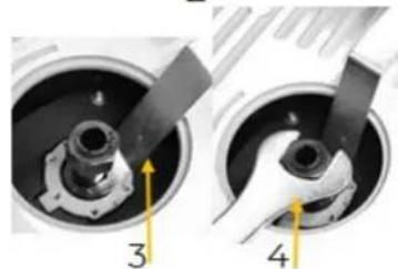
natural_image
Close-up of mechanical components in two views (labeled 3 and 4), showing internal parts with no visible text or symbols.This manual contains information and important notes for safe commissioning and handling of the table router TFM610V_230V, hereinafter referred to as "machine" in this document.

This manual is part of the machine and must not be removed. Save it for later reference and if you let other people use the machine, add this manual to the machine.
Please pay special attention to the chapter safety!
Before first use read this manual carefully. It eases the correct use of the machine and prevents misunderstanding and damages of machine.
Due to constant advancements in product design, construction, illustrations and contents may deviate slightly. If you notice any errors, please inform us.
We reserve the right to make technical changes!
Check the goods immediately after receipt and note any complaints on the consignment note when taking over the goods from the deliverer!
Transport damage must be reported to us separately to us within 24 hours.
HOLZMANN MASCHINEN GmbH cannot accept any liability for transport damage that has not been reported.
Copyright
© 2024
This documentation is protected by copyright. All rights reserved! In particular, the reprint, translation and extraction of photos and illustrations will be prosecuted.
The place of jurisdiction is the regional court Linz or the court responsible for 4170 Haslach is valid.
Customer service contact
This section contains information and important notes on the safe commissioning and handling of the machine.

For your safety, read this manual carefully before commissioning. This will enable you to handle the machine safely and thus prevent misunderstandings as well as personal injury and damage to property. Pay special attention to the symbols and pictograms used on the machine as well as the safety information and danger warnings!
12.1 Intended use of the machine
The machine is intended exclusively for the following activities:
Machining of wood and plastic materials such as: milling of grooves, machining of recesses, Copying of curves and lettering within the specified machine limits.
NOTE

HOLZMANN MASCHINEN GmbH assumes no responsibility or warranty for any other use or use beyond this and for any resulting damage to property or injury.
12.1.1 Technical restrictions
The machine is designed for the work under the following conditions:
Relative humidity max. 65 %
Temperature (operation) +5 °C to +40 °C
Temperature (storage, transport) -20 °C to +55 °C
12.1.2 Prohibited applications / Dangerous misuse
- Operating the machine without adequate physical and mental aptitude
- Operating the machine without knowledge of the operating instructions
• Changes in the design of the machine - Operating the machine in a potentially explosive environment (machine can generate ignition sparks during operation)
- Operation of the machine in closed rooms without chip and dust extraction (a normal household vacuum cleaner is not suitable as an extraction device).
- Operating the machine outside the limits specified in this manual
- Remove the safety markings attached to the machine.
- Modify, circumvent or disable the safety devices of the machine.
- Machining of metal and stone etc.
The non-intended use or the disregard of the explanations and instructions described in this manual will result in the expiration of all warranty claims and compensation claims for damages against HOLZMANN MASCHINEN GmbH.
12.2 User requirements
The physical and mental suitability as well as knowledge and understanding of the operating instructions are prerequisites for operating the machine. Persons who, because of their physical, sensory or mental abilities or their inexperience or ignorance, are unable to operate the machinery safely must not use it without the supervision or instruction by a responsible person.
Please note that local laws and regulations may stipulate the minimum age of the operator and restrict the use of this machine!
Put on your personal protective equipment before working on the machine.
Work on electrical components or equipment may only be carried out by a qualified electrician or under the instructions and supervision of a qualified electrician.
12.3 General safety instructions
To avoid malfunctions, damage and health impairments when working with the machine, the following points must be observed in addition to the general rules for safe working:
• Before commissioning, check the machine for completeness and function.
- Choose a level, vibration-free, non-slip surface for the installation location.
- Ensure sufficient space around the machine!
- Ensure sufficient lighting conditions at the workplace to avoid stroboscopic effects!
• Only use perfect tools that are free of cracks and other defects (e.g. deformations).
- Remove setting tools from the machine before switching on.
- Keep the area around the machine free of obstacles (e.g. dust, chips, cut workpiece parts etc.).
- Check the strength of the machine connections before each use.
- Never leave the running machine unattended. If necessary, stop the machine before leaving.
- The machine may only be operated, serviced or repaired by persons who are familiar with it and who have been informed of the dangers arising in the course of this work.
- Ensure that unauthorised persons maintain an appropriate safety distance from the machine and, in particular, keep children away from the machine.
- Wear suitable protective equipment (eye protection, dust mask, respiratory protection, ear protection, gloves when handling tools) as well as close-fitting work protective clothing - never wear loose clothing, ties, jewellery, etc. - danger of being drawn in!
• Work with gloves on rotating parts is not permitted!
- Hide long hair under hair protection.
- Do not remove any sections or other parts of the workpiece from the cutting area while the machine is running!
- Do not remove splinters and chips by hand! Use a sliding stick for this purpose!
• Always work with care and the necessary caution and never use excessive force.
- Do not overload the machine!
- Do not work on the machine if you are tired, not concentrated or under the influence of medication, alcohol or drugs!
- Do not use the machine in areas where vapours from paints, solvents or flammable liquids represent a potential danger (danger of fire or explosion!).
- Do not smoke in the immediate vicinity of the machine (fire hazard)!
- Make sure that the ON/OFF switch is in the "OFF" position before connecting the machine to the power source.
- Do not use the machine if it cannot be switched on and off with the ON/OFF switch.
• Make sure that the device is earthed.
• Only use suitable extension cords.
- Always shut down the machine before carrying out any conversion, adjustment, measuring, cleaning, maintenance or repair work and always disconnect it from the power supply for maintenance or repair work. Before starting any work on the machine, wait until all tools or machine parts have come to a complete standstill and secure the machine against unintentional restarting.
12.4 Electrical safety
• Make sure that the machine is earthed.
- Only use suitable extension cords.
- There is an increased risk of electric shock if your body makes contact with the ground. Avoid body contact with grounded objects, e.g. pipes, radiators, etc.
- A damaged or tangled cable increases the risk of electric shock. Handle the cable with care. Never use the cable to carry, pull or disconnect the power tool. Keep the cable away from heat, oil, sharp edges or moving parts.
• Proper plugs and sockets reduce the risk of electric shock.
- Water entry into machine increases the risk of electric shock. Do not expose machine to rain or moisture.
- The machine may only be used in humid environments if the power source is protected by a residual current circuit breaker.
- Do not use the machine if it cannot be turned on and off with the ON/OFF switch.
12.5 Special safety instructions for this machine
- During operation of the machine wood dust is generated. Therefore, connect the machine to a suitable dust collection system for dust and chips during installation!
• Always switch on the dust collection system before you start machining the workpiece! - When using milling tools with a diameter of ≥ 16 mm and circular saw blades, these must comply with EN 847-1:2013 and EN 847-2:2013; tool carriers must comply with EN 847-3:2013;
- Excessive noise can cause hearing damage and temporary or permanent hearing loss. Wear hearing protection certified to health and safety regulations to limit noise exposure.
- Before putting the machine into operation, check that the milling tool is firmly seated and concentric!
- Do not use damaged tools (milling cutters) and ensure that the maximum speed of the milling cutter is above the maximum speed of the machine and that the shank diameter of the milling cutter is within the limits specified for the machine.
- When operating the machine, make sure that metal parts, screws, nails, etc. never gets in contact with the cutter and if greater milling depths are requested use several stages for producing to avoid damaging of the machine and tool.
- Allow the machine to reach full speed and then immerse the cutter in the workpiece.
- If the cutter is clogged with waste, stop the machine. Allow the cutter to run out completely. Remove the waste with a longer rod and not with your fingers.
- Allow the cutter to run out completely before removing the workpiece.
- The milling must always be carried out against the direction of rotation (counter-rotation) of the milling cutter.
12.6 Hazard warnings
Despite intended use, certain residual risk factors remain. Due to the structure and construction of the machine, hazardous situations may occur which are identified in this manual as follows:
DANGER

A safety instruction designed in this way indicates an imminently hazardous situation which, if not avoided, will result in death or serious injury.
WARNING

A safety instruction designed in this way indicates a potentially hazardous situation which, if not avoided, could result in death or serious injury.
CAUTION

A safety instruction designed in this way indicates a possibly hazardous situation which, if not avoided, may result in minor or moderate injury.
NOTE

A safety notice designed in this way indicates a potentially hazardous situation which, if not avoided, may result in property damage.
Regardless of all safety regulations, your common sense and your appropriate technical aptitude/training are and remain the most important safety factors in the error-free operation of the machine. Safe working depends on you!
13 TRANSPORT
To ensure proper transport, also observe the instructions and information on the transport packaging regarding centre of gravity, attachment points, weight, means of transport to be used and the prescribed transport position, etc.
Transport the machine in its packaging to the place of installation. When lifting, carrying and depositing the load, ensure the correct posture:
Lifting / Setting down
- When lifting/setting down, ensure that you are standing firmly (legs hip-width apart).
- Lift/set down load with knees bent and back straight.
- Do not lift/set down load with a jerk.
Carrying
- Carry load with both hands as close to body as possible.
- Carry load with straight back.
When transporting the assembled machine, ensure to lift it only by the machine body and not by the attachments. If you transport the machine with a vehicle, ensure that the load is secured appropriately!
14 ASSEMBLY
14.1 Preparatory activities
14.1.1 Check delivery content
Check the machine immediately after delivery for transport damage and missing parts.
14.1.2 The workplace
The floor at the installation site must be able to support the weight of the machine. The minimum space required for the machine is determined by the dimensions of the machine plus a safety area of approx. 80 cm around the machine.
Choose a level, load-bearing surface with adequate space for the machine. The installation site must also meet the ergonomic requirements of a workplace.
14.1.3 Required connection at workplace
WARNING
Dangerous electrical voltage! The machine may only be connected to the mains supply and the associated checks carried out by a qualified electrician or under the instruction and supervision of a qualified electrician!
The machine is operated with alternating current (230 V, 1\~, 50 Hz). The use of 16 A fuses is recommended.
14.1.4 Electrical connection
To connect the machine to the electrical mains, proceed as follows:
- Check that the supply voltage and the current frequency correspond to the specifications of the machine (refer to technical data or type-plate).
• Use a suitable device to check that the earthing are working properly. - The power supply circuit must be equipped with overvoltage protection (RCD with maximum residual current of 30 mA).
- For the required cross-section of the supply cables, please refer to the current carrying capacity table. (Make sure that the cables are in good condition and suitable for power transmission. Undersized cables reduce the power transmission and heat up considerably.)
- Connect the appliance plug to the socket provided for this purpose.
14.1.5 Connection to dust collection system
NOTE

The dust collection system must start at the same time as the motor of the machine. In addition, the dust collection system must guarantee an output of at least 800 m^3/h .
14.2 Assembling the machine
The machine is pre-assembled, the parts removed for transport must be assembled according to the following instructions and the connection to mains have to be made.
| Assembly milling stop | ||
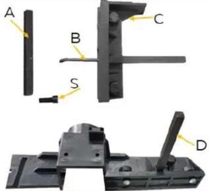 | 1. Assembly support rods (x2) for downholderInsert the support rod into the holder of the milling stop (C; D) and fasten with the screw (S) using an Allen key (B). | |
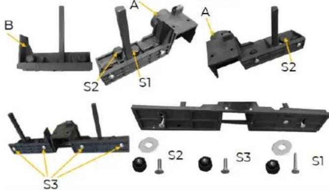 | 2. Assembly milling stopInsert part B into the grooves provided and fix it with screw S1. Insert the two screws S2 and insert the 4 screws S3 to fix the stops. | |
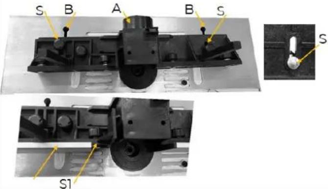 | 3. Mounting milling stop onto machineDie Insert the two screws (S) of the assembled milling stop into the slots (B) on the machine table and fix them. Then insert the slots of the milling stops (C) into the two screws (S1) and fix them with a knob. | |
| Assembly protective hood | ||
 | Place the protective hood (C) on the holder (A) on the milling stop and fasten it to it using the bolt (B). The transparent protective cover protects you from possible contact with the milling cutter. Check whether the protection can be folded down and is securely fastened.Your milling stop is now completely mounted. | |
Assembly pressure pad and downholder

Assembly height adjustment wheel
natural_image
Close-up of mechanical components labeled A, B, and C showing internal parts and a central knob (no text or symbols beyond labels)Assembly table extension
Assembly mitre gauge
natural_image
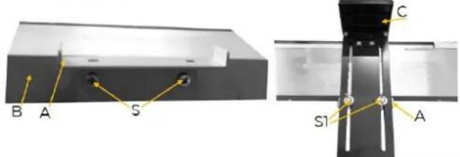
Mechanical assembly diagram showing two labeled components A and B with alignment tools (no text or symbols beyond labels)- Mount the upper pressure pad (A) with 2 screws (S), 2 washers at the stop (B) and the two retaining rods (F) for the hold-down devices (E) to the retaining rods (C) using clamps (D).
- The hold-down devices (E) can then be fastened to the holder (E) using screws (S1).
NOTE

In order to mount the pressure pad, the protective hood must first be dismantled.
- Fasten the bracket (A) to the machine table (B) with screws (S).
- Fasten the pressure pad (C) to the bracket using screws (S1).
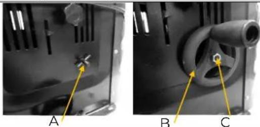
Place the handwheel (B) on the cotter pin+bolt (A) and secure with nut C.
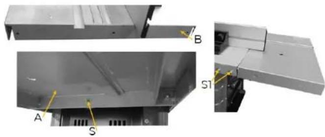
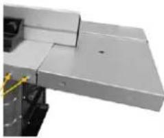
Mount the table extension (A) to the machine table (B) using 3 screws, washers (S) below and 2 screws/nuts/washers (S1) each on the right and left side.
NOTE

The table extension can be adapted to the groove on the main table and finally fixed in the appropriate position with the screw S to be able to work with the mitre gauge.
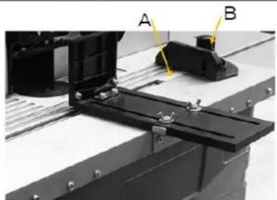
Insert the guideway of the mitre gauge (A) into the groove on the table and fix the mitre gauge in position (angle+position) by tightening the screw (B).
Mounting of the machine at the workplace:
Fix the machine to a workbench using the four holes on the base of the machine.
NOTE

The bolts must be sufficiently long (taking into account the thickness of the work surface, washers/nuts). The working top must be sufficiently large and stable to prevent the machine from tilting during operation.
15 OPERATION
15.1 Operating instructions
Installing and Changing the shank router cutter adapter.
CAUTION

Before any manual handling of the machine, stop the spindles, wait for all tools to come to a standstill and prevent unintentional restarting (pull out the mains plug).
Before changing the shank router cutter adapter, disconnect the mains plug of your machine. Select the adapter that corresponds exactly to the diameter of your milling cutter/tool.
Remove the table inlet rings to gain access to the spindle. Lock the spindle in place with the knob located at the bottom of the spindle. Loosen the lock nut of the clamp using the supplied wrench. Insert or remove the clamp located in the nut. Tighten the clamp nut firmly while holding the spindle in place. Before each use of the machine, make sure that the milling tool is securely clamped at the end of the spindle. Insert the appropriate table insert rings (depending on the selected milling tool). Adjust the stop as required and connect to a dust collection system. Reconnect the machine to the mains.
Adjusting the stop
Each work must be considered separately.
For each new use, make sure that the guards are properly installed and adjusted. With each new use, each pressure piece on the stop must be readjusted.
Make sure that each screw is well tightened before you start milling.
Usage of the table insert rings
The table insert rings must be used to reduce the distance between the table and the spindle to a minimum. Before switching on the machine, you must systematically check that the supplied table rings are correctly installed. Check that you have selected the appropriate table ring for the milling tool and its installation height to reduce the risk of tilting of the workpiece when passing through the hole. The table ring must surround the cutter as far as possible
Adjusting the spindle speed
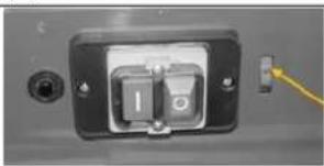
The machine has 6 steps for adjusting the spindle speed, desired speed and can be selected by wheel (A).
natural_image
Close-up of a black electrical outlet switch with a yellow cable inserted (no visible text or symbols)A
Spindle speed f (steps)
Determine the optimum speed by making a test cut on a sample piece. The table on the machine serves as a guideline. The first column in the table shows the cutting speed depending on the selected milling diameter and spindle speed. In the second column there is a recommendation of the speed to be selected as a function of the milling diameter and type of wood.
| 20 | 12 | 14 | 16 | 19 | 22 | 25 |
| 40 | 24 | 27 | 32 | 38 | 44 | 50 |
| 50 | 30 | 34 | 41 | 47 | 55 | 63 |
| n(min-1) | 11500 | 13000 | 15500 | 18000 | 21000 | 24000 |
| material | Cutting tool ø mm | rpm-selection |
| Hardwood (eg beech, yew) | 4-10 | 5-6 |
| 12-20 | 3-5 | |
| 22-40 | 1-2 | |
| softwood (eg spruce, pine) | 4-10 | 5-6 |
| 12-20 | 3-6 | |
| 22-40 | 1-3 |
NOTE

Using the correct speed increases the service life of the milling cutter. It also affects the machined surface on the part.
Adjusting the milling stop
The stop must be adjusted to the size of the workpiece and the milling tool.
Loosen the two plastic screws on the back of the stop.
Push the stop into the desired position.
Retighten the two plastic head screws on the back to hold the stop in this position.
Setting the stop for rabbit cuts
The material coming out to the left of the router is thinner than the material on the right. The left stop bar must be adjusted to fit the thinner material. This supports the material and ensures a more accurate cut. To do this, loosen the plastic head screws, move the stop forward and clamp it in place.
Installing and adjusting the pressure pads
The pressure pads are designed to hold the workpiece in place and prevent recoil.
Adjusting the miter gauge
The miter gauge slides in the groove along the table. It is used to make rabbit and miter cuts. To set the miter fence to the desired angle, loosen the plastic knob on it and turn it to the desired angle. Then tighten it again.
Always make a test cut on a sample piece to make sure that the settings are correct.
15.2 Starting / stopping the machine
Start procedure
- Adjusting the machine (spindle speed, cutting tool, spindle height, pressure pads, stops) for upcoming operation.
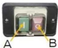
- Press green-button (A) for start.
Stopp procedure
- Press red-button (B) for stopping the machine.
15.3 Operation
Assembly and secure the cutter tool.
- Adjust speed, cutting depth, pressure pads, stop and mitre gauge.
- Make sure that the stop is correctly adjusted to support the material which is actual not cut. Adjust the output stop to support the cut material, compensating for the material removed.
- Start the machine.
• Make sure that the workpiece is pressed firmly against the stop.
- Slide the workpiece softly from right to left against the direction of rotation of the tool.
- Keep the feed speed constant. Do not push too fast, this would slow down the motor too much.
- If you push too fast, you may achieve poor cut quality. It could also damage the cutter or the motor.
• If you push too slowly, fire marks may appear on the workpiece.
- With very hard wood and large cuts, it may be necessary to do more than one operation to achieve the desired depth.
- The correct feed speed depends on the cutter size, the type of material of the workpiece and the cutting depth. Practice first with a piece of waste material to find the correct feed rate and dimensions.
- When the operation is complete, stop the machine.
16 CLEANING, MAINTENANCE, STORAGE, DISPOSAL
16.1 Cleaning
NOTE

Incorrect cleaning products can attack the finish of the machine. Do not use any solvents, nitro thinners or other cleaning products that could damage the machine's finish.
Observe the specifications and instructions of the cleaning agent manufacturer.
Regular cleaning is a prerequisite for the safe operation of the machine and its long service life.
- Therefore, clean the machine after each use, but at least once a week and remove any sawdust with a brush, broom or vacuum cleaner.
16.2 Maintenance
WARNING

Handling the machine with the power supply up can lead to serious injuries or even death.
→ Always disconnect the machine from the power supply before servicing or maintenance work and secure it against unintentional or unauthorised reconnection!
The machine is low-maintenance and only a few parts have to be serviced. Nevertheless, malfunctions or defects which could impair the safety of the user must be rectified immediately!
• Before each operation, check that the safety devices are in perfect condition.
- Check the connections for tightness at least once a week.
- Regularly check that the warning and safety labels on the machine are in perfect and legible condition.
16.2.1 Tool exchange (collet and milling cutter)
CAUTION

Before any manual tool change, stop the spindles, wait for all tools to come to a standstill and prevent unintentional restart.
Collet (shank router cutter adapter)
natural_image
Exploded view of mechanical components including a flanged component, a circular housing, and a separate close-up of a mechanical part (no text or symbols visible)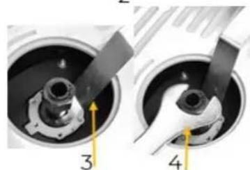
natural_image
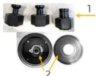
Close-up of mechanical components with numbered callouts (3 and 4), no visible text or symbolsSelect the collet ( 6 mm, 8 mm or 12 mm) that corresponds exactly to the diameter of your milling cutter (1). Move the spindle to the highest position using the handwheel.
Remove the table ring inlays (2) to gain access to the spindle.
Position the cranked open-end wrench on the flattened part of the spindle to lock it in place (3).
Loosen the locking nut of the collet chuck with the open-end wrench (4).
Remove the collet and insert the selected collet (1) into the spindle holder.
Tighten the collet nut firmly while holding the spindle in place (4).
Milling cutter
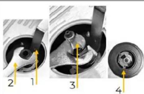
Position the cranked open-end wrench on the flattened part of the spindle to lock it in place (1).
Loosen the locking nut of the collet slightly with the open-end wrench (2).
Remove or insert the appropriate milling tool into the collet (3).
Tighten the collet nut (2) while fixing the spindle (1).
Depending on the milling cutter size, insert the table ring inlays to minimize the distance between the table and spindle (4).
16.3 Storage
NOTE

Improper storage can damage and destroy important components. Only store packed or already unpacked parts under the intended ambient conditions!
In case of a longer interruption of operation or shutdown, clean the machine and then store it out of the reach of children in a dry place protected from frost and other weather influences!
16.4 Disposal
Observe the national waste disposal regulations. Never dispose of the machine, machine components or operating equipment in the residual waste. If necessary, contact your local authorities for information regarding available disposal options.
If you purchase a new machine or equivalent equipment from your specialist dealer, he is obliged in certain countries to dispose of your old machine properly.
17 TROUBLESHOOTING
WARNING

Danger due to electrical voltage!
Handling the machine with connected power supply may result in serious injury or death.
→ Disconnect the machine from the power supply before starting work to eliminate defects!
Many possible sources of error can be excluded in advance if the machine is properly connected to the mains. If you are unable to carry out necessary repairs properly and/or do not have the required training, always consult a specialist to correct the problem!
| Trouble | Possible cause | Solution |
| Machine cannot be switched on | No mains voltage availableCarbon brushes worn out | repair switchcheck power supply, replace fuse or switch contactor if necessary |
| The machine switches off automatically during idling | Mains failure | Check mains-side fuseDue to undervoltage protection, the machine does not restart automatically and must be switched on again after voltage recovery. |
| Machine stops during machining | overload protection activated due to blunt tools or excessive feed or chip thickness | Before continuing work, replace the tool and wait for the motor to cool down. |
| Speed drops during machining | Too much chip removalFeed rate too highBlunt tool | Reduce chip removalDecrease feed rateReplace tool |
| Badly milling surface | Blunt toolUneven feed rate | Replace toolWork with reduce feed rate and constant pressure |
| Dust collector port clogs (without dust collection system) | Too much chip removalBlunt toolToo wet wood | Reduce chip removalReplace tool |
18 PRÓLOGO (ES)
Estimado cliente!
natural_image
Mechanical component with a lever and mounting bracket (no visible text or symbols)natural_image
3D mechanical assembly diagrams showing labeled parts A and B, with no readable text or symbols beyond labels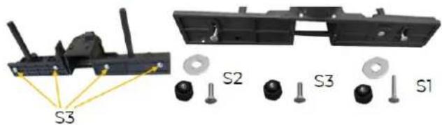
natural_image
Two technical diagrams showing a mechanical component and a transparent plastic structure, labeled A, B, and C (no text or symbols beyond labels)natural_image
Close-up of mechanical components labeled A, B, and C showing internal parts and a central pipe (no text or symbols beyond labels)natural_image
Mechanical assembly diagram showing a mechanical component with labeled points A and B (no text or symbols beyond labels)natural_image
Close-up of a black electrical switch with a yellow arrow pointing to it (no visible text or symbols)A
Cher client, chère cliente,
26.1.1 Restrictions techniques
natural_image
Mechanical component with a yellow arrow labeled 'D' pointing to a specific part (no text or symbols on the main structure)natural_image
Two technical diagrams showing a mechanical component and a transparent plastic structure, labeled A, B, and C (no text or symbols beyond labels)natural_image
Close-up of a mechanical component with labeled parts A, B, and C (no text or symbols beyond labels)natural_image
Mechanical assembly diagram showing two components labeled A and B, with no visible text or symbols beyond labelsnatural_image
Close-up of a black electrical outlet switch with a yellow arrow pointing to it, labeled 'A' (no text or symbols on the switch itself)natural_image
Close-up of a mechanical component with two circular parts, one showing internal structure and the other showing outer ring (no text or symbols)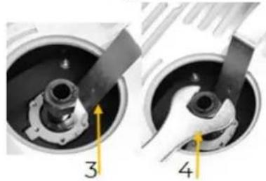
natural_image
Close-up of mechanical components with numbered callouts (3 and 4), no visible text or symbolsnatural_image
3D diagram of a mechanical component with labeled points A, B, and S (no text or symbols beyond labels)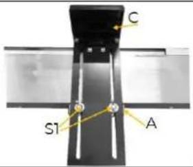
natural_image
Close-up of a black plastic panel with a yellow screwdriver inserted, no visible text or symbols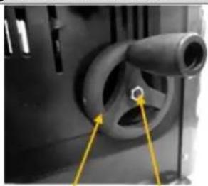
natural_image
Close-up of a mechanical component with a curved pipe and circular features, marked by yellow arrows (no visible text or symbols)B
C
natural_image
Two views of a mechanical or electronic component with labeled points A and S, showing internal structure and mounting features (no text or symbols beyond labels)3
natural_image
Close-up of a metallic mechanical component with no visible text or symbolsnatural_image
Mechanical assembly diagram showing a black bracket mounted on a metal frame with labeled points A and B (no text or symbols beyond labels)natural_image
Exploded view of a mechanical component showing internal parts and assembly (no text or symbols visible)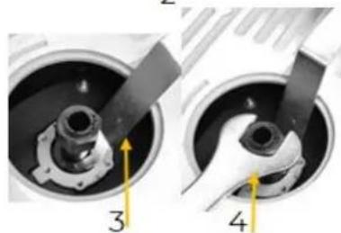
natural_image
Close-up of mechanical components with numbered callouts (3 and 4), no visible text or symbolsnatural_image
Close-up of a mechanical component with a yellow arrow and number 3, no visible text or symbols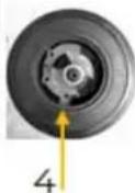
flowchart
graph TD
    A["230V/50Hz~"] --> B["brown"]
    B --> C["EMC"]
    C --> D["PCB"]
    D --> E["over current protector"]
    E --> F["power switch"]
    F --> G["1"]
    G --> H["blue"]
    H --> I["0"]
    I --> J["yellow and green"]
    J --> K["ground"]
    L["L"] --> M["abc"]
    N["N"] --> O["abc"]
    P["PE"] --> Q["abc"]
    R["PCB for speed adjustment"] --> S["SCR"]
    S --> T["R1"]
    S --> U["DZ"]
    S --> V["R2"]
    S --> W["p"]
    S --> X["speed adjustment"]
    Y["choice switch"] --> Z["K"]
    AA["blue"] --> AB["brown"]
    AC["motor"] --> AD["M"]
    AE["PCB"] --> AF["R1"]
    AE --> AG["DZ"]
    AE --> AH["R2"]
    AE --> AI["p"]
40 ERSATZTEILE / SPARE PARTS
PIEZAS DE RECAMBIO / PIÈCES DE RECHANGE / NÁHRADNÍ DÍLY
(EN) With original HOLZMANN spare parts you use parts that are attuned to each other shorten the installation time and elongate your products lifespan.
NOTE

The installation of parts other than original spare parts leads to the loss of the guarantee! Therefore: When replacing components/parts, only use spare parts recommended by the manufacturer.
Order the spare parts directly on our homepage – category SPARE PARTS or contact our customer service
- via our Homepage – category SERVICE – SPARE PARTS REQUEST,
• by e-mail to service@holzmann-maschinen.at.
Always state the machine type, spare part number and designation. To prevent misunderstandings, we recommend that you add a copy of the spare parts drawing with the spare parts order, on which the required spare parts are clearly marked, especially when not using the online-spare-part catalogue.
For mechanical and electrical components Company HOLZMANN MASCHINEN GmbH grants a warranty period of 2 years for DIY use and a warranty period of 1 year for professional/industrial use - starting with the purchase of the final consumer (invoice date).
In case of defects during this period which are not excluded by paragraph 3, Holzmann will repair or replace the machine at its own discretion.
2.) Report
In order to check the legitimacy of warranty claims, the final consumer must contact his dealer. The dealer has to report in written form the occurred defect to HOLZMANN MASCHINEN GmbH. If the warranty claim is legitimate, HOLZMANN MASCHINEN GmbH will pick up the defective machine from the dealer. Return shipments by dealers which have not been coordinated with HOLZMANN MASCHINEN GmbH will not be accepted. A RMA number is an absolute must-have for us - we won't accept returned goods without an RMA number!
3.) Regulations
a) Warranty claims will only be accepted when a copy of the original invoice or cash voucher from the trading partner of HOLZMANN MASCHINEN GmbH is enclosed to the machine. The warranty claim expires if the accessories belonging to the machine are missing.
b) The warranty does not include free checking, maintenance, inspection or service works on the machine. Defects due to incorrect usage through the final consumer or his dealer will not be accepted as warranty claims either.
c) Excluded are defects on wearing parts such as carbon brushes, fangers, knives, rollers, cutting plates, cutting devices, guides, couplings, seals, impellers, blades, hydraulic oils, oil filters, sliding jaws, switches, belts, etc.
d) Also excluded are damages on the machine caused by incorrect or inappropriate usage, if it was used for a purpose which the machine is not supposed to, ignoring the user manual, force majeure, repairs or technical manipulations by not authorized workshops or by the customer himself, usage of non-original Holzmann spare parts or accessories.
e) After inspection by our qualified staff, resulted costs (like freight charges) and expenses for not legitimated warranty claims will be charged to the final customer or dealer.
f) In case of defective machines outside the warranty period, we will only repair after advance payment or dealer's invoice according to the cost estimate (incl. freight costs) of HOLZMANN MASCHINEN GmbH.
g) Warranty claims can only be granted for customers of an authorized HOLZMANN MASCHINEN GmbH dealer who directly purchased the machine from HOLZMANN MASCHINEN GmbH. These claims are not transferable in case of multiple sales of the machine.
4.) Claims for compensation and other liabilities
The liability of company HOLZMANN MASCHINEN GmbH is limited to the value of goods in all cases.
Claims for compensation because of poor performance, lacks, damages or loss of earnings due to defects during the warranty period will not be accepted.
HOLZMANN MASCHINEN GmbH insists on its right to subsequent improvement of the machine.
SERVICE
After Guarantee and warranty expiration specialist repair shops can perform maintenance and repair jobs. But we are still at your service as well with spare parts and/or product service. Place your spare part/repair service cost inquiry by
• mail to service@holzmann-maschinen.at,
• or use the online complaint order formula provided on our homepage-category service.
(EN) We monitor the quality of our delivered products in the frame of a Quality Management policy.
Your opinion is essential for further product development and product choice. Please let us know about your:
- Impressions and suggestions for improvement.
- Experiences that may be useful for other users and for product design
- Experiences with malfunctions that occur in specific operation modes
We would like to ask you to note down your experiences and observations and send them to us via e-mail or by post:

- INHALT / INDEX
- Please pay special attention to the chapter safety!
- Copyright
- Customer service contact
- Intended use of the machine
- NOTE
- Technical restrictions
- Prohibited applications / Dangerous misuse
- User requirements
- Please note that local laws and regulations may stipulate the minimum age of the operator and restrict the use of this machine!
- General safety instructions
- Electrical safety
- Special safety instructions for this machine
- Hazard warnings
- DANGER
- WARNING
- CAUTION
- TRANSPORT
- Lifting / Setting down
- Carrying
- ASSEMBLY
- Preparatory activities
- Check delivery content
- The workplace
- Required connection at workplace
- Electrical connection
- Connection to dust collection system
- Assembling the machine
- Assembly pressure pad and downholder
- Assembly height adjustment wheel
- Assembly table extension
- Assembly mitre gauge
- OPERATION
- Operating instructions
- Adjusting the stop
- Usage of the table insert rings
- Adjusting the spindle speed
- Adjusting the milling stop
- Setting the stop for rabbit cuts
- Installing and adjusting the pressure pads
- Adjusting the miter gauge
- Starting / stopping the machine
- Start procedure
- Stopp procedure
- Operation
- CLEANING, MAINTENANCE, STORAGE, DISPOSAL
- Cleaning
- Maintenance
- Tool exchange (collet and milling cutter)
- Collet (shank router cutter adapter)
- Milling cutter
- Storage
- Disposal
- TROUBLESHOOTING
- Danger due to electrical voltage!
- PRÓLOGO (ES)
- Estimado cliente!
- Cher client, chère cliente,
- Restrictions techniques
- ERSATZTEILE / SPARE PARTS
- PIEZAS DE RECAMBIO / PIÈCES DE RECHANGE / NÁHRADNÍ DÍLY
- 2.) Report
- 3.) Regulations
- 4.) Claims for compensation and other liabilities
- SERVICE
Brand : Holzmann
Model : TFM610V_230V
Category : Milling machine