ScreenBar Halo 2 - Lamp BENQ - Free user manual and instructions
Find the device manual for free ScreenBar Halo 2 BENQ in PDF.
User questions about ScreenBar Halo 2 BENQ
0 question about this device. Answer the ones you know or ask your own.
Ask a new question about this device
Download the instructions for your Lamp in PDF format for free! Find your manual ScreenBar Halo 2 - BENQ and take your electronic device back in hand. On this page are published all the documents necessary for the use of your device. ScreenBar Halo 2 by BENQ.
USER MANUAL ScreenBar Halo 2 BENQ
© 2025 BenQ Corporation.
All rights reserved. Rights of modification reserved.
Package Contents
The package should include the following items. If anything is missing or damaged, please contact the place of purchase immediately.
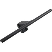
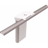
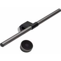
- 1 x ScreenBar Halo 2 lamp (with USB-C power cord)
- 1x Warranty information
- 1x Wireless controller
- 1x Power adapter
• 1 x Quick Start Guide
- 1x Webcam accessory

The illustrations in this guide are for your reference only and may look different from the actual product.
Safety Warnings
- Only use the supplied power adapter or a certified USB-C power adapter (5V DC, 3A or higher) with this lamp. Otherwise this lamp will not work properly and may even cause a fire.
- Do not place or hang any objects on this lamp, so as to avoid malfunction of this lamp.
- Route the USB-C power cord so as to avoid it from being pinched by items placed upon it or against it.
- If this lamp will not be used for an extended period of time, remove the USB-C power cord from the USB port and turn off the power of the wireless controller.
- This lamp is suitable for indoor use only.
-
The wireless controller of this lamp has a built-in rechargeable lithium battery. Pay special attention to the following matters when using this lamp:
-
Do not allow the wireless controller to be hit, dropped or placed in a high/low temperature environment (e.g., near a fire/heat source or in a closed car under the sun) to prevent the battery from being damaged or heated and causing a fire or explosion.
- If the wireless controller will not be used for a long period of time, charge it at least once a month or slide the power switch on the bottom of the wireless controller to OFF in order to avoid damage to the battery due to over-discharge.
- Rechargeable batteries are consumables and it is normal that their capacity will gradually decrease over time and with the number of times they are used.
- When travelling by air, remember to place this lamp in your carry-on baggage, not in checked baggage.
- This lamp is not suitable for USB-A port power supply. Insufficient power supply will cause the lamp to flicker.
- If this lamp is powered by a device other than the supplied power adapter, such as a monitor, laptop, desktop, USB hub, etc., it may be susceptible to an abnormality due to insufficient power supply. If this happens, use the supplied power adapter instead.

CAUTION
- If you encounter the following situations, please remove the USB-C power cord from the USB port immediately, and seek support from an authorized service agent or qualified technician:
- When the casing of this lamp is damaged
- When this lamp emits an abnormal smell
- When the LED light source flickers abnormally
-
When the power cord is damaged or the wire inside is exposed
-
Do not expose this lamp to humid environments (such as bathrooms, outdoors) to avoid short circuits and accidents.
- This lamp is only suitable for indoor use, do not use it outdoors.
- It is strictly prohibited to disassemble any part or component of this lamp. Otherwise it may cause an accident and invalidate the product warranty.
Assembly
Installing the Lamp
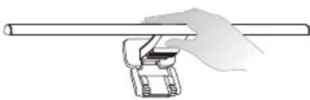
- Extend the clip of the lamp as shown in [Figure A]
- Rest the lamp on the monitor bezel [Figure B-1] recommended that you fit the clamp closely against the monitor bezel so there is no visible gap in between.

text_image
A B ① ② 0.43cm ~ 6cm- Connect the USB-C power cord to the supplied power adapter and plug it into a power outlet [Figure B 2]
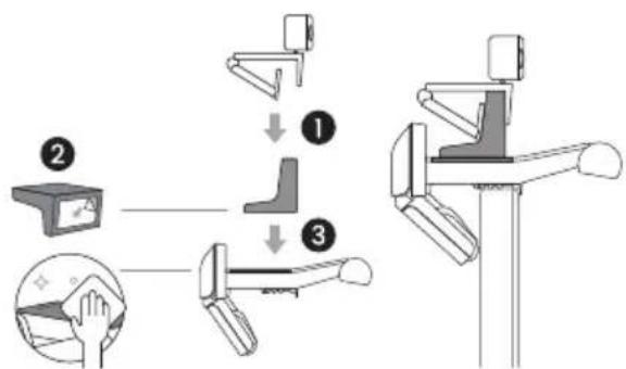
If your adapter includes multiple plugs, please refer to the installation instructions below.

flowchart
graph TD
    A["①"] --> B["②"]
    B --> C["③"]
    style A fill:#f9f,stroke:#333
    style B fill:#ccf,stroke:#333
    style C fill:#cfc,stroke:#333
- The thickness of the monitor frame must be within the range of 0.43 ~cm - 6 ~cm
- Refer to the illustrations below for how to install the lamp on different types of monitors:
Monitor with beveled bezel
Monitor with round bezel
Curved monitor Monitor with bulge on the back

natural_image
Line drawing of a wooden post with metal frame and support bracket (no text or symbols)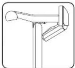
natural_image
Line drawing of a simple wooden post with a curved handle and vertical support (no text or symbols)
natural_image
Simple line drawing of a mechanical clamp or bracket (no text or symbols)
natural_image
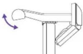
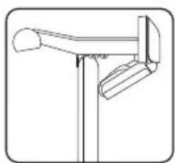
Line drawing of a mailbox with handle and spout (no text or symbols)- You can adjust the light to a suitable angle by rotating the lamp body.
natural_image
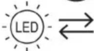
Diagram of a mechanical lever mechanism with directional arrows indicating motion (no text or symbols)- Slide the power switch on the bottom of the wireless controller to ON and tap the Power ⏻ button on the front of the wireless controller to begin using it.

text_image
ON I OFF ← ← ←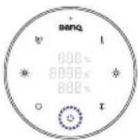
text_image
benq 000°C 000°C 000°C 000°C 000°C 000°C 000°CIf the wireless controller will not be used for a long period of time, slide the power switch on the bottom of the wireless controller to OFF.
Installing the Webcam Accessory
- Place the webcam on top of the webcam accessory.
- Remove the release paper from the adhesive tape on the underside of the webcam accessory.
- Clean the top surface of the clip and attach the accessory to the flat area in the middle of the clip.

• To remove the webcam accessory, hold the upper part of the accessory and pull it towards the light tube.
- To replace the adhesive tape, remove the current tape and use the spare adhesive tape provided in the box.
flowchart
graph TD
    A["Device Input"] --> B{Step 1}
    B --> C["Close-up of the device"]
    B --> D["Close-up of the device"]
    C --> E["Inserted position"]
    D --> F["Inserted position"]
Charging the Wireless Controller
Use a USB-C cable (not supplied) to connect the USB-C port on the wireless controller to the supplied power adapter or a certified USB-C port power supply (5V'DC/1A or higher) to start charging the wireless controller.
- When charging, the power indicator on the wireless controller will light up red.
- When fully charged, the power indicator will light up green.

- If the power indicator blinks red while the wireless controller is in use, the power level is too low. Charge the wireless controller as soon as possible.
- If the power indicator blinks red and green alternately during charging, it indicates abnormal charging. Use the supplied power adapter or replace the USB-C power cable. If the blinking persists, stop charging and seek support from an authorized service dealer or qualified technician.
- The wireless controller is not recommended to be charged from a USB-A port. Insufficient power supply will cause the power indicator to blink.
- Connect the wireless controller to a USB-C port that provides more than 5V DC/1A power to ensure proper charging.
- The wireless controller cannot be used as a mobile power source. Do not connect any other device to the USB-C charging port on the wireless controller.
- When fully charged, the wireless controller will provide approximately 3 months of standby time.
- If the battery is depleted, it will take about 120 minutes to fully charge the battery using a USB-C port with a power source of 5V DC/1A or higher.
- If you use the wireless controller while charging, the battery will take longer than 120 minutes to charge.
- If any of the following conditions occur while charging the wireless controller, stop charging immediately: liquid leakage, unusual odor, abnormally high heat, deformation of appearance, etc.

text_image
Power indicator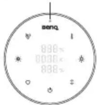
text_image
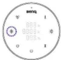
benq 880× 880× 880×How to Use
Turning On/Off the Lamp and Switching Light Modes Power On/Off
text_image
benq 800x 800x 800xTap the Power ⏻ button to turn on the lamp. To turn off the lamp, tap the Power ⏻ button again.
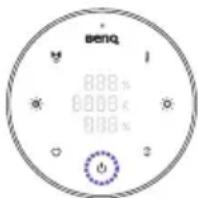
Light Mode Control

text_image
benq 000 x 8888 x 889 xTap the Light Mode Switch ↩ button to cycle through the following three light modes:
Front light on > Ambient light on > Both lights on
Auto Dimming Mode
text_image
benq 0000 0000 0000Tap the Auto Dimming Mode button to enter this mode. The indicator will light up when the mode is on. In the Auto Dimming Mode, the lamp automatically adjusts its brightness according to the surrounding lighting condition and sets the color temperature to 4000K.

- Avoid blocking the light sensor located on the lamp to ensure that the Auto Dimming Mode works correctly.
- The Auto Dimming Mode will automatically turn off when you adjust the brightness or the color temperature or switching light modes. Indicator will turn off when the mode is
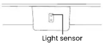
text_image
Light sensorAdjusting Brightness and Color Temperature
Brightness Control
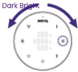
text_image
Dark Bright Beng 1 000+ 8889- 000+ 1-
With the lamp on, tap the Light Mode Switch ↑ button to select the light to be adjusted.
-
Tap the Brightness Adjustment button. The Brightness Adjustment indicator lights up. Rotate the adjustment ring to adjust the brightness: rotate the adjustment ring clockwise to increase the brightness, or rotate the adjustment ring counterclockwise to decrease the brightness. The current brightness value is shown on the display panel in real time. You can adjust the brightness in a range of brightness levels from 1 to 100.
Color Temperature Control
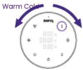
text_image
Warm Color benq 800x 800x 800xWith the lamp on, tap the Color Temperature Adjustment
button. The Color Temperature Adjustment indicator lights up. Rotate the adjustment ring to adjust the color temperature: rotate the adjustment ring clockwise to increase the color temperature, or rotate the adjustment ring counterclockwise to decrease the color temperature. The current color temperature value is shown on the display panel in real time. You can adjust the color temperature ranging from 2700K to 6500K in an increment of 25.
The color temperature settings of the front and ambient lights are identical and cannot be adjusted independently.
If the power supply is suddenly interrupted, the lamp will automatically return to its settings before the power outage when the power is restored.
- If the lamp was on before the power outage, it will automatically turn on when power is restored, and memorize the brightness and color temperature before the power outage.
- If the lamp was off before the power outage, it will remain off when power is restored.
Turning On/Off the Presence Detection Function
text_image
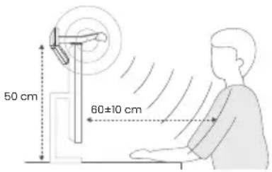
50 cm 60±10 cmThe Presence Detection function allows the light to turn on automatically when the user enters the detection area (as shown in the figure).
text_image
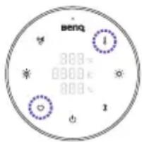
benq 800x 800x 800x 1- With the lamp on, tap and hold the Presence Detection button for 6 seconds. The Presence Detection indicator will blink.
- Rotate the adjustment ring to adjust the away detection time: rotate the adjustment ring clockwise to extend the detection time, or rotate the adjustment ring counterclockwise to shorten the detection time. The current detection time setting is shown on the display panel in real time. You can adjust the detection time setting within 3, 5, 10 and 15 minutes.
- If you finish the detection time setting, tap the Presence
Detection button again. The Presence Detection indicator and the Power indicator will flash. When they stop flashing, it means that the setting is memorized.
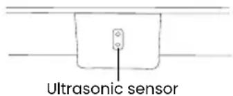
- The ultrasonic sensor will detect a conical area of 60 ± 10cm in front of the screen at a height of 50cm from the table.
- When the Presence Detection function is on, this function presets the light to turn off automatically after the user leaves the detection area for 5 minutes to save power.
- When the Presence Detection function is on, the Presence Detection (○) indicator light will flash for 30 seconds after the light is turned off manually, during which time the Presence Detection auto on/off function will be suspended. 30 seconds later the indicator light will turn off and the presence detection auto on/off function will resume normal operation, and the light will be turned on again automatically if you are still in the detection area at that time.
- Do not allow any object to block or cover the ultrasonic sensor on the lamp head to ensure that the Presence Detection function works properly.
- Do not insert or poke any objects into the ultrasonic sensor as this may affect the detection function.
- The Presence Detection function relies on the motion tracking technology. If you watch a movie in front of the screen for a long period of time in a fixed position, the sensor may determine that no one is present and turn off the lamp.
text_image
Ultrasonic sensorMy Favorite Mode
Setting Up My Favorite Mode

text_image
senq 888 x 888 x 888 x 1- Adjust the brightness, color temperature and light mode of the lamp.
- Tap and hold the My Favorite Mode ♥ button for about 3 seconds. The Brightness, the Color Temperature and the Auto Dimming Mode indicators will flash three times simultaneously to indicate that the settings are memorized successfully.
Using My Favorite Mode
Tap the My Favorite Mode button to enter this mode.
Pairing and Connecting Multiple ScreenBar Halo 2 Lamps
You can pair and connect a wireless controller with multiple ScreenBar Halo 2 lamps to operate at the same time. If the distance between the controller and these lamps is within 1 meter, the settings of these lamps will change simultaneously.
text_image
benq 300℃ 000℃ 800℃ 1-
Unplug the USB-C power cord.
-
Make sure that the power indicator is on (the wireless controller is activated) and the wireless controller is within 1 meter from the lamp.
-
While holding the My Favorite Mode ♥ button, tap and hold the Color Temperature Adjustment ↓ button for about 5 seconds. You will see the function indicators on the wireless controller start flashing simultaneously.
-
After the indicators start flashing, cover the light sensor (on the reverse side of the lamp head) of the lamp you wish to pair then plug in the
After the indicators start flashing, cover the light sensor (on the reverse side of the lamp head) of the lamp you wish to pair then plug in the USB-C power cord within 30 seconds. If the wireless controller and the lamps are successfully paired and connected, all the indicators will turn off and the wireless controller will go into sleep mode.
natural_image
Illustration of a hand holding a cylindrical object with a mechanical component attached (no text or symbols)Maintenance and Troubleshooting
- First turn off the lamp and unplug the lamp from the USB port. When cleaning the lamp, wipe off any smears or dusts using a soft, lint-free cloth lightly moistened with a mild detergent solvent. Do not use alcohol or any other chemical solvents like kerosene, naphtha and so on, as the lamp's casing may become damaged.
- Do not rinse the lamp or any of its components directly with water.
- If the lamp does not turn on or charge, make sure that the battery power of the wireless controller is sufficient and that the lamp is properly installed.
- If the problem persists, please contact the place of purchase for help.
| Light source Model Power (W) | Luminous flux (lm) | CCT (K) Dim | Efficiency Class | Weighted energy consumption (Ec) kWh/100 Oh | L_70B_50 lifetime (h) | QR code | |
| Light source-Front 7900 2700/4000/6500 Yes E 7 50000 |  | ||||||
| Light source-Back 3.5550 2700/4000/6500 Yes D | 4 50000 |  | |||||
- This product contains a front light source of energy efficiency class E.
- This product contains a back light source of energy efficiency class D.
• Light source (LED only) is replaceable by a professional.


Specifications
| Model CR23_C | |
| Lamp input 5V 15W Max. | —— |
| Dimensions (width x depth x height) | 50 x 14.3 x 10.9 cm |
| Power adapter model number and input | PS15J050K3000UC, 100-240V AC, 50/60Hz, Max. 0.5A or PS15K050K3000Z, 220-240V AC, 50/60Hz, Max. 0.5A |

text_image
50 cm (19.7 in) 4.74 cm (1.8 in) 150 cm (59.05 in) 7.4 cm (2.9 in) 3.95 cm (1.5 in) 3.34 cm (1.3 in) 14.38 cm (5.6 in) 0.38 cm (0.15 in) 10.91 cm (4.3 in)Verpackungsinhalt
natural_image
Line drawing of a mailbox with a flagpole and support structure (no text or symbols)
natural_image
Simple line drawing of a pole-mounted directional signpost (no text or symbols)
natural_image
Line drawing of a mechanical lever or pivot (no text or symbols)
natural_image
Line drawing of a mechanical lever or support structure (no text or symbols)natural_image
Pure mechanical diagram showing a lever mechanism with rotation arrow (no text or symbols)text_image
benq 888 0000 888 Itext_image
senq 0.000x 0.000x 0.000x I Inatural_image
Illustration of a hand holding a cylindrical object with a mechanical clamp (no text or symbols)flowchart
graph LR
    A["LED"] --> B["Bus Icon"]
    B --> C["LED"]
    C --> D["Square"]
Eigenschaften
natural_image
Simple line drawing of a pole-mounted mailbox with a curved handle and vertical support (no text or symbols)
natural_image
Simple line drawing of a pole-mounted device with a handle and bracket (no text or symbols)
natural_image
Simple line drawing of a mechanical clamp or bracket (no text or symbols)
natural_image
Line drawing of a mechanical lever or support structure (no text or symbols)natural_image
Pure mechanical diagram showing a lever mechanism with rotation arrow (no text or symbols)text_image
benq 888 x 888 x 888 xtext_image
senq 888 x 888 x 888 x 1natural_image
Illustration of a hand holding a cylindrical object with a mechanical clamp (no text or symbols)text_image
Monitor curvonatural_image
Line drawing of a mechanical lever or support structure (no text or symbols)natural_image
Diagram of a mechanical lever mechanism with directional arrows indicating rotation (no text or symbols)natural_image
Hand holding a cylindrical object with a mechanical clamp (no text or symbols visible)- 1x Controller wireless
- 1x Accessorio per webcam
- 1 x Guida rapida

natural_image
Simple line drawing of a pole-mounted mailbox or picket (no text or symbols)
natural_image
Simple line drawing of a pole-mounted directional lamp or stand (no text or symbols)
natural_image
Simple line drawing of a mechanical lever or fulcrum (no text or symbols)
natural_image
Simple line drawing of a mechanical lever or support structure (no text or symbols)natural_image
Diagram of a mechanical lever mechanism with directional arrows indicating motion (no text or symbols)text_image
benq 000x 8888x 888xtext_image
benq 800s 800s 800stext_image
senq 888 x 888 x 888 x 1natural_image
Illustration of a hand holding a cylindrical object with a mechanical clamp (no text or symbols)text_image
Diagram illustrating a mechanical assembly or installation procedure with labeled components and dimensional annotations.natural_image
Simple line drawing of a pole-mounted structure with two curved elements (no text or symbols)natural_image
Simple line drawing of a directional signpost with no text or symbolsGebogen monitor

natural_image
Pure mechanical diagram of a lever mechanism without any text or symbolsnatural_image
Simple line drawing of a mechanical lever or support structure (no text or symbols)natural_image
Diagram of a mechanical lever mechanism with directional arrows indicating motion (no text or symbols)flowchart
graph TD
    A["② Laparoscopic Device"] --> B["① Lateral Joint"]
    B --> C["③ Orthopedic Device"]
    C --> D["End of orthopedic device"]
text_image
Stroomindicator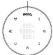
text_image
Benzq 800x 800x 800xtext_image
benq 888 x 888 x 888 xtext_image
BENQ 800s 800s 600stext_image
benq 888 888 888natural_image
Hand holding a cylindrical object with a mechanical clamp (no text or symbols visible)natural_image
Simple line drawing of a pole-mounted tower or support structure (no text or symbols)Bildskärm med rund
kant
natural_image
Simple line drawing of a mailbox with a flagpole (no text or symbols)Böjd bildskärm

natural_image
Simple line drawing of a mechanical clamp or bracket (no text or symbols)natural_image
Line drawing of a mechanical lever or support structure (no text or symbols)natural_image
Pure mechanical diagram showing a lever mechanism with a curved handle and a bracket, no text or symbols present.text_image
ON I ON benq 988x 988x 988xtext_image
seng 000c 8000c 000ctext_image
benq 8880 8880k 8880k 1natural_image
Hand holding a cylindrical object with a clamp or bracket, no visible text or symbolsnatural_image
Line drawing of a birdhouse with wings and legs (no text or symbols)
natural_image
Line drawing of a mailbox with a flagpole (no text or symbols)
natural_image
Simple line drawing of a mechanical clamp or bracket (no text or symbols)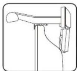
natural_image
Simple line drawing of a mechanical lever or support structure (no text or symbols)natural_image
Pure mechanical diagram showing a lever mechanism with no text or symbolsflowchart
graph TD
    A["Step 1: Hand placement on foot"] --> B["Step 2: Contact device"]
    B --> C["Step 3: Treatment on foot"]
    C --> D["Step 4: Hand placement on wrist"]
無線控制器充電
text_image
benq 888s 888c 888snatural_image
Simple line drawing of a pole-mounted mailbox with handle and spout (no text or symbols)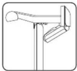
natural_image
Simple line drawing of a pole-mounted tower or stand with a curved handle and two vertical supports (no text or symbols)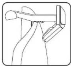
natural_image
Simple line drawing of a mechanical or electrical component with no text or symbols
natural_image
Line drawing of a mechanical lever or support structure (no text or symbols)natural_image
Pure mechanical diagram showing a lever mechanism with no text or symbolstext_image
BENQ 0.000x 0.000x 0.000xtext_image
Diagram illustrating a three-step robotic arm tool operation with labeled steps and hand positioning instructions.リモコンの充電方法
natural_image
Hand holding a long cylindrical object with a mechanical clamp or bracket (no text or symbols visible)故障・お手入れ
flowchart
graph TD
    A["I"] --> B["..."]
    B --> C["Box with '□' at bottom"]
    D["2"] --> E["←"]
    E --> F["Box with '□' at top"]
    G["3"] --> H["Box with '□' at bottom"]
natural_image
Diagram of a mechanical lever mechanism with directional arrows indicating rotation (no text or labels)natural_image
Hand holding a cylindrical object with a mechanical clamp, no visible text or symbolsDisposal of Waste Electrical and Electronic Equipment and/or Battery by users in private households in the European Union.
This symbol on the product or on the packaging indicates that this can not be disposed of as household waste. You must dispose of your waste equipment and/or battery by handling it over to the applicable take-back scheme for the recycling of electrical and electronic equipment and/or battery. For more information about recycling of this equipment and/or battery, please contact your city office, the shop where you purchased the equipment or your household waste disposal service. The recycling of materials will help to conserve natural resources and ensure that it is recycled in a manner that protects human health and environment.
Recycling Information: See https://www.beng.com/en-us/support/recycling/global-recycle.html for details.


https://www.beng.com/en-us/support/recycling/global-recycle.html.


DECLARATION OF CONFORMITY
The device complies with the requirements set out in the Council Directives on the Approximation of the Laws of the Member States relating Electromagnetic Compatibility (2004/108/EC) and Low Voltage Directive (2006/95/EC) and Radio and Telecommunications Terminal Equipment Directive (1999/5/EC), the Restriction of The Use of Certain Hazardous Substances in Electrical And Electronic Equipment Directive (2011/65/EU), Turkish EEE Directive; Turkish ErP (Decision 2010/643);the Commission Regulation (EC) No 1275/2008 implementing Directive 2005/32/EC of the European Parliament and of the Council with regard to eco-design requirements for standby and off mode electric power consumption of electrical and electronic household and office equipment, and the Commission Regulation (EC) No 1194/2012 implementing Directive 2009/125/EC of the European parliament and of the council establishing a framework for the setting of eco-design requirements for energy-related products.
Deutsch
DÉCLARATION DE CONFORMITÉ
Federal Communication Commission Interference Statement
This equipment has been tested and found to comply with the limits for a Class B digital device, pursuant to Part 15 of the FCC Rules. These limits are designed to provide reasonable protection against harmful interference in a residential installation. This equipment generates, uses and can radiate radio frequency energy and, if not installed and used in accordance with the instructions, may cause harmful interference to radio communications. However, there is no guarantee that interference will not occur in a particular installation. If this equipment does cause harmful interference to radio or television reception, which can be determined by turning the equipment off and on, the user is encouraged to try to correct the interference by one of the following measures:
- Reorient or relocate the receiving antenna.
- Increase the separation between the equipment and receiver.
- Connect the equipment into an outlet on a circuit different from that to which the receiver is connected.
- Consult the dealer or an experienced radio/TV technician for help.
FCC Caution: Any changes or modifications not expressly approved by the party responsible for compliance could void the user's authority to operate this equipment.
This device complies with Part 15 of the FCC Rules. Operation is subject to the following two conditions: (1) This device may not cause harmful interference, and (2) this device must accept any interference received, including interference that may cause undesired operation.
Industry Canada statement
This device contains licence-exempt transmitter(s)/receiver(s) that comply with Innovation, Science and Economic Development Canada's licence-exempt RSS(s). Operation is subject to the following two conditions: