TC2290DT - Audio Equipment TC ELECTRONIC - Free user manual and instructions
Find the device manual for free TC2290DT TC ELECTRONIC in PDF.
User questions about TC2290DT TC ELECTRONIC
0 question about this device. Answer the ones you know or ask your own.
Ask a new question about this device
Download the instructions for your Audio Equipment in PDF format for free! Find your manual TC2290DT - TC ELECTRONIC and take your electronic device back in hand. On this page are published all the documents necessary for the use of your device. TC2290DT by TC ELECTRONIC.
USER MANUAL TC2290DT TC ELECTRONIC
Legendary Dynamic Delay Plug-in with Optional Hardware Desktop Controller and Signature Presets

Table of Contents
EN
Important Safety Instructions 3
- Introduction 12
- Plug-in Installation.. 12
- Activate your TC2290 iLok License 13
- Connection and Setup 13
- Plug-in and Hardware Controls 16
- Operation 20
- Presets 23
- Software Updates 24
- Specifications 129
- Signal Flow Diagram 130
ES
Important Safety Instructions .......4
- Introduction 25
- Plug-in Installation.. 25
- Activate your TC2290 iLok License 26
- Connection and Setup 26
- Plug-in and Hardware Controls 29
- Operation 33
- Presets 36
- Software Updates 37
- Specifications 129
- Signal Flow Diagram 130
FR
Important Safety Instructions 5
- Introduction 38
- Plug-in Installation.. 38
- Activate your TC2290 iLok License 39
- Connection and Setup 39
- Plug-in and Hardware Controls 42
- Operation 46
- Presets 49
- Software Updates 50
- Specifications 129
- Signal Flow Diagram 130
DE
Important Safety Instructions .......6
- Introduction 51
- Plug-in Installation.. 51
- Activate your TC2290 iLok License 52
- Connection and Setup 52
- Plug-in and Hardware Controls 55
- Operation 59
- Presets.. 62
- Software Updates 63
- Specifications 129
- Signal Flow Diagram 130
PT
Important Safety Instructions .......7
- Introduction 64
- Plug-in Installation.. 64
- Activate your TC2290 iLok License 65
- Connection and Setup 65
- Plug-in and Hardware Controls 68
- Operation 72
- Presets.. 75
- Software Updates 76
- Specifications 129
- Signal Flow Diagram 130I
IT
Important Safety Instructions 8
- Introduction 77
- Plug-in Installation.. 77
- Activate your TC2290 iLok License 78
- Connection and Setup 78
- Plug-in and Hardware Controls 81
- Operation 85
- Presets 88
- Software Updates 89
- Specifications 129
- Signal Flow Diagram 130
NL
Important Safety Instructions .......9
- Introduction 90
- Plug-in Installation.. 90
- Activate your TC2290 iLok License 91
- Connection and Setup 91
- Plug-in and Hardware Controls 94
- Operation 98
- Presets 101
- Software Updates 102
- Specifications 129
- Signal Flow Diagram 130
SE
Important Safety Instructions ....10
- Introduction 103
- Plug-in Installation....103
- Activate your TC2290 iLok License 104
- Connection and Setup 104
- Plug-in and Hardware Controls 107
- Operation 111
- Presets 114
- Software Updates 115
- Specifications 129
- Signal Flow Diagram 130
PL
Important Safety Instructions ....11
1. Introduction 116
2. Plug-in Installation.. 116
3. Activate your TC2290 iLok License 117
4. Connection and Setup 117
5. Plug-in and Hardware Controls 120
6. Operation 124
7. Presets 127
8. Software Updates 128
9. Specifications 129
10. Signal Flow Diagram 130

Important Safety Instructions


Terminals marked with this symbol carry electrical current of sufficient magnitude to constitute risk of electric shock.
Use only high-quality professional speaker cables with 1/4'' TS or twist-locking plugs pre-installed. All other installation or modification should be performed only by qualified personnel.

This symbol, wherever it appears, alerts you to the presence of uninsulated dangerous voltage inside the
enclosure - voltage that may be sufficient to constitute a risk of shock.

This symbol, wherever it appears, alerts you to important operating and maintenance instructions in the
accompanying literature. Please read the manual.

Caution
To reduce the risk of electric shock, do not remove the top cover (or the rear section).
No user serviceable parts inside. Refer servicing to qualified personnel.

Caution
To reduce the risk of fire or electric shock, do not expose this appliance to rain and
moisture. The apparatus shall not be exposed to dripping or splashing liquids and no objects filled with liquids, such as vases, shall be placed on the apparatus.

Caution
These service instructions are for use by qualified service personnel only.
To reduce the risk of electric shock do not perform any servicing other than that contained in the operation instructions. Repairs have to be performed by qualified service personnel.
- Read these instructions.
- Keep these instructions.
- Heed all warnings.
- Follow all instructions.
- Do not use this apparatus near water.
- Clean only with dry cloth.
- Do not block any ventilation openings. Install in accordance with the manufacturer's instructions.
-
Do not install near any heat sources such as radiators, heat registers, stoves, or other apparatus (including amplifiers) that produce heat.
-
Do not defeat the safety purpose of the polarized or grounding-type plug. A polarized plug has two blades with one wider than the other. A grounding-type plug has two blades and a third grounding prong. The wide blade or the third prong are provided for your safety. If the provided plug does not fit into your outlet, consult an electrician for replacement of the obsolete outlet.
- Protect the power cord from being walked on or pinched particularly at plugs, convenience receptacles, and the point where they exit from the apparatus.
- Use only attachments/accessories specified by the manufacturer.

- Use only with the cart, stand, tripod, bracket, or table specified by the manufacturer, or sold with the apparatus. When a cart is used, use caution when moving the cart/apparatus combination to avoid
injury from tip-over.
- Unplug this apparatus during lightning storms or when unused for long periods of time.
- Refer all servicing to qualified service personnel. Servicing is required when the apparatus has been damaged in any way, such as power supply cord or plug is damaged, liquid has been spilled or objects have fallen into the apparatus, the apparatus has been exposed to rain or moisture, does not operate normally, or has been dropped.
- The apparatus shall be connected to a MAINS socket outlet with a protective earthing connection.
- Where the MAINS plug or an appliance coupler is used as the disconnect device, the disconnect device shall remain readily operable.

- Correct disposal of this product: This symbol indicates that this product must not be disposed of with household waste, according to the WEEE Directive (2012/19/EU) and your national law. This product
should be taken to a collection center licensed for the recycling of waste electrical and electronic equipment (EEE). The mishandling of this type of waste could have a possible negative impact on the environment and human health due to potentially hazardous substances that are generally associated with EEE. At the same time, your cooperation in the correct disposal of this product will contribute to the efficient use of natural resources. For more information about where you can take your waste equipment for recycling, please contact your local city office, or your household waste collection service.
18. Do not install in a confined space, such as a book case or similar unit.
19. Do not place naked flame sources, such as lighted candles, on the apparatus.
- Please keep the environmental aspects of battery disposal in mind. Batteries must be disposed-of at a battery collection point.
- This apparatus may be used in tropical and moderate climates up to 45^ .
LEGAL DISCLAIMER
Music Tribe accepts no liability for any loss which may be suffered by any person who relies either wholly or in part upon any description, photograph, or statement contained herein. Technical specifications, appearances and other information are subject to change without notice. All trademarks are the property of their respective owners. Midas, Klark Teknik, Lab Gruppen, Lake, Tannoy, Turbosound, TC Electronic, TC Helicon, Behringer, Bugera, Aston Microphones and Coolaudio are trademarks or registered trademarks of Music Tribe Global Brands Ltd. © Music Tribe Global Brands Ltd. 2021 All rights reserved.
LIMITED WARRANTY
For the applicable warranty terms and conditions and additional information regarding Music Tribe's Limited Warranty, please see complete details online at musictribe.com/warranty.
EN
ES
BESCHRANKTE GARANTIE
Read this manual to learn how to install and use your TC Electronic TC2290 delay unit. This manual is only available in PDF format from the TC Electronic website. To get the most from this manual, please read it from start to finish, or you may miss important information.
To download the most current version of this manual, visit the web page:
www.tcelectronic.com/Categories/c/Tcelectronic/Downloads
If you still have questions about your TC Electronic product after reading its manual, please get in touch with TC Support:
www.tcelectronic.com/brand/tcelectronic/support
2. Plug-in Installation
Visit www.tcelectronic.com/tc2290-dt/support/ to download the installer file. The plug-in requires either an iLok license (delivered when you purchase the NATIVE version) or the TC2290 DT Desktop Controller (when you purchase the DT Desktop Controller version) or an iLok Trial License. All parameters are available in the plug-in and most are available on the DT Desktop Controller.
Select the Mac or PC version and save the file to your hard drive. The latest firmware for the TC2290 DT Desktop Controller will be included in the software as well.
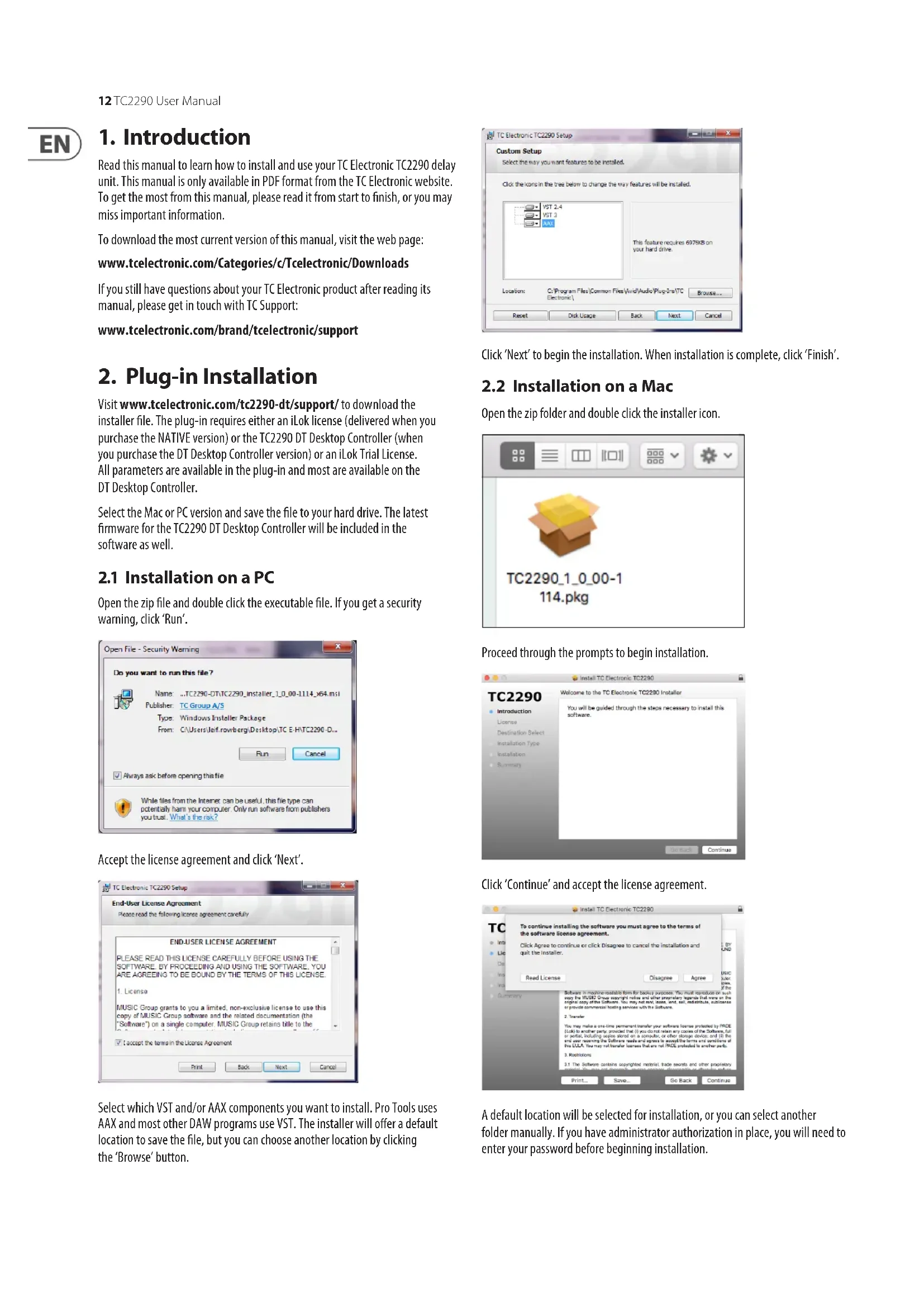
2.1 Installation on a PC
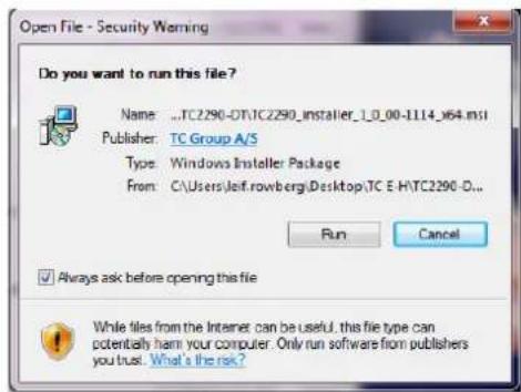
Open the zip file and double click the executable file. If you get a security warning, click 'Run'.
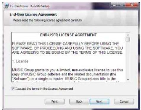
Accept the license agreement and click 'Next'.
Select which VST and/or AAX components you want to install. Pro Tools use AAX and most other DAW programs use VST. The installer will offer a default location to save the file, but you can choose another location by clicking the 'Browse' button.
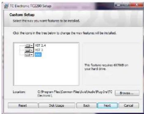
Click 'Next' to begin the installation. When installation is complete, click 'Finish'.
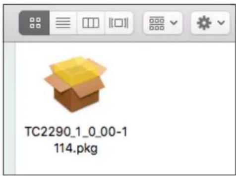
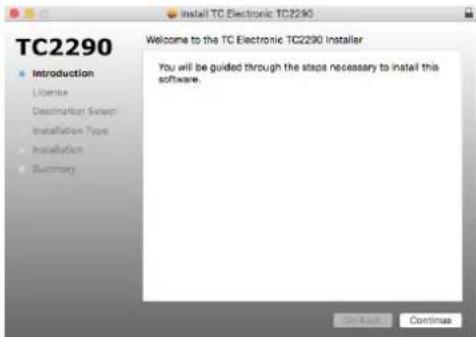
2.2 Installation on a Mac
Open the zip folder and double click the installer icon.
Proceed through the prompts to begin installation.
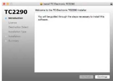
Click 'Continue' and accept the license agreement.
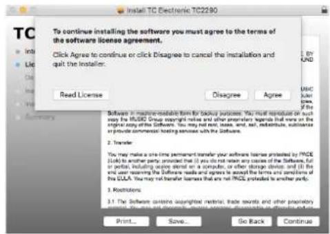
A default location will be selected for installation, or you can select another folder manually. If you have administrator authorization in place, you will need to enter your password before beginning installation.
3. Activate your TC2290 iLok License
3.1 Activation when you have purchased the NATIVE version
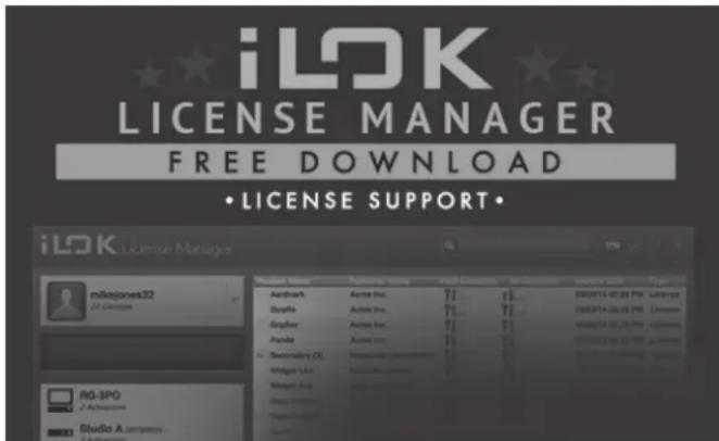
Step 1: Install iLok
The first step is to create an iLok user account at www.iLok.com and install the PACE iLok License Manager on your computer if it's your first time using iLok.
Step 2: Activation
In the received mail (when buying the NATIVE version) you will find your personal Activation Code. To activate your software, please use the Redeem an Activation Code feature in the PACE iLok License Manager.
3.2 Get a Free Demo License
Make use of this hassle-free offer to try out our plug-ins before you buy.
14-Day Trial Period
Fully Functional
- No Feature Limitations
- No Physical iLok Key Needed
Step 1: Install iLok
The first step is to create a free iLok user account at www.iLok.com and install the PACE iLok License Manager on your computer if it's your first time using iLok.
Step 2: Get your free license
Go to http://www.tcelectronic.com/brand/tcelectronic/free-trial-TC2290-native and enter your iLok User ID.
Step 3: Activation
Activate your software in the PACE iLok License Manager.
4. Connection and Setup
4.1 Connecting the TC2290-DT Desktop Controller (when you have purchased the DT Desktop Controller version)
Getting the Desktop Controller up and running couldn't get any easier. Plug the included USB cable into the unit's rear micro-USB port, and connect the other end to a free USB port on your computer. The Desktop Controller is bus powered so no other power cables are necessary, and no additional drivers need to be manually installed.
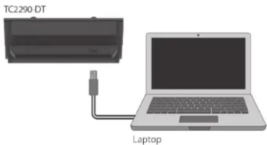
The Desktop Controller will light up upon successful connection. You can now apply the plug-in to a channel in your DAW to begin using the effect. This process may vary slightly depending on your software, but generally should require these steps:
- Select a channel or bus in your DAW to which you would like to add the effect. Access the mixer page where you should see a section dedicated to effect slots
- Open the menu where you can select from a list of effect types, which probably includes many stock plugins that are included with the DAW. There should be submenu to view general VST/AU/AAX options.
- The plug-in will likely be found in a dedicated TC Electronic folder. Select the TC2290 and it will now be added to the signal chain.
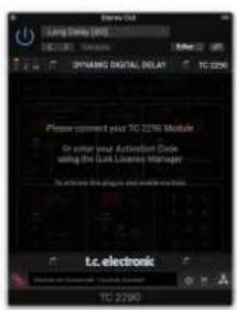
Double click on the effect slot that contains the TC2290 to view the plug-in UI. There should be a green link icon at the bottom, and text that indicates successful connection between the plug-in and the Desktop Controller.
Note: The iLok License Manager needs to be installed on your computer also if you have purchased the DT Desktop Controller version. In this case you don't need to create an iLok account or activate any license.
4.2 Operating the TC2290
After you have installed the plug-in, and either activated the iLok license or connected the TC2290-DT Desktop Controller via USB, you can begin inserting the plug-in to your tracks.
Adjustments to the effect are done in two ways. Either by using the plug-in user interface or via the physical Desktop Controller.

4.3 Insert vs Aux Effect
The TC2290 can be inserted directly into an effect slot on a single channel, as described above, which passes the entire signal through the effect. In this case, note that the direct input signal becomes mono before it is panned, either statically or modulated. This occurs when the PAN/DYN section DIRECT button is engaged.
However, the TC2290 can also be added to an auxiliary bus, and one or more channels can send a portion of their signal to this bus to be processed by the effect. The output of the effect is then mixed back in with the rest of the tracks. This differs from an insert effect in that the TC2290 isn't affecting the track's entire signal, so the direct signal cannot be modulated using the MOD buttons in the PAN/DYN section. In this setup, the Mix parameter should always be set to 100% .
4.4 Mono/Stereo Operation
The TC2290 can be used both as a mono instance on mono tracks and a stereo instance on stereo tracks. Depending on the specific DAW, a mono in/stereo out may also be available.
In the case of a mono out instance, the output signal is made by outputting the left plug-in channel only. In this case, panning should not be used.
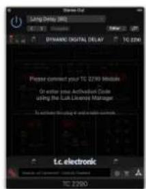
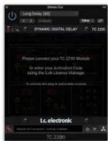
4.5 Travel Period and Module Connection (when you have purchased the DT version):
You can try out the plug-in before purchasing or receiving your purchased Desktop Controller by requesting a Free iLok Trial License, which will enable full functionality for 14 days.
When you receive and connect your purchased Desktop Controller you will no longer need an iLok License to have full functionality in the plug-in or via the Desktop Controller.
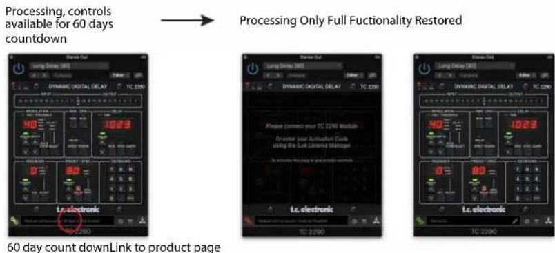
60-day Travel Period
If the Desktop Controller is disconnected, full plug-in functionality will be available for 60 days, after which the plug-in requests re-connection to the hardware unit. Once the hardware unit is re-connected, all controls become available.
Download and install the plug-in and connect the module Full Fuctionality
Processing, controls available for 60 days countdown
with store finder
Disconnect Module 60 days... Reconnect Module

Processing Only Full Fuctionality Restored
60 day count downLink to product page
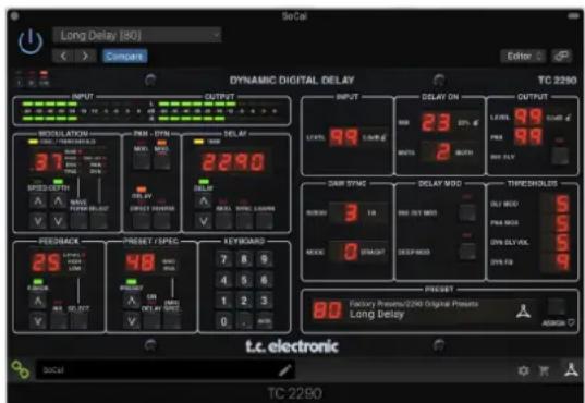
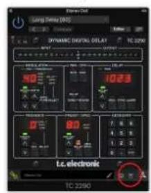
4.6 Primary and Secondary Controls
After you have installed the plug-in and activated the iLok license or connected the TC2290 via USB, you can begin adding the effect to your tracks.
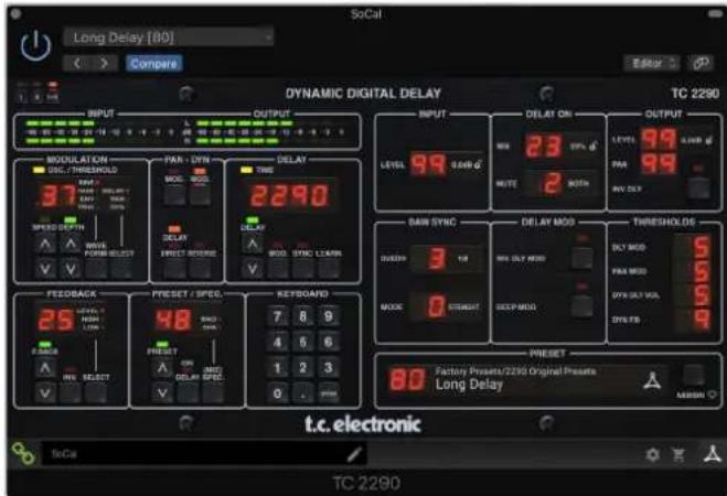
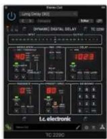
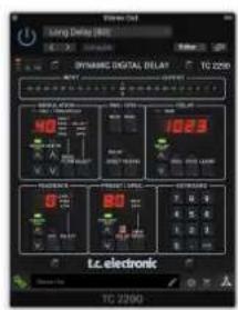
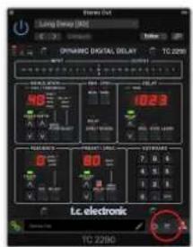
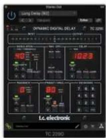
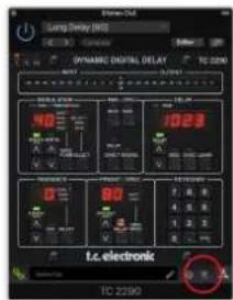
The plug-in is divided into two sections, which are both visible when the "I+II" button at the top left is selected. The left section is identical to the hardware unit and could be considered Primary parameters. These include common items such as delay time and feedback.
The right side contains the Secondary parameters. The secondary parameters are the ones that were known as "SPEC KEYS" (Special Keys) on the original 2290. These parameters can be called from the hardware unit using the SPEC KEYS.
To reduce plug-in size on your screen you can select "I" or "II" in the top left of the plug-in. "I" will show the left section of the plug-in only and "II" will show the right section. Setting "II" can be a complementary setting when using the hardware unit.
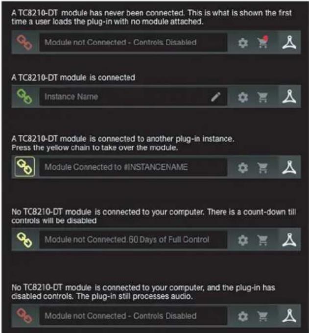
4.7 Connection Status to the Hardware Unit
The TC Icon family all use the same method to show the connection status between the plug-in and the hardware unit.
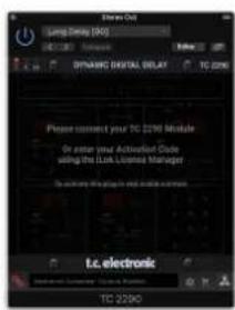
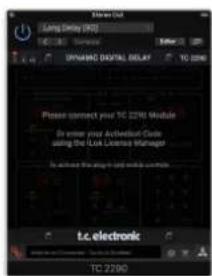
Connection status is indicated on the lower left side of the plug-in window. Successful connection is indicated with a green chain icon. When using the NATIVE version only, this chain icon will remain grey.
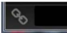
There are 3 conditions that will result in a "Not connected" status. If another instance of the plug-in already exists on another track, the chain icon will appear yellow with a yellow frame, and the text box will notify you where the plug-in is currently active. Click the chain icon to connect the hardware unit to the new plug-in location. The yellow icon may also appear while the connection is being made between the TC2290 unit and the plug-in, accompanied by "Connecting..." text.

If the hardware unit is disconnected from the computer, but the countdown has not yet expired, a yellow chain icon without the yellow frame will appear. See "Travel Period and Module Connection" section for details.

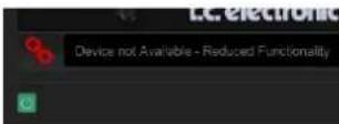
All other "Not connected" states are indicated by a red chain icon. This could happen if the USB cable is disconnected, the TC2290 connection is disrupted, or other issues.
To summarize the connection status possibilities:
Most DAWs offer the ability to move or drag plug-ins from one track/bus to another, and TC2290 supports this as well.
Most DAWs also feature an on/off switch for plug-ins, accessible inside the plug-in window and/or the track itself. Muting the plug-in will make the effect inaudible, but will not shut down the connection to use the hardware unit.

EN
5. Plug-in and Hardware Controls
Control of the TC2290 is done in the plug-in or optionally done using the hardware unit (when you have purchased the DT version). All primary parameters of the 2290 are also accessible through the DT Desktop Controller. These include parameters that control major parts of the effect, such as delay time, modulation, preset changes, mix (via 'Special' control) and much more. Secondary parameters that are needed less often are handled in the plug-in window in its right section. These are parameters like modulation thresholds, subdivision, preset save and more.
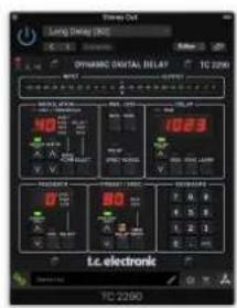
5.1 Primary Plug-in and Hardware Controls
Meters
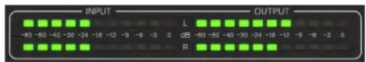
The meter section gives feedback about the incoming and outgoing audio signals. The input level displays the audio as it enters the plug-in, and is not affected by adjustments to the input level control or any other parameter. The output meter is affected by the results of the effect as well as the output level control parameter.
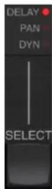
MODULATION
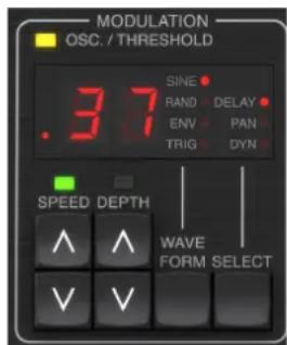
This section controls parameters of the modulation effects. Note that the modulation is actually engaged with the MOD buttons located in the PAN, DYN and DELAY sections.
Pressing the SELECT button scrolls through the parameter sets for the DELAY, PAN and DYNAMICS, essentially selecting the focus of the other buttons in this section. The types of modulation effects include:
Delay time modulations - chorus, flanger, pitch, auto-doubling.
- Pan position modulations - auto-panning of the direct signal, delay signal, or both.
- Dynamic modulation - tremolo, delay compressor/expander, ducking and gating.
Each of these parameter sets consists of the following values:
WAVEFORM - determines the modulation waveform, between sine wave (SINE), random wave (RAND), input signal envelope controlled (ENV), or input level triggered (TRIG). The modulation target determines the function of ENV and TRIG.
SPEED - Pressing UP or DOWN once will bring focus to the SPEED parameter, and additional presses will move the value by one step. The SPEED parameter is shown in Hz (cycles per second). Depending on the modulation target, when the ENV or TRIG Waveform is selected, the parameter controls the speed from no effect to maximum effect. A setting of "1" means a ramp time of 1 second, whereas a setting of "5" means a ramp time of 12 of a second.
DEPTH - Pressing UP or DOWN once will bring focus to the DEPTH parameter, and additional presses will move the value by one step. The DEPTH value is displayed in percentage of maximum modulation.
Pressing the SPEED or DEPTH arrow keys will first bring focus to that parameter, which also allows a specific value to be entered on the KEYBOARD, followed by the ENTER key. When either parameter is active, a green LED will flash above and the display will show the current value.
The yellow OSC/THRESHOLD LED in the upper left corner of this section shows modulation speed when using periodic modulations (SINE, RANDOM) and indicates when the input level passes the threshold for ENV or TRIG effects.
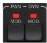
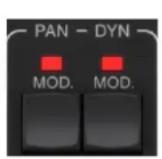
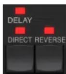
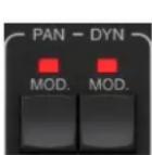
PAN/DYN
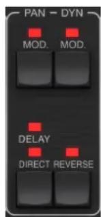
Press either of the MOD buttons beneath the PAN and DYN labels to engage those functions respectively. The red LEDs above each button indicate the on/off status. The parameters for each effect are adjusted in the MODULATION section.
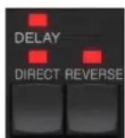
The DELAY/DIRECT button determines if the PAN effect is applied to the delay signal only, the direct signal only, both or neither. This also applies to the static pan set in the plug-in, so if neither DELAY nor DIRECT is lit, there is no panning at all.
When neither DELAY nor DIRECT is lit, the delay signal is phase inverted in the right channel. This is nice for creating wide chorus/flanger effects, but may not be desired for delay effects. To circumvent this, set PAN in the plug-in to 50, disengage PAN MOD, and enable PAN DELAY (not DIRECT). This will give the same result minus the phase inverse of right delay signal.
Note that whenever DIRECT is lit, the direct signal will first be summed to mono and then panned. When DIRECT is not lit, the direct signal will be stereo (if the plug-in is a stereo instance).
The REVERSE button causes the selected Dynamic effect to function in an opposite way. With the Waveform set to SINE or RAND, a tremolo effect is achieved which produces a modulated increase/decrease in volume. When the REVERSE button is activated, this creates a modulation that enhances delay volume when direct volume is suppressed and vice versa.
With the Waveform set to ENV or TRIG, the REVERSE button changes the usual Compression/Ducking effects into Expansion/Gating effects.
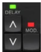
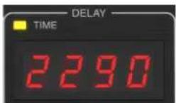
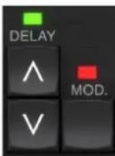
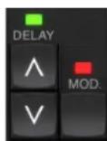
DELAY
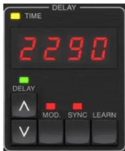
The main function of this section is to control the delay time. The yellow LED above the display will flash in rhythm with the current tempo, and the exact time in ms will be displayed. There are several ways to adjust the delay time:
Using the UP/DOWN arrows
- Using the KEYBOARD (after pressing UP/DOWN arrows once)
- Pressing the LEARN button in rhythm with your desired tempo
- Pressing the SYNC button to synchronize the tempo with the DAW tempo
A single press of the UP or DOWN arrow keys will bring focus to the delay tempo setting. Doing so causes the green LED to flash, and the tempo can now be adjusted. Pressing UP or DOWN will change the tempo by single digit increments, or holding the button will allow the parameter to scroll quickly.
However, once the green LED is flashing, the KEYBOARD can also be used to manually enter a delay time, followed by the ENTER key. If you use the KEYBOARD to enter the delay time, please note that you can enter values with decimals, including values below one millisecond by pressing the dot. For example, a delay time of 8.5 ms can be dialed by pressing [8] [dot] [5] [ENTER].
If you don't know the exact tempo measurement for your desired tempo, you can get fairly close by tapping the LEARN button in rhythm. The time between the first and second press will used as the new tempo.
The TC2290 can also follow the tempo currently set in your DAW. Press the SYNC button to enable this. Once enabled, the UP and DOWN buttons will change the subdivision of the beat.
To enable modulation of the delay signal, press the MOD button. See the MODULATION section in this chapter as well as Chapter 5 for details.
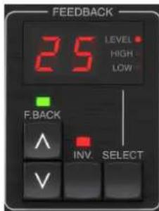
FEEDBACK
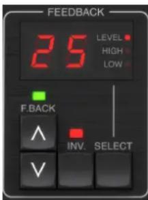
This section primarily controls the number of delay repeats, but it also affects other functions.
Pressing the SELECT button scrolls through the 3 adjustable parameters in this section - feedback LEVEL, HIGH cut, and LOW cut filters. The display will indicate the current selection as well as the value for that parameter.
Pressing the UP or DOWN arrow buttons will activate the adjustment for the selected parameter, causing the green LED to flash. Further presses will change the value by one step, or holding the button will scroll rapidly. With the green LED flashing, an exact value can be entered on the KEYBOARD, followed by the ENTER button. The possible values for the 3 parameters are as follows:
- Feedback - 0-99%
- High cut - 2, 4, 8, 33 kHz (33 kHz = off)
Low cut-0, 0.1, 0.2, 0.4 kHz (0 = off, 0.1 = 100 Hz, etc.)
Pressing the INV button inverts the feedback signal, which may not be noticeable with echo effects, but is more pronounced when applied to modulation such as flanger.
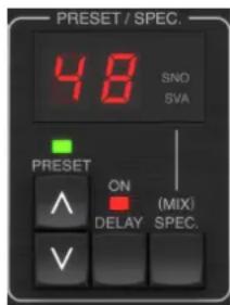
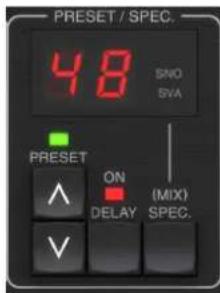
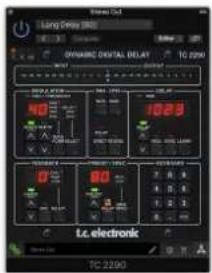
PRESET/SPEC

Pressing the DELAY ON button toggles the delay effect on and off, indicated by the red LED. However, after turning this switch off, the direct signal is still heard along with any panning effects. Note that the static pan position (set by PAN in plug-in) is only used when DELAY ON is not lit when Spec key 26 (MUTE) is set to 0 (IN). Otherwise (Spec 26 non-zero), the direct pan position is center.
Pressing the UP or DOWN arrow once will engage the preset selection, allowing presets to be scrolled one-by-one, or a specific preset can be entered on the KEYBOARD, followed by the ENTER button. See Chapter 6 for details.
The SPEC (Special) button allows control of some parameters that are otherwise only accessible in the plug-in window. Pressing the SPEC button accesses the Special Number (SNO) and the Special Value (SVA). The Special Number can only be entered on the KEYBOARD, followed by the ENTER button, whereas the Special Value can be entered with the KEYBOARD or preset arrow keys. The following chart shows the available parameters that can be controlled:
| Special Number Parameter Possible Values | ||
| 1 Input Level | 0-99 (off - 0 dB) | |
| 2 Delay Mix | (default) 0-99% | |
| 3 Output Level | 0-99 (off - 0 dB) | |
| 4 Pan 0-99 | ||
| 5 Invert Delay | 0 (off), 1 (on) | |
| 6 DAW Sync | Subdivision 0-6 (64th note - whole note) | |
| 7 DAW Sync | Mode 0 (straight), 1 (dotted), 2 (triplet) | |
| 8 Delay Deep | Mod 0 (off), 1 (on) | |
| 9 Invert Delay | Mod 0 (off), 1 (on) | |
| 10 | Delay Mod Threshold | 1-9 |
| 11 | Pan Mod Threshold 1-9 | |
| 12 | Dynamic Delay Volume | 1-9 |
| 13 | Dynamic Feedback | 1-9 |
| 26 | Mute Method | 0 (In), 1 (Out), 2 (Both) |

Knowing that DELAY MIX will likely be the most common plug-in parameter that users will need to access regularly, this has been programmed as the default Special Number. As soon as the SPEC button is pressed, Special #2 (DELAY MIX) will appear as the SNO entry, and the SPEC button can be pressed again to toggle focus to the DELAY MIX value (SVA). Use the arrow keys or KEYBOARD to enter the desired value. Press SPEC again to return to the normal preset select state.

To access a Special number other than DELAY MIX, press the SPEC button until SNO is highlighted with a red LED. Dial the desired Special Number on the KEYBOARD and press ENTER, which will automatically toggle the SPEC focus to Special Value (SVA). Dial the value using the UP/DOWN arrows or the KEYBOARD.
KEYBOARD
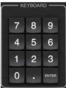
The KEYBOARD section is used to enter specific values or presets instead of scrolling with arrow buttons. Generally, when entering a specific value, the green LED associated with that parameter section must be flashing in order for the KEYBOARD to take effect. After a value has been chosen, press the ENTER button to confirm.
5.2 Plug-in Controls - Secondary Parameters
INPUT
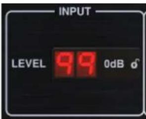
Click and drag up or down to adjust the input level from 0 to 99. Alternatively, double click on the numeral to enter a value manually. A setting of 0 is - and a setting of 1 is -96 dB. The level increases in 3 dB increments at lower settings, and by 0.5 dB increments above -40 dB.
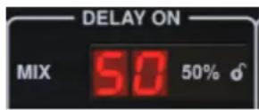
DELAY ON
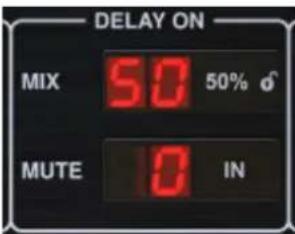
Click and drag the MIX parameter to adjust the balance between the direct and delay signals.
Click the right side of the MUTE mode parameter to select whether muting affects the input or output signals, or both. Muting the input will allow the echo tail to fade naturally after the effect is bypassed.
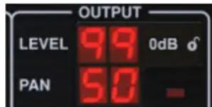
OUTPUT
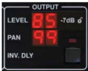
Click and drag up or down to adjust the output level from 0 to 99. A setting of 0 is - , and a setting of 1 is -96 dB. The level increases in 3 dB increments at lower settings, and by 0.5 dB increments above -40 dB.
Adjust the pan position of the signal by clicking and dragging the PAN parameter. Panning is only applied to signals chosen with the DELAY/DIRECT button in the PAN section of the hardware unit. With a setting of 50, both the direct and delay signals are centered. A setting of 0 places the direct signal hard right and delay hard left. A setting of 99 places the direct signal hard left and the delay signal hard right.
When the INV DLY button is activated, the output of the delay signal is phase inverted.
Lock Symbol
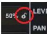
Some of the parameters can by locked from being recalled when a new preset is selected. Locked parameters will always keep their values no matter which preset you recall.
A great example of use is using it with the MIX parameter.
The default presets provided in the plug-in are typically created with the intent that the effect will be inserted on the track (as an insert effects). A MIX value has been chosen that will work for that preset.
However, if you'd like to use the TC2290 as a send/parallel effect, the MIX parameter should typically be set to 100% . After setting the MIX to 100% , use the lock function to make sure it stays at 100% even if you load another preset
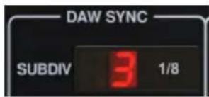
DAWSYNC
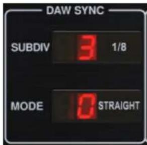
When the DAW SYNC selection is active (by pressing the SYNC button on the unit), some parameters can be adjusted to control the relationship between the delay and the DAW tempo.
The delay subdivision (SUBDIV) can be set anywhere from 1/64th note to a whole note. Note that this can also be adjusted using the arrow buttons in the DELAY section on the unit.
The subdivision can also be heard in straight time, dotted, or triplet feel by adjusting the MODE setting.
DELAY MOD
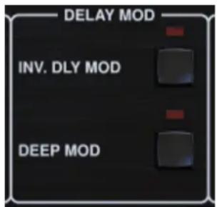
When engaged, the INV DLY MOD button inverts the flanger sweep start and the envelope pitchshift direction. This only applies to Delay Mod Waveforms ENV and TRIG.
Engage the DEEP MOD by pressing the button. DEEP MOD disables the automatic modulation depth mapping known as "Golden Ratio". This makes it possible to do much deeper modulation with wild pitch shifts, but it is somewhat uncontrollable.
THRESHOLDS
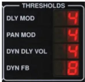
All 4 of these items offer 9 threshold settings for their respective parameter. Range for each parameter is 1-9.
DLY MOD - Delay ENV and TRIG waveforms.
PAN MOD - Pan ENV and TRIG waveforms.
DYN DLY VOL - Determines the threshold for the volume modulation of the delay (and direct for ENV REVERSE) signal when DYN modulation is ENV or TRIG.
DYN FB - Determines the threshold for the modulation of the feedback level when DYN modulation waveform TRIG is selected (not ENV).
These set the thresholds associated with the Envelope (ENV) and Trigger (TRIG) modulation forms. The higher the value, the higher input signal is necessary to get the same modulation effect. Delay, Pan and Dynamic thresholds are adjustable in 3 dB steps. The OSC./THRESHOLD LED indicates the current operating state, and can therefore be used as help for setting the threshold.
PRESET
Use the PRESET section to recall and save presets as well as assigning them as favorites. See Chapter 6 for details.
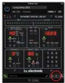
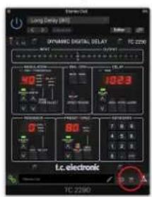
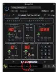
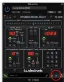
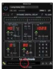
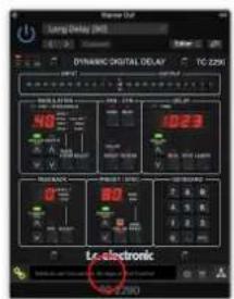
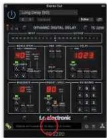
Bottom section
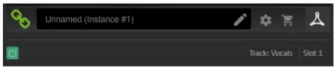
The bottom portion of the plug-in window displays connection status as well as plug-in instance name, and has several options available.
The green chain icon indicates successful connection between the hardware unit and the plug-in. Connection issues will be indicated by yellow or red icons; see Chapter 3 for details.
The current name of the plug-in instance appears in the middle field. If the DAW is able to provide the name of the track where the plug-in instance is inserted, the plug-in instance will be named after the track name. The instance can be renamed by clicking the pencil icon.
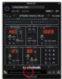
If you install the plug-in without connecting the hardware unit to your computer, a red dot will appear on the shopping cart icon. This will link you to more information about buying the TC2290 unit. Once the plug-in detects a connected hardware unit, the red dot will disappear.
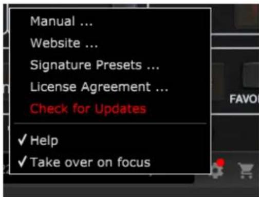
The Settings icon accesses a menu with several links and options. This user manual is available, along with links to the TC Electronic website, relevant news, additional signature artist presets, and the user license agreement. If a red dot appears over the Settings icon, a new version of the plug-in or firmware may be available. Click "Check for Updates" to download and install the new file. See Chapter 7 for details.
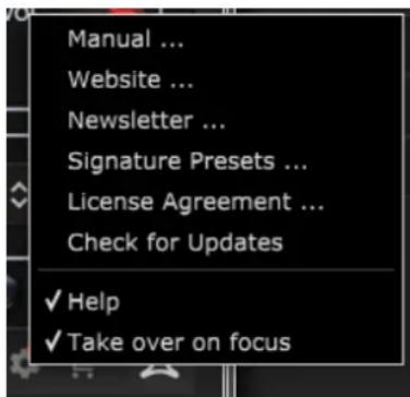
With the "Help" option selected, hovering the mouse over a certain item in the plug-in window will give a brief description of the parameter's function and the Special key number (if applicable).
With the "Take over on focus" option selected, the currently viewed plug-in instance will take over control of the physical hardware unit as soon as it is brought into focus.
Also, when a new instance of the plug-in is inserted on a track or bus, that instance will take over immediately.

6. Operation
This chapter will discuss the details of creating certain effects and how to adjust each parameter. After you have inserted the plug-in in a channel or bus, and optionally connected your DT Desktop Controller, you are now ready to start experimenting with the capabilities of the TC2290.
On the hardware unit, in the PRESET/SPEC section, make sure the DELAY ON button is active (LED lit). Most of the significant effect parameters are accessed on the hardware unit, so we'll focus attention there.
6.1 Delay Parameters
The TC2290 is, first and foremost, a delay unit, so we can start with the 3 main parameters:
Delay time - This controls the rate of the echoes.
Feedback-This controls how many echoes are heard.
- Mix - This adjusts the volume balance between the delay echoes and the direct signal.
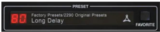
Delay Time
If you select a default preset that uses delay (#80 for example), you'll see that the yellow TIME LED above the DELAY display will flash in rhythm with the current tempo, and the exact time in ms will be displayed.
There are several ways to adjust the delay time:
Using the UP/DOWN arrows
Using the KEYBOARD (after pressing UP/DOWN arrows once)
- Pressing the LEARN button in rhythm with your desired tempo
- Pressing the SYNC button to synchronize the tempo with the current DAW tempo
A single press of the UP or DOWN arrow keys will bring focus to the delay tempo setting. Doing so causes the green LED to flash, indicating that the tempo can now be adjusted manually.

Pressing UP or DOWN will change the tempo by single digit increments, or holding the button will allow the parameter to scroll quickly. However, once the green LED is flashing, the KEYBOARD number pad can also be used to manually enter a delay time, followed by the ENTER key.

If you don't know the exact tempo measurement for your desired tempo, you can get fairly close by tapping the LEARN button in rhythm. The time between the first and second press will used as the new tempo. You can see on the display that the first press causes the numbers to start from 0 and ascend very quickly (these are milliseconds after all). If you do this several times, you may notice that you get a slightly different result each time, so the tempo may still need to be tweaked manually using the arrow buttons.
The TC2290 can also follow the tempo currently set in your DAW. Press the SYNC button to enable this. Let's say your DAW tempo is set to 120 BPM, which tends to be the default setting in a new project/session.
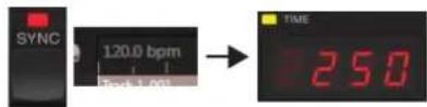
Press the SYNC button, and the TC2290 will convert the tempo into ms, which is 250.
Once SYNC is enabled, the UP and DOWN buttons will change the subdivision of the beat. The subdivision is currently set to eighth notes in the DAW SYNC section of the plug-in window, which gives us 250 ms at 120 BPM.
This can be changed to quarter notes by pressing the UP button in the DELAY section of the hardware unit, or making the change in the DAW SYNC section of the plug-in window. Making a change to one will cause the other to be altered as well. Change the subdivision to quarter notes, and you now have a delay time of 500 ms.

Even with DAW SYNC enabled, the LEARN button can still be used to set the tempo. When this is done, the TC2290 will grid to the nearest subdivision and mode (Straight, Dotted, Tripled) within the DAW-synced tempo, and set the delay time accordingly.
FEEDBACK
Feedback controls the number of echoes that are created by the effect.
Press the SELECT button until the LED next to LEVEL is lit. This ensures that we are adjusting the feedback parameter and not the high or low cut filters.
Pressing the UP or DOWN arrow buttons causes the green LED in this section to flash. We can now adjust the feedback parameter, either by pressing or holding the UP/DOWN buttons, or by entering a value with the KEYBOARD followed by the ENTER key.
MIX
The last parameter to adjust a basic delay setting is the MIX between the echoes and the direct signal. To access this parameter, press SPEC twice and use the UP/DOWN arrows to set the MIX.
Alternatively, the MIX setting can be adjusted using the plug-in UI.
If using the plug-in as an insert on a channel, you will likely want a setting below 50% to avoid a muddy-sounding result. However, if using the plug-in as a send/aux effect, set the MIX to 100% .
6.2 Modulation Effects
The TC2290 has 3 kinds of modulation effects available:
- Delay Time modulations - chorus, flanger, pitch modulation, auto-doubling effects.
Dynamic modulations - tremolo, compress/expand, ducking/gating effects.
Pan position modulations - auto-panning effects.
Each of these effects has its own MOD on/off button.
The parameters for each of these modulations are controlled in the MODULATION section on the hardware unit. By using the SELECT button within this section, you can scroll through the 3 types of modulation.
After the modulation type has been selected, the 3 parameters in this section can be adjusted, which are:
WAVEFORM - determines the modulation waveform, between sine wave (SINE), random wave (RAND), input signal envelope controlled (ENV), or input level triggered (TRIG). The modulation target determines the function of ENV and TRIG.
SPEED - Pressing UP or DOWN once will bring focus to the SPEED parameter, and additional presses will move the value by one step. The SPEED parameter is shown in Hz (cycles per second).
Depending on the modulation target, when the ENV or TRIG Waveform is selected, the SPEED parameter controls the rate of change from no effect to maximum effect. A setting of "1" means a ramp time of 1 second, whereas a setting of "5" means a ramp time of 12 of a second.
DEPTH - Pressing UP or DOWN once will bring focus to the DEPTH parameter, and additional presses will move the value by one step. The DEPTH value is displayed in percentage of maximum modulation.
Pressing the SPEED or DEPTH arrow keys will first bring focus to that parameter, causing a green LED to flash above and the display to show the current value. This means the arrow buttons can change the value by single steps, and also allows a specific value to be entered on the KEYBOARD, followed by the ENTER key.
Note- the feedback parameter of the delay may also have an effect on modulation effects.
Each of these parameters affects the sound differently depending on the specific effect. Let's review each type of modulation and how it can be adjusted.
6.2.1 Dynamic Effects
In the MODULATION section, use the SELECT button to highlight the Dynamics (DYN) parameters. Ensure that the MOD button is engaged in the center PAN/DYN section.
Ducking Delay
A ducking delay uses the input signal to attenuate the delay signal, causing the echoes to stay "out of the way" while you're playing, but still allow the echo tails to be audible during gaps in your playing.
Press the WAVEFORM button until TRIG is selected. This selects the ducking effect.
Press the DEPTH UP or DOWN button to shift focus to this parameter. The green LED will flash above and the current value is displayed. This parameter controls how much the delay signal is attenuated. Lower the value for small amounts of attenuation, or raise it to make the effect almost inaudible while you're playing.
Press the SPEED UP or DOWN button to shift focus to this parameter. This controls the rate at which the attenuation is released. Lower values allow a longer period of time to pass after you stop playing before the echoes increase to their normal volume. Higher values let the echoes come in quickly.
Gated Delay
By pressing the REVERSE button in the PAN/DYN section, the ducking effect becomes a gated delay. Set this way, the effect will only be heard while you are playing, and will be attenuated when you stop.
Tremolo Effect
Press the WAVEFORM button until SINE or RAND are selected. This creates a tremolo effect where the volume of both the direct and delay signals are attenuated and then return to full volume, up and down at a constant rate (SINE only). Use the SPEED parameter to adjust the specific rate, and the DEPTH to adjust the amount of attenuation.
EN
By engaging the REVERSE button, the direct signal and delay signal are attenuated opposite one another, with the direct reaching full volume while the delay is at maximum attenuation, and vice versa.
Compressor/Expander Effect
Press the WAVEFORM button until ENV is selected. This produces a compressed delay sound similar to the ducking effect, but less pronounced and leaves the feedback unaffected.
Engaging the REVERSE button produces an expander effect that affects the direct and delay signals. Initial transients are attenuated, creating an 'attack-kill' effect. The SPEED parameter controls how quickly the volume swells to normal level, and the DEPTH parameter controls the amount of initial attenuation.
6.2.2 Chorus/Flanger/Doubling Effects
In the MODULATION section, use the SELECT button to highlight the DELAY parameters. Ensure that the MOD button is engaged in the DELAY section.
Several types of modulation can be achieved by setting very short delay times, which are not heard as an echo, but rather as an extra, synchronized voice. Some common delay and feedback levels are outlined here:
| Delay Time Effect | MOD button | Feedback Setting | Mix | |
| 0-10 Flange | ON Very High 50 | |||
| 5-50 Chorus | ON Slight or none | 50 | ||
| 20-80 | Double Track | ON | Slight or none | 50 |
| 100-up | Delayed Chorus | ON | Set for repeats | 50 |
Chorus
Chorus effect is achieved by mixing the direct signal with a modulated delay signal. The result is a multi-voice character that sounds like more than one instrument playing in unison, with small variations in pitch and time.
In the DELAY section, set the time very low - around 20-25 ms. In the FEEDBACK section, reduce the level all the way to 0.
Press the WAVEFORM button to select SINE, which is very common for Chorus effects. Other waveforms will be discussed later in this chapter.
In the MODULATION section, ensure that DELAY is selected, and adjust the DEPTH parameter to control the intensity of the effect. Higher values create a deeper detune. Adjust the SPEED parameter to control the rate of the modulations.
Note that setting the MIX control to 99 produces a pure vibrato effect, where the pitch is modulated up and down without the direct signal to create the 2 voices.
Flanger
Flanger effects produce sweeping wave-like modulations that create a thick, often psychedelic sound. This will operate similarly to the chorus effect, with a few adjustments.
In the FEEDBACK section, raise the feedback level parameter to 50. The higher the feedback setting, the more resonant the flanger effect will be. Settings below 90 are recommended.
For classic jet flanger effects, set the DELAY time around 2 ms.
In the MODULATION section, try setting the SPEED parameter very low to make the sweeps slower. Increasing the DEPTH parameter produces wider sweeps.
Other Waveforms
Though the SINE option will give you recognizable chorus and flanger sounds, there are other effects achievable with different waveforms. The RAND setting will yield a random sweep instead of the continuous form of the SINE.
The ENV setting produces a ramp that starts and stops with the input level. Higher SPEED settings and moderate DEPTH settings might be necessary.
Selecting TRIG creates a sine sweep that stops whenever the input signal stops. This allows the sweep to be synchronized along with the music.
Auto Doubling
This effect is a specific type of chorus that gives the impression of 2 identical players/singers performing the same part in unison. Try low DELAY times around 20-80 ms, low FEEDBACK setting, slight pitch shift, slight volume modulation, and changes in panning position. This effect requires all 3 MOD buttons to be active.
Default presets 95 and 97 and good examples of this effect, so starting with those settings would be wise.
6.2.3 Panning Effects
In the MODULATION section, use the SELECT button to highlight the PAN parameters. Ensure that the MOD button is engaged in the center PAN/DYN section.
The panning effect can be applied to the direct signal, the delay signal, both or neither. This is selected using the DELAY/DIRECT button in the PAN/DYN section. Pressing repeatedly toggles through the 4 possible settings. One of the LEDs must be lit in order for any panning effects to be heard.

The fixed pan position can be adjusted in the plug-in window using the PAN control in the OUTPUT section. When DELAY/DIRECT is selected, a setting of 50 is centered, 0 is far right, and 99 is far left for the direct signal, and the delay signal will be the opposite.
Pressing the PAN MOD button, you will hear audio traveling from one speaker to the other, depending on the setting on the DELAY/DIRECT button.
In the MODULATION section, select the SINE waveform, then use the SPEED parameter to adjust how quickly the audio is panned back and forth.
The DEPTH parameter adjusts how wide the panning effect drifts from left to right and back. A setting of 99 will pan fully to either side, while a setting of 50 only goes half way before changing direction again.
Selecting the ENV waveform causes the static pan position to switch each time the signal falls below the threshold. If both the DELAY and DIRECT signals are selected for the effect, they trade sides. Fairly fast SPEED settings and high DEPTH setting are more effective for this sound.
The TC2290 can be used as an autopanner on the direct signal only by setting the MIX control in the plug-in window to 0.
7. Presets
The TC2290 offers a collection of default and signature presets, as well as the option to create and save your own custom settings.
Note that most DAWs have a built-in preset function that appears on every plug-in, which is often found at the top of the plug-in window.
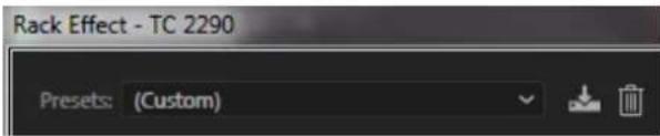
It is not recommended to use this as your primary method of saving presets as it has limited functionality and does not allow the saved presets to be transferred easily to other DAWs. Instead, we suggest using the included Preset section at the bottom of the window:
A single click on the PRESET window brings up a menu with several preset-related options. Recall a factory or user preset from the libraries, save the current preset, or create a new user preset with the 'Save as' option.
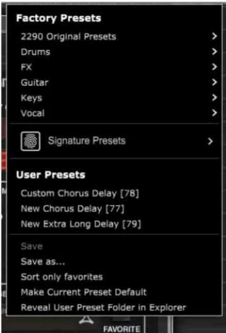
The presets menu is divided between a Factory Presets and a User Presets section.
The Factory Presets are built into the plug-in and cannot be overwritten, so if a factory preset is modified and you'd like to keep the changes, you need to save it as a user preset. User Presets can be edited and organized as you'd like.
The Factory Presets section includes a sub-section called Signature Presets. Signature Presets are custom-made presets designed by world-class artists and recording engineers. The library of signature presets is constantly being expanded, and you can check for more Signature Presets that might be available for download by accessing the Settings menu and selecting 'Signature Presets'.
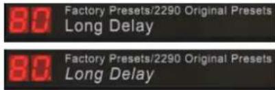
Factory and Signature presets have unique icons that appear next to the preset name.

When recalling a default or saved preset, the name will appear in plain text as shown. However, as soon as you make an alteration to any of the parameters in that preset, the text changes to italics to indicate a deviation. This is also indicated by a red dot after the preset number on the hardware unit and in the plug-in window. You can click in the PRESET window, then select the Save option, or discard the changes when you navigate away from that preset.
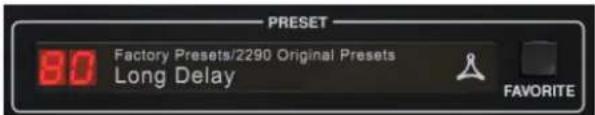
Presents can also be recalled from the hardware unit in the PRESET/SPEC section.
Pressing the preset UP or DOWN arrow buttons shifts the focus to that section, causing the green LED to flash. You can now press the UP and DOWN buttons to scroll through presets one slot at a time, or use the KEYBOARD to enter a specific preset number, followed by the ENTER button.
Favorite Preset
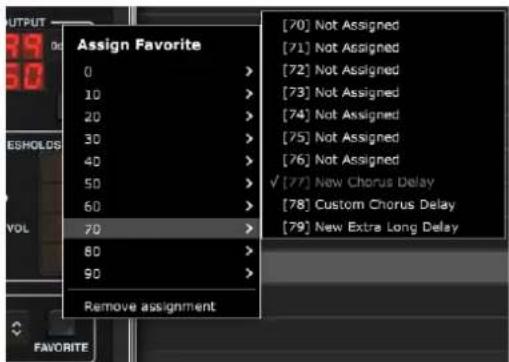
Creating your own presets will make them accessible from the Preset menu, but they will only appear in the list of 100 presets in the hardware unit if you set them as a favorite. This is done by assigning a favorite slot number to the preset using the Favorite menu. Click the FAVORITE button, then select one of the first 8 banks of 10 (presets 80-100 are default and cannot be saved over). Assign one of your custom presets to a favorite slot, then save the preset.


When a preset is assigned a favorite slot number:
The preset is part of the 100 presets that can be recalled on the hardware unit
- The favorite number will be displayed on the hardware unit when recalled
-
The favorite number will be locked so that other presets can not be assigned to the same favorite slot number. This is shown in the Favorite menu by graying out the number in question.
-
The favorite number will be displayed in brackets when you browse the presets menu

You can remove the favorite assignment by selecting the "Remove Assignment" feature in the Favorite menu, then saving the preset.
Sort only favorites
The 'Sort only favorites' option in the preset menu allows the UP/DOWN arrows on the hardware unit to scroll only through the favorites list. Otherwise, scrolling goes through all presets.
Make Current Preset Default
Selecting 'Make current preset default' will cause this preset to appear every time a new instance of the plug-in is created.
Reveal User Preset Folder in Explorer
To change the name of a preset, select 'Reveal User Preset Folder in Explorer' and modify the file name. This will open a Finder (Mac) or Explorer (PC) window where the user presets are stored. You can rename as well as delete, copy and paste presets. This allows you to share presets with other users online, simply pasting the new ones in this folder.
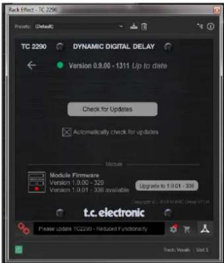
8. Software Updates
New versions of the software may be released to add new features and improve performance. Updates can be detected from the plug-in directly and can be installed after download from the website. See Chapter 2 for plug-in installation.
The hardware unit firmware will be included in each plug-in update.
If the 'Automatically check for updates' option is checked inside the update menu, the red dot will appear on the settings icon when a new plug-in is available.

Click the gear icon and select "Check for Updates" to perform a scan.
8.1 Hardware Unit Software Updates (optional)
After you have installed a new plug-in, the system will detect mismatched firmware and indicate a need for update via a small red dot on the gear icon.
Click the "Upgrade to x.x.xx" field to start the update. Progress will be indicated in the plug-in, and the Feedback LED on the hardware unit will flash.
1. Introduccion
Download and install the plug-in and connect the module Full Fuctionality
Disconnect Module 60 days... Reconnect Module
Processing, controls available for 60 days countdown
60 day count downLink to product page
Processing Only Full Fuctionality Restored
with store finder
In the MODULATION section, use the SELECT button to highlight the Dynamics (DYN) parameters. Ensure that the MOD button is engaged in the center PAN/DYN section.
Ducking Delay
A ducking delay uses the input signal to attenuate the delay signal, causing the echoes to stay "out of the way" while you're playing, but still allow the echo tails to be audible during gaps in your playing.
Press the WAVEFORM button until TRIG is selected. This selects the ducking effect.
Press the DEPTH UP or DOWN button to shift focus to this parameter. The green LED will flash above and the current value is displayed. This parameter controls how much the delay signal is attenuated. Lower the value for small amounts of attenuation, or raise it to make the effect almost inaudible while you're playing.
Press the SPEED UP or DOWN button to shift focus to this parameter. This controls the rate at which the attenuation is released. Lower values allow a longer period of time to pass after you stop playing before the echoes increase to their normal volume. Higher values let the echoes come in quickly.
Gated Delay
By pressing the REVERSE button in the PAN/DYN section, the ducking effect becomes a gated delay. Set this way, the effect will only be heard while you are playing, and will be attenuated when you stop.
Tremolo Effect
Press the WAVEFORM button until SINE or RAND are selected. This creates a tremolo effect where the volume of both the direct and delay signals are attenuated and then return to full volume, up and down at a constant rate (SINE only). Use the SPEED parameter to adjust the specific rate, and the DEPTH to adjust the amount of attenuation.
Custom Chorus Delay [78]
3.1 Activation when you have purchased the NATIVE version
Download and install the plug-in and connect the module Full Fuctionality
Disconnect Module 60 days... Reconnect Module
Each of these effects has its own MOD on/off button.
Custom Chorus Delay [78]
Proceed through the prompts to begin installation.
Download and install the plug-in and connect the module Full Fuctionality
with store finder
Disconnect Module 60 days... Reconnect Module
Processing, controls available for 60 days countdown
60 day count downLink to product page

Processing Only Full Fuctionality Restored
Custom Chorus Delay [78]
![TC ELECTRONIC TC2290DT - Custom Chorus Delay [78] - 1](/content/2026/03/558461/images/d896f57b47eafec8db3b4b32c4afcc67b2d830590f1e10005cd8432250114052.jpg)
Download and install the plug-in and connect the module Full Fuctionality
![TC ELECTRONIC TC2290DT - Custom Chorus Delay [78] - 2](/content/2026/03/558461/images/aaea38787e0129f597f8bf758a97a9ac5e4d9ee6b9f957fa8e145e79db00b6e8.jpg)
Disconnect Module 60 days... Reconnect Module
Processing, controls available for 60 days countdown
![TC ELECTRONIC TC2290DT - Custom Chorus Delay [78] - 3](/content/2026/03/558461/images/fd4751c2d9f16a62f6a092e816cc2614abafb72eba26cd0cc0e9dec7dc94f417.jpg)
Processing Only Full Fuctionality Restored
![TC ELECTRONIC TC2290DT - Custom Chorus Delay [78] - 4](/content/2026/03/558461/images/cde45fa52354642822cc56343df0ec0b5dd61f80ea915332ec3e7d7cf978ea93.jpg)
with store finder
DLY MOD - Delay ENV e TRIG waveforms.
PAN MOD - Formas de onda Pan ENV e TRIG.
Custom Chorus Delay [78]
![TC ELECTRONIC TC2290DT - Custom Chorus Delay [78] - 5](/content/2026/03/558461/images/dbff150f8366e9e4dfd580804c602c9386fbc872f88e90f3bebc4309d935c56f.jpg)
Download and install the plug-in and connect the module Full Functionality
with store finder
![TC ELECTRONIC TC2290DT - Custom Chorus Delay [78] - 6](/content/2026/03/558461/images/05b138fe950cb6892ee429ec182d1cef55c7bfc80b1fd7d00f0e1bd972db547a.jpg)
Disconnect Module 60 days... Reconnect Module
Processing, controls available for 60 days countdown
60 day count downLink to product page
![TC ELECTRONIC TC2290DT - Custom Chorus Delay [78] - 7](/content/2026/03/558461/images/4742c31cecbfd287af95ab05174f3866d306b352e856d325326e1de6d1d7d125.jpg)
![TC ELECTRONIC TC2290DT - Custom Chorus Delay [78] - 8](/content/2026/03/558461/images/aa243ad8d675decff54a783209368a0073a7b061c898f8bcb685fa4cf3405ff6.jpg)
Processing Only Full Fuctionality Restored
![TC ELECTRONIC TC2290DT - Custom Chorus Delay [78] - 9](/content/2026/03/558461/images/1c874b2a9a8991739daba80c03d9426cde7fbe2bd766557b6ac3d7af1cea63b3.jpg)
User Presets Custom Chorus Delay [78]
Stap 1: installer iLok
Stap 1: installer iLok
Download and install the plug-in and connect the module Full Fuctionality
Disconnect Module 60 days... Reconnect Module
Processing, controls available for 60 days Processing Only Full Fuctionality Restored
with store finder
60 day count downLink to product page
4.6 Primaire en secundaire bedieningselementen
Press the WAVEFORM button until SINE or RAND are selected. This creates a tremolo effect where the volume of both the direct and delay signals are attenuated and then return to full volume, up and down at a constant rate (SINE only). Use the SPEED parameter to adjust the specific rate, and the DEPTH to adjust the amount of attenuation.
Compressor/expandereffect
The TC2290 can be used as an autopanner on the direct signal only by setting the MIX control in the plug-in window to 0.
7.Voorinstellingen
Custom Chorus Delay [78]
2. Plug-in installation
Besök www.tcelectronic.com/tc2290-dt/support/ für att ladda ner installationsfilen. Insticksprogrammet kraver antingen en iLok-licens (levereras när du köper NATIVE-versionen) aller TC2290 DT Desktop Controller (när du köper DT Desktop Controller-versionen) aller en iLok-provlicens. Alla parametr ar tillgangliga i plug-in och de fleta ar tillgangliga på DT Desktop Controller.
Download and install the plug-in and connect the module Full Fuctionality
with store finder
Disconnect Module 60 days... Reconnect Module
Processing, controls available for 60 days countdown
60 day count downLink to product page
Processing Only Full Fuctionality Restored
User Presets Custom Chorus Delay [78]
![TC ELECTRONIC TC2290DT - User Presets Custom Chorus Delay [78] - 1](/content/2026/03/558461/images/fbab72496318ae9725a026729fb09e63ad26c8755d892c8f8b1f2c449ced7f03.jpg)
Download and install the plug-in and connect the module
Full Fuctionality
with store finder
![TC ELECTRONIC TC2290DT - User Presets Custom Chorus Delay [78] - 2](/content/2026/03/558461/images/654555d61621e5adb79c4414990d1088ce10697f1a92d5b2c226d72ea4ab9521.jpg)
Disconnect Module 60 days... Reconnect Module
Processing, controls available for 60 days countdown
60 day count downLink to product page
![TC ELECTRONIC TC2290DT - User Presets Custom Chorus Delay [78] - 3](/content/2026/03/558461/images/1cc538a8b194961b199ae122884efe6a343f84624af4ec1ba9638c268e368f9e.jpg)
![TC ELECTRONIC TC2290DT - User Presets Custom Chorus Delay [78] - 4](/content/2026/03/558461/images/4ccbb70628daf735318dc6a1bda69c6e31ee6ee333a893da83843657c2933889.jpg)
Processing Only Full Fuctionality Restored
![TC ELECTRONIC TC2290DT - User Presets Custom Chorus Delay [78] - 5](/content/2026/03/558461/images/729aeae7483e2d53050754d61476222b015570a2ad55e4156cffc654793e82da.jpg)
Custom Chorus Delay [78]
Sample rates 44.1, 48, 88.2, 96, 176.4, 192 kHz
Software Support
Operating systems Mac OS X 10.13 Sierra or above,
Windows 7 or above
Drivers No additional drivers required,
uses standard USB HID drivers
Plugin formats AAX-native, Audio Units,
VST2.4,VST3.64bit
USB Connection (DT version)
Type USB 2.0, type micro-B
Power (DT Version)
Power supply USB bus powered
Power consumption Max. 2.5 W
Physical (DT version)
Dimensions (HxWxD) 43 x 109 x 135 mm (1.7 x 4.3 x 5.3")
Weight 0.4kg (0.88 lbs)
EN
10. Signal Flow Diagram
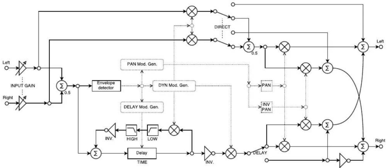
DELAY Mod. Control
PAN Mod. Control
DYN Mod. Control
INPUT:
DELAY ON
INPUT:
INPUT:
MODULATION:
SPEED
PAN
SPEED
DEPTH
WAVEFORM
MODULATION:
DEPTH
DELAY:
MOD.
DEPTH
DYN:
SPEC:
9-INV DLY MOD
MOD.
SPEC:
10 - DLY MOD Threshold
8-DEEP MOD
SPEC:
13-DYN FB
FEDERAL COMMUNICATIONS COMMISSION COMPLIANCE INFORMATION
TC Electronic
TC2290
Responsible Party Name: Music Tribe Commercial NV Inc.
Address: 5270 Procyon Street,
Las Vegas NV 89118, United States
Phone Number: +1 702 800 8290
TC2290
This equipment has been tested and found to comply with the limits for a Class B digital device, pursuant to part 15 of the FCC Rules. These limits are designed to provide reasonable protection against harmful interference in a residential installation. This equipment generates, uses and can radiate radio frequency energy and, if not installed and used in accordance with the instructions, may cause harmful interference to radio communications. However, there is no guarantee that interference will not occur in a particular installation. If this equipment does cause harmful interference to radio or television reception, which can be determined by turning the equipment off and on, the user is encouraged to try to correct the interference by one or more of the following measures:
- Reorient or relocate the receiving antenna.
- Increase the separation between the equipment and receiver.
- Connect the equipment into an outlet on a circuit different from that to which the receiver is connected.
- Consult the dealer or an experienced radio/TV technician for help.
This device complies with Part 15 of the FCC rules. Operation is subject to the following two conditions:
(1) this device may not cause harmful interference, and
(2) this device must accept any interference received, including interference that may cause undesired operation.
Important information:
Changes or modifications to the equipment not expressly approved by Music Tribe can void the user's authority to use the equipment.

Hereby, Music Tribe declares that this product is in compliance with Directive 2014/30/EU, Directive 2011/65/EU and Amendment 2015/863/EU, Directive 2012/19/EU, Regulation 519/2012 REACH SVHC and Directive 1907/2006/EC.
Full text of EU DoC is available at https://community.musictribe.com/
EU Representative: Music Tribe Brands DK A/S
Address: Ib Spang Olsens Gade 17, DK - 8200 Aarhus N, Denmark
UK Representative: Music Tribe Brands UK Ltd St George's House 215-219 Chester
Road, Manchester, Greater Manchester, England, M15 4JE