Reverb Twentyfour - Guitar Effects TC ELECTRONIC - Free user manual and instructions
Find the device manual for free Reverb Twentyfour TC ELECTRONIC in PDF.

User questions about Reverb Twentyfour TC ELECTRONIC
0 question about this device. Answer the ones you know or ask your own.
Ask a new question about this device
Download the instructions for your Guitar Effects in PDF format for free! Find your manual Reverb Twentyfour - TC ELECTRONIC and take your electronic device back in hand. On this page are published all the documents necessary for the use of your device. Reverb Twentyfour by TC ELECTRONIC.
USER MANUAL Reverb Twentyfour TC ELECTRONIC
natural_image
Collage of five interior scenes: stage performance, outdoor venue with spotlights, concert stage with blue lighting, person watching, and modern living room with TV (no visible text or symbols)REVERB TWENTYFOUR
High-Definition 19 Rack Unit with 24 Channels of Simultaneous Uncorrelated Reverb Supporting Extreme Surround Formats
Owner's Manual

text_image
RUNNING NET DIPARATED SYNC RESET REVERB TWENTYFOUR TC RATESHORN REVERS tc electronic
Table of Contents
Important Safety Instructions .... 3
Legal Disclaimer 3
Limited warranty....3
1. Introduction......4
2. TC Icon software installation....5
2.1 Software Installation....5
2.2 Installing the TC Icon software on a PC....5
2.3 Installing the TC Icon software on a Mac......6
2.4 Running the TC Icon software 7
2.5 Updating the Reverb TwentyFour firmware......8
3. Controls and Connectors 9
4. Overview 11
5. Setting up....12
5.1 Networking basics and troubleshooting .... 12
6. Quick Setup....14
7. Basic operation with the TC Icon software......15
7.1 TC Icon interface.... 15
7.2 System/ Status page 17
7.3 System/ I/O....18
7.4 System/ Setup/ Version....18
7.5 System/ Setup/ Net 19
7.6 System/ Setup/ Update 19
7.7 System/ Remote 20
7.8 E1-3 page....20
8. Using the Library 21
8.1 Library – Recall....21
8.2 Library – Store....23
8.3 Library – Delete....24
8.4 Library – Bank page....25
9. TC Icon Setup 26
9.1 Info page 26
9.2 Devices page....26
9.3 Security page 27
9.4 UI page 27
9.5 Color page....28
10. Using Reverb TwentyFour....29
11. Main page 32
11.1 Levels Section....32
11.2 Pre Delay Section....32
12. Grid page....33
13. Setup page 34
13.1 Grid Setup section....34
13.2 Group 1 section....34
14. Rev page 35
14.1 Reverb Setup section 35
14.2 Reverb Color section....35
15. Trim page....36
16. Factory presets ...... 37
16.1 Scene Presets 37
16.2 Routing Presets....38
16.3 Engine Presets....40
17. System/ Remote 41
17.1 Remote - GPI 1 - Scene Recall section....41
17.2 Remote - Calibration....42
17.3 GPIO Technical specifications....43
18. Acoustics Enhancement......45
19. Specifications......47
EN
Important Safety Instructions

text_image
CAUTION RISK OF ELECTRIC SHOCK! DO NOT OPEN! ATTENTION RISQUE D'ÉLECTROCUTION! NE PAS OUVRIR!
Terminals marked with this symbol carry electrical current of sufficient magnitude to constitute risk of electric shock.
Use only high-quality professional speaker cables with 14 " TS or twist-locking plugs pre-installed. All other installation or modification should be performed only by qualified personnel.
This symbol, wherever it appears, alerts you to the presence of uninsulated dangerous voltage inside the
enclosure - voltage that may be sufficient to constitute a risk of shock.

This symbol, wherever it appears, alerts you to important operating and maintenance instructions in the
accompanying literature. Please read the manual.

Caution
To reduce the risk of electric shock, do not remove the top cover (or the rear section).
No user serviceable parts inside. Refer servicing to qualified personnel.

Caution
To reduce the risk of fire or electric shock, do not expose this appliance to rain and
moisture. The apparatus shall not be exposed to dripping or splashing liquids and no objects filled with liquids, such as vases, shall be placed on the apparatus.

Caution
These service instructions are for use by qualified service personnel only.
To reduce the risk of electric shock do not perform any servicing other than that contained in the operation instructions. Repairs have to be performed by qualified service personnel.
- Read these instructions.
- Keep these instructions.
- Heed all warnings.
- Follow all instructions.
- Do not use this apparatus near water.
- Clean only with dry cloth.
- Do not block any ventilation openings. Install in accordance with the manufacturer's instructions.
-
Do not install near any heat sources such as radiators, heat registers, stoves, or other apparatus (including amplifiers) that produce heat.
-
Do not defeat the safety purpose of the polarized or grounding-type plug. A polarized plug has two blades with one wider than the other. A grounding-type plug has two blades and a third grounding prong. The wide blade or the third prong are provided for your safety. If the provided plug does not fit into your outlet, consult an electrician for replacement of the obsolete outlet.
- Protect the power cord from being walked on or pinched particularly at plugs, convenience receptacles, and the point where they exit from the apparatus.
- Use only attachments/accessories specified by the manufacturer.

natural_image
Silhouette of a person pushing a cart with a roller, enclosed in a circular frame (no text or symbols)- Use only with the cart, stand, tripod, bracket, or table specified by the manufacturer, or sold with the apparatus. When a cart is used, use caution when moving the cart/apparatus combination to avoid
injury from tip-over.
- Unplug this apparatus during lightning storms or when unused for long periods of time.
- Refer all servicing to qualified service personnel. Servicing is required when the apparatus has been damaged in any way, such as power supply cord or plug is damaged, liquid has been spilled or objects have fallen into the apparatus, the apparatus has been exposed to rain or moisture, does not operate normally, or has been dropped.
- The apparatus shall be connected to a MAINS socket outlet with a protective earthing connection.
- Where the MAINS plug or an appliance coupler is used as the disconnect device, the disconnect device shall remain readily operable.

- Correct disposal of this product: This symbol indicates that this product must not be disposed of with household waste, according to the WEEE Directive (2012/19/EU) and your national law. This product should be taken
to a collection center licensed for the recycling of waste electrical and electronic equipment (EEE). The mishandling of this type of waste could have a possible negative impact on the environment and human health due to potentially hazardous substances that are generally associated with EEE. At the same time, your cooperation in the correct disposal of this product will contribute to the efficient use of natural resources. For more information about where you can take your waste equipment for recycling, please contact your local city office, or your household waste collection service.
- Do not install in a confined space, such as a book case or similar unit.
-
Do not place naked flame sources, such as lighted candles, on the apparatus.
-
Please keep the environmental aspects of battery disposal in mind. Batteries must be disposed-of at a battery collection point.
- Use this apparatus in tropical and/or moderate climates.
LEGAL DISCLAIMER
MUSIC Group accepts no liability for any loss which may be suffered by any person who relies either wholly or in part upon any description, photograph, or statement contained herein. Technical specifications, appearances and other information are subject to change without notice. All trademarks are the property of their respective owners. MIDAS, KLARK TEKNIK, LAB GRUPPEN, LAKE, TANNOY, TURBOSOUND, TC ELECTRONIC, TC HELICON, BEHRINGER, BUGERA and DDA are trademarks or registered trademarks of MUSIC Group IP Ltd. © MUSIC Group IP Ltd. 2017 All rights reserved.
LIMITED WARRANTY
For the applicable warranty terms and conditions and additional information regarding MUSIC Group's Limited Warranty, please see complete details online at music-group.com/warranty.
EN
EN
1. Introduction
About this manual
Read this manual to learn how to install and use your TC Electronic Reverb TwentyFour multichannel reverb unit.
This manual is only available in PDF format from the TC Electronic website.
To get the most from this manual, please read it from start to finish, or you may miss important information.
To download the most current version of this manual, visit the web page tcelectronic.com/support/manuals/
Getting support
If you still have questions about your TC Electronic product after reading its manual, please get in touch with TC Support:
tcelectronic.com/support/
2. TC Icon software installation
2.1 Software Installation
The Reverb TwentyFour unit has no physical controls on the front or rear panel. It is controlled via the rear panel Ethernet connections either by a PC or Mac computer running the free TC Icon software available from our website, or by using the optional TC Icon remote control, available separately.
When you are working with a system involving one or multiple Reverb TwentyFour units, you are interacting with two types of software:
2.1.1 TC Icon Software:
TC Icon is a software application that you install on the computer(s) which you are using to access, configure, operate and update the Reverb TwentyFour unit(s).
TC Icon software is available for Microsoft Windows and Mac OS X operating systems.
TC Icon software is free and can be installed on multiple computers.
Downloading and installing TC Icon software is described in this section of the manual.
2.1.2 TC Reverb TwentyFour Firmware:
Reverb TwentyFour firmware is the software internally installed on the Reverb TwentyFour. Every unit comes pre-installed with the most current firmware version available at the time of production. You can download newer versions of firmware from the TC website. Firmware updates will contain bug fixes and/or new features.
Reverb TwentyFour firmware updates are free.
Use the TC Icon software installed on your computer (see above) to transfer firmware to your Reverb TwentyFour unit(s).
Downloading and installing the Reverb TwentyFour firmware updates is described in "System/Setup/Update" on page 19.
Please check our website often for any updates to the software and firmware. You should keep both the TC Icon software running on your computer and the Reverb TwentyFour firmware up to date. Using the latest software and firmware versions ensures that you benefit from any bug fixes and the latest features.
The following procedures show how to obtain and run the TC Icon software for PC or Mac computers.
2.2 Installing the TC Icon software on a PC
Please go to www.tcelectronic.com and locate the Reverb TwentyFour section or TC Icon section (as it has the same software). Alternatively, you can visit the support\software section and locate the available software downloads for the Reverb TwentyFour or the TC Icon remote unit.
Please note, the screenshots that follow, are of the Reverb TwentyFour section of the website.
- Click on the button to select the Windows version of the software.
Firmware
+ Show version history

Reverb TwentyFour Firmware Windows & Mac - Version 1.0.00_3421-1.34 MB
Released: Tuesday May 29, 2017
+ Show previous versions
TC Icon Software
+ Show version history

Reverb TwentyFour TC Icon Software Windows - Version 8_4_00_30457 - 1.84 MB
Released: Tuesday May 29, 2017

Reverb TwentyFour TC Icon Software Mac Version 8 4 00 30457 - 5.9 MB
Released: Tuesday May 29, 2017
- Enter your e-mail address, press "Submit" and a link to the download will be sent to you very shortly. If you wanted to be notified of updates and news, you can click on the small box below where you enter your address.
Please enter your email address to receive a download link for the software.
Keep Me Informed with Updates and News
Submit
Cancel
• The website will confirm that an e-mail has been sent to your address.

Please check your email. We have just sent you a download link.
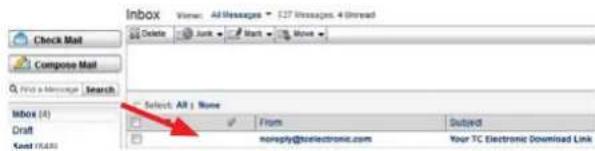
- Open your e-mail application and check for the new e-mail we sent you:
text_image
Inbox View: Add Messages - 127 Messages, 4 (Read) Delete Junk Mark Move Check Mail Compose Mail Find a Message Search Inbox (A) Draft Send (E) Select All | None From Outard noneply@telecronic.com Your TC Electronic Download Link- Open the e-mail and click on the link provided. The download will begin.
EN
• Save the zipped file in a convenient location on your PC.

text_image
Opening icon_8_3_00_30366_windows.zip You have chosen to open: icon_8_3_00_30366_windows.zip which is: Compressed (zipped) Folder (1.8 MB) from: http://cdn-downloads.tcelectronic.com What should Firefox do with this file? Open with Windows Explorer (default) Save File Do this automatically for files like this from now on. OK Cancel- Unzip the zipped file and save the Icon.exe executable file in a convenient location on your PC.
2.3 Installing the TC Icon software on a Mac
Please go to www.tcelectronic.com and locate the Reverb TwentyFour section or TC Icon section (as it has the same software). Alternatively, you can visit the support\software section and locate the available software downloads for the Reverb TwentyFour.
Please note, the screenshots that follow, are of the Reverb TwentyFour section of the website.
- Click on the button to select the Mac version of the software.
Firmware
+ Show version history

Reverb TwentyFour Firmware Windows & Mac - Version 1_0_00_3421 - 1.34 MB
Released: Tuesday May 29, 2017
+ Show previous versions
TC Icon Software
+ Show version history

Reverb TwentyFour TC Icon Software Windows - Version 8_1_00_30457 - 1.84 MB
Released: Tuesday May 29, 2017

text_image
Reverb TwentyFour TC Icon Software Mac - Version 8_4_00_30457 - 5.9 MBReleased: Tuesday May 29, 2017
- Enter your e-mail address, press "Submit" and a link to the download will be sent to you very shortly. If you wanted to be notified of updates and news, you can click on the small box below where you enter your address.

text_image
Please enter your email address to receive a download link for the software. Keep Me Informed with Updates and News Submit Cancel• The website will confirm that an e-mail has been sent to your address.

Please check your email. We have just sent you a download link.
- Open your e-mail and check for the new e-mail we sent to you:

text_image
Organize Open Share with Burn New Folder Favorites Desktop Name: Data modified Type: Size Icon 1:25/2024-0.15 AM Application 6,097 KB• Open the e-mail and click on the link provided.
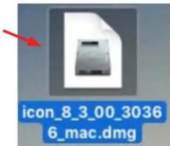
• Save the mac.dmg file in a convenient location on your Mac.
text_image
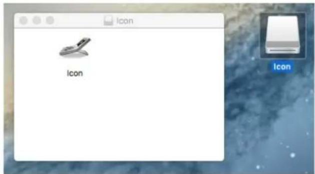
icon_8_3_00_3036 6_mac.dmg- Click on the file and the Icon folder and drive will appear.
text_image
Icon Icon- Note, if you have trouble at this stage, for example, the following screen appears: "Icon can't be opened because it is from an unidentified developer," then check your system preferences.
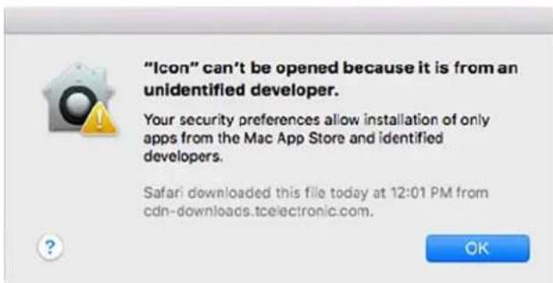
text_image
"Icon" can't be opened because it is from an unidentified developer. Your security preferences allow installation of only apps from the Mac App Store and identified developers. Safari downloaded this file today at 12:01 PM from cdn-downloads.tcelectronic.com. OK• Then select OPEN to accept and trust the file from tcelectronic.com.

text_image
"Icon" is an application downloaded from the Internet. Are you sure you want to open it? Safari downloaded this file today at 12:01 PM from cdn downloads.tcelectronic.com. Cancel Show Web Page Open- When this is successful, then drag the Icon into your Applications folder.

text_image
tadger1 Name Macintosh HD Applications Library System User Information Users Network Remote Disc Icon- You can then copy it from the applications folder onto your toolbar for easy access.

text_image
MAY 17- If you experience technical problems during software download or installation, please ask a person with administrator privileges on your computer for assistance.
- To prevent the App from going to sleep and to ensure smoother operation in certain situations, right-click on the App and choose "prevent App Nap."
2.4 Running the TC Icon software
- Make the connections to the Reverb TwentyFour unit, including the Ethernet connection to the same Network as your computer. When all connections are made, apply AC power to the Reverb TwentyFour.
- On a PC, locate and double-click on the extracted icon.exe file to run the executable file.

natural_image
Icon illustration of a mobile phone with a red arrow pointing to it, labeled 'Icon' below (no text or symbols on the device itself)• On a Mac, click on the TC Icon.

text_image
MAY 17- The TC Icon software will run, and it will then try to locate any TC devices that are connected to your Ethernet network. If a TC device is not found, then the following screen will appear:
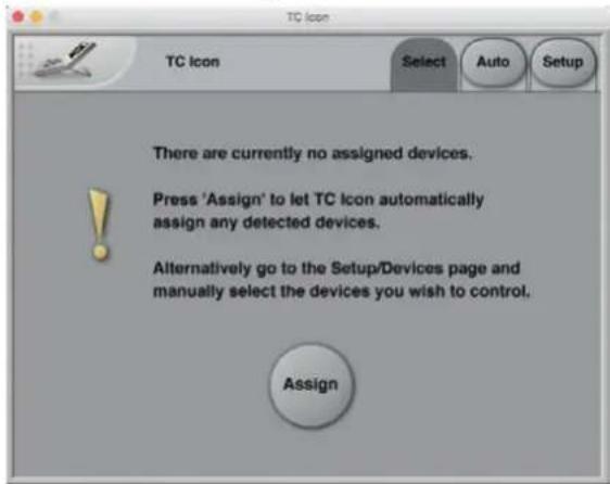
text_image
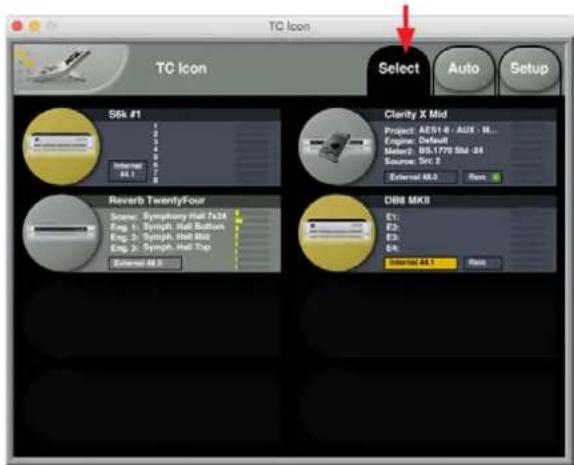
TC Icon Select Auto Setup There are currently no assigned devices. Press 'Assign' to let TC Icon automatically assign any detected devices. Alternatively go to the Setup/Devices page and manually select the devices you wish to control. Assign- If TC devices are found on the network, then the TC Icon screen will be something similar to this example, where 4 different TC Electronic devices are found. Click on the Reverb TwentyFour area to select it for editing and controlling:

text_image
TC Icon Select Auto Setup S6k #1 Internal: 44.1 Clarify X Mid Project: AESI-8 - AUX - M_ Engine: Default Source: 05.177y Bkt-24 Source: Tn5.2 External: 44.1 Reverb TwentyFour Sequence: Symphony Hall 7/34 Eng. 1: Symphony Hall Business Eng. 2: Symphony Hall Top Eng. 3: Symphony Hall Top External: 44.1 DBB MKII E1: E2: E3: E4: Internal: 44.1 OK
- Note that the TC Icon software runs on other TC units, not just the Reverb TwentyFour, so it may find other units in your system, and you can select which unit you would like to control at any given time.
- If a connection to the TC device cannot be established, please refer to "Networking basics and troubleshooting" on page 12.
2.4.1 Updating TC Icon software (PC)
To update the TC Icon software on your computer when a newer version is released:
- Quit the TC Icon software if it is currently running on your PC.
- Download and extract the newer version as described previously and replace the currently installed version by copying the newer version over it.
2.4.2 Updating TC Icon software (Mac)
To update the TC Icon software on your computer when a newer version is released,
- Quit the TC Icon software if it currently running on your Mac.
- Download and extract the newer version as described previously and replace the currently installed version by copying the newer version over it.
- You can now unmount (eject) the disk image by right-clicking it and selecting "Eject" from the context menu.
2.5 Updating the Reverb TwentyFour firmware
The TC Icon software user interface on your computer includes an area where the Reverb TwentyFour firmware can be updated, and the various firmware and software version numbers can be displayed. This is described in "System/Setup/Update" on page 19.
- Regulatory check the TC Electronics website for updates to the Reverb TwentyFour firmware, and download the updated files from the same web pages as described above for the TC Icon software downloads.
- If a newer version of the firmware is available, download it onto your computer (PC or Mac) from the website, by clicking the firmware button.
Firmware
+ Show version history


Reverb TwentyFour Firmware
Windows & Mac - Version 1_0_00_3421 - 1.34 MB
Released: Tuesday May 29, 2017
+ Show previous versions
TC Icon Software
+ Show version history

Reverb TwentyFour TC Icon Software
Windows - Version 8_4_00_30457 - 1.84 MB
Released: Tuesday May 29, 2017

Reverb TwentyFour TC Icon Software
Mac - Version 8 4 00 30457 - 5.9 MB
Released: Tuesday May 29, 2017
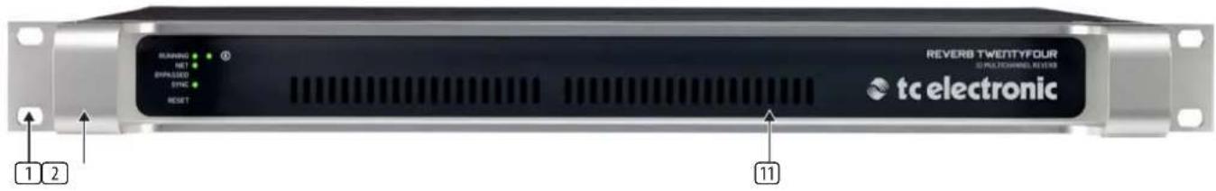
3. Controls and Connectors
EN
text_image
RUNNING NET IMPASSO SYNC RESET REVERB TWENTYFOUR 3D MULTICHNIC REVERB tc electronic 1 2 11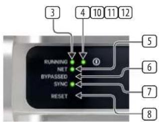
text_image
3 4 10 11 12 RUNNING NET BYPASSED SYNC RESET ① 5 6 7 8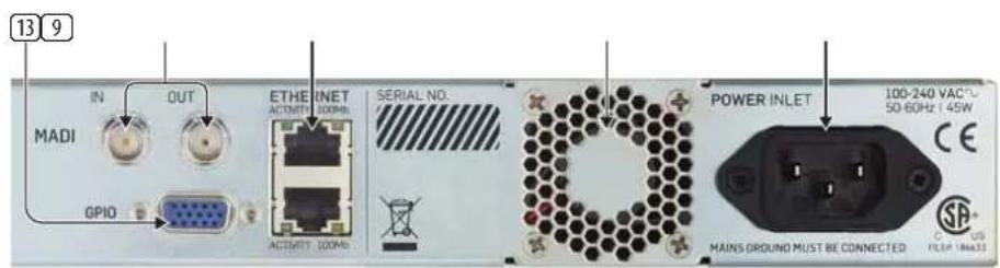
text_image
13 9 IN MADI OUT GPIO ETBE INET ACTIVITY: 100MHz ACTIVITY: 100MHz SERIAL NO. POWER INLET 100-240 VAC 50-60Hz 45W CE MAINS GROUND MUST BE CONNECTED US FILEP 1846321 RACK MOUNT EARS – allow the unit to be mounted into a standard 1U rack. Be kind and use washers and the correct rack screws to hold the unit securely in your rack.
2 HANDLES – these allow the unit to be carried and easily pulled in and out of the rack.
3 RUNNING LED – this LED indicates the status of the Reverb TwentyFour:
| Running Led Status | TC Icon message | |
| Off | Startup until all processors are running | N/A |
| Green | Startup completed, and the unit is ready | Running OK |
| Red System Error | Not running, system error |
4 POWER LED – this is Green when AC power is applied to the unit.
5 NET LED – The Net LED indicates the status of the network connection to a computer running TC Icon software or a hardware TC Icon device.
| Net Led Status TC Icon message | ||
| Off | No computer or TC icon device connected | N/A |
| Green | One or more TC Icons or computers connected | Net – This Icon(1),2 Icons/ Apps(2) ...8 Icons/Apps(8)Running OK |
| Off/Green, Yellow, Red | Frame identification – see "Frame identification parameter" on page 17 | Net LED will blink various colors as set by the TC Icon software, so you can easily identify the Reverb TwentyFour when operating multiple units |
6 BYPASSED LED – this LED will turn on when the Reverb TwentyFour is in the BYPASS mode, as set by the TC Icon controller software on your computer (see page 20), or by using the hardware TC Icon remote device. No reverb will be added to any of the audio inputs when the unit is in Bypass mode.
7 SYNC LED – this LED indicates if synchronization to the signal source has been achieved.
| Sync Led Status TC Icon message | ||
| Off | Startup until I/Os are up and running | N/A |
| Green | Sync OK + all inputs OK (No sample slips/repeats) | Inputs OK |
| Yellow | Slip/repeat observed | Input Slip |
| Red | No valid clock available | No Clock |
⑧ RESET BUTTON – The Reset button on the front panel can be used to reset the IP address of a Reverb TwentyFour unit, or to reset Ethernet communication between the unit and a computer when a communication error has occurred.
Resetting the IP address
- On the rear panel, make a note of the unit's serial number and write it down here:
- Switch off the Reverb TwentyFour unit by disconnecting AC power to the unit.
- Gently insert a straightened paper clip or a similar object into the small "Reset" hole on the front panel, until it touches the button behind the panel, and then keep it holding down gently.
- Reconnect the AC power to the unit, while still holding the straightened paper clip onto the Reset button.
- The Reverb TwentyFour unit will then boot using its default IP address as follows: 192.168.1.[xx], where [xx] is the last two digits of the device's serial number as printed on the rear panel.
192168.1__
EN
Resetting Ethernet communication
- To reset Ethernet communication between the Reverb TwentyFour and a computer during operation, proceed as follows:
- During operation, gently insert a straightened paper clip or a similar object into the "Reset" hole on the front panel until it touches the button behind the panel, and press the button down for approximately 5 seconds until the LEDs start blinking.
• This will reset Ethernet communication without interrupting audio streams.
Rear Panel
⑨ MADI INPUT AND OUTPUT – the Reverb TwentyFour has one BNC MADI input that connects to the MADI output of your external equipment. Use a 75 Ohm impedance cable to make the connections. The Reverb TwentyFour accepts 28, 32, 56, or 64 channels of MADI input.
- The BNC MADI output connects to the MADI input of your external MADI equipment. The Reverb TwentyFour processes and adds reverb to a maximum of 24 channels per unit, and the other inputs channels are bypassed.
• See the specification table on page 47 for more details of the MADI input and outputs.
⑩ ETHERNET CONNECTORS – these two 32-bit Ethernet interfaces are fully compliant with the IEE 802.3u standard, supporting 10 and 100 Mbit/s (100Base-TX ports).
- Connect a computer running TC Icon software or a hardware TC Icon device to one of these ports using a "straight-through" cable with 8P8C modular connectors (RJ45). A "crossover" type cable is not required.
- The Ethernet ports are used exclusively for connecting a controller (namely a computer running TC Icon software, or the hardware TC Icon device). No audio signals are transmitted for processing over these Ethernet ports.
⑪ FAN VENTILATION – do not block the ventilation slots at the front or rear, as this will reduce or block the airflow within the unit.
⑫ AC POWER INPUT – the unit is provided with one AC power input socket that accepts input voltages from 100 to 230 Volts AC at 50/60 Hz. Do not make connections to AC power until all connections to and from the Reverb TwentyFour have been made. The unit has no AC power switch and so it will be on whenever the AC power is applied to this AC input, and the Power LED (item 4) will be on.
13 GPIO PORT – this General Purpose Input/Output port can be used to connect a controller to remotely control various Reverb TwentyFour features.
- For more information on GPIO, see "System/Remote" on page 41 and "GPIO Technical Specifications" on page 43.
4. Overview
Thank you for choosing a Reverb TwentyFour. This remarkable device has the following features:
- Pristine high-definition multichannel reverb in 19" rack format, that lets you create and manipulate reverb for up to 24 channels simultaneously, so you can deliver powerful content for even the most extreme surround formats.
- Process any mono or higher signal source to create content with as many output channels as you want.
- Flexible and seamless audio routing with 64 MADI channels of input and output on-board.
- Manipulate spaciousness for countless channels faster, better and over a wider range than ever before, letting you convey space more credibly than is possible with a microphone array in a real room.
- Fully downmix-compatible to let you render down from high channel formats gracefully, without introducing phasing artifacts or altering mix balance.
- Compatible with modern high-channel-count workflows, such as NHK Super Hi-vision, Dolby Atmos, Barco Auro and of custom installations where multichannel, high-performance audio is a key element.
- Power Correction maintains your direct-sound-to-reverb ratio while you do mix changes and experiment with decay time settings, saving significant re-trimming work.
- Truly make the most of extra discrete channels with reverb color to help you convey spaces imaginatively in multichannel format.
- New envelopment technique overthrows convention so that input signals already containing spatial information can be regarded as a perfect input source, enabling you to add significant reverb to them.
- Grid page provides quick and easy access to make and adjust spaces for many channels simultaneously.
- Main setup options let you manipulate channel groups to quickly offset balances and timing.
- As well as creating more credible envelopment from many loudspeaker channels than is achievable using a microphone array in a real room, the Reverb TwentyFour mixes-down perfectly and predictably, like other decorrelated signals.
- An important development goal of the Reverb TwentyFour has been not to waste loudspeakers – the more discrete channels there are, the better the envelopment will be.
- The inputs and outputs of the Reverb TwentyFour can be distributed quite flexibly.
Solid foundations
TC's involvement with high quality digital audio dates back to the mid-eighties. Our commitment to digital excellence has continued over the years with equipment for the music, film and mastering industries.
Many years of experience with analog and digital audio production and the know-how of skilled engineers: this is the foundation on which this product was built. From the purist and quality-conscious hardware engineers to the software writers, some of whom were involved with designing the MPEG codecs: The team who have worked on the Reverb TwentyFour forms a competent, non-dogmatic design group ready to take film audio production to the next level.
We are confident you will value the result of their hard work.
Basic concepts and operation
The Reverb TwentyFour is equipped with three so-called engines E1, E2, and E3, running the reverb algorithms.
As you can easily see, Reverb TwentyFour is a "headless system" — it has no front panel controls (with the exception of the Reset button).
Reverb TwentyFour is operated using the TC Icon software, which you can download from the TC Electronic website as described previously.
You can use the same version of the TC Icon software to operate our other products in film, audio and production, such as the System 6000.
Accordingly, a significant part of this manual covers operating Reverb TwentyFour using TC Icon software running on a standard computer, and the screen shots you will see are taken from the OS X or Windows versions of this software.
Reverb TwentyFour offers a variety of ways to engage or disengage audio processing. Processing may be invoked automatically, depending on format, level, physical inputs etc., while remote control can be achieved via Ethernet, and GPIO. When setting up the device, make sure to only engage the methods you wish to use. For example, if the GPI inputs are not used, make sure to disable the respective input.
Please invest some time in learning TC Icon's basic concepts – you will benefit from it when you are operating systems that may include many networked TC signal processors.
Reverb TwentyFour and MADI
Reverb TwentyFour is available in just one hardware version: with MADI input and output.
There are up to 64 MADI inputs and outputs, and a maximum of 24 channels can be processed by the Reverb TwentyFour at any given time. The remaining channels of MADI input will pass right through.
We assume that you have a good working knowledge of MADI, including external audio equipment that outputs MADI into the Reverb TwentyFour, and equipment that inputs MADI from the Reverb TwentyFour. The MADI standard is not discussed in this manual, although the specification table on page 47 shows MADI technical details.
Reverb TwentyFour presets
Reverb TwentyFour comes with ready-to-use presets based on international standards. More presets will be made available as part of software updates from the TC website. These presets are based on information from engineers around the world.
A good look at the available factory presets will help you see the flexibility offered by the Reverb TwentyFour, and what can be achieved. Please see section 16 on page 37 for more details of the factory presets. You can use the factory presets as a basis for creating your own user presets.
If you feel that an important preset is missing or that a given preset does not work as it should, please get in touch with TC Electronic technical support:
tcelectronic.com/support/
EN
5. Setting up
Reverb TwentyFour can be used in a variety of configurations and setups. However, as up to 8 TC production and broadcast processors in your system can be controlled from a single computer running TC Icon software, even large and complex setups are basically operated in the same manner as the basic setup described in this chapter.
5.1 Networking basics and troubleshooting
You may setup and operate your Reverb TwentyFour in a simple networking environment — where you can connect a computer and one Reverb TwentyFour directly using a standard Ethernet cable —, or your system may be more complex, involving several Reverb TwentyFour units and other TC devices.
Either way, you are operating a system based on TCP/IP – the same protocol suite the Internet is built on. Accordingly, you need to follow basic networking procedures when setting up your system.
It is most likely that a standard computer running the TC Icon software will detect a Reverb TwentyFour "out of the box" without any problems. However, if it doesn't, there is most likely a subnet issue or an IP address conflict. In this case, please refer to the following sections.
Subnet mask and TCP/IP addresses
The subnet mask is a number that defines a "group" of computers (or other devices) connected to a network. All units in this group must have the same subnet mask.
The default subnet mask of each Reverb TwentyFour is 255.255.255.0.
The TCP/IP address of each device connected to a network has to be unique. An IP address consists of four decimal numbers (ranging from 0 to 255) separated by dots, e.g. 192.168.1.1.
The first three numbers (e.g. "192.168.1") must be the same for each unit – but the remaining number has to be unique in the subnet, i.e., no two units in the subnet can have the same last number.
The default IP address of each Reverb TwentyFour is 192.168.1.[nn],
...where [nn] is identical to the last two digits in the Reverb TwentyFour's serial number (you will find the serial number of Reverb TwentyFour on a label on the rear side of the unit). This way, multiple Reverb TwentyFours can be setup directly out of the box without having to change their IP numbers.
If your computer is using the same IP address as a Reverb TwentyFour on the same network, there will be a conflict, and you have two options to take care of it:
- Change the last octet (last three numbers) of your computer's IP address or.
- Change the last octet of the Reverb TwentyFour's IP address.
5.1.1 Changing your computer's subnet mask and TCP/IP address (where required)
If and where you can change the subnet mask and IP address of your computer depends on:
• The operating system you are using and:
- Your account privileges.
If in doubt, please consult your company's network administrator for help and advice. Bring donuts.
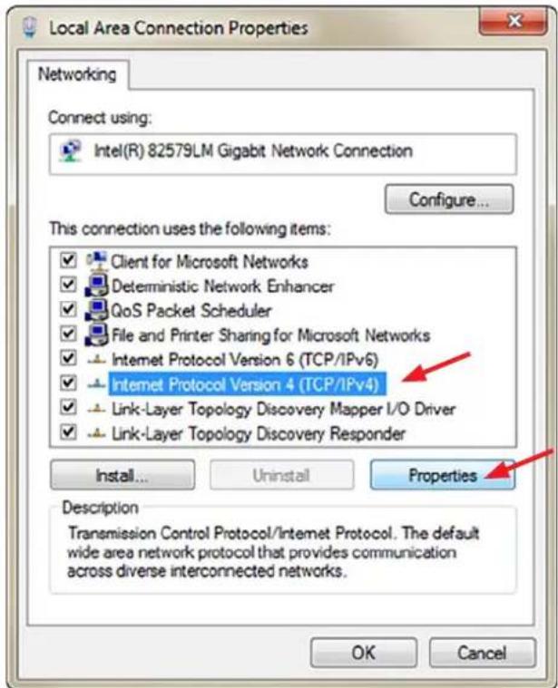
To find and change the TCP/IP address and the subnet mask on a computer running Windows:
- Go to Control Panel / Network Connections / Internet Protocol (TCP/IP).
- Set the TCP/IP address.
- Set the Subnet mask.
text_image
Local Area Connection Properties Networking Connect using: Intel(R) 82579LM Gigabit Network Connection Configure... This connection uses the following items: ✓ Client for Microsoft Networks ✓ Deterministic Network Enhancer ✓ QoS Packet Scheduler ✓ File and Printer Sharing for Microsoft Networks ✓ Internet Protocol Version 6 (TCP/IPv6) ✓ Internet Protocol Version 4 (TCP/IPv4) ✓ Link-Layer Topology Discovery Mapper I/O Driver ✓ Link-Layer Topology Discovery Responder Install... Uninstall Properties Description Transmission Control Protocol/Internet Protocol. The default wide area network protocol that provides communication across diverse interconnected networks. OK Cancel
text_image
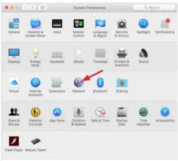
Internet Protocol Version 4 (TCP/IPv4) Properties General You can get IP settings assigned automatically if your network supports this capability. Otherwise, you need to ask your network administrator for the appropriate IP settings. Obtain an IP address automatically Use the following IP address: IP address: . . . Subnet mask: . . . Default gateway: . . . Obtain DNS server address automatically Use the following DNS server addresses: Preferred DNS server: . . . Alternate DNS server: . . . Validate settings upon exit Advanced... OK CancelTo find and change the TCP/IP address and the subnet mask on a computer running OS X:
• Go to System Preferences/ Network.
- Select "Ethernet".
• Under "Configure IPv4", select "Manually".
- Set the TCP/IP address.
- Set the Subnet mask.
text_image
System Preferences General Desktop & Screen Server Dock Mission Control Language & Region Security & Privacy Spotlight Notifications Displays Energy Server Keyboard Mouse Trackpad Printers & Scanners Sound iCloud Internet Accounts Extensions Network Bluetooth Sharing Users & Groups Parental Controls App Store Dictation & Speech Date & Time Startup Disk Time Machine Accessibility Flash Player Wacom Tablet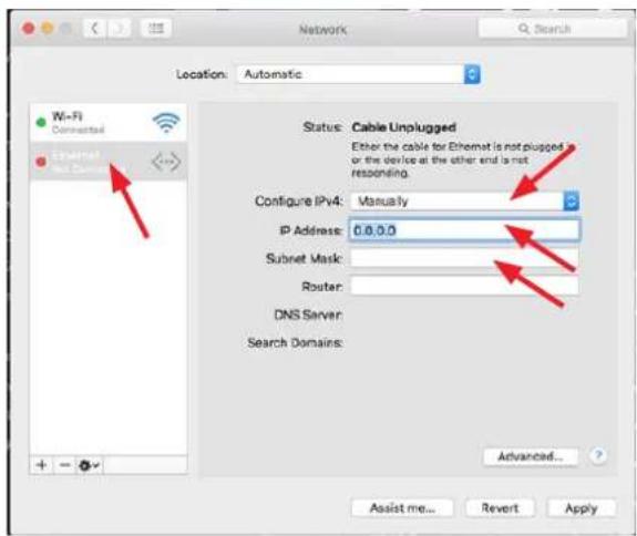
text_image
Network Location: Automatic Wi-Fi Connective Ethernet Net Server Status: Cable Unplugged Either the cable for Ethernet is not plugged in or the device at the other end is not responding. Configure IPv4: Manually IP Address: 0.0.0.0 Subset Mask: Router: DNS Server: Search Domains: Advanced... Assist me... Revert ApplyFor further information, please refer to your operating system's integrated help system.
5.1.2 Changing the subnet mask and TCP/IP address of a Reverb TwentyFour (where required)
To change the subnet mask and TCP/IP address of a Reverb TwentyFour, you need to access it using a computer running the TC Icon software.
In case there is an IP address conflict that keeps you from accessing Reverb TwentyFour in the first place, you will need to change your computer's IP first as described in the previous section.
• Launch the TC Icon software on your computer.
- Select the particular Reverb TwentyFour you want to access.
- Click on the Frame tab.
- Select the System page.
- Select the Setup subpage.
- Select Net.

text_image
TC icon Reverb TwentyFour Library Frame E1 E2 E3 Routing Status Version E1-3 VO Net System Setup Update Remote Network Identification Reverb TwentyFour Address 192.168.1.92 Latent Name 255.255.255.0 Gateway 0.0.0.0 Retiree DeviceTo change the IP address of a Reverb TwentyFour:
- Select the IP address parameter on the Net page shown above.
- Enter the new IP address.
- Confirm by clicking Enter.
To change the subnet mask:
- Select the IP Subnet Mask parameter on the Net page shown above.
• Enter the new subnet mask.
• Confirm by clicking Enter.
Resetting the IP address
You may need to reset the IP address of the Reverb TwentyFour. This procedure is done using the front panel RESET button, as described in the section "Reset button" on page 9.
If the serial number of a particular Reverb TwentyFour ends with "00", the default IP address for this device will be 192.168.1.100, as "00" is not a valid IP number in all networks.
There is a small risk that two Reverb TwentyFours (or other TC signal processors) on a network have the same last two digits in the serial number and thus will result it a conflict after a reset. To resolve this issue, reset one Reverb TwentyFour first and change its IP address before connecting the second Reverb TwentyFour.
EN
6. Quick Setup
This guide applies for a simple setup as illustrated below.
Requirements for this setup are:
• A Reverb TwentyFour.
• A CAT5 Ethernet cable.
- A computer equipped with an Ethernet adapter, running Microsoft Windows or Mac OS X and the latest version of TC Icon software.
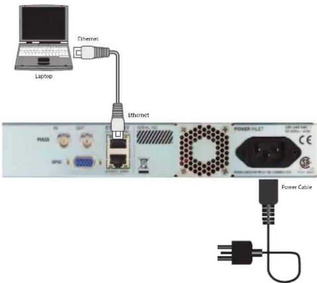
text_image
Laptop Ethernet Ethernet MADI GPO POWER FILET Power CableProcedure:
- Unpack the Reverb TwentyFour and install it in a stable, dry, and well-ventilated space.
- Connect the Reverb TwentyFour and your computer using an Ethernet cable.
• Power up your computer and the Reverb TwentyFour. - If you have not already done so, download and install the latest version of the TC Icon software editor onto your computer. (See page 5 for details)
• Launch the TC Icon software on your computer.
The following screen will appear:
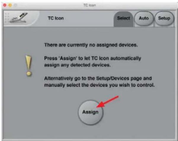
text_image
TC Icon Select Auto Setup There are currently no assigned devices. Press 'Assign' to let TC icon automatically assign any detected devices. Alternatively go to the Setup/Devices page and manually select the devices you wish to control. Assign- Click "Assign". The network is scanned, and all connected and operational devices will be listed on the next screen:
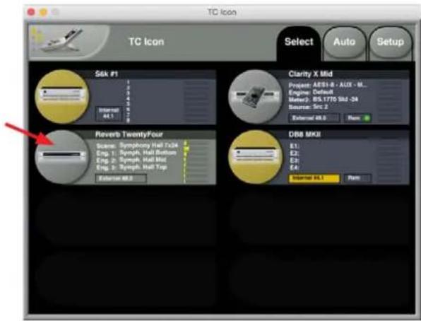
text_image
TC Icon Select Auto Setup S6k P1 Clarity X Mid Project: AESI-8 - AUS - M_ Engine: Caduah Letter: 85.1770 Std -24 Source: Src 2 External: 48.0 Rare Reverb TwentyFour Scene: Symphony Hall Tab4 Eng. 1: Symphony Hall Tab4 Eng. 2: Symphony Hall Tab4 Eng. 3: Symphony Hall Tab4 External: 48.0 Rare DB8 MKII E1: E2: E3: E4: Internal: 48.1 Rare• Select the device you wish to access.
- To have TC Icon detect more devices and assign them to one of up to eight slots, see "Assigning devices to the available slots" on page 26.
- If you cannot access the Reverb TwentyFour, please refer to "Networking basics and troubleshooting" on page 12.
Operating multiple computers and/or TC Icon devices in one network
In a more complex setup with multiple TC Icon hardware remote controls and/or several networked computers running TC Icon software, each of these TC Icon units and computers can be used to connect to TC HD devices (System 6000 MKII, Reverb TwentyFour, Loudness Pilot, UpCon) on this network.
If your setup contains multiple TC HD devices, you should name these devices unambiguously so you don't accidentally edit the settings of the wrong device.
Scanning / rescanning a network for devices
The scenario described above covers the first time you boot up your system or when no connected units are assigned.
You should scan the network again when you do any of the following:
• You make changes to your setup.
• When devices are powered up or down, or.
• If there are connection errors, these may not be detected immediately.
To scan a network for devices:
• In the TC Icon software, go to Setup/ Devices.
- Click the Detect button.
For further information, see "Devices page" on page 26.
That's it – you are now ready to configure and operate your Reverb TwentyFour.
7. Basic operation with the TC Icon software
Introduction
This section of the manual is a general introduction to operating the Reverb TwentyFour using the TC Icon software.
In the following chapters we assume that you have successfully connected the Reverb TwentyFour unit and your computer directly, or as part of a network as described in "Quick Setup" on the previous page.
Several Reverb TwentyFour and other TC signal processors (e.g. Clarity-X, DB4/DB8 MKII), and computers running the TC Icon software can be connected and operated at the same time as part of a standard Local Area Network (LAN). The TC Icon software is used to detect, configure and operate devices from your computer.
If you encounter communication errors or cannot detect or operate a device properly, please refer to "Networking basics and troubleshooting" on page 12.
The following sections of this manual assume that you are operating a basic system with only one Reverb TwentyFour connected.
7.1 TC Icon interface
The TC Icon software interface has been optimized for use in real-time situations in film and post production environments (which usually are very different from standard desktop computing tasks and environments). Accordingly, the on-screen buttons are very prominent and clearly-labelled to ensure proper operation even in stressful situations. In addition, important parameters can be assigned to on-screen faders, allowing for precise control and immediate visual feedback.
The interface can be customized. Customizable parameters include the position of the faders and the user interface colors. For more information, please refer to the chapters "UI page" on page 27" and "Color page" on page 28 of this manual.
7.1.1 Tabs versus pages
- Use the tab buttons on the upper edge of the TC Icon window to select a primary group of functions.
- Use the page buttons on the left edge of the TC Icon window to select specific pages within each tab.
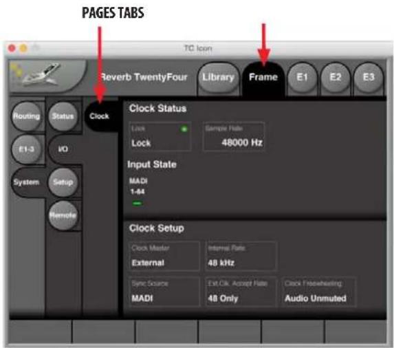
text_image
PAGES TABS Reverb TwentyFour Library Frame E1 E2 E3 TC Icon Routing Status Clock E1-3 I/O System Setup Remote Clock Status Lock Sample Rate Lock 48000 Hz Input State MADI 1-44 Clock Setup Clock Master Internal Rate External 48 kHz Sync Source Exit CLK Accept Rate MADI 48 Only Clock Presheathing Audio Unmuted7.1.2 TC Icon modes: Base and Device operation
The TC Icon software has two operation modes: Base and Device operation.
Use Base operation mode to select devices and configure the network and the TC Icon software itself.
- In Base mode, you will see the Select, Auto and Setup tabs on the upper edge of the initial TC Icon window that appears before you select a TC device. Most Base mode functions are described in the chapter "TC Icon Setup" on page 26.
text_image
TC Icon Select Auto Setup S6k #1 Clarity X Mid Project: AESI-8 - AUX - M... Engine: Default Model: B/S 1779 Shd-24 Source: Src 2 External: A4.0 Reverb TwentyFour Scope: Symphony Hall Tx24 Eng. 1: Synph. Hall Bottom Eng. 2: Synph. Hall Top Eng. 3: Synph. Hall Top External: A4.0 DBB MKII E1: E2: E3: E4: Internal: A4.1 PortUse Device operation mode to operate the currently selected device.
- In Device Mode, you will see the specific tabs for operating the currently selected TC device.

text_image
TC Icon Reverb TwentyFour Library Frame E1 E2 E3 Routing Status Fension E1-3 PO Net System Setup Update Remote Network Identification Network identification Reverb TwentyFourAugments
Augments Block
192.168.1.92 255.255.255.0Customing
0.0.0.0 Roboof DeviceSwitching between Base and Device operation modes:
To switch between Base and Device operation modes, click the TC Icon symbol in the upper left corner of the window.

natural_image
Illustration of a handheld electronic device with a screen and buttons, no visible text or symbols.
7.1.3 Faders
The TC Icon software has six large on-screen faders along the bottom edge of the interface. They have several features that will help you operate your Reverb TwentyFour efficiently:

natural_image
Six identical vertical cylindrical objects with circular ends, arranged horizontally (no text or symbols visible)• There are six on-screen faders.
- You can change the position of the faders or hide them completely – see "UI page" on page 27.
- The name of the parameter that a fader is currently assigned to is displayed above the fader.
- When no label is shown above a fader, that fader is currently not assigned to a parameter.
- Fader assignments and values will always reflect the last Engine E1, E2, E3, that you have accessed.
Using Faders for fine adjustments
When a parameter is assigned to a fader, you can choose between Normal and Fine adjustment mode.
- In Normal Adjustment mode, the fader range will cover the full parameter range – e.g. -18 dB to 18 dB for the Center Trim parameter.
- In Fine Adjustment mode, the fader range will be smaller, allowing you to fine-tune around the current value – e.g. in 0.1 dB steps for a level parameter.
To switch a fader from Normal Adjustment mode to Fine Adjustment mode or back, click the label above that fader. Fine Adjust mode will be indicated by two triangles in the label field.
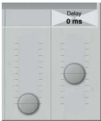
text_image
Delay 0 msFader Groups
The Reverb TwentyFour uses many parameters on several pages. For efficient operation, the most important parameters can be assigned to the on-screen faders in Fader Groups. Fader Groups allow you to access the most important features immediately, no matter what particular page is currently being displayed.
You can access predefined Fader Groups that cover typical applications, and you can define a User Fader Group with your own assignment for each fader.
You can select and customize Fader Groups per Engine – meaning that you can use one group of fader assignments for Engine 1, and others for Engine 2 and 3.
To select a Fader Group
- Select the tab of an Engine E1, E2, or E3 (on the top edge of the TC Icon software window).
- Use the arrow buttons on the Fader Group selector (at the lower left) to select the desired Fader Group. The name of the currently selected Engine and Fader Group are displayed on the Fader Group selector. E.g., "E1 Group 1" means that you have selected the predefined Fader Group 1 for Engine 1.

text_image
TC Icon Reverb TwentyFour Library Frame E1 E2 E3 Edit Main Name Symph. Hall Bottom Equation Reverb8 Levels In Level 0.0 dB Dry Light Off Power Control 50% Cut Level Grp 1 0.0 dB Multi Grp 1 Cut Level Grp 2 0.0 dB Multi Grp 2 Pre Delay Pre Delay Grp 1 0 ms Zero Grp 1 Pre Delay Grp 2 0 ms Zero Grp 2 Output 1 2 3 4 5 6 7 8 E1 Group User Pre Delay Grp 1 0 ms Pre Delay Grp 2 0 ms Decay 2.4 s Lo Decay 1.00 Hi Decay 1.00 Hi Cut 1.95 kHzTo set up the User Fader Group
• Select the tab of an Engine as shown above.
- Use the arrow buttons on the Fader Group selector to select the "User" Fader Group.
- Click the circular "Fader Asgn" button (on the left edge of the TC Icon software window).
- Click the label of a fader that you want to assign to a parameter.
- Click the name of the parameter that you want to assign to the previously selected fader.
- Repeat the last two steps until you have made all desired assignments.
- Click the circular "Fader Asgn" button again.
Assigning Fader 6 on the fly
Even when using one of the pre-defined Fader Groups for an Engine, you can always assign the sixth Fader to whatever parameter you want to control in a given situation. Like all other Fader-related settings, this is an Engine-specific setting: You can assign Fader 6 to one parameter when Engine 1 is selected and to another parameter when Engine 2 is selected.
To assign a parameter to Fader 6:
- To assign a parameter to the fader 6, simply click on a parameter field. That parameter will immediately be assigned to the sixth fader. If that parameter is also assigned to one of the other faders, you can now use both faders to control that parameter.
On-screen keyboard
Reverb TwentyFour allows you to store and rename presets, assign labels to inputs and outputs, and perform other functions where text input is required. When you access any of these functions, an on-screen keyboard will be displayed.

text_image
A/85 HD Universal Esc Back Delete 1 2 3 4 5 6 7 8 9 0 1 Q W E R T Y U I O P { } Shift A S D F G H J K L : * { Z X C V B N M < > ? - UT: Group 7 UIt: Group 8 EnterWhile they keyboard is being displayed, you can either click the letters shown on-screen or use your computer's keyboard for character input. When you are done, click the large Enter button or press your computer keyboard's Enter key.
7.2 System/ Status page
Please note that the LEDs on the Reverb TwentyFour front panel will display basic status information as long as the device is powered – see "Controls and Connectors" on page 9.
To display additional status information about the Reverb TwentyFour, go to Frame/System/Status in the TC Icon software.
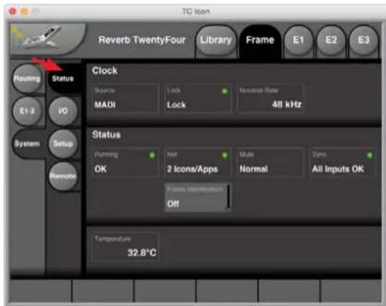
text_image
TC Icon Reverb TwentyFour Library Frame E1 E2 E3 Routing Status Clock Source Lock Notional Rate MADI Lock 48 kHz E1-3 IO System Setup Remote Status Running OK Test 2 Icons/Apps Normal Canc All Inputs OK Frame Identification Off Temperature 32.8°CThis page will display the following status information:
Clock section
- SOURCE indicator – Indicates the source of the clock signal that the Reverb TwentyFour is currently following.
- LOCK indicator – Indicates if synchronization has been achieved. If no synchronization has been achieved, a red LED will be shown in this field.
- NOMINAL RATE indicator – Shows the detected sample rate of the signal Reverb TwentyFour is synced to (48 KHz).
Status section
The indicators in this section follow the same status as the front panel LEDs described on page 9. Please refer to that page as it shows tables of the various LED color codes and their meaning.
- RUNNING indicator – Displays the current state of the Reverb TwentyFour power supply. A power supply failure may be indicated as described under "Power LED" on page 9.
- NET indicator – Displays the number of TC Icons hardware devices or the number of computers running TC Icon software, that have been detected on the network.
- MUTE – Indicates if the Reverb TwentyFour is running in Bypassed mode or Normal mode.
- SYNC indicator – The LED indicates if synchronization to the signal source has been achieved.
- FRAME IDENTIFICATION – If you are operating multiple Reverb TwentyFour units, you may need to identify one specific unit quickly. To do so, select the Frame Identification parameter to have that Frame identify itself with a blinking front panel NET LED. The color/color combination is selected by moving the small slider at the right of the Frame Identification box: "Green/Off", "Yellow/Off", "Red/Off", "Green/ Yellow", Green/Red", "Yellow/Red" or "Off".
- Temperature indicator – Shows the current internal temperature of the Reverb TwentyFour in degrees Celsius.
EN
7.3 System/ I/O
Go to Frame/System/ I/O.
Use this page to:
• Display clock status.
• Display input state.
• View the clock settings.
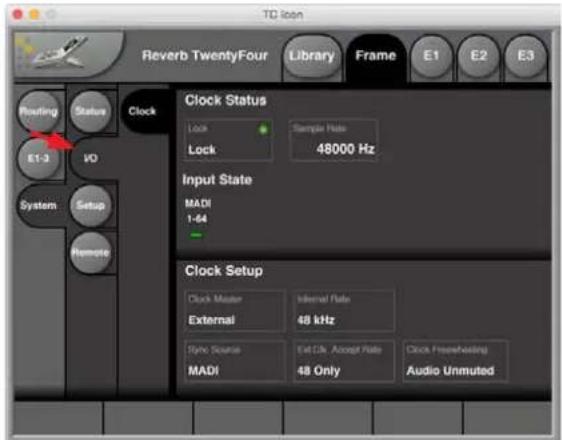
text_image
Reverb TwentyFour Library Frame E1 E2 E3 Refring Status Clock E1-3 VO System Setup Remote Clock Status Lock Sample Rate 48000 Hz Input State MADI 1-64 Clock Setup Clock Master Internal Rate External 48 kHz Style Source Ext CI, Accept Rate MADI 48 Only Clock Free/Healing Audio UnmutedClock Status
- LOCK indicator – The Lock status field shows the top-level lock status of an incoming MADI stream.
- When Reverb TwentyFour is locked to an acceptable MADI stream, "Lock" is shown.
- When no acceptable MADI stream is available, "No Lock" and a red LED will be shown in this field.
- Sample Rate indicator – When the Reverb TwentyFour is locking to an incoming MADI stream, the sample rate in Hz will be shown. If the Reverb TwentyFour is not locking, the indicator field will read "N/A".
Input State
- MADI 1-64 – The LED below this text will indicate green when MADI input is present.
Clock Setup
- Clock Master – The Reverb TwentyFour can only sync to the external MADI input.
- Internal Rate – If the MADI input is lost, it will revert to the internal clock at 48 KHz = "Freewheeling".
- Sync Source – The Reverb TwentyFour can only sync to MADI.
- Ext.Clk Accept Rate – The Reverb TwentyFour can only sync at 48 kHz.
- Clock Freewheeling – If the unit is freewheeling, then the audio output is unmuted.
74 System/ Setup/ Version
Go to Frame/System/Setup/Version.
Use this page to:
• Show the unit's unique factory serial number.
• Show the TC Icon software version number.
• Show the unit's SW version number (i.e. the firmware version).
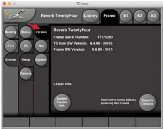
text_image
TC Icon Reverb TwentyFour Library Frame E1 E2 E3 Routing Status Version E1-3 HO Net System Setup Update Remote Reverb TwentyFour Frame Serial Number: 17175290 TC Icon SW Version: 8.4.00 - 30456 Frame SW Version: 0.6.00 - 3415 Latest Info: Update Version Info Reset Unit to Factory Defaults. preserving User Presets Reset to DefaultsThis page also has 2 buttons in the lower section as follows:
- Update Version Information – press the circular button in the lower left, to update the information, if for example, you have updated the TC Icon software or the Reverb TwentyFour's firmware.
- Reset to Defaults – press the circular button in the lower right to reset the Reverb TwentyFour to its factory default settings. Any user presets will be saved and not lost.
7.5 System/ Setup/ Net
Go to Frame/System/Setup/Net
Use this page to:
• Show the network parameters and network name of the device.
- Reboot the device.
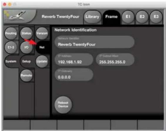
text_image
TC Icon Reverb TwentyFour Library Frame E1 E2 E3 Routing Status Version E1-3 IO Net System Setup Update Remote Network Identification Reverb TwentyFour * Address * Subject Name 192.168.1.92 255.255.255.0 * Address 0.0.0.0 Subboot DeviceThis page shows details of the various network parameters. These can be altered if required, by clicking on the numbers and entering new numbers.
• Network Identifier – this shows the device name, the Reverb TwentyFour.
- IP Address – The TCP/IP address of each device connected to a network has to be unique. An IP address consists of four decimal numbers (ranging from 0 to 255) separated by dots, e.g. 192.168.1.1 The first three numbers (e.g. "192.168.1") must be the same for each unit – but the remaining number has to be unique in the subnet, i.e., no two units in the subnet can have the same last number. The default IP address of each Reverb TwentyFour is 192.168.1.[nn], where [nn] is identical to the last two digits in the Reverb TwentyFour's serial number (shown on a label on the rear panel of the device, or in the system/setup/version page). This way, multiple Reverb TwentyFours can be setup directly out of the box without having to change their IP numbers.
- IP Subnet Mask – The subnet mask is a number that defines a "group" of computers (or other devices) connected to a network. All units in this group must have the same subnet mask. The default subnet mask of each Reverb TwentyFour is 255.255.255.0.
• IP Gateway – The default value is 0.0.0.0 and is not usually changed.
- Reboot Device – press this circular button to reboot the Reverb TwentyFour on the network. This should be done if you have made any changes to the settings above, or any physical changes to the external network or connections.
7.6 System/ Setup/ Update
Go to Frame/System/Setup/Update.
Use this page to:
• Enter the file location of the latest downloaded firmware file.
• Find the downloaded firmware file.
• Install the new firmware.

text_image
TC Icon Reverb TwentyFour Library Frame E1 E2 E3 Routing Status Version E1-3 I/O Net System Setup Update Remote Software Update Overpass Software Update Frame /Users/IcelectronicStudio/Desktop/ ReverbTwentyFour_0_4_00-3407 Update SW File Info Get SyslogTo update the firmware, please proceed as follows:
- Please go to www.tcelectronic.com and locate the Reverb TwentyFour section. Alternatively, you can visit the support\software section and locate the available software downloads for the Reverb TwentyFour unit.
- Download the Reverb TwentyFour firmware if it is newer than the version shown in the System/Setup/Version page.
Firmware
+ Show version history

Released: Tuesday May 29, 2017
+ Show previous versions
TC Icon Software
+ Show version history

Released: Tuesday May 29, 2017

Released: Tuesday May 29, 2017
- If the file is zipped, please unzip it and make a note of its file location on your computer.
- In the "Common Software Update Folder" area of the System/Setup/Update page above, enter the folder where you stored the downloaded firmware file, and press enter. The available file should now appear in the area below.
- Check that the filename is correct, and then press the circular "Update SW" button at the right. Be careful, as there may be more than one firmware file shown, so make sure you get the latest version.
- The firmware should now be downloaded onto the Reverb TwentyFour, and a confirmation will be shown on-screen when this is completed.
EN
7.7 System/ Remote
Go to Frame/System/Remote.
This Remote page allows you to access remote features of the Reverb TwentyFour through an external interface. For example, an external switch box can be made so that different scene presets can be chosen remotely. More details of this feature can be found on page 41.
Use this page to:
- GPI – setup, choose, and enable different scene presets for remote recall.

text_image
TC Icon Reverb TwentyFour Library Frame E1 E2 E3 Routing Status GPI E1-3 PO Call System Setup GPO Remote GPI 1 - Scene Recall 4 Presets Enable Service Block Status User 3 (1-4) 1 GPI 2 - Processing Control GPI 3 - Resetting GPI 4 - Logging Function 4 Presets- Cal – calibrate the operation of the external equipment.

text_image
TC Icon Reverb TwentyFour Library Frame E1 E2 E3 Routing Status GPI E1-3 VO Cal System Setup GPO Remote GPI Current GPI 1 Voltage 1.000 Vs GPI 2 Voltage 1.000 Vs GPI 3 Voltage 1.000 Vs GPI 4 Voltage 1.000 Vs GPI Limits GPI 1 Hi Threshold 1.000 Vs GPI 2 Hi Threshold 1.000 Vs GPI 3 Hi Threshold 1.000 Vs GPI 4 Hi Threshold 1.000 Vs GPI 1 Lo Threshold 0.000 Vs GPI 2 Lo Threshold 0.000 Vs GPI 3 Lo Threshold 0.000 Vs GPI 4 Lo Threshold 0.000 Vs Calibrate Calibrate Calibrate Calibrate• GPO – setup operation of external LEDs.

text_image
TC Icon Reverb TwentyFour Library Frame E1 E2 E3 Routing Status GPI E1-3 I/O Call System Setup GPIO Remote Setup GPO 1 GPO 2 Sync LED Alert LED Live Time 1 Closed Open7.8 E1-3 page
Go to Frame/E1-3.
Use this page to:
- View the User group parameters for all 3 Engines. Selecting User group parameters is done from the Engine Edit pages E1, E2, E3.
- Values can be altered from this page, as well as from the 3 individual Engine Edit pages.
• Press the parameter you wish to assign to the Fader located below. - At the right of the screen is a general Wet level (Out Level) parameter that works on all 3 engines.
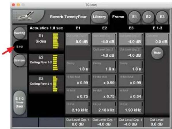
text_image
TC Icon Reverb TwentyFour Library Frame E1 E2 E3 Acoustics 1.8 sec E1 E2 E3 E 1-3 Routing E1 Sides 0.0 dB Out Level Grp. 1 -4.0 dB Out Level Grp. 2 -4.0 dB Out Level Grp. 3 -4.0 dB Mute E1-3 System E2 Ceiling Row 1-3 Energy 1.8 s Energy 1.8 s Energy 1.8 s E3 Ceiling Row 3-4 Ht Mio Mul x 0.99 Ht Mio Mul x 0.99 Ht Mio Mul x 0.99 Ht Mio Mul x 0.75 Ht Mio Mul x 0.75 Ht Mio Mul x 0.64 Ht Cut 2.18 kHz Ht Cut 2.18 kHz Ht Cut 1.90 kHz E 1-3 Group User Out Level Grp. 1 0.0 dB Out Level Grp. 1 -4.0 dB Out Level Grp. 1 -4.0 dB Out Level 0.0 dBBypass Mode
- There is also an overall Mute button, which mutes the wet part only. The Reverb TwentyFour is then in Bypass mode, and the BYPASS LED will light on the front panel.
8. Using the Library
Recalling, storing and deleting settings, scenes, routings, engines
To use the Reverb TwentyFour effectively, you should make all required settings as described in this manual and then store them, so they can later be recalled. You may also want to name the settings you store, and delete settings that are no longer required. All these features are described in this Library section.
You first need to understand the hierarchical structure of your Reverb TwentyFour of Scenes, Engines, and Routings:
Scenes
A Scene is the most extensive selection you can make when recalling, storing or deleting settings. A Scene includes:
- All settings for all 3 Engines.
• Signal routings to and from these Engines.
• Recalling a Scene is equivalent to a "total recall".
• All the settings that make up a Scene are called a Scene preset.
Recalling (loading), storing (saving) and deleting Scene Presets is covered in this Library chapter.
Engines
Instead of recalling or storing a full Scene as described in the previous section, you may want to edit, store or recall the settings for one particular Engine.
All the settings for one particular Engine are called an Engine preset.
Recalling (loading), storing (saving) and deleting Engine Presets is covered in this Library chapter.
Routings
All the settings that define how signals are routed to and from the Engines are called a Routing preset.
Recalling (loading), storing (saving) and deleting Routing Presets is covered in this Library chapter.
The Library concept
The Library gives you access to all settings of all parameters of the currently selected Reverb TwentyFour.
The highest organizational level of the Library is a Bank. A Bank will hold:
- Scene presets.
- Routing presets.
• Engine presets.
Factory presets vs. user presets
When recalling presets, you will see that there are two categories of presets: Factory presets and User presets.
- Factory presets can only be recalled, but not overwritten or deleted. If you change a Factory preset and you want to keep it, you have to store it as a User preset.
- User presets can be recalled, edited and stored, thereby overwriting the previous version.
8.1 Library - Recall
Use the Library Recall page of the TC Icon software to recall (load) previously stored settings into the memory of the currently selected device.
All colored buttons and selected items on the Recall page are colored in green.
To access the Library Recall page:
- If it isn't already, select the device you want to control using the Select page – see "TC Icon modes: Base and Device operation" on page 15.
- Select the "Library" tab.
- Select the "Recall" page.
- Select the subpage for the setting type you want to access:
- Scene – to recall a Scene preset.
- Routing – to recall a Routing preset.
- E(ngine) 1, 2, or 3 – to recall an Engine preset and use it for the currently selected Engine.
- Select between Factory and User preset groups by clicking the Factory or User button.

text_image
TC Icon Reverb TwentyFour Library Frame E1 E2 E3 Recall Scene Preset Acoustics 1.0 sec Store Routing Delete E1 F1: Unwrap 24 Channels 1 Acoustics 0.6 sec E2 F2: Unwrap 16 Channels 2 Acoustics 0.8 sec E3 F3: Film 24 Ch. In/Out 3 Acoustics 1.2 sec F4: Film 3 x Surround 4 Acoustics 1.8 sec F5: Acoustics, RT60 5 Acoustics 2.2 sec E3 6 Acoustics 2.7 sec Acoustics 0.6 sec 2x24, Side columns, Ceiling rows 1-4 Acoustics 0.8 sec 2x24, Side columns, Ceiling rows 1-4 Acoustics 1.2 sec 2x24, Side columns, Ceiling rows 1-4 Acoustics 1.8 sec 2x24, Side columns, Ceiling rows 1-4 Acoustics 2.2 sec 2x24, Side columns, Ceiling rows 1-4 Acoustics 2.7 sec 2x24, Side columns, Ceiling rows 1-4There are up to 8 Factory and 8 User preset groups, with each group holding up to 8 presets.
- Select a preset you want to use.
- Click the large "Recall (Scene/ Route/ Engine) Preset" button in the upper right corner to recall (activate) the selected preset.
The selected preset will be recalled.
Preset information
For some presets, additional information is stored as part of the preset. When you select such a preset, an inverted "Info" tag will appear at the bottom of the large Preset Recall button. Keep an eye out for it.

text_image
Recall Scene Preset Current: Symphony Hall 7x24 Symphony Hall 1x24 info- Click the Info tag to display additional information about this preset in a modal dialog.
• Click the OK button to close the dialog.
EN
Library/Recall/Scene Presets

text_image
TC Loan Reverb TwentyFour Library Frame E1 E2 E3 Recall Scene Preset Acoustics 1.8 sec Acoustics 0.6 sec Store Routing F1: Unwrap 24 Channels F2: Unwrap 16 Channels F3: Film 24 Ch, In/Out F4: Film 3 x Surround F5: Acoustics, RT60 1 Acoustics 0.6 sec 2x24, Slide columna, Ceiling rows 1-4 2 Acoustics 0.8 sec 2x24, Slide columna, Ceiling rows 1-4 3 Acoustics 1.2 sec 2x24, Slide columna, Ceiling rows 1-4 4 Acoustics 1.8 sec 2x24, Slide columna, Ceiling rows 1-4 5 Acoustics 2.2 sec 2x24, Slide columna, Ceiling rows 1-4 6 Acoustics 2.7 sec 2x24, Slide columna, Ceiling rows 1-4Library/Recall/E2 (Engine 2) Presets
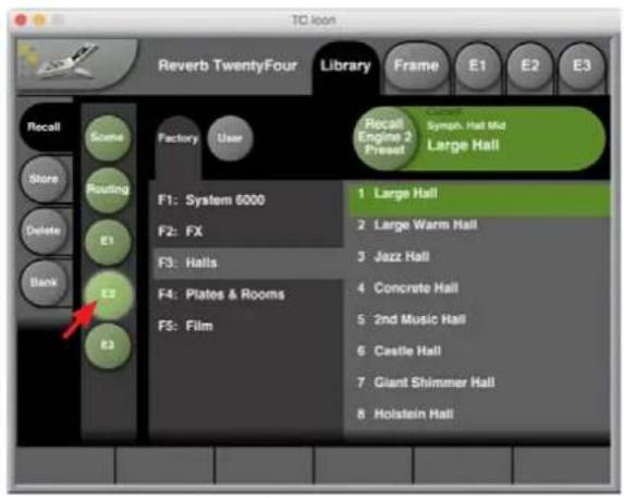
text_image
Reverb TwentyFour Library Frame E1 E2 E3 Recall Scene Store Routing Delete Bank Factory User F1: System 6000 F2: FX F3: Halls F4: Plates & Rooms F5: Film Recall Engine 2 Press Symph. Hall Mid Large Hall Large Hall Large Warm Hall Jazz Hall Concrete Hall 2nd Music Hall Castle Hall Giant Shimmer Hall Holstein HallLibrary/Recall/Routing Presets

text_image
TC icon Reverb TwentyFour Library Frame E1 E2 E3 Recall Some Factory User Store Routing Delete E1 F1: Mono, Stereo, 24 E2 E3 Recall Routing Preset Umap Tx34 SMPTE 1 in, 24 out F1: Mono, Stereo, 24 F2: 5.1 surround F3: 7.1 surround 1 1 in, 24 out Ch 1 in, 1-24 out, SMPTE 7.1 2 2 in, 24 out Ch 1-2 in, 1-24 out, SMPTE 7.1 3 24 in, 24 out Ch 1-24 out, SMPTE 7.1 4 Empty Routing Remove all wind readingsLibrary/Recall/E3 (Engine 3) Presets

text_image
TC Icon Reverb TwentyFour Library Frame E1 E2 E3 Recall Scene Factory User Recall Engine 3 Preset Symph. Hall Top Kitchen Store Routing F1 System 6000 1 Kitchen Delete R1 F2 FX 2 Aula Bank R2 F3 Halls 3 Conference Room A3 F4 Plates & Rooms 4 Parking Garage F5 Film 5 Living Room Warm Dialog Empty Factory Old TheatreLibrary/Recall/E1 (Engine 1) Presets
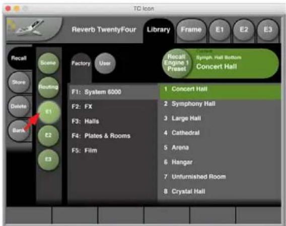
text_image
Reverb TwentyFour Library Recall Engine 1 Preset Symph. Hall Bottom Concert Hall F1: System 6000 F2: FX F3: Halls F4: Plates & Rooms F5: Film 1 Concert Hall 2 Symphony Hall 3 Large Hall 4 Cathedral 5 Arena 6 Hangar 7 Unfurnished Room 8 Crystal Hall8.2 Library - Store
Use the Library Store page of the TC Icon software to store (save) settings to a memory bank. You can only store settings as User presets. Factory presets cannot be overwritten.
All colored buttons and selected items on the Store page are colored in red.
To access the Library Store page:
- Select the "Library" tab.
-
Select the "Store" page.
• Select the subpage for the setting type you want to store: -
Scene – to store all settings (including Routing and all algorithm settings) as a Scene.
- Routing – to store the current Routing.
- E(engine) 1, 2 or 3 – to store the settings of either Engine 1, 2, or 3 as an Engine preset.
- Select a User preset group. There are 8 User preset groups, with each group holding up to 8 presets.
- Select a preset slot in the currently selected group that you want to use.
- Click the large "Store (Scene / Route / Engine) Preset" button to store (save) your settings as a preset.
- The selected data type will be stored as a preset. You can then recall this preset – see "Library – Recall page" on page 21.
Naming Presets
All user preset types can be (re)named.
To rename a preset:
- On the Store page, select the preset that you want to rename.
- Click the circular "Name" button.
• An on-screen keyboard will be shown. - Use the on-screen keys or the physical keyboard of your computer to edit the name.
- Click the large Enter button to confirm the new name.
Please note that the preset itself is not stored when you click the Enter button! To store the preset with its new name, click the large "Store (Scene/ Route/ Engine) Preset" button.
Adding Preset Information
You can add information to presets you have created or modified. When recalling such a preset later, a small inverted "Info" tag will appear at the bottom of the large Preset Recall button, allowing you to access this additional information.
To add information to a preset:
• On the Store page, select the preset that you want to add information to.
- Click the "Info" button.
• An on-screen keyboard will be shown.
- Use the on-screen keys or the physical keyboard of your computer to enter the information.
- Click Enter to confirm.
Please note that the preset itself is not stored when you click the Enter button! To store the preset with the newly added information, click the large "Store (Scene/ Route/ Engine/) Preset" button.
Operating the unit while renaming presets
Please note that even when renaming presets or adding information as described above, the faders for the previously accessed page are still available and operational.
Library Store Scene
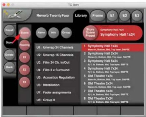
text_image
Reverb TwentyFour Library Frame E1 E2 E3 Store Scene Preset Symphony Hall 7x24 Symphony Hall 1x24 U1: Unwrap 24 Channels U2: Unwrap 16 Channels U3: Film 24 Ch. In/Out U4: Film 3 x Surround U5: Acoustics Regulation U6: Installation U7: Fader assignments U8: Group 8 1 Symphony Hall 1x24 Memo in, Bottom, Mid, Top layer, SMPTE 2 Symphony Hall 2x24 Memo in, Bottom, Mid, Top layer, SMPTE 3 Symphony Hall 5x24 N, I) In, Bottom, Mid, Top layer, SMPTE 4 Symphony Hall 7x24 N, I) In, Bottom, Mid, Top layer, SMPTE 5 Old Theatre 1x24 Memo in, Bottom, Mid, Top layer, SMPTE 6 Old Theatre 2x24 Sicero in, Bottom, Mid, Top layer, SMPTE 7 Old Theatre 5x24 N, I) In, Bottom, Mid, Top layer, SMPTE 8 Old Theatre 7x24 N, I) In, Bottom, Mid, Top layer, SMPTELibrary Store Routing
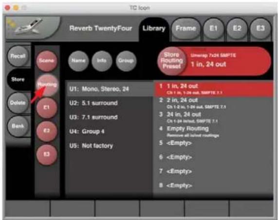
text_image
TC Icon Reverb TwentyFour Library Frame E1 E2 E3 Store Routing Preset Unimap 7x24 SMPTE 1 in, 24 out U1: Mono, Stereo, 24 U2: 5.1 surround U3: 7.1 surround U4: Group 4 U5: Not factory 1 1 in, 24 out Cn 1 in, 1-24 out, SMPTE 2.1 2 2 in, 24 out Cn 1-2 in, 1-24 out, SMPTE 7.1 3 24 in, 24 out Cn 1-24 input, SMPTE 7.1 4 Empty Routing Remove all input routings 5Library Store Engine E1
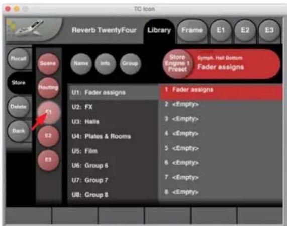
text_image
TC icon Reverb TwentyFour Library Frame E1 E2 E3 Recall Scene Name Info Group Store Engine 1 Preset Symph. Hall Bottom Fader assigns Store Routing U1: Fader assigns 1 Fader assigns U2: FX 2EN
8.3 Library – Delete
Use the Library Delete page of the TC Icon software to delete user presets from a memory bank. You can only delete user presets. Factory presets cannot be deleted.
Please note that all colored buttons and selected items on the Delete page are colored in yellow.
To access the Library Delete page:
- Select the "Library" tab.
-
Select the "Delete" page.
• Select the subpage for the setting type you want to delete: -
Scene.
-
Routing.
E(ngine) 1, 2, or 3. -
Select a User preset group. There are up to 8 User preset groups, with each group holding up to 8 presets.
- Select a preset in the currently selected group that you want to delete.
- Click the large "Delete (Scene/ Route/ Engine) Preset" button to delete the selected preset.
- You will be asked to confirm this operation before the preset is actually deleted.
Operating the unit while deleting presets
Please note that even when deleting presets, the faders for the previously accessed page are still available and operational.
Library Delete Scene
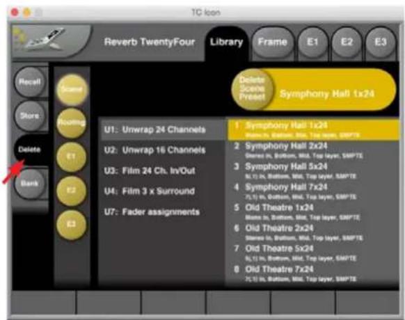
text_image
TC Icon Reverb TwentyFour Library Frame E1 E2 E3 Delete Scene Present Symphony Hall 1x24 U1: Unwrap 24 Channels U2: Unwrap 16 Channels U3: Film 24 Ch. In/Out U4: Film 3 x Surround U7: Fader assignments 1 Symphony Hall 1x24 Made in, Bottom, Mid, Top layer, SMPTE 2 Symphony Hall 2x24 Made in, Bottom, Mid, Top layer, SMPTE 3 Symphony Hall 5x24 N, I, In, Bottom, Mid, Top layer, SMPTE 4 Symphony Hall 7x24 N, I, In, Bottom, Mid, Top layer, SMPTE 5 Old Theatre 1x24 Made in, Bottom, Mid, Top layer, SMPTE 6 Old Theatre 2x24 Made in, Bottom, Mid, Top layer, SMPTE 7 Old Theatre 5x24 N, I, In, Bottom, Mid, Top layer, SMPTE 8 Old Theatre 7x24 N, I, In, Bottom, Mid, Top layer, SMPTE8.4 Library - Bank page
Use the Library Bank page of the TC Icon software to copy Scene / Routing/Engine / Presets from one location to another.
You can copy Presets to and from Banks and files.
Files can be transferred to other computers, allowing you to easily reuse presets.
To access the Library Bank page:
- If it isn't already selected, select the device you want to control using the Select page – see "TC Icon modes: Base and Device operation" on page 15.
- Select the "Library" tab.
- Select the "Bank" page.
-
Select the subpage for the setting type you want to copy:
-
Scene.
- Routing.
• E(ngine) 1, 2 or 3.
To copy from a Bank to a file on disk.
- Select "From Bank" in the first column. The second column will switch to "To File" accordingly.
- Specify the folder where the file should be written in the "File Folder" field.
• If you want to overwrite an existing file, select it in the right column. - If you select "New file" instead, you will be prompted to specify the file name.
- Click the "Copy Bank" button.
To copy from a file on disk to a Bank.
- Select "From File" in the first column. The second column will switch to "To Bank" accordingly.
- Specify the folder from where the file should be read in the "File Folder" field.
- Click the "Copy Bank" button.
Library Bank Scene
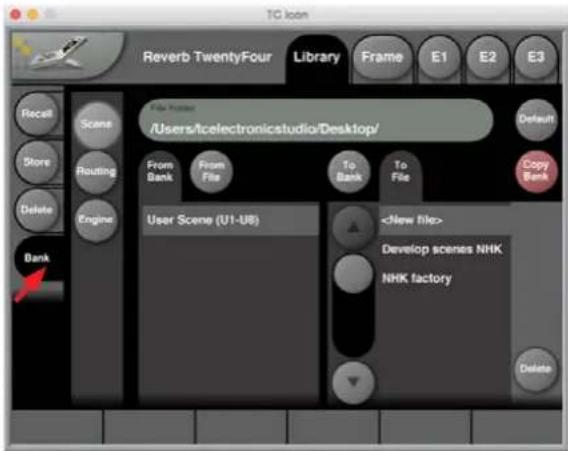
text_image
Reverb TwentyFour Library Frames E1 E2 E3 Recall Scans Store Routing Delete Engine Bank File Manager /Users/Icelectronicstudio/Desktop/ From Bank From File To Bank To File User Scene (U1-UB)Library Bank Routing
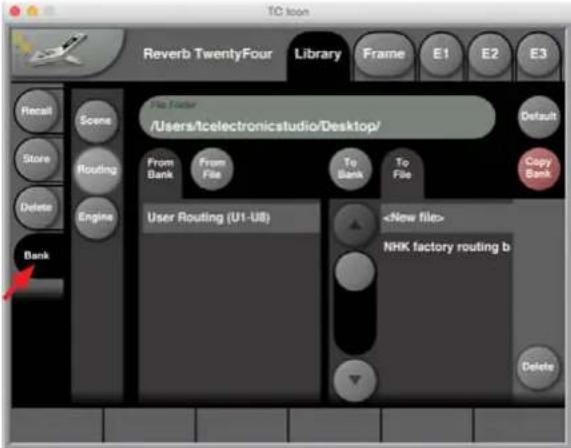
text_image
Reverb TwentyFour Library Frame E1 E2 E3 File Fifier /Users/Icelectronicstudio/Desktop/ From Bank From File To Bank To File User Routing (U1-U8)Library Bank Engine
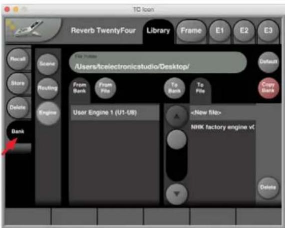
text_image
Reverb TwentyFour Library Frame E1 E2 E3 Recall Scene Store Routing Delete Engine Bank File Moves /Users/Icelectronicstudio/Desktop/ From Bank From File To Bank To File User Engine 1 (U1-U8)EN
9. TC Icon Setup
This chapter covers screens and parameters of the TC Icon software not directly related to the day-to-day operation of your Reverb TwentyFour.
Accessing the Icon Setup pages.
- Switch the TC Icon software to Base mode by clicking the Icon symbol in the upper left corner of the window.

text_image
tc electron TC Icon Select Auto SetupIn Base Mode, you will see the Select, Auto and Setup tabs on the upper edge of the TC Icon window.
- Select the Setup tab.
- Select one of the pages described below: Info, Devices, Security, UI, and Color.
9.1 Info page
On this page, the version number of the currently installed TC Icon software is displayed. To update the TC Icon software, please refer to the "TC Icon software installation" on page 5 of this manual.
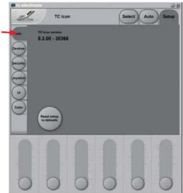
text_image
TC electronic TC icon Select Auto Setup Auto TC icon version 8.3.00 - 30366 Reset setup to defaults9.2 Devices page

text_image
TC Icon Select Detect Reverb TwentyFour Detected 1 device TC Icon can control up to eight devices which can be arranged in slots and accessed through the main select page. Select a free slot for this device: 1 5 Occupied 6 Occupied 7 4 8Use this page to detect, control and assign the devices in your local network.
- Detect button – Click the "Detect" button to scan the network for connected devices. All detected devices will appear in the list.
- If you encounter problems when detecting connected devices, please refer to "Networking basics and troubleshooting" on page 12.
Assigning devices to the available slots
You need to assign a device to a slot of the TC Icon software to control it. Each instance of the TC Icon software can control up to eight different devices.
- Select a device from the list on the left side of the screen.
- Click one of the eight slots on the right side of the screen to assign the selected device to this slot.
9.3 Security page
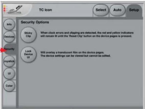
text_image
TC Icon Select Auto Setup Info Devices Security Joystick UI Color Security Options Sticky Clip When clock errors and clipping are detected, the red and yellow indicators will remain lit until the 'Reset Clip' button on the device pages is pressed. Lock Device UR Will overlay a translucent film on the device pages. The device settings can be viewed but cannot be edited.On the security page, you can set several features regarding device readouts and operation.
- Sticky Clip button – Click the Sticky Clip button to activate or deactivate the Sticky Clip feature.
- When the Sticky Clip feature is activated (button highlighted) and clock errors or clippings are detected in a device, the red and yellow warning indicators will remain lit until the user presses "Reset Clip" button. This feature ensures that clock errors or clippings do not go unnoticed.
- Lock Device UI button – Click the Lock Device UI button to lock or unlock the user interfaces of the devices controlled by the TC Icon software.
- When the Lock Device UI feature is activated (button highlighted), the user will be able to see the settings of the currently selected device, but he cannot change them. This will be indicated by a semi-transparent overlay and a "Device UI is locked" message on all device-related screens.

text_image
Reverb Twen Device UI is locked Name Edit MainJoystick page
- The MIDI Joystick setup page of the TC Icon software is not required for operating Reverb TwentyFour and is not described in this manual.
9.4 UI page

text_image
TC electronic TC Icon Select Auto Setup Info Devices Security Joystick UI Color TC Icon Window Faders At Bottom Fader At Right Side No Faders Always On TopUse the 4 buttons to specify if and where the 6 faders should be shown. Changes on this page will take effect next time you open the TC Icon software.
- Faders at bottom setting – Faders will be positioned right below the main interface. This is the default setting.
- Fader at right side setting – One fader will be positioned to the right of the main interface.
- No faders setting – No faders will be shown on screen.
- Always On Top – the interface will always on top, and not hidden from view.
EN

9.5 Color page

text_image
TC Icon Select Auto Setup Info Color Scheme Pastel Silver Icon PCB Alpine Background Graphite Icon Panel Front Lago Verde Icon Panel Back Inglolstadt Device Panel Front Black Ice Device Panel Back Deep Space Text Gold User scheme 1 User scheme 2 User scheme 3 User scheme 4 User scheme 5 User scheme 6 R: 108 G: 112 B: 112 Color User scheme 1 User scheme 2 User scheme 3 User scheme 4 User scheme 5 User scheme 6Use the Color page to define the TC Icon software's interface colors.
- Color Scheme parameter – Use the Color Scheme parameter to select a predefined color scheme. You can select a predefined color scheme from the list or define your own color scheme using one of the "User scheme" slots.
-
Color Element parameters – Use the Color Element parameters to customize the colors of the currently selected User scheme. You can change the colors used for:
-
Background.
- Icon Panel Front.
- Icon Panel Back.
• Device Panel Front.
• Device Panel Back. - User Interface Text.
We suggest changing these colors under realistic/typical lighting conditions to make sure the interface is easy to read during day-to-day use.
Changing User scheme colors
- To change the color, select a User Interface Scheme in the Color Scheme list and adjust each Color Element (e.g. Background) using the three R(ed), G(reen), and B(lue) faders that appear.
- To apply the new color scheme, click the "Apply User Scheme" button on the right.
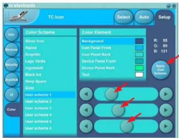
text_image
TC icon Select Auto Setup Info Devices Security Joystick UI Color Color Scheme Silver Icon Alpine Graphite Lago Verde Ingolstadt Black ice Deep Space Gold User scheme 1 User scheme 2 User scheme 3 User scheme 4 User scheme 5 User scheme 6 Color Element Background Icon Panel Front Inuit Panel Back Device Panel Front Device Panel Back Text R: 55 G: 89 B: 131 Apply User Scheme10. Using Reverb TwentyFour
The Reverb TwentyFour comes pre-loaded with many factory presets for scenes, routings, and the Engines. These may be viewed using the Library/Recall page.
Details of the factory presets are shown on page 37. Here are a few example pages:
Factory Scene Presets
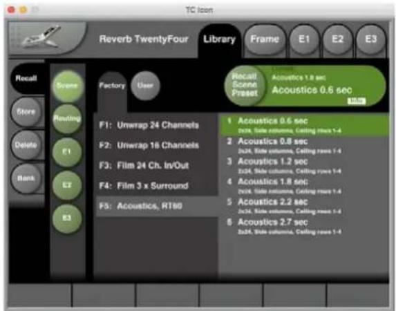
text_image
TC Icon Reverb TwentyFour Library Frame E1 E2 E3 Recall Scene Store Routing Delete Bank E1 E2 E3 Factory User F1: Umwrap 24 Channels F2: Umwrap 16 Channels F3: Film 24 Ch. In/Out F4: Film 3 x Surround F5: Acoustics, RT100 Recall Scene Preset Acoustics 1.8 sec Acoustics 0.6 sec Acoustics 0.6 sec Acoustics 0.8 sec Acoustics 1.2 sec Acoustics 1.8 sec Acoustics 2.2 sec Acoustics 2.7 sec Acoustics 2.2 sec Acoustics 2.7 secFactory Routing Presets

text_image
TC Icon Reverb TwentyFour Library Frame E1 E2 E3 Recall Scene Store Routing Delete Bank Factory User F1: Mono, Stereo, 24 F2: 5.1 surround F3: 7.1 surround Recall Routing Preset Unwrap 7x2H SMPTE 1 in, 24 out 1 in, 24 out Ch 1 in, 1-04 out, SMPTE 7.1 2 in, 24 out Ch 1-2 in, 1-24 out, SMPTE 7.1 3 in, 24 out Ch 1-24 Inout, SMPTE 7.1 4 Empty Routing Remove all Inset ceilingsFactory Engine Presets (E1 shown)
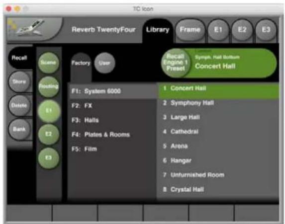
text_image
TD icon Reverb TwentyFour Library Frame E1 E2 E3 Recall Scene Store Routing Delete Bank E1 E2 E3 Factory User F1: System 6000 F2: FX F3: Halls F4: Plates & Rooms F5: Film Recall Engine 1 Preset Sympa. Hall Bottom Concert Hall 1 Concert Hall 2 Symphony Hall 3 Large Hall 4 Cathedral 5 Arena 6 Hangar 7 Unfurnished Room 8 Crystal HallAbout the Scene Presets
Details of the Factory Scene Presets supplied with the Reverb TwentyFour are shown in section 16.1 on page 37.
Flexible routing options
Of course, the input does not have to be a mono signal. Feeding stereo, 5.1, 6.1, 7.1 or x-to-x channel stems is easy using the Reverb TwentyFour's routing matrix.

text_image
TC Icon Reverb TwentyFour Library Frame E1 E2 E3 Routing E1 MADI Channel Routing Eng. 1 Ch. MAGI In Ch. 1 MAGI Out Ch. 1 E1-3 E2 1 1 1 System E3 Input 1: 1 7 3 2: 3 3: 2 4: 5 5: 6 6: 7 7: 7 8: 8 Output 1: 1 2: 3 3: 2 4: 5 5: 6 6: 7 7: 4 8: 8 Eng. 1 Ch. MAGI In Ch. 1 MAGI Out Ch. 1 1 1 1EN
Topologies: Surround, Rows, Columns
When connecting Reverb TwentyFour to the physical inputs and outputs on the Routing page, note that I/O numbers depend on the topology you have chosen. Use the "Assignment" parameter on the Rev page to set the topology.
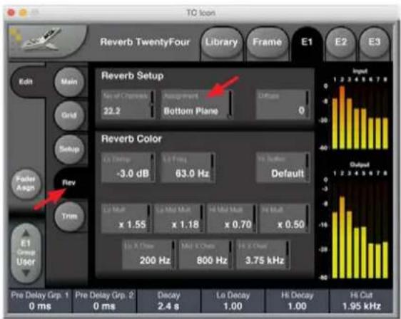
text_image
TO Icon Reverb TwentyFour Library Frame E1 E2 E3 Edit Main Grid Setup Polar Assign Rev Trim ET Group User Reverb Setup No of Channels Assignment Diffuse 22.2 Bottom Plane 0 Reverb Color Lo Change Lo Pull In Button -3.0 dB 63.0 Hz Default Lo Mut Lo Mid Mut Hi Mid Mut Hi Mid x 1.55 x 1.18 x 0.70 x 0.50 Lo X Close Mid X Chats Hi X Close 200 Hz 800 Hz 3.75 kHz Pre Delay Grp. 1 Pre Delay Grp. 2 Decay Lo Decay Hi Decay Hi Cut 0 ms 0 ms 2.4 s 1.00 1.00 1.95 kHzThe topologies to choose from include:
• Surround, Rows, Columns.
- Layers, Planes.
Each of these topologies uses the I/O numbers differently.
The currently selected topology is always shown on the Grid page.
Reverb TwentyFour and its factory presets are forgiving on speaker placement — but presets expect all channels to produce the same SPL for a certain signal. In case speakers are not aligned in level, offsets should be applied on the Trim page of the Reverb TwentyFour.
22.2 in/22.2 out Routing Preset
The 22.2 in/ 22.2 Routing preset settings and channel assignments are shown in detail on page 39.
Using the Main and Grid pages
Load one of the factory presets into an Engine and go to its Main page. In this example, we have chosen Engine E1, and preset "Symph. Hall Bottom."

text_image
TC-Ion Reverb TwentyFour Library Frame E1 E2 E3 Edit Main Name Algorithm Symph. Hall Bottom Reverb8 Levels 0.0 dB Off 50% Cap Level Grp. 1 0.0 dB Mute Grp. 1 Cap Level Grp. 2 0.0 dB Mute Grp. 2 Pre Delay Pre Delay Grp. 1 0 ms Zero Grp. 1 Pre Delay Grp. 2 0 ms Zero Grp. 2 Pre Delay Grp. 1 0 ms Decay 2.4 s La Decay 1.00 Hi Decay 1.00 Hi Cut 1.95 kHz Input OutputThe most important pages for quick edits are Main and Grid.
- On the Main page, use Groups to quickly balance levels and adjust timing, or make A/B comparisons using the Mute and Zero functions. See "Main page" (page 32).
- On the Grid page, use the graphic display to weigh reverb parameters using an intuitive, visual approach – see "Using the Grid" below.
Please note that there are always two Groups of Channels. You assign Channels to these Groups on the Setup page – see "Setup page" on page 34.
In all factory presets, channels 1 to 3 are assigned to Group 1, while all other channels are assigned to Group 2.
Using the Grid
The Grid page provides a new approach to multichannel editing. The four parameters shown below the Grid can quickly be varied across the algorithm's channels by offsetting a dot from its center position.
• Select one of the four parameters shown below the Grid:
-
Decay.
• Lo Decay.
Hi Decay.
Hi Cut. -
A green dot in the actual Grid will now represent the selected parameter's status.
• Set the selected parameter to a base value. - Click the Reset button to center the dot and set the associated parameter to the same value on all channels, or:
- Move the dot to obtain the variation required.
- Reverb TwentyFour provides decorrelated outputs, whether the Grid parameters are set to the same setting or not.
In the Grid example below, the Grid has the Assignment parameter set to Surround, and the Hi Cut parameter has been selected and moved towards the center of the grid.
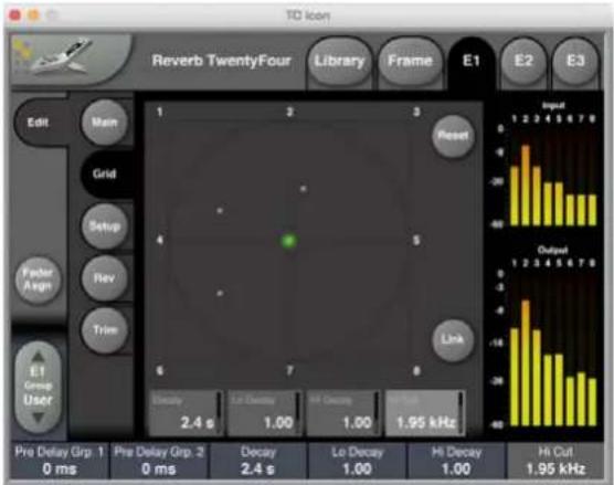
text_image
TD Icon Reverb TwentyFour Library Frame E1 E2 E3 Edit Main Grid Setup Rev Trim E1 Group User Pre Delay Grp. 1 0 ms Pre Delay Grp. 2 0 ms Decay 2.4 s Le Decay 1.00 Hi Decay 1.00 Hi Cut 1.95 kHz Reset Output Input -60 -40 -20 -10 -5 -3 -1 -4 -6 -8 -10 -12 -14 -16 -18 -20 -22 -24 -26 -28 -30 -32 -34 -36 -38 -40Grid setup
What happens when the dot in the Grid is moved off-center is defined in the "Grid Setup" section of the Setup page. This Setup page example shows the typical Groups for Surround Mode and Grid Setup used on most factory presets.

text_image
TC Icon Reverb TwentyFour Library Frame E1 E2 E3 Edit Main Grid Grid Setup Decay Pitch 50% Decay Pulse Wide Lo Decay Pitch 100% Lo Decay Pulse Default Hi Decay Pitch 100% Hi Decay Pulse Default Hi Cut Pitch -50% Hi Cut Pulse Wide Group 1 Ch. 1 Ch. 2 Ch. 3 Ch. 4 Ch. 5 Ch. 6 Ch. 7 Ch. 8 Group 2 = Not 1 Input Output Pre Delay Grp. 1 0 ms Pre Delay Grp. 2 0 ms Decay 2.4 s Lo Decay 1.00 Hi Decay 1.00 Hi Cut 1.95 kHzDecay Res. parameters
If you were to move the dot in the previous grid page towards the channel 8, then with the Decay Res. parameter on the Setup page set to the "Default" setting, the decay time of channel 8 would be much longer than the rest, channel 5 and 7 somewhat longer, and channel 3 and 6 a bit longer. For a more detailed explanation, see the following section.
A setting of 50 % for the Decay Res. parameter means that moving the dot from the center towards a channel will prolong the previously set Reverb Decay time by 50 %.
Focus parameters
The Decay Focus, Lo Decay Focus, Hi Decay Focus, and Hi Cut Focus parameters on the Setup page determine how strongly neighboring channels are affected when the dot is moved toward one channel.
- Narrow: There is only a limited influence on the neighboring channel(s).
- Default: The neighbor channels are influenced, and a bit of influence is also applied to their next neighbor.
- Wide: Similar to Default, but the effect on the respective channels is more pronounced.
Focus may also be set to:
• "FB Only" (Front/Back only) or:
• "LR Only" (Left/Right only).
Those settings provide the same off-center adjustments to all channels in either the Front/ Back or the Left/Right plane.
Resolution and Focus settings may be changed before or after adjusting the Grid. For example, with the scenario shown above, if Decay Res. were changed to -75%, the decay in channels 8, 5 and 7 (direct neighbors), 6 and 3 (neighbors' neighbors) would become much shorter than the remaining channels.

11. Main page
Go to E1/Main to reach the main page of Engine 1. The details of each area of the main page is described below:
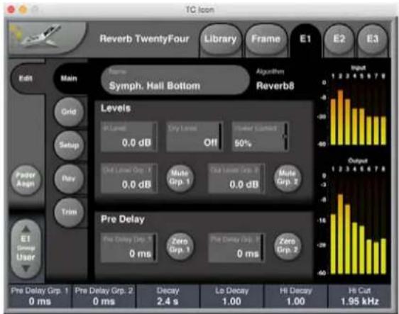
text_image
TC Icon Reverb TwentyFour Library Frame E1 E2 E3 Edit Main Grid Setup Rev Trim Symph. Hall Bottom Algorithm Reverb8 Levels In Level 0.0 dB Dry Level Off Power Current 50% Chrd Level Grp. 1 0.0 dB Mute Grp. 1 Chrd Level Grp. 2 0.0 dB Mute Grp. 2 Pre Delay Pre Delay Grp. 3 0 ms Zero Grp. 1 Pre Delay Grp. 2 0 ms Zero Grp. 2 Output 1 2 3 4 5 6 7 8 Pre Delay Grp. 1 0 ms Pre Delay Grp. 2 0 ms Decay 2.4 s Le Decay 1.00 Hi Decay 1.00 Hi Cut 1.95 kHzName
- Use the Name field in the top area to edit the name of the currently selected Preset. It can then be saved as a user preset once you have set it up.
11.1 Levels Section
In Level
• Range: Off, -115,5 to 0 dB.
• Use the In Level parameter to set and adjust the input level.
Dry Level
• Range: Off, -115,5 to 0 dB.
- Use the Dry Level parameter to set the level of the dry, unprocessed signal that should be passed to the output channels.
Power Correct
• Range: Off, 50 % and 100 %.
- As Reverb Decay times gets longer, the Power Correct feature can be used to lower the gain, thereby keeping the power of the Reverb constant. This feature is typically a big help when mixing because trimming of Decay is more forgiving (as the dry/wet balance doesn't change).
Out Level Group 1 and Out Level Group 2
• Range: Off, -115,5 to 0 dB.
- Use the Out Level Group 1 and Out Level Group 2 parameters to set the output levels of the reverb channels assigned to Group 1 and Group 2. You assign Reverb Channels to the two Groups on the Setup page.
Mute Group 1 and Mute Group 2 button
- Use the Mute Group 1 and Mute Group 2 buttons to temporarily mute all Reverb Channels assigned to Groups 1 and 2.
11.2 Pre Delay Section
Pre Delay Group 1 and Pre Delay Group 2
• Range: 0 to 150 ms.
- Use the Pre Delay Group 1 and Pre Delay Group 2 parameters to apply a pre-delay to the Reverb Channels assigned to Groups 1 and 2.
- Please note that in addition to these Pre Delay Group parameters, each Reverb Channel can be delayed individually using the eight Ch. parameters in the Delay Trim section of the Trim page.
Zero Group 1 and Zero Group 2 buttons
- Use the Zero Group 1 and Zero Group 2 buttons to temporarily remove the delay from the Reverb Channels assigned to Groups 1 and 2.
12. Grid page
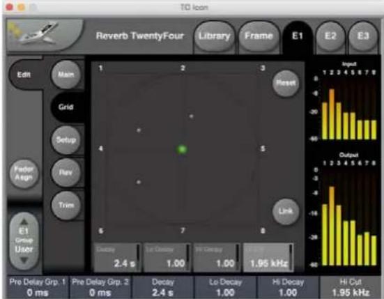
text_image
Reverb TwentyFour Library Frame E1 E2 E3 Edit Main Grid Setup Forder Assign Trim E1 Group User Pre Delay Grp. 1 0 ms Pre Delay Grp. 2 0 ms Decay 2.4 s Decay 2.4 s Lo Decay 1.00 Hi Decay 1.00 Hi Cut 1.95 kHz Reset Link Output Input -8 -60 -40 -20 -10 -5 -3 -1 -7 -4 -2 -1 -3 -5 -7 -9 -60 -40 -20 -10 -5 -3 -1 -7 -4 -2 -1 -3 -5 -7 -9For a description of how to use the Grid, please see the previous section "Using the Grid" (page 30).
Reset button
- To reset the position of the green selector dot for the currently selected parameter to Zero (center of grid), click the Reset button.
Decay
• Range: 0.1 to 20 s.
- Use the Decay parameter to define the basic decay time of the Reverb TwentyFour. This is defined as the time it takes the Reverb to decay 60 dB. The Decay times for all eight Reverb channels, as defined by the position of the green dot on the Grid page, refer to the setting of this parameter. This means that when the Decay parameter is selected and the green dot is centered in the Grid, the Reverb Decay time for all eight Channels will be the value shown for this parameter.
Lo Decay
- Range: 0.5 to 2.0.
-
Use the Lo Decay parameter to define the decay time for the lower frequencies of the reverb. This parameter acts as a multiplier to the Lo Mult. and Lo Mid Mult. parameters in the Reverb Color section on the Rev page.
Example: -
Let us assume the Decay parameter on the Grid page is set to 2.0 seconds – this is the "base" decay time.
- On the Rev page, you have set the Low Mult. parameter to 1.5. This means that the decay time for the low frequency band (as defined by the Lo X Over parameter) is (2 x 1.5 =) 3.0 seconds.
- You have also set Lo Mid Mult. on the Rev page to 2.5. Accordingly, the decay time for the low mid frequency band is now (2 x 2.5 =) 5.0 seconds.
- Now if you set Lo Decay on the Grid page to 2 and move the green dot all the way towards one channel in the grid, this will have the following effect for this particular channel:
• Decay for the low frequency band: (2 × 1.5 × 2 =) 6 seconds.
• Decay for the low-mids frequency band: (2 × 2.5 × 2 =) 10 seconds.
Put more simply: The parameters on the Rev page set the basic character of the reverb, allowing you to use the Grid as a wider "paint brush" for customizing/weighing the base settings as required.
Hi Decay
Range: 0.5 to 2.0.
- Use the Hi Decay parameter to define the decay time for the higher frequencies of the reverb. This parameter acts as a multiplier to the Hi Mid Mult. and Hi Mult. parameters in the Reverb Color section on the Rev page.
The interaction between the four involved parameters (Decay and Hi Decay on the Grid page, Hi Mid Mult. and Hi Mult. on the Rev page) is the same as for the low and low mid frequency bands described in the example for the Lo Decay parameter above.
Tip: When you are creating new Reverb TwentyFour presets, be sure to start by setting the Lo Decay and Hi Decay parameters to "1" first. This way, you enjoy the greatest flexibility when you edit and "play" your Reverb Preset later using the Grid.
Hi Cut
• Range: 20 Hz to 20 kHz.
- Use the Hi cut parameter to define the cutoff frequency for the high-cut filter applied to the reverb. The filter frequencies applied to all eight Reverb channels as defined by the position of the green dot on the Grid page refer to the setting of this parameter.

13. Setup page

text_image
TC Ion Reverb TwentyFour Library Frame E1 E2 E3 Edit Main Grid Setup Fader Assign Trim E1 Group User Grid Setup Change From: 50% Wide Lo Decay From: 100% Default Hi Decay From: 100% Default Hi Cut From: -50% Wide Group 1 Ch. 1 Ch. 2 Ch. 3 Ch. 4 Ch. 5 Ch. 6 Ch. 7 Ch. 8 Group 2 = Not 1 Input Output Pre Delay Grp: 1 0 ms Pre Delay Grp: 2 0 ms Decay 2.4 s Lo Decay 1.00 Hi Decay 1.00 Hi Cut 1.95 kHz13.1 Grid Setup section
Decay Res.
• Settings: -75 / -50 / -25 / 0 / 25 / 50 / 100 %.
- Use the Decay Res. parameter to define how moving the green dot towards one of the eight Grid Markers affects the overall Reverb decay for the respective Reverb channel and its neighbors on the Grid.
- Negative values will shorten the Reverb decay, a neutral setting means that Reverb decay is not affected, and positive values will increase the Decay time by up to 100 % when the green dot is moved toward a Grid Marker.
Decay Focus
• Settings: Narrow / Default / Wide / LR Only / FB Only.
- Use the Decay Focus parameter to specify to what degree moving the green dot in the Grid affects the Decay times for neighboring channels. See "Grid setup – Focus parameters" (page 31).
Lo Decay Res.
• Settings: -75 / -50 / -25 / 0 / 25 / 50 / 100 %.
- Use the Lo Decay Res. parameter to define how moving the green dot towards one of the eight Grid Markers affects the decay of the Reverb's low frequency component for the respective Reverb channel and its neighbors on the Grid. Negative values will shorten the decay time, positive values will increase it.
Lo Decay Focus
• Settings: Narrow / Default / Wide / LR Only / FB Only.
- Use the Lo Decay Focus parameter to specify to what degree moving the green dot in the Grid affects the Lo Decay times for neighboring channels. See "Grid setup – Focus parameters" (page 31).
Hi Decay Res.
• Settings: -75 / -50 / -25 / 0 / 25 / 50 / 100 %.
- Use the Hi Decay Res. parameter to define how moving the green dot towards one of the eight Grid Markers affects the decay of the Reverb's high frequency component for the respective Reverb channel and its neighbors on the Grid. Negative values will shorten the decay time, positive values will increase it.
Hi Decay Focus
• Settings: Narrow / Default / Wide / LR Only / FB Only.
- Use the Hi Decay Focus parameter to specify to what degree moving the green dot in the Grid affects the Hi Decay times for neighboring channels. See "Grid setup – Focus parameters" (page 31).
Hi Cut Res.
• Settings: -75 / -50 / -25 / 0 / 25 / 50 / 100 %.
- Use the Hi Cut Res. parameter to define how moving the green dot towards one of the eight Grid Markers affects the high frequency filter applied to the reverb for the respective Reverb channel and its neighbors on the Grid.
Hi Cut Focus
• Settings: Narrow / Default / Wide / LR Only / FB Only.
- Use the Hi Cut Focus parameter to specify to what degree moving the green dot in the Grid affects the high-cut filter applied to the neighboring channels. See "Grid setup — Focus parameters" (page 31).
13.2 Group 1 section
- Use the Group 1 section of the Setup page to specify the Reverb channels that should belong to Reverb Channel Group 1 by clicking the respective buttons.
- All Reverb channels that are not assigned to Reverb Channel Group 1 automatically become part of Reverb Channel Group 2.
- Use the two Reverb Channel Groups to control complex Reverbs more effectively.
14. Rev page

text_image
TC Icon Reverb TwentyFour Library Frame E1 E2 E3 Edit Main Grid Setup Feder Assign Rev Trim E1 Group User Reverb Setup No of Channels Assignment Diffuse 22.2 Bottom Plane 0 Reverb Color La Delta La Freq Hi Bottom -3.0 dB 63.0 Hz Default Lo Shift Lo Mid Shift Hi Mid Shift Hi Shift x 1.55 x 1.18 x 0.70 x 0.50 Lo Shift Mid X Over Fi X Over 200 Hz 800 Hz 3.75 kHz Pre Delay Grp. 1 0 ms Pre Delay Grp. 2 0 ms Decay 2.4 s Lo Decay 1.00 Hi Decay 1.00 Input Output Hi Cut 1.95 kHzThe Rev page is used for basic setup and color adjustment of the reverb. When producing more output channels than 8, be sure to have Assignment set correctly, i.e. to different Planes (ITU 22.2) or to different Layers (all other formats).
It is fine to combine a Layer 1 Surround in one Engine with a Layer 2 Column in another Engine but different instances of Reverb TwentyFour should always be set to different Layers.
14.1 Reverb Setup section
No of Channels
Settings: 5-16, 22.2, 16-24.
Use the "No of Channels" parameter to define the total number of Reverb channels you will create:
- With the No of Channels parameter set to 5–16, you can use the Assignment parameter (right next to it) to assign each Engine E1, E2, or E3 to Layer 1 or 2 of a particular topology (Surround, Row or Column) — see "Topologies: Surround, Rows, Columns" (page 30).
- With the No of Channels parameter set to 22.2, you can use the Assignment parameter to assign each Engine E1, E2, or E3, to one of the three planes (Bottom/Mid/Top) – see "Description of the 22.2 in/22.2 out Routing Preset" on page 39.
- With the No of Channels parameter set to 16-24, you can use the Assignment parameter to assign each Engine E1, E2, or E3 to Layer 1, 2 or 3 of a particular topology (Row or Column).
Assignment
• Range: Depending on setting of No. of Channels parameter.
- Use the Assignment parameter to assign every instance to a particular Layer or Plane. Make sure that you do not set multiple instances to the same Layer.
The available settings are:
- With the No of Channels parameter set to 5-16: Layer 1 Surround, Layer 2 Surround, Layer 1 Row, Layer 2 Row, Layer 1 Column, Layer 2 Column.
- With the No of Channels parameter set to 22.2: Bottom Plane, Mid Plane, Top Plane.
- With the No of Channels parameter set to 16-24: Layer 1 Row, Layer 2 Row, Layer 3 Row, Layer 1 Column, Layer 2 Column, Layer 3 Column.
Diffuse
Range: -16 to 16.
- Use the Diffuse parameter to apply more or less diffusion to the reverb than the algorithm designer intended for the given Decay time. For optimum performance, the diffusion is automatically adjusted "behind the scenes" whenever you change decay time. This parameter gives you added control to vary the diffusion around this automatic setting.
14.2 Reverb Color section
Lo Damp
• Range: -18 to 0 dB.
- Reverb TwentyFour is equipped with an adjustable low-cut filter that allows you to remove low frequencies from the Reverb. Use the Lo Damp parameter to set the amount of cut.
Lo Freq
• Range: 20 to 200 Hz.
- Use the Lo Freq parameter to set the filter frequency for Reverb TwentyFour's low-cut filter.
Hi Soften
• Range: -50 to 50.
- Hi Soften is a special filter used to "soften" the high frequencies of Reverb TwentyFour. This is not a simple high-cut filter, but a complex set of filters working together to remove those frequencies that make a reverb sound "brittle" or harsh.
Lo Mult.
- Range: 0.01 to 2.5.
- Use the Lo Mult. parameter to define a multiplier for the frequencies below the Lo X Over frequency.
- For example: If the main Decay parameter on the Grid page is set to 2 seconds, and the Lo Mult. parameter is set to 1.5, frequencies below the Lo Xover frequency will decay for 3 seconds.
Lo Mid Mult.
• Range: 0.01 to 2.5.
- Use the Lo Mid Mult. parameter to define a multiplier for the frequencies below the Mid X Over frequency.
Hi Mid Mult.
• Range: 0.01 to 2.5.
- Use the Hi Mid Mult. parameter to define a multiplier for the frequencies below the Mid X Over frequency.
Hi Mult.
• Range: 0.01 to 2.5.
- Use the Hi Mid Mult. parameter to define a multiplier for the frequencies above the Mid X Over frequency.

Lo X Over
• Range: 20 to 500 Hz.
- Use the Lo X Over parameter to define the crossover frequency from the Low Frequency band to the Low Mid Frequency band.
Mid X Over
• Range: 200 Hz to 2 kHz.
- Use the Mid X Over parameter to define the crossover frequency from the Low Mid Frequency band to the High Mid Frequency band.
Hi X Over
• Range: 689 Hz to 20 kHz.
- Use the Hi X Over parameter to define the crossover frequency from the High Mid Frequency band to the High Frequency band.
15. Trim page
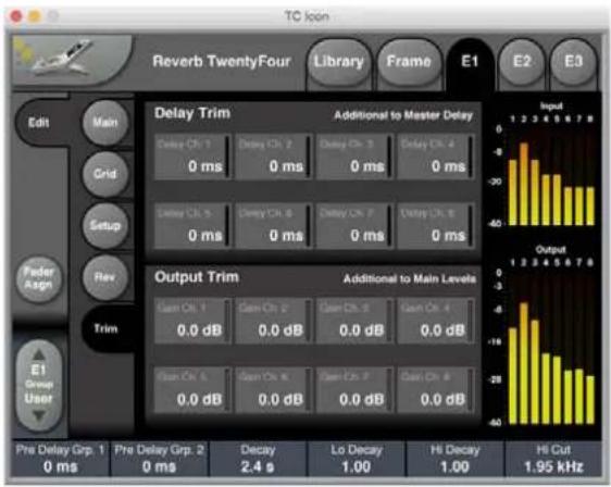
text_image
TC Icon Reverb TwentyFour Library Frame E1 E2 E3 Edit Main Grid Setup Rev Feder Assign Trim E1 Group User Delay Trim Additional to Master Delay Delay Ch: 1 0 ms Delay Ch: 2 0 ms Delay Ch: 3 0 ms Delay Ch: 4 0 ms Delay Ch: 5 0 ms Delay Ch: 6 0 ms Delay Ch: 7 0 ms Delay Ch: 8 0 ms Output Trim Additional to Main Levels Gain Ch: 1 0.0 dB Gain Ch: 2 0.0 dB Gain Ch: 3 0.0 dB Gain Ch: 4 0.0 dB Gain Ch: 5 0.0 dB Gain Ch: 6 0.0 dB Gain Ch: 7 0.0 dB Pre Delay Grp. 1 0 ms Pre Delay Grp. 2 0 ms Decay 2.4 s Lo Decay 1.00 Hi Decay 1.00 Hi Cut 1.95 kHzLevel trims and Delay offsets per output are available on the Trim page. All parameters are additive to Level and Pre Delay settings on the Main page.
15.2.1 Delay Trim section
Delay Ch. 1 / 2 / 3 / 4 / 5 / 6 / 7 / 8
• Range: 0 to 120 ms.
- Use the Delay Ch. 1 to Delay Ch. 8 parameters in the Delay Trim section to delay each Reverb Channel by up to 120 milliseconds.
- These delay values are applied in addition to the Pre Delay Group 1 and 2 values set on the Main page – see "Pre Delay section" (page 32).
15.2.2 Output Trim section
Gain Ch. 1/2/3/4/5/6/7/8
• Range: Off, -115,5 to 0 dB.
- Use the Gain Ch. 1 to Gain Ch. 8 parameters in the Output Trim section to attenuate each Reverb Channel.
- The Level reduction for each Channel as defined on this page is added to the Out Level Group 1 and Out Level Group 2 values set on the Main page — see "Levels section" (page 32).
16. Factory presets
16.1 Scene Presets
There are five scene preset groups F1 to F5, each with a number of presets.
To review the available factory scene presets, go to Library/Recall/Scene and select the "factory" button.

text_image
TC Icon Reverb TwentyFour Library Frame E1 E2 E3 Recall Scene Routing E1 E2 E3 Factory User F1: Unwrap 24 Channels F2: Unwrap 16 Channels F3: Film 24 Ch. In/Out F4: Film 3 x Surround F5: Acoustics, RT60 Recall Scene Preset Current Acoustics 1.8 sec Acoustics 0.6 sec Info 1 Acoustics 0.6 sec 2x24, Side columns, Ceiling rows 1-4 2 Acoustics 0.8 sec 2x24, Side columns, Ceiling rows 1-4 3 Acoustics 1.2 sec 2x24, Side columns, Ceiling rows 1-4 4 Acoustics 1.8 sec 2x24, Side columns, Ceiling rows 1-4 5 Acoustics 2.2 sec 2x24, Side columns, Ceiling rows 1-4 6 Acoustics 2.7 sec 2x24, Side columns, Ceiling rows 1-4| Group Presets Notes | ||
| F1: Unwrap24 channels | Presets intended for going to 24 channels from mono, stereo, 5.1 or 7.1 channel inputs“Symphony Hall” preset with routing 1 to 24, 2 to 24, 5 to 24 and 7 to 24“Old Theatre” preset with same routing as “Symphony Hall”: 1 to 24, 2 to 24, 5 to 24 and 7 to 24 | The 3 layers are tuned individually for best experience of the 24 speakers.The routing follows 3 times 7.1 SMPTE input channel order L-R-C-(LFE)-Lss-Rss-Lsr-RsrThe LFE input channel is not usedOutput channel order is 3 times: L - R - C - BC (back center) -Lss-Rss-Lsr-RsrThe rear center channel in each layer is fed by either rear L or R input channelWith stereo input L and R is feeding the reverb in a "random" pattern so the 24 channels reverb is using less of the original stereo information. Use as an example - other input routing may fit the input material betterInput routing is included as an example and works well with some 5.1 stems. Optimum routing depends on type of input. In some situations a stem downmix to stereo or to LtRt can give a more satisfactory result |
| Group Presets Notes | ||
| F2: Unwrap16 channels | Same as Unwrap to 24, but only the Mid and Top layer settings are used | |
| F3: Film24 Ch. In/Out | Specifical tunings for typical film use.24 channel in/out presets | The Film scene presets are based on the "Film"Engine presets3 presets are "stacked" with adjusted settings and different speaker assignments ensuring a 24 fully decorrelated channels experienceThe routing follows 3 times7.1 SMPTE input channel orderL-R-C-(LFE)-Lss-Rss-Lsr-RsrOutput channel order is3 times: L - R - C - BC (back center) -Lss-Rss-Lsr-RsrOn the input the LFE channel is not usedUse e.g. Dedicated 22.2routing presets to make the preset compatible with ITU 22.2 setups |
| F4: Film3 x Surround | Different Film production examples with 3 x surround presets for both5.1 and 7.1 with different channel order standards | Channel order: SMPTE and FILM, 5.1 and 7.17.1 SMPTE channel orderL-R-C-(LFE)-Lss-Rss-Lsr-Rsr5.1 SMPTE channel orderL-R-C-(LFE)-Lsr-Rsr7.1 FILM channel orderL-C-R-Lss-Rss-Lsr-Rsr-(LFE)5.1 FILM channel orderL-C-R-Lsr-Rsr-(LFE) |
| F5: Acoustics, RT60 | This Presets Group supports acoustics enhancement. The group contains 6 presets for different decay times:0.6, 0.8, 1.2, 1.8, 2.2 and 2.7 sec.RT60 is the time it takes for the sound to decay by 60 dB after the sound source stops. | Acoustics 0.6 sec2x24, Side columns, ceiling rows 1-4Acoustics 0.8 sec2x24, Side columns, ceiling rows 1-4Acoustics 1.2 sec2x24, Side columns, ceiling rows 1-4Acoustics 1.8 sec2x24, Side columns, ceiling rows 1-4Acoustics 2.2 sec2x24, Side columns, ceiling rows 1-4Acoustics 2.7 sec2x24, Side columns, ceiling rows 1-4 |
EN
16.2 Routing Presets
There are three routing preset groups F1, F2, F3, each with a number of presets to select.
To review the available factory routing presets, go to Library/Recall/Routing and select the "factory" button.

text_image
Reverb TwentyFour Library Frame E1 E2 E3 Recall Scene Store Routing Delete Bank Factory User F1: Mono, Stereo, 24 F2: 5.1 surround F3: 7.1 surround Recall Routing Prset Unwrap 7x24 SMPTE 1 in, 24 out 1 in, 24 out Ch 1 in, 1-24 out, SMPTE 7.1 2 in, 24 out Ch 1-2 in, 1-24 out, SMPTE 7.1 3 in, 24 out Ch 1-24 out, SMPTE 7.1 4 Empty Routing Remove all outmost routings| Group Presets Notes | ||
| F1: Mono, Stereo, 24 | 1 in, 24 out, SMPTE 7.1 Unwrap from mono input to 24 channel output | |
| 2 in, 24 out, SMPTE 7.1 Unwrap from stereo input to 24 channel output | ||
| 24 in, 24 out, SMPTE 7.1 Use with full 24 channel mix stems. Routing is 3 × 7.1 SMPTE channel order | ||
| 22.2 in, 22.2 out, ITU-R BS.2159 | Use with full 22.2 channel mix stems. Routing is ITU-R BS.2159 channel order. Please see page 39 of this manual for more details. | |
| Empty Routing Removes all input and output routing | ||
| F2: 5.1 Surround | E1-E3 3x5.1 Setup for 5.1 for all 3 engines.SMPTE, FILM, DTS channel order avaliable | |
| Unwrap 5x24 Going from 5.1 input to 24 channel output. SMPTE, FILM, DTS input channel order avaliable | ||
| E1 5.1 Route 5.1 to/from E1. SMPTE and FILM channel order available | ||
| F3: 7.1 Surround | E1-E3 3x7.1 Setup for 7.1 for all 3 engines.SMPTE, FILM channel order avaliable | |
| Unwrap 7x24 Going from 7.1 input to 24 channel output. SMPTE, FILM input channel order avaliable | ||
| E1 7.1 Route 7.1 to/from E1. SMPTE and FILM channel order available | ||
16.2.1 Description of the 22.2 in/22.2 out Routing Preset
EN
22.2 standard channel layout ITU ITU-R BS.2159 Reverb Twenty Four
| Channel number | Label Name | Layer Engine | Engine Channel | MADI channel | Notes | ||
| 1 FL Front | Left Mid E2 4 1 | ||||||
| 2 FR Front | Right Mid E2 5 2 | ||||||
| 3 | FC | Front Centre | Mid | E2 | 2 | 3 | |
| 4 | LFE1 | LFE-1 | Bottom | E1 | 4 | 4 | Input not routed = output muted, can be fed carefully to LFE channel |
| 5 | BL | Back Left | Mid | E1 | 6 | 5 | |
| 6 | BR | Back Right | Mid | E1 | 8 | 6 | |
| 7 | FLc | Front Left Centre | Mid | E2 | 1 | 7 | |
| 8 | FRc | Front Right Centre | Mid | E2 | 3 | 8 | |
| 9 | BC | Back Centre | Mid | E1 | 7 | 9 | |
| 10 | LFE2 | LFE-2 | Bottom | E1 | 5 | 10 | Input not routed = output muted, can be fed carefully to LFE channel |
| 11 | SiL | Side Left | Mid | E2 | 6 | 11 | |
| 12 | SiR | Side Right | Mid | E2 | 8 | 12 | |
| 13 | TpFL | Top Front Left | Top | E3 | 1 | 13 | |
| 14 | TpFR | Top Front Right | Top | E3 | 3 | 14 | |
| 15 | TpFC | Top Front Centre | Top | E3 | 2 | 15 | |
| 16 | TpC | Top Centre | Top | E2 | 7 | 16 | |
| 17 | TpBL | Top Back Left | Top | E3 | 6 | 17 | |
| 18 | TpBR | Top Back Right | Top | E3 | 8 | 18 | |
| 19 | TpSiL | Top Side Left | Top | E3 | 4 | 19 | |
| 20 | TpSiR | Top Side Right | Top | E3 | 5 | 20 | |
| 21 | TpBC | Top Back Centre | Top | E3 | 7 | 21 | |
| 22 | BtFC | Bottom Front Centre | Bottom | E1 | 2 | 22 | |
| 23 | BtFL | Bottom Front Left | Bottom | E1 | 1 | 23 | |
| 24 | BtFR | Bottom Front Right | Bottom | E1 | 3 | 24 |
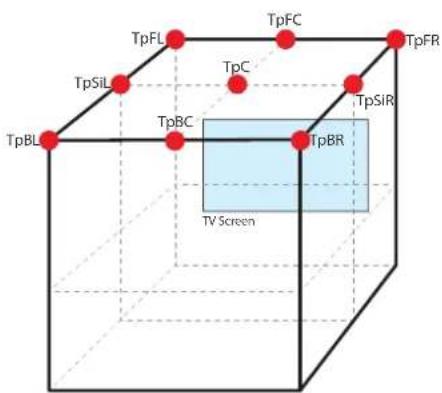
text_image
TpFL TpFC TpFR TpSiL TpC TpBR TpSIR TpBC TpBL TV Screen
text_image
FL SIL BL BC FLc FC FRc SIR BR FR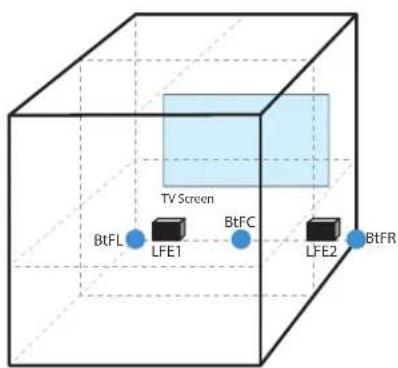
text_image
TV Screen BtFL LFE1 BtFC LFE2 BtFREN
16.3 Engine Presets
There are five factory preset groups F1, F2, F3, F4, F5, for each Engine, E1, E2, and E3. Each Factory preset group has 8 presets to select.
To review the available factory routing presets, go to Library/Recall/E1, E2, or E3 and select the "Factory" button.
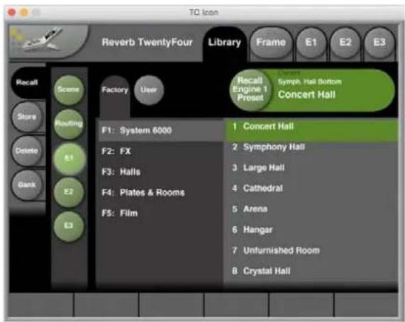
text_image
Reverb TwentyFour Library Recall Scene Store Routing Delete Bank Factory User F1: System 6000 F2: FX F3: Halls F4: Plates & Rooms F5: Film Recall Engine 1 Preset Symp. Hall Button Concert Hall 1 Concert Hall 2 Symphony Hall 3 Large Hall 4 Cathedral 5 Arena 6 Hangar 7 Unfurnished Room 8 Crystal Hall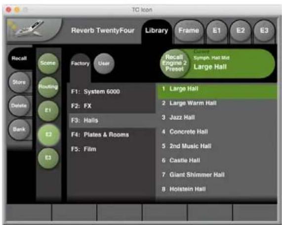
text_image
TC Icon Reverb TwentyFour Library Frame E1 E2 E3 Recall Scene Store Routing Delete Bank E1 E2 E3 Factory User F1: System 6000 F2: FX F3: Halls F4: Plates & Rooms F5: Film Recall Engine 2 Preset Large Hall Symph. Hall Mid Large Hall 1 Large Hall 2 Large Warm Hall 3 Jazz Hall 4 Concrete Hall 5 2nd Music Hall 6 Castle Hall 7 Giant Shimmer Hall 8 Holstein Hall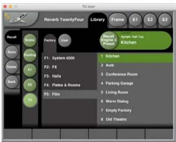
text_image
TC Icon Reverb TwentyFour Library Frame E1 E2 E3 Recall Scents Factory User Recall Engine 3 Preset Chicken Sympt Hall Top Kitchen Store Routing F1 System 6000 1 Kitchen Delete E1 F2: FX 2 Asia Bank E3 F3: Halls 3 Conference Room E4 F4: Plates & Rooms 4 Parking Garage E5 F5: Film 5 Living Room Warm Dialog Empty Factory 6 Warm Dialog Old Theatre 7 Empty Factory 8 Old Theatre| Group Presets Notes | ||
| F1: System 6000 | 8 presets | Factory presets from System 6000,Reverb 8 algorithm |
| F2: FX 8 presets | Different and funny FX presets with rather extreme settings | |
| F3: Halls 8 presets | A variety of surround Halls for both music and film | |
| F4: Plates & Rooms | 8 presets | A variety of surround plates and rooms for both music and film |
| F5: Film 8 presets | Specific tunings for typical film use | |
All engine presets are suitable for all surround formats but verified specifically in 5.1, 7.1 and 22.2.
An example of how to make reverb settings for more than 8 channels:
• Use an existing 8 channel engine preset or make your own in a 7.1 setup.
- Copy the 8 channel preset into the engines needed for the output format e.g. 3 engines for the 22.2 format. Now you have identical sound in all 24 channels but we need to make them uncorrelated.
- Use a suitable routing preset for the setup e.g. "22.2 in, 22.2 out".
- Adjust Engine 1 and 3, leaving Engine 2 as the reference.
- Set the No of Channels and Assignment on the Rev page differently in all 3 engines E.g. No of Channels = 22.2 and Assignment = Top, Mid and Bottom Plane respectively.
• Now the 24 output channels are completely de-correlated.
- Make adjustments in Engine 1 and 2 to precisely exploit the 22.2 speaker setup. For example, use slightly different Decay, Pre Delay, Hi Cut and Output Level settings in the 3 engines. More drastic adjustments may be used for your specific needs or your sound ideas.
17. System/ Remote
Go to Frame/System/Remote.
Remote features of the Reverb TwentyFour can be accessed through an external user-supplied interface connected to the rear panel GPIO port (see page 43 for details of the GPIO interface).
The Remote page of the TC Icon software has 3 main sections as follows:
- GPI – setup, choose, and enable different scene presets for remote recall. This may be used for quickly changing of the acoustics by changing the decay time in a venue. An external switch box can be made so the venue technicians have 3 buttons – one for each of 3 user scene presets that have different decay times. In this way you can select a decay time for the venue that fits the evening's concert type.
- Cal – calibrate the operation of the external equipment.
- GPO – this can be used if required, to setup operation of external LEDs.
17.1 Remote - GPI 1 - Scene Recall section
- GPI input 1 can be used for User Scene preset recall (see "Library – Recall page" on page 21). Please note that the Icon user interface is locked when GPI is used for control.
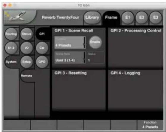
text_image
TC Icon Reverb TwentyFour Library Frame E1 E2 E3 Routing Status GPI E1-3 IPO Cat System Setup GPO Remote GPI 1 - Scene Recall 4 Presets Enable Scene Back Value User 3 (1-4) 1 GPI 2 - Processing Control GPI 3 - Resetting GPI 4 - Logging Function 4 PresetsEnable button
• Use this button to enable the GPI 1 input for User Scene Recall.
Current Scene Status field
- The Current Scene status field shows the name of the currently active Scene preset. The currently active Scene will be shown here wether it has been selected via GPI or not. The name shown here is identical to that shown on the Library – Recall – Scene page as "Current" and on top of the Frame – Routing page. When GPI is disabled, "-" is shown.
Function parameter
- Use the Function parameter to define the scope of the GPI recall feature. The available GPI recall modes that you can set using the Preset Recall Function parameter are:
• Off setting – No Preset Recall using GPI.
- 2 Presets – Select one of two Presets using GPI1. Select the Preset Bank using the Scene Bank parameter.
- 3 Presets – Select one of three Presets using GPI1. Select the Preset Bank using the Scene Bank parameter. For a description of the "Idle" state, see "Idle state" below.
- 4 Presets – Select one of four Presets using GPI1. Select the Preset Bank using the Scene Bank parameter.
- 7 Presets – Select one of seven Presets using GPI1. Select the Preset Bank using the Scene Bank parameter.
- 8 Presets – Select one of eight Presets using GPI1. Select the Preset Bank using the Scene Bank parameter.
- 3 Presets DUAL – Select one of three Presets using GPI1 and GPI2. This mode uses simple binary inputs on GPI1 and GPI2 – i.e. 00, 01, 10 and 11. Select the Preset Bank using the Scene Bank parameter.
- 4 Presets DUAL – Select one of four Presets using GPI1 and GPI2. This mode uses simple binary inputs on GPI1 and GPI2 – i.e. 00, 01, 10 and 11. Select the Preset Bank using the Scene Bank parameter.
- 15 Presets DUAL – Select one of fifteen Presets using GPI1 and GPI2. This mode uses 8-state on GPI1 and binary on GPI2. In this mode, the Scene Presets are always recalled from two consecutive banks – e.g. Bank 1 and Bank 2. Select the Preset Bank pairs (1+2, 3+4 etc.) using the Scene Bank parameter.
- 16 Presets DUAL – Select one of sixteen Presets using GPI1 and GPI2. This mode uses 8-state on GPI1 and binary on GPI2. In this mode, the Scene Presets are always recalled from two consecutive banks – e.g. Bank 1 and Bank 2. Select the Preset Bank pairs (1+2, 3+4 etc.) using the Scene Bank parameter.
Idle state
"Idle" denotes GPI control being presently not active – i.e. the unit can still be controlled as normal, adjusting parameters and recalling presets via the TC Icon. However, once a non-idle GPI state is chosen, the selected Scene preset is recalled, and normal functionality is blocked (which is also the case when GPI is engaged in general).
Scene Bank parameter
If you have set the previously-described Function parameter to any value other than "Off", you can select the Bank (or Banks) that Presets should be chosen from using the Scene Bank parameter. See the recall modes for a more thorough explanation.
Status field
• The status field is intended for diagnostics during the setup of GPI control.
- “-” — GPI 1 is not enabled, or the incoming voltage is outside of valid windows. Check the device's GPI calibration, the incoming voltage and the general external GPI setup.
- "Idle" — GPI is not controlling. The incoming GPI voltage may be at maximum or not connected while the current setting for the Scene Bank parameter in the same section includes the "idle" option.
- "1 (N/A)" – No valid User preset is stored in that specific library location, and therefore GPI is not controlling. The behavior of the device is identical to Idle state.
- "1, 2, 3, 4, 5, 6, 7, or 8" – Incoming GPI voltage is within the valid window, and GPI is controlling Scene Recall. The TC Icon UI is locked. Details regarding GPI signals: GPI 1 is receiving fixed-state, latching signals. A validation process is performed when receiving a new GPI voltage. The incoming voltage needs to be within the specific valid window for 500 ms before the preset change is initiated. The time required for performing a change depends on the scope of that change – e.g., whether it only involves parameters changes or the routing and algorithm change as well.
- For information on voltage windows and GPI circuits, please see page 43.
EN
17.2 Remote - Calibration
To calibrate GPI, go to the Frame / System / Remote/ Cal page.
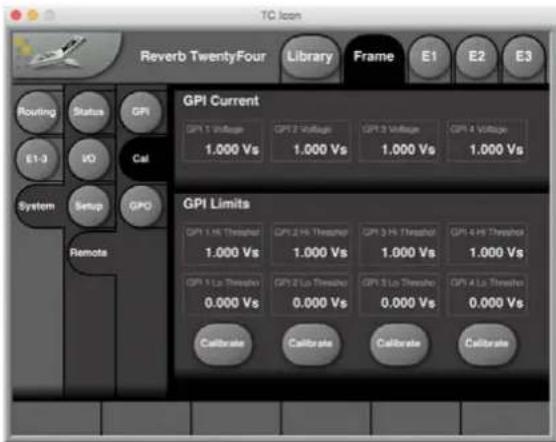
text_image
TC Icon Reverb TwentyFour Library Frame E1 E2 E3 Routing Status GPI EI-3 VO Cal System Setup GPO Remote GPI Current GPI 1 Voltage 1.000 Vs GPI 2 Voltage 1.000 Vs GPI 3 Voltage 1.000 Vs GPI 4 Voltage 1.000 Vs GPI Limits GPI 1 Hi Threshold 1.000 Vs GPI 2 Hi Threshold 1.000 Vs GPI 3 Hi Threshold 1.000 Vs GPI 4 Hi Threshold 1.000 Vs GPI 5 Lo Threshold 0.000 Vs GPI 6 Lo Threshold 0.000 Vs GPI 7 Lo Threshold 0.000 Vs GPI 8 Lo Threshold 0.000 Vs Calibrate Calibrate Calibrate CalibrateEach GPI may be used to switch between up to 8 states. GPI calibration should be performed when switching between more than two states (as it is required for preset recall).
Current section
- The Current section of the GPI Calibration page provides live status information for the GP inputs. Here, "Vs" denotes positive terminal on the respective GP connector, typically 3.3 V.
Limits section
- The Limits section of the GPI Calibration page shows the lower ("GPI Lo Threshold") and upper ("GPI Hi Threshold") limits of the voltage windows for the four GP inputs.
- To calibrate a GPI input, click the respective Calibrate button and follow the on-screen instructions.
17.3 GPIO Technical specifications
The General Purpose Input/Output (GPIO) connector on the Reverb TwentyFour rear panel is configured as follows:

text_image
5 4 3 2 1 10 6 15 14 13 12 11Pin No Function
| 1 GPO 1, contact 1 | |
| 2 GPO 2, contact 1 | |
| 3 GPI 2 | |
| 4 GPI 4 | |
| 5 3V3 output, 100 mA max | |
| 6 GPO 1, contact 2 | |
| 7 GPO 2, contact 2 | |
| 8 GPI 1 | |
| 9 GPI 3 | |
| 10 3V3 output, 100 mA max | |
| 11 Ground | |
| 12 Reserved | |
| 13 Ground | |
| 14 Ground | |
| 15 Reserved | |
The 3V3 output (presented on 2 pins) can be used for an external GPIO network as described below. It is current-limited to 100 mA.
Each of the two GPOs consist of a floating internal relay than can either be set open (this is the default setting) or closed. Each relay can handle 200 mA / 24 V AC/DC max. The relays can be used to turn on or off external LEDs, with the assignment selection coming from the TC Icon software menu Frame/System/Remote/GPO.
The four GPI inputs are DC-coupled 0 to +3V3 inputs. Inside the Reverb TwentyFour, there are 100 kOhm resistors that connect the GPI inputs to the +3V3 power supply. When nothing is connected to the GPI input, the input voltage is +3V3V. A resistor network can be used to pull down the voltage as suggested in the 3 figures below:
GPI installation
Selection between up to 8 presets is achieved by feeding a DC voltage to the GPIO D-SUB connector. The input voltage is compared against voltage windows that correspond to certain presets. Between the valid voltage windows, invalid windows have been inserted to protect against erratic operation. The processor constantly monitors the GPI input, and only if several consecutive measurements point to the same, valid voltage window, a recall is performed. The voltage windows are chosen to enable easy "binary relay encoding" as shown in the 3 small schematics below. If long cable runs are required, you may need HF decoupling using a ceramic capacitor across the D-SUB GPI and GROUND pins. For maximum detection precision and maximum tolerance against cable induced noise/hum please use the calibration tool in the TC Icon application to set the "HI" and "LO" thresholds of the GPI voltage range.
- Setup "1 of 2"
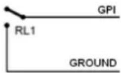
• Setup "1 of 4" (use 1% resistors)

text_image
R2, 22k RL2 3V3 R3, 11k GPI R1, 12k RL1 GROUND- Setup "1 of 8" (use 1% resistors)
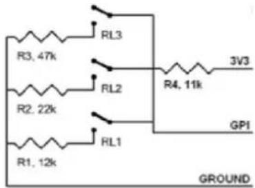
text_image
R3, 47k R2, 22k R1, 12k RL3 RL2 RL1 R4, 11k 3V3 GPI GROUND
GPI Voltage Windows
In the table below, voltages outside the limits mentioned are to be considered invalid. No action is taken if invalid measurements are made. GPI recall action resumes when a stable, valid measurement is detected again.
| Mode | User Preset No | Scaled Target /Vs | Min typ /V | Target typ /V | Max typ /V | RL3 RL2 RL1 | ||
| 1 of 2 1 | 1.000 (idle) | 2.67 3.30 | 3.30 open | |||||
| 2 | 0.000 | 0.00 | 0.00 | 0.51 | closed | |||
| 1 of 4 1 | 1.000 (idle) | 3.20 3.30 | 3.30 open | open | ||||
| 2 | 0.689 | 2.18 | 2.28 | 2.38 | closed | open | ||
| 3 | 0.548 | 1.71 | 1.81 | 1.91 | open | closed | ||
| 4 | 0.439 | 0.00 | 1.45 | 1.55 | closed | closed | ||
| 1 of 8 1 | 1.000 (idle) | 3.20 3.30 | 3.30 open | open open | ||||
| 2 | 0.826 | 2.63 | 2.73 | 2.83 | closed | open | open | |
| 3 | 0.689 | 2.18 | 2.28 | 2.38 | open | closed | open | |
| 4 | 0.602 | 1.93 | 1.99 | 2.05 | closed | closed | open | |
| 5 | 0.548 | 1.75 | 1.81 | 1.87 | open | open | closed | |
| 6 | 0.491 | 1.56 | 1.62 | 1.68 | closed | open | closed | |
| 7 | 0.439 | 1.40 | 1.45 | 1.50 | open | closed | closed | |
| 8 | 0.402 | 0.00 | 1.33 | 1.38 | closed | closed | closed | |
Notes:
- "Idle" refers to the state when no input is connected, or when the input is left floating.
- Rather than absolute voltage measurements, the windows are defined as a fraction of the supply voltage. This voltage can be measured with a high impedance DMM on the D-SUB pin 5 or 10.
- The table shows values as a fraction of the supply voltage, and, as a guideline, typical voltages when the supply is 3.30 V. (If the supply voltage is for example 3.315 V, the table should be corrected by multiplying these values by 3.315/3.3).
18. Acoustics Enhancement
The Reverb TwentyFour features a high degree of de-correlation between the reverb channels, in addition to the amazing sonic detail and flexibility of its first-class algorithm. This makes the Reverb TwentyFour an excellent choice for changing the acoustics in a multi-purpose venue.
Here are some typical venues where you might use the Reverb TwentyFour to electrically change the acoustics to suit the performance type:
House of Worship – Here the acoustics can be changed to suit various aspects of church life and services, such as concerts of various genres, singing, choir music, in addition to the spoken word and readings. Wooden churches and small chapels can benefit by sounding more like classical stone churches and for concerts, performances and speech.
Concert Halls – Those that are intended for a wide variety of uses, such as rock, theatre, jazz, opera, and classical music.
Outdoor Concerts – Here you may want to add the sound of a concert hall for example, or other acoustical enhancements in an outdoor environment.
Museums – Here you can add all sorts of sound changes to the exhibit environment, and enhance the museum experience for visitors.
Cruise Ships – Here the acoustics can be changed to suit a wide range of indoor and on-deck entertainment including song, dance, concerts, lectures, children's shows, and musicals.
Acoustics Enhancement Presets
The Reverb TwentyFour supports acoustics enhancement with a Presets group called "F5: Acoustics, RT60." This group contains 6 presets for different decay times: 0.6, 0.8, 1.2, 1.8, 2.2 and 2.7 sec RT60. (RT60 is the time it takes for the sound to decay by 60 dB after the sound source stops).

text_image
Reverb TwentyFour Library Frame E1 E2 E3 Recall Scans Routing E1 Delete Bank Factory User F1: Unwrap 24 Channels F2: Unwrap 16 Channels F3: Film 24 Ch. In/Out F4: Film 3 x Surround F5: Acoustics, RT60 Recall Scans Reset Store Delete Bank Acoustics 1.8 sec Acoustics 0.6 sec 1 Acoustics 0.6 sec 2x24, Side columns, Ceiling rows 1-4 2 Acoustics 0.8 sec 2x24, Side columns, Ceiling rows 1-4 3 Acoustics 1.2 sec 2x24, Side columns, Ceiling rows 1-4 4 Acoustics 1.8 sec 2x24, Side columns, Ceiling rows 1-4 5 Acoustics 2.2 sec 3x24, Side columns, Ceiling rows 1-4 6 Acoustics 2.7 sec 2x24, Side columns, Ceiling rows 1-4As an example, using the Reverb TwentyFour, you may be able to extend the decay time (RT60) of a venue by a factor of 2 from its original time.
The reverb field made by the Reverb TwentyFour and received at the audience seats, is extremely even and it is difficult to point out the individual speakers. The lack of any comb-filtering and phasing issues between the reverbing speakers also results in maximum headroom before there is any acoustical feedback to the stage microphones. This gives the opportunity to use less-directive microphones over the stage.
A Typical Acoustics Enhancement System
- The audience receives the direct sound from the performance either acoustically or through a PA system.
- The audience receives the reverb field from reverb speakers mounted above, behind, and to the sides of the audience, as shown in the diagram below.

flowchart
graph TD
    subgraph Engine_1
        A["7"] --> B["5"]
        B --> C["3"]
        C --> D["1"]
        D --> E["PA"]
    end

    subgraph Engine_2
        F["13"] --> G["9"]
        G --> H["PA"]
    end

    subgraph Engine_3
        I["17"] --> J["18"]
        J --> K["19"]
        K --> L["20"]
        L --> M["8"]
        M --> N["6"]
        N --> O["4"]
        O --> P["PA"]
    end

    style Engine_1 fill:#f9f,stroke:#333
    style Engine_2 fill:#f9f,stroke:#333
    style Engine_3 fill:#f9f,stroke:#333

    note right of F: Group 2 Group 1
    note right of G: Group 2 Group 1
    note right of H: Group 2 Group 1
    note right of L: Group 2 Group 1
    note right of M: Mics
    note right of P: PA
    note right of Q: 2.4 m
    note right of R: 4 m
Numbers = MADI channels
Speaker 7 and 8 are optional
Microphones are wide cardoid type e.g. DPA 4015
Ceiling speakers
Speakers at ear height
- An acoustics enhancement system used in a multi-purpose venue, often consists of the following:
- Microphones picking up the sound signals over the stage. (For example, a wide cardoid type such as the 4015 manufactured by DPA Microphones).
• Good-quality microphone preamplifiers. - The use of soft multi-band compression can give great results when added to the chain.
• MADI equipment to convert to and from MADI. - The signals are sent via MADI to the Reverb TwentyFour and from there, MADI out to the multi-channel amplification system and the individual speakers – one per reverb channel.
- By using two Reverb TwentyFour units, up to 48 fully de-correlated channels are possible.
Assumptions for an Acoustics Enhancement System
• All reverb speakers are calibrated to play identical levels.
• The speakers should be able to reproduce signals well down to 100 Hz.
- The input to the system is stereo. Different input routing in the Reverb TwentyFour can accommodate input formats such as 5.1 and 7.1.
• All reverb speakers are playing the reverb 100% wet.
- The speakers are mounted in the venue ceiling and at the sides and rear of the venue at ear height. The distance between the speakers is often between 3 to 6 meters, but it depends on the distance from the audience to the speakers.

The Reverb Preset Settings:
- Reverb level is important and it should be adjusted individually for each installation. There is a fine balance between "hearing" the reverb and making it "fit" the venue and music genre.
- Engine 1 (E1) handles the side speakers, E2 handles the 2 rows of ceiling speakers closest to the stage, and E3 handles the rear 2 rows (see the speaker layout diagram on page 45).
- Using the Frame - E1-3 page, the Output Level parameter can be used for fast adjustment of the audience speaker level. Use the Mute button to switch the reverb off for comparison (it turns off the Wet signals only).
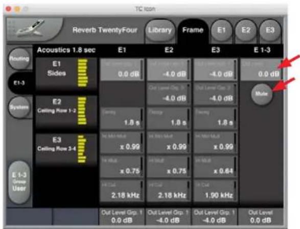
text_image
TC Icon Reverb TwentyFour Library Frame E1 E2 E3 Acoustics 1.8 sec E1 E2 E3 E 1-3 Routing E1 Sides 0.0 dB -4.0 dB -4.0 dB 0.0 dB E1-3 System E2 Ceiling Row 1-2 Out Level Grp. 3 -4.0 dB Out Level Grp. 3 -4.0 dB Multi E3 Ceiling Row 3-4 Tuning 1.8 s Frequency 1.8 s Frequency 1.8 s No Mio/Hz x 0.99 x 0.99 x 0.99 x 0.99 x 0.75 x 0.75 x 0.64 In Out Level Grp. 1 0.0 dB In Out Level Grp. 1 -4.0 dB In Out Level Grp. 1 -4.0 dB Out Level Grp. 1 0.0 dB- The Frame - E1-3 page shows a fast overview of each engine. The parameters shown here are chosen in each engine so you have fast access to the most commonly used parameters in an acoustics controlling installation.
- Trim delays are adjusted for all speakers to compensate for the physical distance from PA front to the 4 speaker rows.
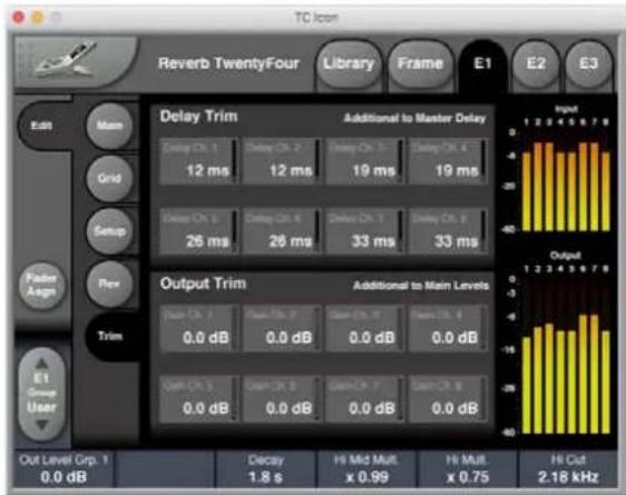
text_image
TC Icon Reverb TwentyFour Library Frame E1 E2 E3 Edit Main Grid Setup Flow Poster Assign Trim E1 Group Ch. 1 Delay Ch. 1 12 ms Delay Ch. 2 12 ms Delay Ch. 3 19 ms Delay Ch. 4 Delay Ch. 5 26 ms Delay Ch. 6 26 ms Delay Ch. 7 33 ms Delay Ch. 8 33 ms Delay Ch. 9 Delay Ch. 10 Delay Ch. 11 Delay Ch. 12 Delay Ch. 13 Delay Ch. 14 Delay Ch. 15 Delay Ch. 16 Delay Ch. 17 Delay Ch. 18 Delay Ch. 19 Delay Ch. 20 Delay Ch. 21 Delay Ch. 22 Delay Ch. 23 Delay Ch. 24 Delay Ch. 25 Delay Ch. 26 Delay Ch. 27 Delay Ch. 28 Delay Ch. 29 Delay Ch. 30 Delay Ch. 31 Delay Ch. 32 Delay Ch. 33 Delay Ch. 34 Delay Ch. 35 Delay Ch. 36 Delay Ch. 37 Delay Ch. 38 Delay Ch. 39 Delay Ch. 40 Delay Ch. 41 Delay Ch. 42 Delay Ch. 43 Delay Ch. 44 Delay Ch. 45 Delay Ch. 46 Delay Ch. 47 Delay Ch. 48 Delay Ch. 49 Delay Ch. 50 Delay Ch. 51 Delay Ch. 52 Delay Ch. 53 Delay Ch. 54 Delay Ch. 55 Delay Ch. 56 Delay Ch. 57 Delay Ch. 58 Delay Ch. 59 Delay Ch. 60 Delay Ch. 61 Delay Ch. 62 Delay Ch. 63 Delay Ch. 64 Delay Ch. 65 Delay Ch. 66 Delay Ch. 67 Delay Ch. 68 Delay Ch. 69 Delay Ch. 70 Delay Ch. 71 Delay Ch. 72 Delay Ch. 73 Delay Ch. 74 Delay Ch. 75 Delay Ch. 76 Delay Ch. 77 Delay Ch. 78 Delay Ch. 79 Delay Ch. 80 Delay Ch. 81 Delay Ch. 82 Delay Ch. 83 Delay Ch. 84 Delay Ch. 85 Delay Ch. 86 Delay Ch. 87 Delay Ch. 88 Delay Ch. 89 Delay Ch. 90 Delay Ch. 91 Delay Ch. 92 Delay Ch. 93 Delay Ch. 94 Delay Ch. 95 Delay Ch. 96 Delay Ch. 97 Delay Ch. 98 Delay Ch. 99 Delay Ch. 100 Delay Trim Additional to Master Delay Output Trim Additional to Main Levels Out Level Grp. 1: 0.0 dB Decay Hi Mid Mult. x 0.99 Hi Mult. x 0.75 Hi Cut 2.18 kHz- Predelay is not included in the factory presets, but may be added to include the Haas effect, for example 20 ms. This could enhance the details coming directly from the stage and give the ability to increase the overall reverb level without muddying the sound image.
• Ceiling speakers are reduced by 4 dB to help prevent a "reverb raining effect." - Row 3 and 4 (including the side speakers) are adjusted for slightly shorter Hi-frequency decay time and lower Hi-Cut, to create a slightly darker-sounding rear venue.
- The overall reverb sound and coloring is carefully tuned in existing venue installations where different decay time for classical music (typically 2.2s), opera and piano (typically 1.8s), bigband and jazz (typically 1.2s), 0.8 and
2.7s are included. The sound of the venue itself, the microphones picking up the sound over the stage, plus the speakers themselves, makes a difference to the combined sound of the system. Therefore, individual system and reverb adjustments may be needed to make the reverb "fit" the venue.
- In order to ensure maximum de-correlation of the audience speakers, use the E1, E2, and E3 - REV pages and adjust the No of Channels and Assignment parameters so they are set differently in all 3 engines.
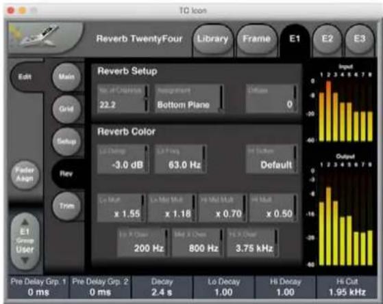
text_image
TC Icon Reverb TwentyFour Library Frame E1 E2 E3 Edit Main Grid Setup Fader Assign Rev Trim E1 Group User Reverb Setup No. of Chirchek 22.2 Reverb Color Lo Change -3.0 dB Lo Parg 63.0 Hz Default Lo Mut x 1.55 Lo Mio Mut x 1.18 Lo Mio Mut x 0.70 Lo Mut x 0.50 Lo X Clos 200 Hz 800 Hz 3.75 kHz Input Output Pre Delay Grp. 1 0 ms Pre Delay Grp. 2 0 ms Decay 2.4 s Lo Decay 1.00 Hi Decay 1.00 Hi Cut 1.95 kHz- Note: the E1, E2, and E3 engines have "Bottom," "Mid," and "Top" settings respectively, in order to have the de-correlation set to "max". This may not fully reflect the physical setup, as this will vary between venues, and so other settings for the "No of Channels" may be better in some cases.
- This means that the reverb field at the audience seats is extremely even and it's difficult to point out the individual speakers. As mentioned before, the lack of any comb filtering and phasing issues between the reverbing speakers also results in maximum headroom before acoustical feedback to the stage microphones, which also gives the ability to use less directive microphones over the stage.
- The stereo inputs are randomly but statically routed across the 24 reverb channel inputs. This is done to ensure there is an even reverb field, with very little Left/Right-specific information at the audience seats. Different input routing in the Reverb TwentyFour can also accommodate input formats such as 5.1 and 7.1.
- A venue might not always be full at every show. Therefore it may be a good idea to make more presets for a full venue, and a 2/3-full venue etc. The rear speakers could be turned down or off with a 2/3-full venue, and the decay time could also be set shorter, and the coloring set a bit darker in this case.
General Notes About Changing Acoustics
- As a rule of thumb, you may be able to extend/prolong the decay time of a venue by a factor of 2 from its original time using the Reverb TwentyFour.
- An A-B microphone setup using wide cardioid microphones like the DPA 4015 is a good solution for picking up stage sound.
- Often you may need to introduce a multiband compressor with soft settings prior to the reverb channels, to catch fast transients from the stage that may sound slightly artificial by the time they reach the audience.
GPI Control
- The GPI input of the Reverb TwentyFour may be used to select the preset so it does not take a highly-educated engineer to set up the suitable decay time for a specific show. A custom made push-button GPI box may be made for the specific installation to easily change the presets.
19. Specifications
General
| Frame Configuration | MADI I/O |
| Front Indicators/Control | Status LED: Runnnig, Net, Bypassed and Sync. IP address reset button |
| Finish | Black anodized aluminum face plate Plated steel chassis |
| Dimensions | 19 x 1.75 x 13.2 inches(483 x 44 x 334 mm), 1 RU |
| Weight | 8.4 lbs. (3.8 kg) |
| Mains Voltage | 100 to 240 VAC, 50 to 60 Hz auto-select |
| Fan | High quality fan |
| Power Consumption | 7 W typ |
| Warranty, Parts and Labor | 3 Years |
EMC
| Complies with | EN 55103-1 and EN 55103-2, FCC part 15 class B, CISPR 22 class B |
Safety
| Certified to IEC 60065, EN 60065, UL 6500 and CSA E65 |
Environment
| Operating Temperature | 32°F to 122°F (0°C to 50°C) |
| Storage Temperature | -22°F to 167°F (-30°C to 70°C) |
| Humidity | Max. 90% non-condensing |
Control interface
| Ethernet and TC Icon Rmt Control | 2 ports, RJ45, 10/100 Mbits/s, Base-T, SNMP-enabled |
| GPI, control inputs (D-SUB) | Multi-state for preset recall. 0 V to 3.3 V DC sensing |
| GPO, output voltage (D-SUB) | 3.3 V DC, 100 mA current limited |
General Processing
| Input Audio Format From one channel to 24 channels |
| Output Audio Format From one channel to 24 channels, as long as the number of output channels is greater than the number of input channels (Reverb TwentyFour can not downmix) |
| Number of Reverb Engines 3 |
| Number Audio Channels Processed 24 |
| Unused Output Channels Bypassed from respective input channels |
| Audio Processing Delay 41 samples, 2.08 ms @ 48 kHz (digital in to digital out) |
| Frequency Response DIO DC to 23.9 kHz +/- 0.01 dB |
| Audio Processing Resolution 40 bit precision, bit transparent |
| Internal Clock Precision +/- 30 PPM |
| External Sample Rates 48 kHz +/-1.5 % |
| Interface Function Synchronous, bit transparent |
| Digital IO Engine TC developed DICETM core |
MADI
| Connectors 1 BNC In, 1 BNC Out. 75 Ohm | |
| Function | Audio input and MADI through/output |
| Number of channels | 28, 32, 56, 64 in |
| Sample Rate | 48 kHz |
| Complies with Standards | AES10-2008 r2014 |
| Digital Output Phase | < 2 % of sample period |
| Input Signal Tolerance | Complies to AES10-2008 r2014 |
| Output Signal Level Complies to AES10-2008 r2014 | |
Legal Disclaimer
MUSIC Group accepts no liability for any loss which may be suffered by any person who relies either wholly or in part upon any description, photograph, or statement contained herein. Technical specifications, appearances and other information are subject to change without notice.

FEDERAL COMMUNICATIONS COMMISSION COMPLIANCE INFORMATION


tc electronic
REVERB TWENTYFOUR
Responsible Party Name: Music Group Services NV Inc.
Address: 5270 Procyon Street
Las Vegas, NV 89118
USA
Phone Number: +1 702 800 8290
REVERB TWENTYFOUR
EMC/EMI This equipment has been tested and found to comply with the limits for a Class B Digital device, pursuant to part 15 of the FCC rules. These limits are designed to provide reasonable protection against harmful interference in residential installations.
This equipment generates, uses and can radiate radio frequency energy and, if not installed and used in accordance with the instructions, may cause harmful interference to radio communications. However, there is no guarantee that interference will not occur in a particular installation. If this equipment does cause harmful interference to radio or television reception, which can be determined by turning the equipment off and on, the user is encouraged to try to correct the interference by one or more of the following measures:
• Reorient or relocate the receiving antenna.
- Increase the separation between the equipment and receiver.
- Connect the equipment into an outlet on a circuit different from that to which the receiver is connected.
- Consult the dealer or an experienced radio/ TV technician for help.
For customers in Canada This Class B digital apparatus complies with Canadian CAN ICES-3B.