Downdraft - Basket Airforce - Free user manual and instructions
Find the device manual for free Downdraft Airforce in PDF.

| Brand | Airforce |
| Model | Downdraft |
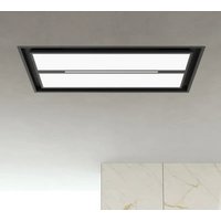
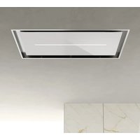
| Product type | Integrated downdraft extractor / filter hood |
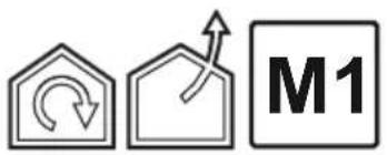
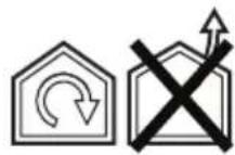
| Usage version | Extractor version (external evacuation) or filter version (recirculation with charcoal filter) |
| Dimensions (W x D x H) | Approximately 750-900 mm x 500 mm x 200 mm (depending on cabinet configuration) |
| Net weight | Approximately 15 kg |
| Power supply | 220-240 V ~ 50/60 Hz |
| Suction power | 3 speeds + 2 Boost levels (Boost 1: 30 min, Boost 2: 7 min) |
| Lighting | Integrated LED, variable intensity by long press on T1 button |
| Controls | Touch control panel with control screen A (panel open/close) and screen B (speed, lighting, indicators) |
| Filters | Washable metal grease filter (monthly); washable activated charcoal filter (every 2 months, replacement every 3 years) |
| Filter saturation indicator | Flashing L1 lights: together for grease filter, alternately for charcoal filter |
| Safety | Safety switches inhibiting operation if front panel is detached; automatic shutdown in case of overheating (via circuit breaker) |
| Installation | Minimum distance of 400 mm between the hob and components above; electronic box at least 65 cm from the hob |
| Maintenance and cleaning | Monthly cleaning of the exterior with a damp cloth and neutral detergent; do not use alcohol or abrasives |
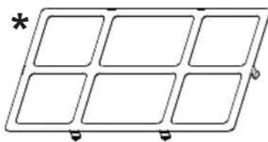
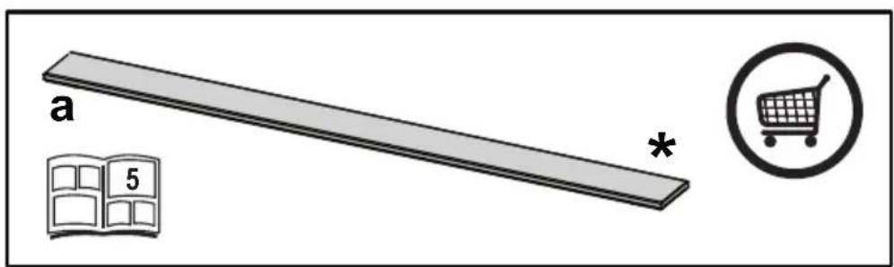
| Spare parts | Parts marked (*) optional; replace LED lamps only by authorized service |
| Repairability | Repair by authorized service center; do not cut the motor connection cable (warranty void) |
| Environmental information | End of life recycling: do not dispose with household waste (WEEE) |
Frequently Asked Questions - Downdraft Airforce
User questions about Downdraft Airforce
0 question about this device. Answer the ones you know or ask your own.
Ask a new question about this device
Download the instructions for your Basket in PDF format for free! Find your manual Downdraft - Airforce and take your electronic device back in hand. On this page are published all the documents necessary for the use of your device. Downdraft by Airforce.
USER MANUAL Downdraft Airforce
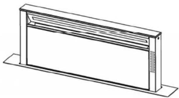
EN Instruction on mounting and use
natural_image
Simple line drawing of a rectangular object with a recessed inner section and a small textured base (no text or symbols)natural_image
Line drawing of a rectangular metal enclosure or enclosure with a recessed top panel (no text or symbols)T1. Tasto luce ON/OFF
EN - Instruction on mounting and use
Closely follow the instructions set out in this manual. All responsibility, for any eventual inconveniences, damages or fires caused by not complying with the instructions in this manual, is declined. This appliance is intended to be used in household and similar application such as: - staff kitchen areas in shop, offices and other working environments; - farm houses; - by clients in hotels, motels and other residential type environments; - bed and breakfast type environments.
The hood can look different to that illustrated in the drawings in this booklet. The instructions for use, maintenance and installation, however, remain the same.
- It is important to conserve this booklet for consultation at any moment. In the case of sale, cession or move, make sure it is together with the product.
- Read the instructions carefully: there is important information about installation, use and safety.
- Do not carry out electrical or mechanical variations on the product or on the discharge conduits.
- Before proceeding with the installation of the appliance verify that there are no damaged all components. Otherwise contact your dealer and do not proceed with the installation.
Note: The parts marked with the symbol "(*)" are optional accessories supplied only with some models or otherwise not supplied, but available for purchase.

Caution
- Before any cleaning or maintenance operation, disconnect hood from the mains by removing the plug or disconnecting the mains electrical supply.
• Always wear work gloves for all installation and maintenance operations. - This appliance can be used by children aged from 8 years and above and persons with reduced physical, sensory or mental capabilities or lack of experience and knowledge if they have been given supervision or instruction concerning use of the appliance in a safe way and understand the hazards involved.
- Children shall not be allowed to tamper with the controls or play with the appliance.
- Cleaning and user maintenance shall not be made by children without supervision.
• The premises where the appliance is
installed must be sufficiently ventilated, when the kitchen hood is used together with other gas combustion devices or other fuels.
- The hood must be regularly cleaned on both the inside and outside (AT LEAST ONCE A MONTH).
- This must be completed in accordance with the maintenance instructions provided. Failure to follow the instructions provided regarding the cleaning of the hood and filters will lead to the risk of fires.
- Do not flambé under the range hood.
- Do not remove filters during cooking.
- For lamp replacement use only lamp type indicated in the Maintenance/Replacing lamps section of this manual.
The use of exposed flames is detrimental to the filters and may cause a fire risk, and must therefore be avoided in all circumstances.
Any frying must be done with care in order to make sure that the oil does not overheat and ignite.
CAUTION: Accessible parts of the hood may become hot when used with cooking appliances.
- Do not connect the appliance to the mains until the installation is fully complete.
- With regards to the technical and safety measures to be adopted for fume discharging it is important to closely follow the regulations provided by the local authorities.
- The air must not be discharged into a flue that is used for exhausting fumes from appliance burning gas or other fuels.
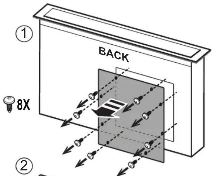
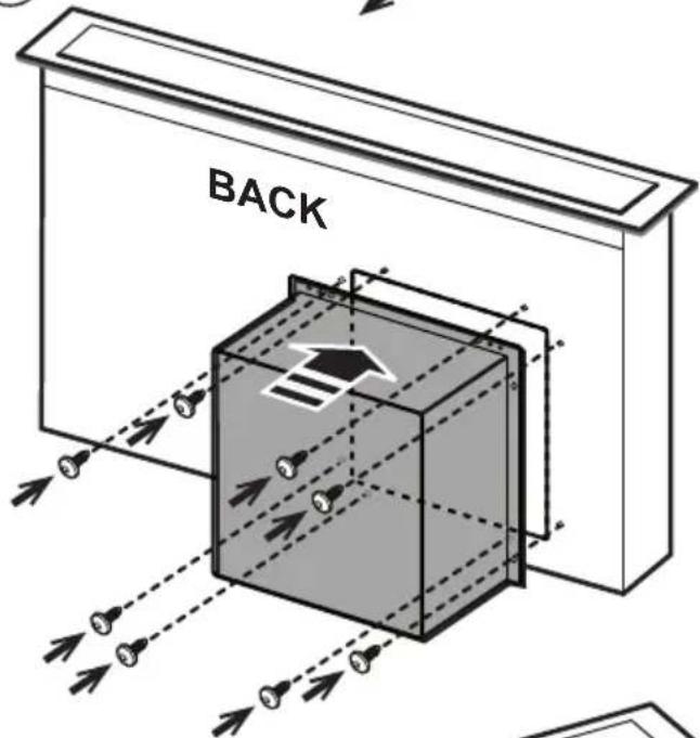
⚠ WARNING! Failure to install the screws or fixing device in accordance with these instructions may result in electrical hazards.
- Do not use or leave the hood without the lamp correctly mounted due to the possible risk of electric shocks.
- Never use the hood without effectively mounted grids.
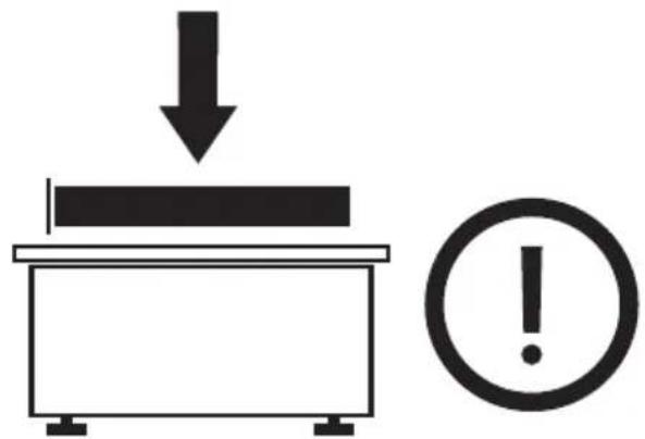
- The hood must NEVER be used as a support surface unless specifically indicated.
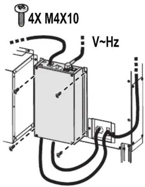
- Use only the fixing screws supplied with the product for installation or, if not supplied, purchase the correct screws type.
- Use the correct length for the screws which are identified in the Installation Guide.
- In case of doubt, consult an authorized service assistance center or similar qualified person.
⚠ WARNING! Do not use with a programmer, timer, separate remote control system or any other device that switches on automatically.
Electrical connection
The hood must be connected to the mains supply by qualified and trained technicians.
The mains power supply must correspond to the rating indicated on the plate situated inside the hood. If provided with a plug connect the hood to a socket in compliance with current regulations and positioned in an accessible area, after installation. If it not fitted with a plug (direct mains connection) or if the plug is not located in an accessible area, after installation, apply a double pole switch in accordance with standards which assures the complete disconnection of the mains under conditions relating to over-current category III, in accordance with installation instructions.
⚠ WARNING! Before re-connecting the hood circuit to the mains supply and checking the efficient function, always check that the mains cable is correctly assembled.
Installation
If the instructions for installation for the gas hob specify a greater distance, this must be adhered to.
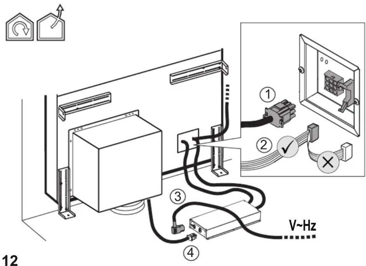
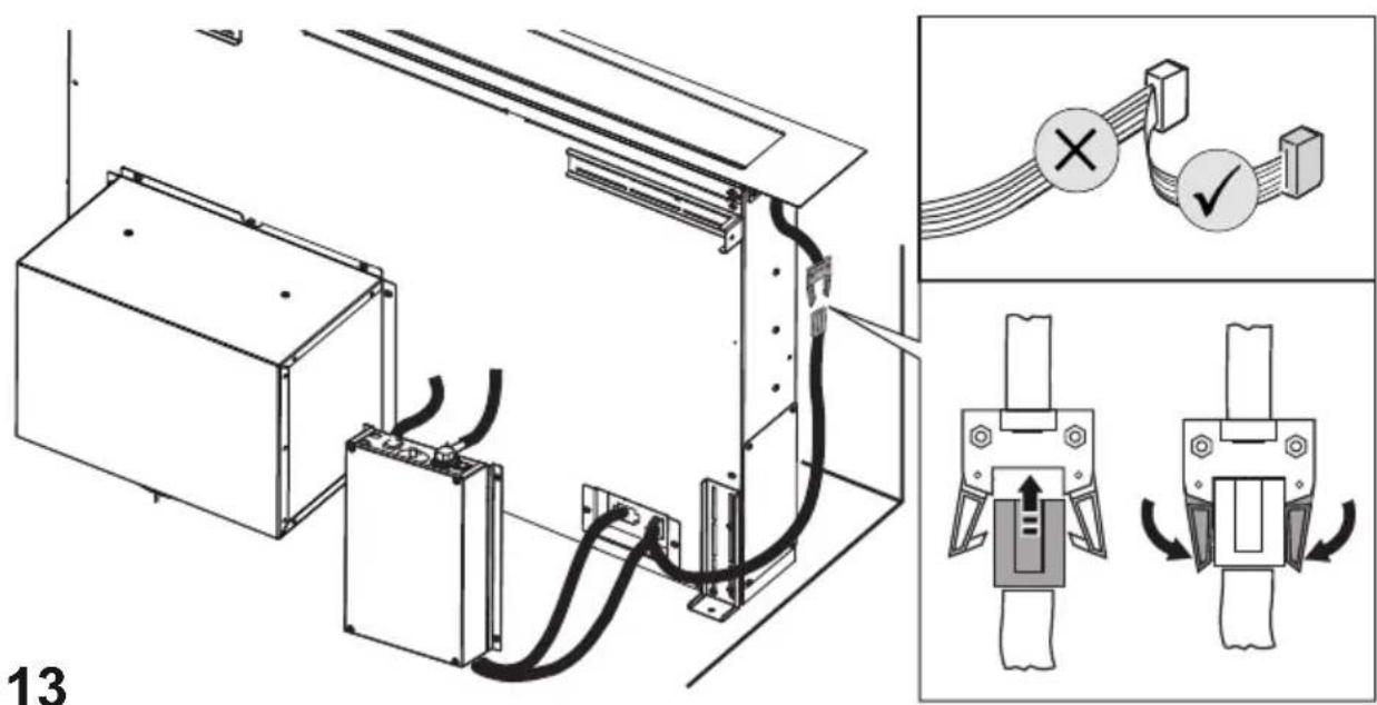
Note: The installation must be performed so that accessibility to the hood and its electronic components is always ensured for possible technical assistance interventions.
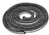
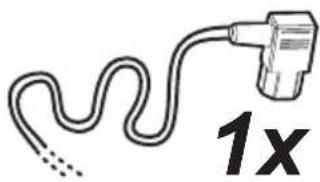
Note: the cable that connects the remote motor to the hood is 3 metres long
Caution! Do not cut the cable between the hood and the engine to avoid losing your right to warranty!
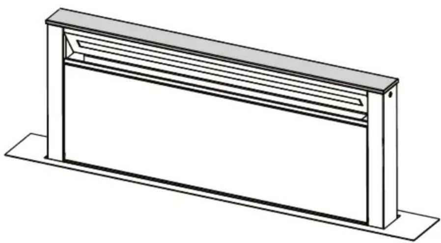
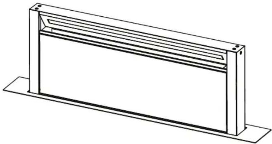
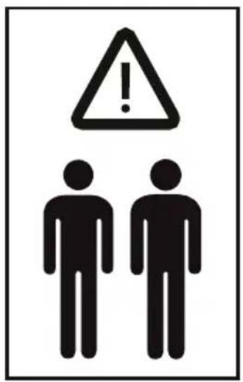
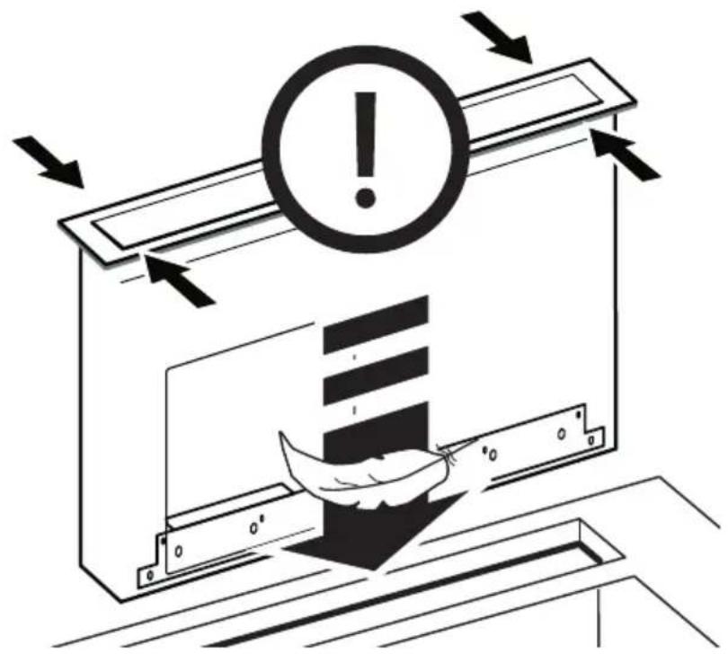
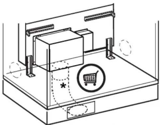
When handling the hood do not put hands within the range of action of the pull-out suction panel (trolley)
The hood is equipped with safety switches which inhibit operation when the front filter panel is unhooked.
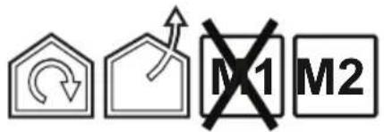
With the intention of constantly improving our products, we reserve the right to make all the changes in their technical, functional or design characteristics, deriving from their evolution. In case of the version with external motor, the normal operation of the hood requires the use of a suction unit (external motor) of the same manufacturer.
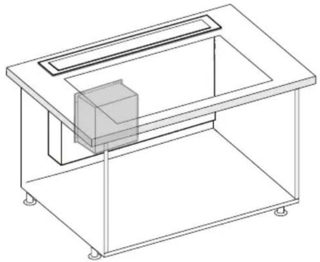
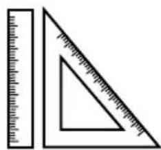
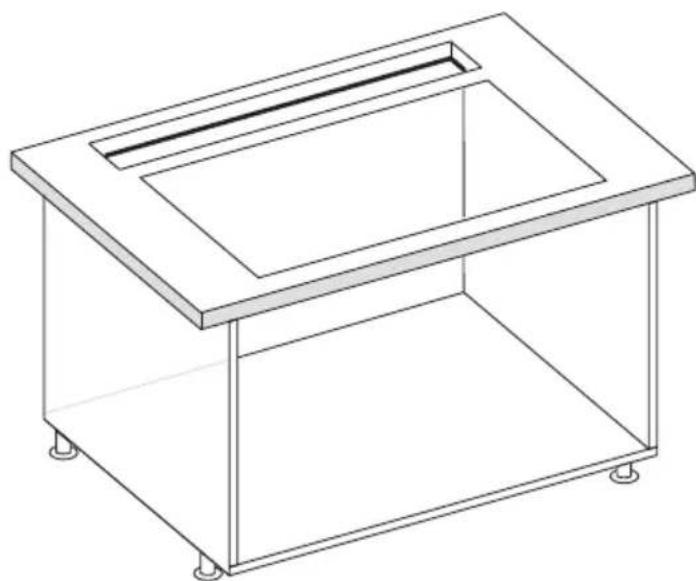
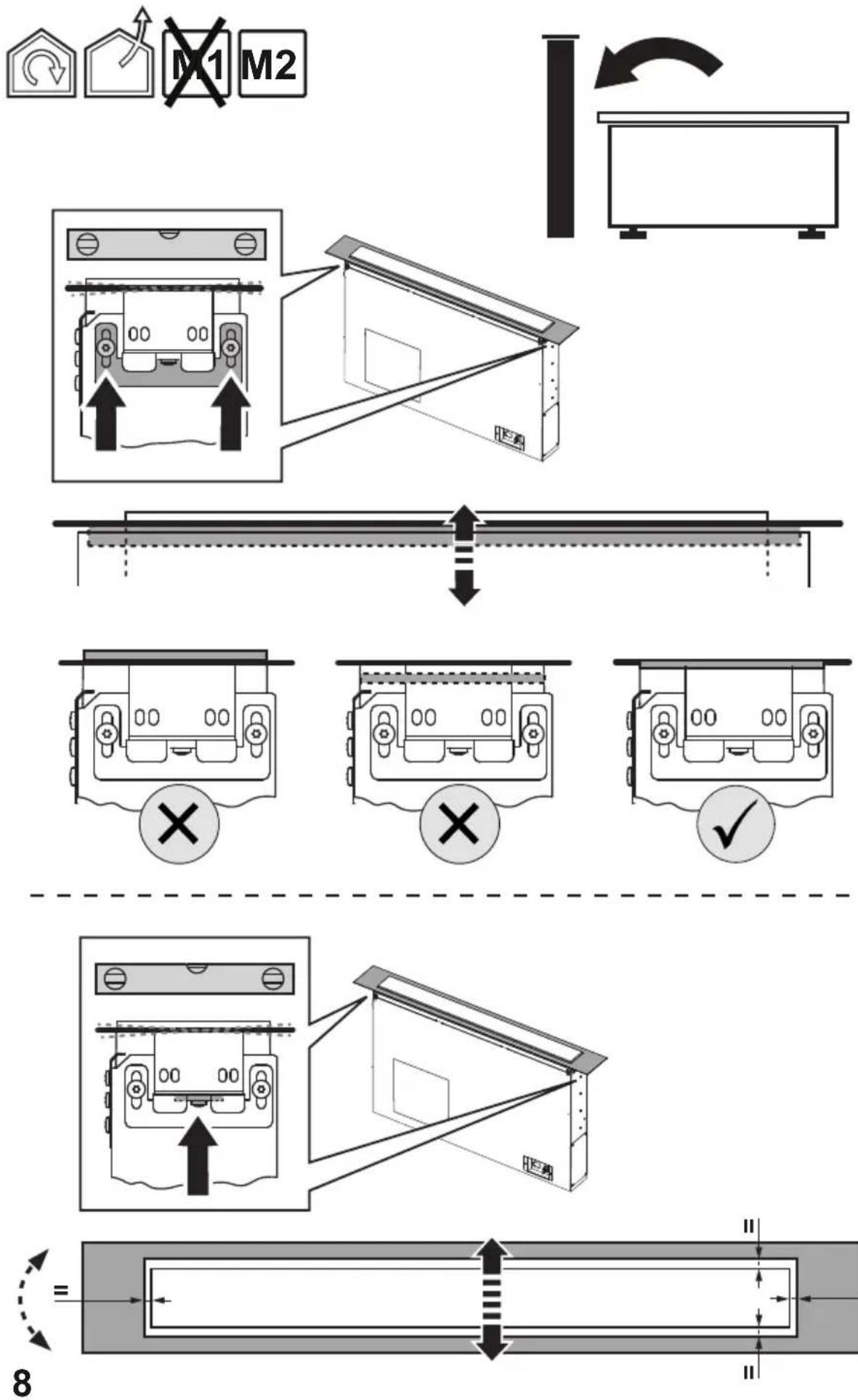
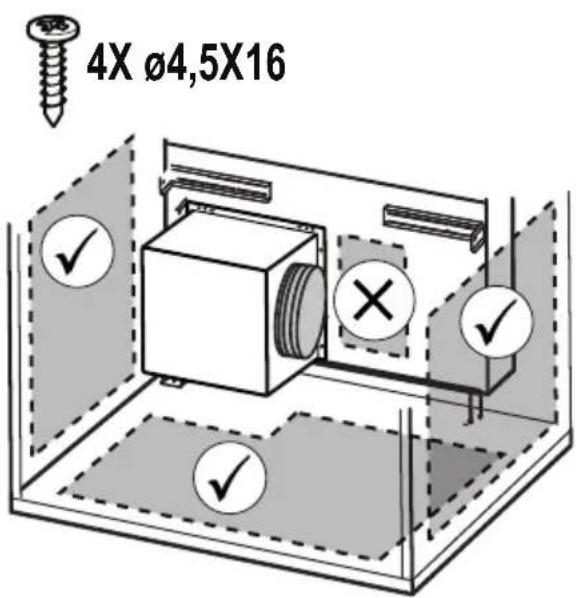
When installing the product, it is recommended to keep a minimum distance of 400mm between the worktop and any components laid on top of the hood.
This is to let the suction panel move upwards (opening) and downwards (closing) without any obstacles, and to facilitate access to the hood controls on the panel.
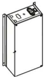
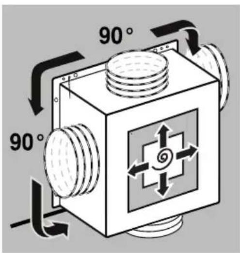
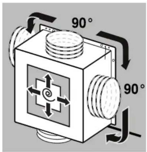
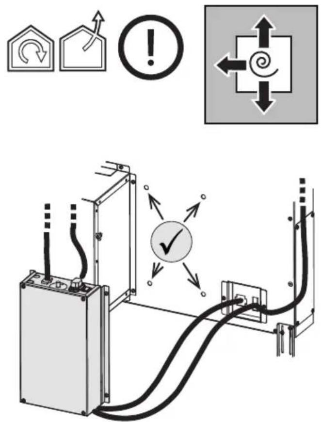
WARNING: Put the metal box containing the electronic components at a distance not shorter than 65 cm from the gas hob or 65 cm from the hood suction point.
RECOMMENDATION: We recommend you to install the metal box containing the electronic components at a distance of at least 10 cm from the ground and sufficiently from all the sources of heat (e.g.: side of an oven or hob).
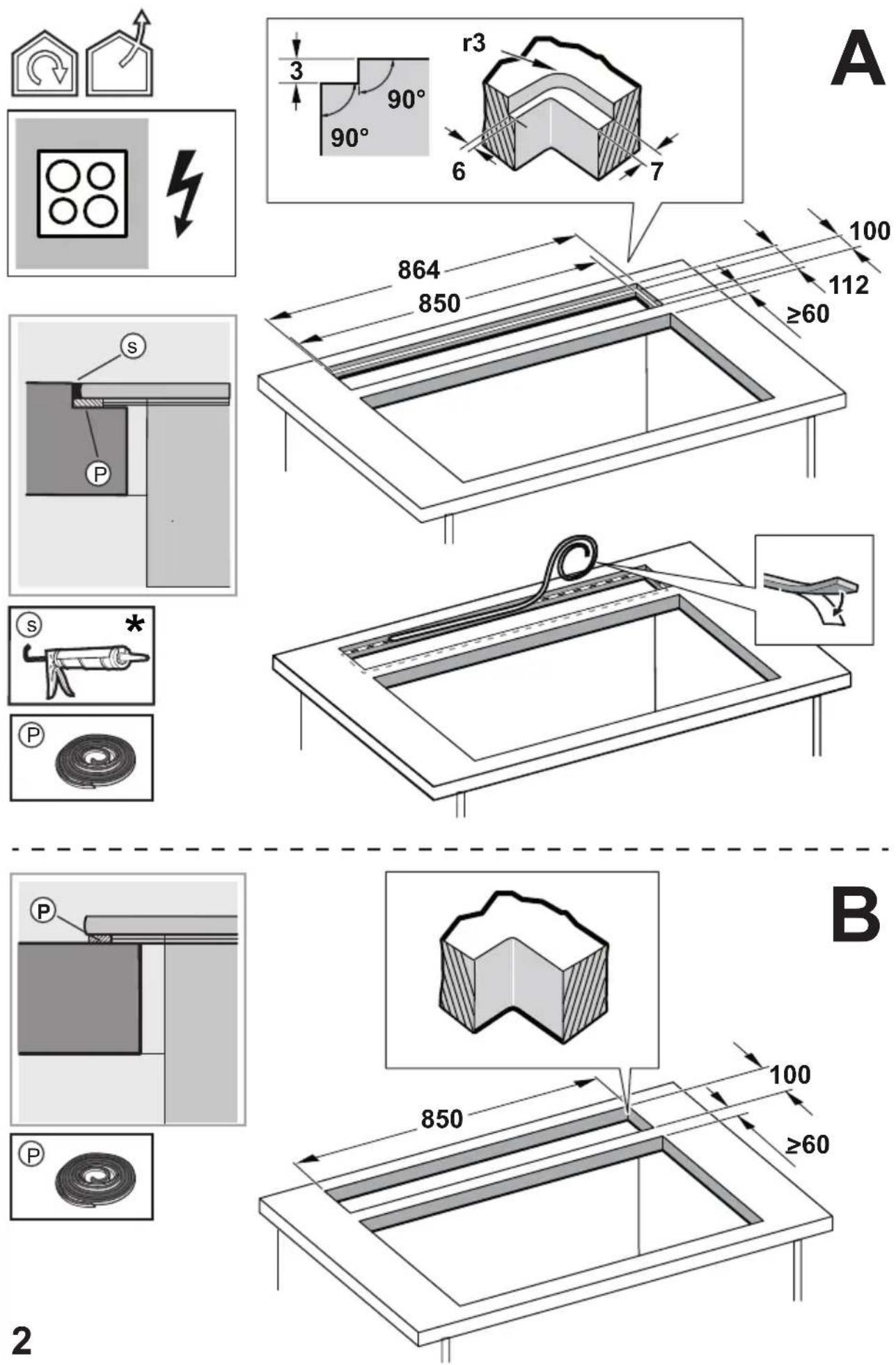
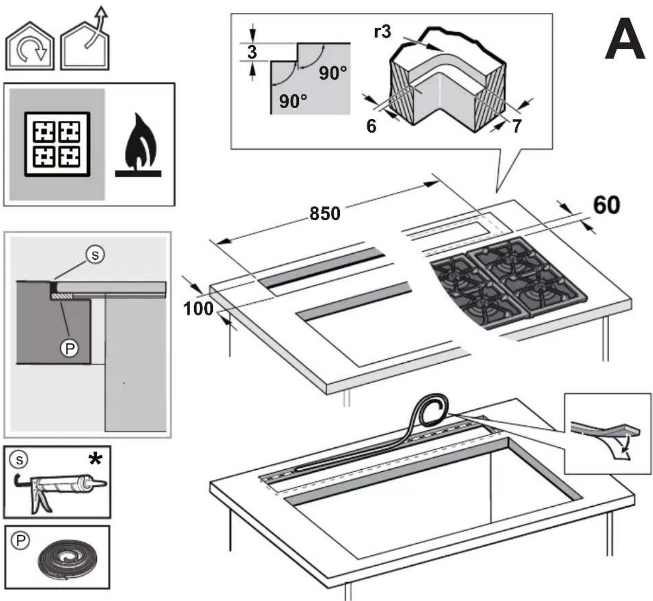
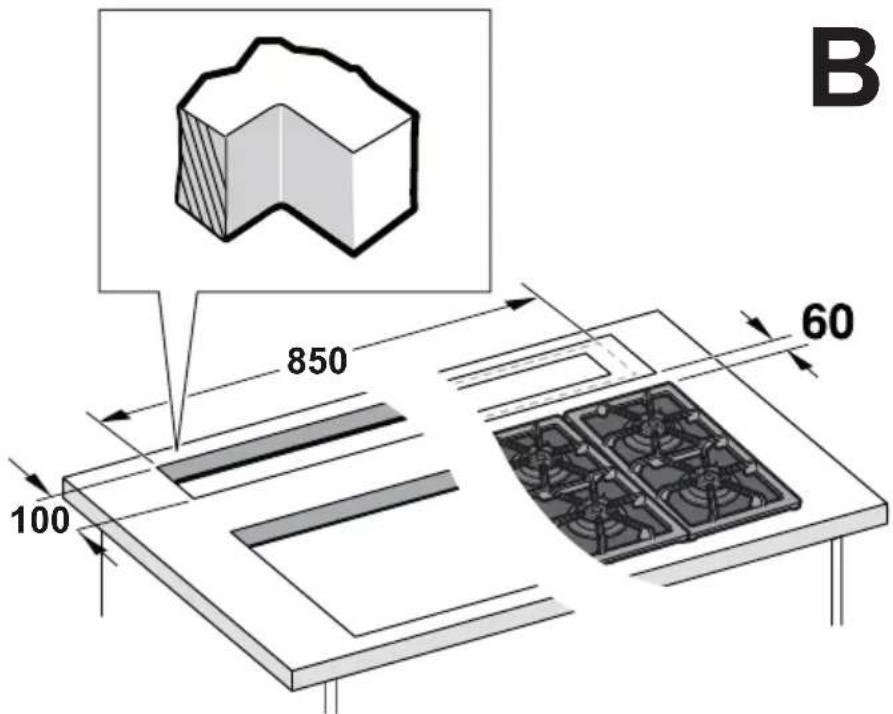
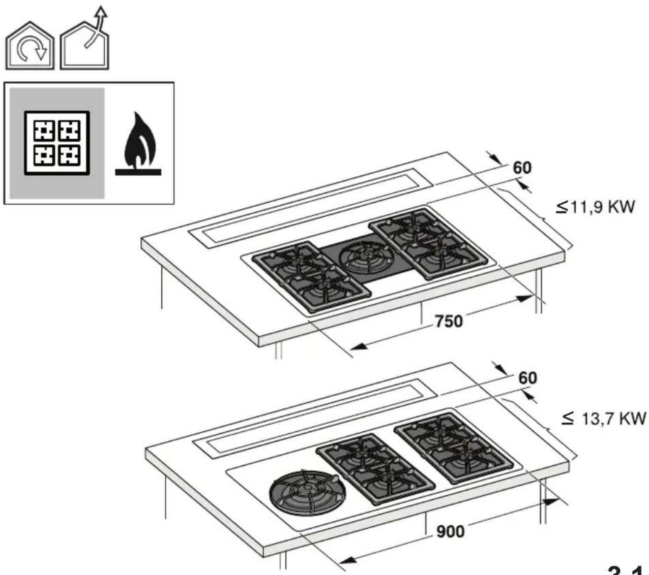
GAS COOKTOP:
All gas cooktops must not exceed the following values: Maximum total power as in fig.3 and max 5 single burners. ● A 75cm gas cooktop must not exceed the following values: Maximum total power 11.9 KW; maximum total power of rear hobs: 4.7 KW; maximum power of wok 4.2 KW. ● A 90 cm gas cooktop must not exceed the following values: Maximum total power 13.7 KW; maximum total power of rear hobs: 4.7 KW; maximum power of wok 6 KW.
- This appliance is marked according to the European directive 2012/19/EC - UK SI 2013 No.3113 on Waste Electrical and Electronic Equipment (WEEE).
- By ensuring this product is disposed of correctly, you will help prevent potential negative consequences for the environment and human health, which could otherwise be caused by inappropriate waste handling of this product.
- The symbol ■ on the product, or on the documents accompanying the product, indicates that this appliance may not be treated as household waste. Instead it should be taken to the appropriate collection point for the recycling of electrical and electronic equipment. Disposal must be carried out in accordance with local environmental regulations for waste disposal.
- For further detailed information regarding the process, collection and recycling of this product, please contact the appropriate department of your local authorities or the local department for household waste or the shop where you purchased this product.
Appliance designed, tested and manufactured according to:
• Safety: EN/IEC 60335-1; EN/IEC 60335-2-31, EN/IEC 62233.
• Performance: EN/IEC 61591; ISO 5167-1; ISO 5167-3; ISO 5168; EN/IEC 60704-1; EN/IEC 60704-2-13; EN/IEC 60704-3; ISO 3741; EN 50564; IEC 62301.
• EMC: EN 55014-1; CISPR 14-1; EN 55014-2; CISPR 14-2; EN/IEC 61000-3-2; EN/IEC 61000-3-3; ETSI EN 301 489-1; ETSI EN 301 489-17; ETSI EN 300 328; IEC 62311:2019.
Suggestions for a correct use in order to reduce the environmental impact: Switch ON the hood at minimum speed when you start cooking and kept it running for few minutes after cooking is finished. Increase the speed only in case of large amount of smoke and vapor and use boost speed(s) only in extreme situations. Replace the charcoal filter(s) when necessary to maintain a good odor reduction efficiency. Clean the grease filter(s) when necessary to maintain a good grease filter efficiency. Use the maximum diameter of the ducting system indicated in this manual to optimize efficiency and minimize noise.
Use
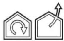
The hood is designed to be used either for exhausting or filter version.

Extraction version
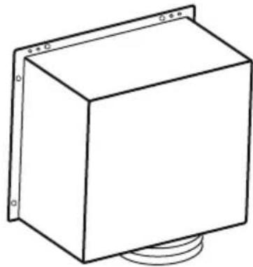
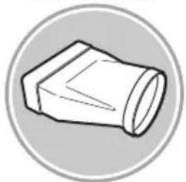
In this case the fumes are conveyed outside of the building by means of a special pipe connected with the connection ring located on top of the hood.

CAUTION!
The exhausting pipe is not supplied and must be purchased apart. Diameter of the exhausting pipe must be equal to that of the connection ring.

CAUTION!
If the hood is supplied with active charcoal filter, then it must be removed.

Filtration version
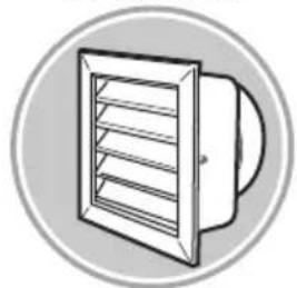
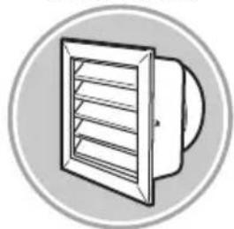
The aspirated air will be degreased and deodorised before being fed back into the room.
In order to use the hood in this version, you have to install a system of additional filtering based on activated charcoal.
Note: The recycled air in the charcoal filter is sent back to the kitchen through a duct which conveys air on a side of the cabinet.
The models with no suction motor only operate in ducting mode, and must be connected to an external suction device (not supplied).
The connecting instructions are supplied with the peripheral suction unit.
Mounting
Before starting to mount the appliance, make sure that no component is damaged, otherwise contact the dealer and stop mounting. In addition, read all the instructions below carefully.
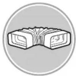
- Use an air outlet pipe no longer than 5 metres.
- Limit the number of curves in the duct since each curve reduces the suction effectiveness equivalent to 1 linear metre. (E.g.: if two 90^ curves are used, the duct should be no longer than 3 metres).
- Avoid drastic changes of direction.
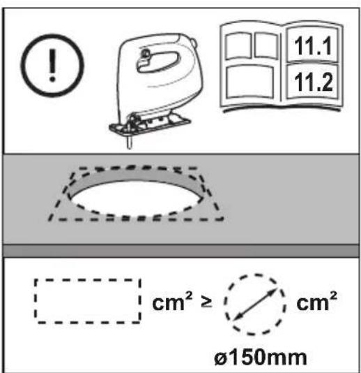
- Use a duct with 150mm diameter constant for the whole length.
- Use a duct made of standard complying material.
- In case of failure to observe the instructions above, the supplier can not be held responsible for capacity or noise problems and no warranty will be granted.
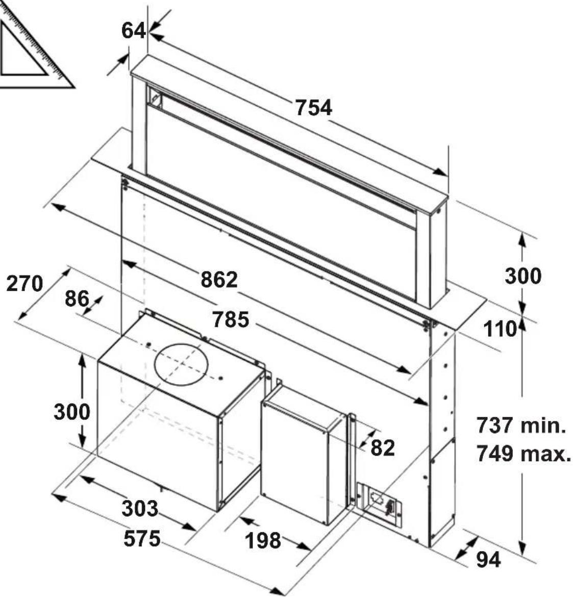
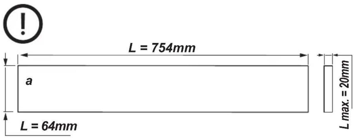
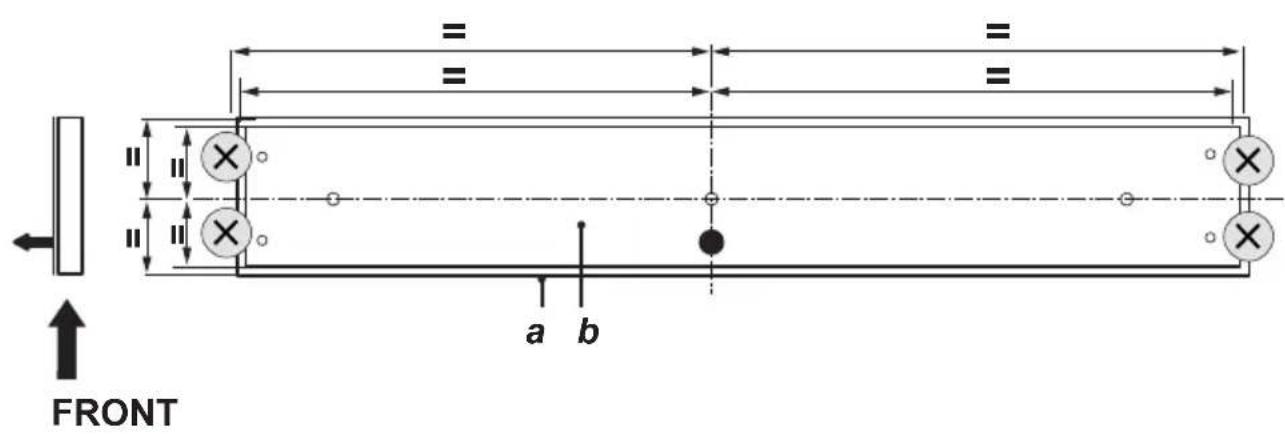
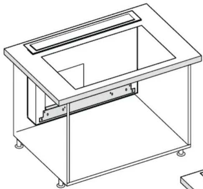
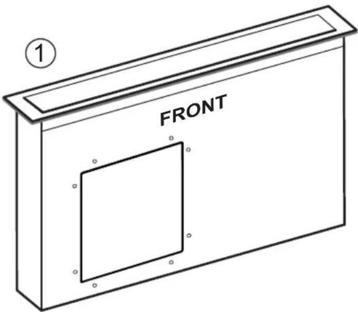
- Before making the hole, make sure that the inside of the cabinet, near the hood housing area, does not have the structure of the cabinet or other particulars which may cause problems for the proper installation. Make sure that the overall dimensions of the hood and the hob ae compatible with the cabinet and therefore the installation is feasible.
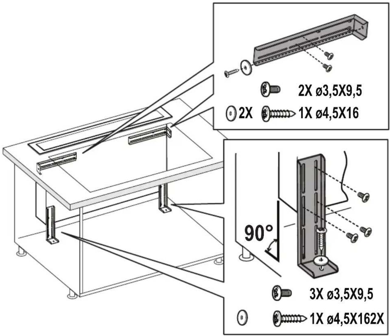
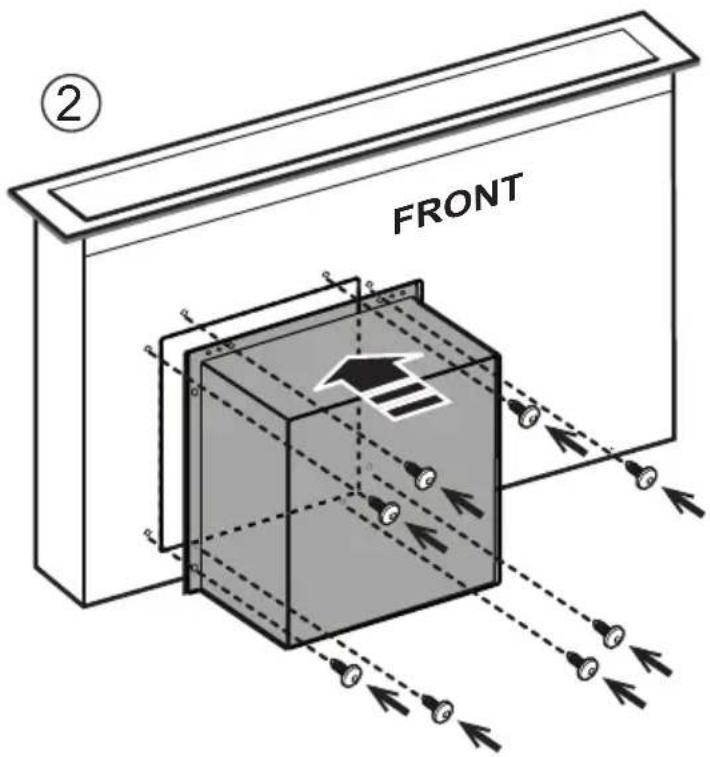
- Before inserting the screws into the cabinet, make sure that the product is perfectly perpendicular to the worktop.
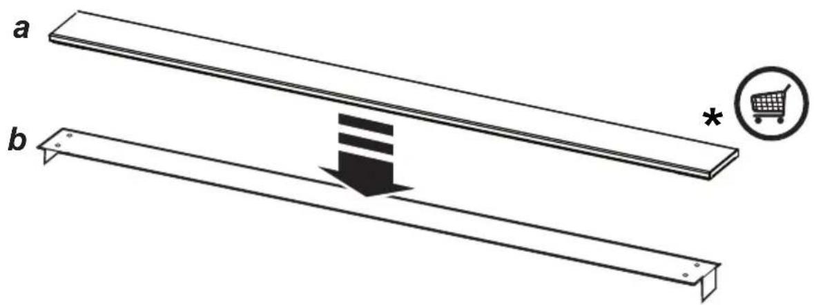
Panel Assembly
(only for models where the panel is not supplied with the hood)
CAUTION!
Installation must be carried out only by qualified installers. FOR THE INSTALLER: Responsibility for installation of the hood, including verification of the conformity of any fixing kit supplied with the product, is the sole responsibility of the installer. Following is a non-exhaustive list of helpful instructions for the installer:
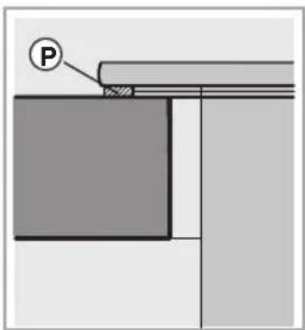
- use a fireproof PANEL (compliant with art. 30 of IEC/EN 60335-2-31), suitable for the operating temperature (at least 80^ ) and humidity (at least 93% ) reached during use;
- total weight of PANEL used should not exceed 1,5 kg;
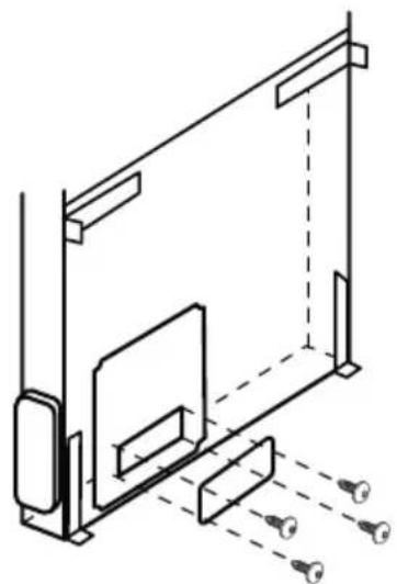
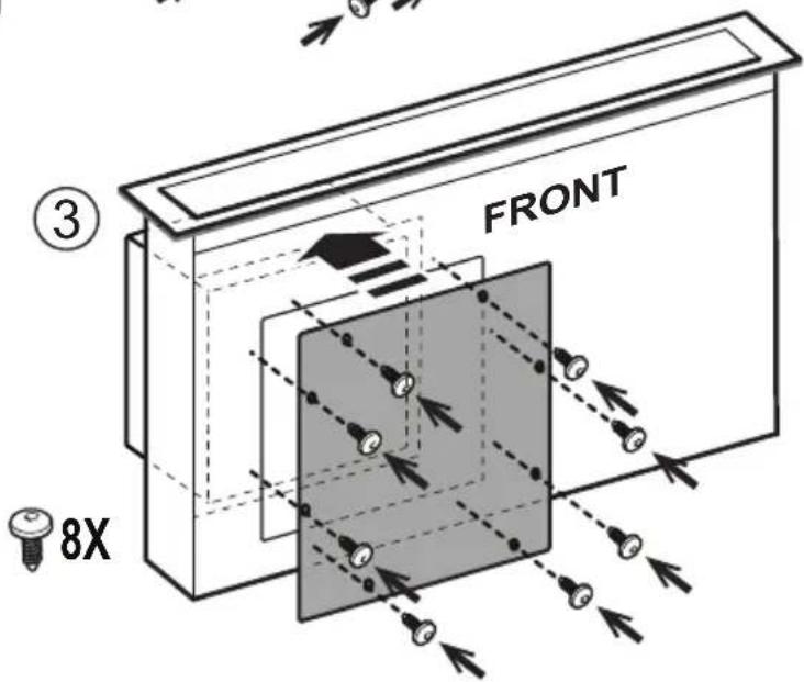
- secure the PANEL to the hood using the fixing points. See the illustrations dedicated to assembly of the panel not supplied with the hood.
- use suitable mechanical parts to fix the PANEL (not included in the assembly kit). Airforce denies all liability for damage to persons or property resulting from incorrect installation of the gypsum panels and/or product.
Operation
Control Display A
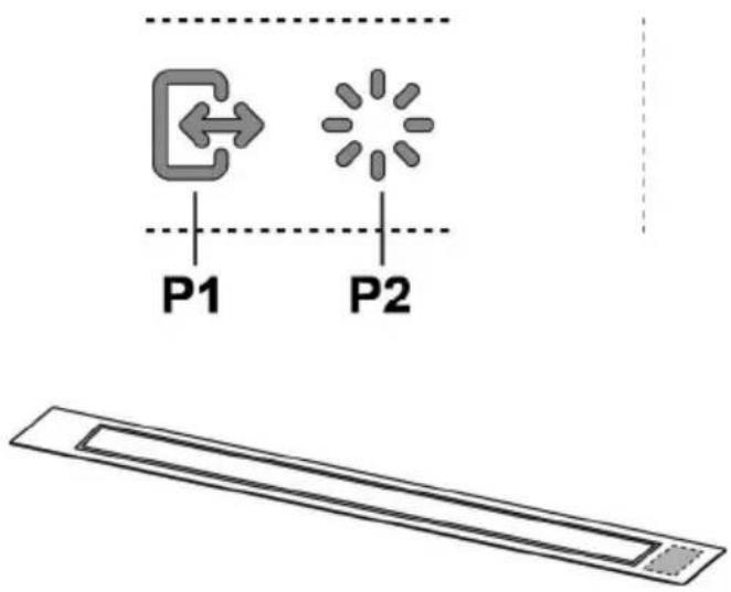
P1. Intake panel opening/closing button P2. Light ON/OFF button
P1. Intake panel opening/closing button
If the panel is CLOSED, by pressing button P1, the hood will turn on and the intake panel will be raised.
This operation will also give access to control display B, which manages motor and lighting.
If the panel is OPEN, by pressing button P1, the hood will turn off and the intake panel will be closed. This operation stops all active motor and lighting functions immediately.
Note: With the panel closed or while it is moving, control display B will remain deactivated. When the panel is completely open, it will be possible to use display B.
P2. Light ON/OFF button
If the panel is CLOSED, by pressing button P2, the hood will turn on, the intake panel will be raised and the lights will turn on only when the pull-out hood is completely open.
If the panel is OPEN, it will only be possible to turn the hood lights on and off.
Note: Light button P2 does not manage Light Dimming and does not turn the hood off.
Control Display B
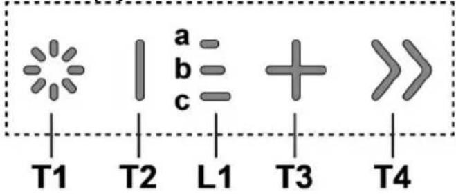
natural_image
Line drawing of a rectangular enclosure or enclosure with internal ventilation grilles (no text or symbols)T1. Light ON/OFF button
T2. Decrease intake speed / motor off button
L1. Speed indicator LED on
T3. Motor on / increase intake speed button
T4. "BOOST" - intensive speed - function button
T1: Light ON/OFF button
to turn the light on and off.
Press and hold button T1 to increase / decrease the intensity of the light.
T2: Decrease speed / motor off button
press the decrease the intake power, until the extractor hood is turned off.
press and hold to turn the hood off directly.
L1: Speed indicator LED on
the central LEDs light up according to the intake speed active/used:
1st speed, LED a will light up
2nd speed, LEDs a+b will light up
3rd speed, LEDs a+b+c will light up
T3: Increase speed button
press to turn the hood on
press to increase the intake power.
T4: "BOOST" – intensive speed - function button
press T4 to activate the intensive intake speed "BOOST 1", timed for 30 minutes
this prolonged timing has been designed to guarantee a suitable cooking time for preparations that release high amounts of smoke during cooking
Note: after the 30 minutes, the hood will go back to the previously set intake speed ***
with the motor on "BOOST 1", press T4 again to activate the intensive intake speed "BOOST 2", timed for 7 minutes
Note: after the 7 minutes, the hood will go back to the previously set intake speed ***
Note: press T4 again, during the 7 minutes, to go back to the previously set intake speed ***
with the "BOOST1" and "BOOST2" functions active, press:
T2 to go back to the previously set intake speed ***
T3 to go back to the 3rd intake speed
*** the previous intake speed remains visible via the indicator LEDs L1
if you have set the intensive speed directly with the hood off, the motor will be turned off after the set time.
While using the "BOOST" functions, the T4 symbol flashes ("BOOST 1": white light - "BOOST 2": blue light)
Filter Saturation indicator lights
At regular intervals, the hood signals the need to perform maintenance on the filters.
LED L1 (a-b-c) on and flashing light (all indicator lights flashing together): perform maintenance on the grease filter.
LED L1 (a-b-c) on and alternating light (the indicator lights turn on in sequence): perform maintenance on the active carbon filter
Note: The filter saturation indicator is visible within the first 10 seconds on turning on the hood; the saturation indicators must be reset within this time.
Reset filter saturation indicator:
Press and hold button T3
LED L1 (a-b-c) turns on and off (depending on the type of filter being reset, the indicator lights flash together or turn on in sequence); an acoustic signal will confirm the reset operation.
Activation of filter saturation indicator
Note: this operation must be performed with the hood off.
- Grease filter
This indicator is normally activated 1st prolonged press of buttons T3 and T2
if the indicator is active, button T3 turns on press button T2, to deactivate it if the indicator is not active, button T2 turns on press button T3, to activate it
- Active carbon filter
This indicator is normally deactivated 2nd prolonged press of buttons T3 and T2
if the indicator is active, button T3 turns on press button T2, to deactivate it if the indicator is not active, button T2 turns on press button T3, to activate it
Note: 3rd prolonged press of buttons T3 and T2
Maintenance
Cleaning
Clean using ONLY a cloth dampened with neutral liquid detergent. DO NOT CLEAN WITH TOOLS OR
INSTRUMENTS. Do not use abrasive products. DO NOT USE ALCOHOL!
Grease filter
Traps cooking grease particles.
This must be cleaned once a month (or when the filter saturation indication system – if envisaged on the model in possession – indicates this necessity) using non aggressive detergents, either by hand or in the dishwasher, which must be set to a low temperature and a short cycle.
When washed in a dishwasher, the grease filter may discolor slightly, but this does not affect its filtering capacity.
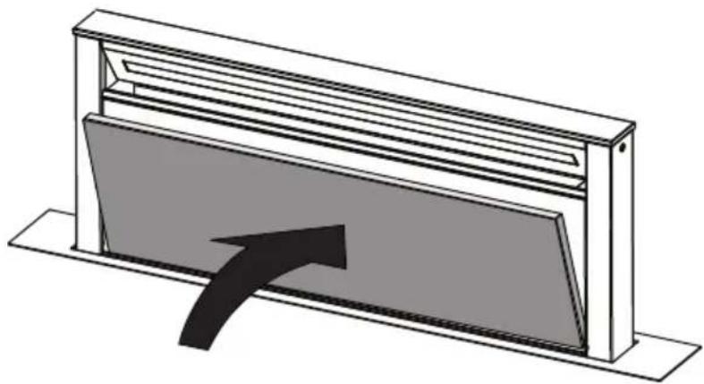
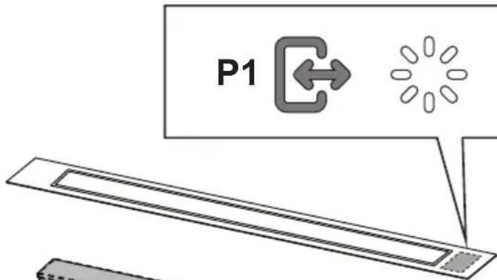
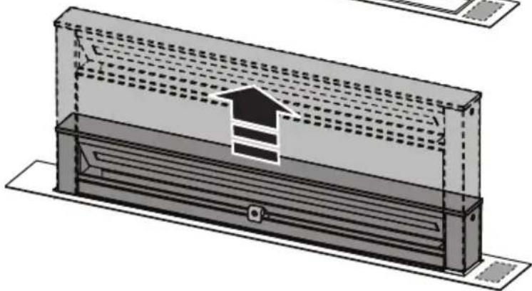
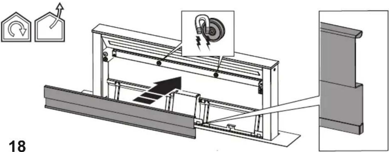
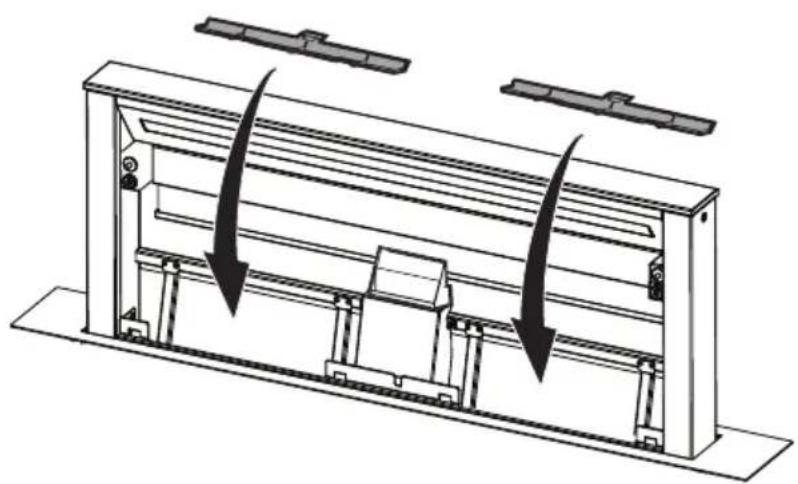
When inserting and removing grease filters and charcoal filters, please make sure that the extractable unit of the hood is in open position.
Then remove the front panel, by pulling on the upper part of each side at the same time.
The panel turns forward, so that grease filters can be inserted.
Fig. 18-21
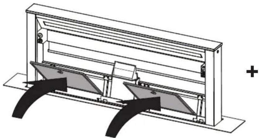
Charcoal filter (filter version only)
It absorbs unpleasant odors caused by cooking.
Washable activated charcoal filter
The charcoal filter can be washed once every two months (or when the filter saturation indication system – if envisaged on the model in possession – indicates this necessity) using hot water and a suitable detergent, or in a dishwasher at 65^ C (if the dishwasher is used, select the full cycle function and leave dishes out).
Eliminate excess water without damaging the filter, then put it in the oven for 10 minutes at 100^ C to dry completely. Replace the mattress every 3 years and when the cloth is damaged.
After removing the grease filter, it is possible to insert the charcoal filters (not supplied).
Replacing lamps
The hood is equipped with a lighting system based on LED technology.
The LEDs guarantee an optimum lighting, a duration up to 10 times longer than the traditional lamps and allow to save 90% electrical energy.
To replace lights, contact authorised spare part center.
flowchart
graph TD
    A["P1"] --> B["Arrow to left"]
    C["P2"] --> D["Star-like node"]
natural_image
Simple line drawing of a rectangular object with a central slot and a small square end (no text or symbols)natural_image
Technical line drawing of a rectangular enclosure or enclosure with internal ventilation grilles (no text or symbols)flowchart
graph TD
    A["P1"] --> B["Arrow to left"]
    C["P2"] --> D["Arrow to right"]
    style A fill:#f9f,stroke:#333
    style C fill:#f9f,stroke:#333

natural_image
Simple line drawing of a rectangular object with a recessed top and a small square on the side (no text or symbols)natural_image
Line drawing of a rectangular metal enclosure or enclosure with slatted top and base (no text or symbols)natural_image
Simple line drawing of a rectangular object with a recessed top and a small square indentation at the bottom (no text or symbols)
natural_image
Line drawing of a rectangular metal enclosure with ventilation grilles (no text or symbols)Activering indicator verzadiging filters
natural_image
Technical line drawing of a rectangular enclosure or enclosure with internal ventilation grilles (no text or symbols)natural_image
Technical line drawing of a rectangular enclosure or enclosure with internal ventilation grilles (no text or symbols)natural_image
Simple line drawing of a rectangular object with a recessed inner rectangle and a small square at the top (no text or symbols)natural_image
Technical line drawing of a rectangular enclosure or enclosure with horizontal slats and a flat base (no text or symbols)natural_image
Technical line drawing of a rectangular enclosure or enclosure with vertical slats and a flat base (no text or symbols)natural_image
Simple line drawing of a rectangular object with a central slot and a small square end (no text or symbols)natural_image
Technical line drawing of a rectangular enclosure or enclosure with vertical slats and a flat base (no text or symbols)natural_image
Technical line drawing of a rectangular enclosure or enclosure with internal ventilation grilles (no text or symbols)natural_image
Simple line drawing of a rectangular object with a recessed slot and a small square end (no text or symbols)natural_image
Technical line drawing of a rectangular enclosure or enclosure with internal ventilation grilles (no text or symbols)natural_image
Simple line drawing of a rectangular object with a recessed top and a small protrusion at the bottom (no text or symbols)natural_image
Line drawing of a rectangular metal enclosure or enclosure with a recessed top panel (no text or symbols)natural_image
Simple line drawing of a rectangular object with a recessed inner ring and a small square cutout on the right side (no text or symbols)natural_image
Technical line drawing of a rectangular enclosure or enclosure with internal ventilation grilles (no text or symbols)natural_image
Pure geometric diagram of a rectangular object with a central slot and a small square at the bottom (no text or symbols)P1. Tlačidlo otvorenia / zatvorenia odsávacieho panelu.
natural_image
Technical line drawing of a rectangular enclosure or enclosure with vertical slats and a base (no text or symbols)flowchart
graph TD
    A["P1"] --> B["←"]
    B --> C["P2"]

natural_image
Simple line drawing of a rectangular object with a recessed top and a small square at the bottom (no text or symbols)natural_image
Technical line drawing of a rectangular enclosure or enclosure with internal ventilation grilles (no text or symbols)- Waste Electrical and Electronic Equipment (WEEE).
natural_image
Simple line drawing of a rectangular object with a small square cutout on the top right corner (no text or symbols)natural_image
Technical line drawing of a rectangular enclosure or enclosure with internal ventilation grilles (no text or symbols)natural_image
Technical line drawing of a rectangular enclosure or enclosure with internal ventilation grilles (no text or symbols)natural_image
Simple line drawing of a rectangular object with a recessed top and a small square indentation at the bottom (no text or symbols)natural_image
Technical line drawing of a rectangular enclosure or enclosure with internal ventilation grilles (no text or symbols)flowchart
graph TD
    A["P1"] --> B["Arrow to left"]
    C["P2"] --> D["Circle with radiating dots"]

natural_image
Simple line drawing of a rectangular object with a recessed slot and a small square cutout on the side (no text or symbols)natural_image
Technical line drawing of a rectangular enclosure or enclosure with internal ventilation ducts (no text or symbols)natural_image
Simple line drawing of a rectangular object with a recessed inner rectangle and a small square cutout on the right side (no text or symbols)natural_image
Technical line drawing of a rectangular enclosure or enclosure with internal ventilation grilles (no text or symbols)natural_image
Simple line drawing of a rectangular object with a recessed top and a small square on the side (no text or symbols)P1. Tömbepaneeli avamine/sulgemine
P2. Valgustuse ON/OFF-nupp
P1. Tõmbepaneeli avamine/sulgemine
natural_image
Technical line drawing of a rectangular enclosure or enclosure with internal partition (no text or symbols)natural_image
Simple line drawing of a rectangular object with a recessed slot and a small square cutout at the bottom (no text or symbols)natural_image
Technical line drawing of a rectangular enclosure or enclosure with internal ventilation grilles (no text or symbols)natural_image
Simple line drawing of a rectangular object with a recessed inner rectangle and a small square cutout on the right side (no text or symbols)natural_image
Technical line drawing of a rectangular enclosure or enclosure with internal ventilation grilles (no text or symbols)T1. gaismas ON/OFF (iesl./izsl.) poga,
natural_image
Simple line drawing of a rectangular object with a recessed top and a small square cutout on the side (no text or symbols)P1. Taster za otvaranje/ zatvaranje ploče za usisavanje.
P2. Dugme za svetlo ON/OFF
P1. Taster za otvaranje/ zatvaranje ploče za usisavanje
Ako je ploča ZATVORENA s pritiskom na taster P1, napa se pali ploča za usisavanje se podiže.
Ovom radnjom omogućićete pristup i prikazu komandi B, koji upravlja motorom i osvetljenjem.
Ako je ploča OTVORENA, pritiskom na taster P1 napa se gasi, te se ovim zatvara i ploča za usisavanje. Ova radnja trenutno zaustavlja sve aktivne funkcije motora i osvetljenja.
natural_image
Technical line drawing of a rectangular enclosure or enclosure with internal ventilation grilles (no text or symbols)T1. Dugme za svetlo ON/OFF
T2. Dugme za Smanjivanje brzine usisavanja / Isključivanje motora
L1. Led svetla za signalizaciju aktivne brzine
T3. Dugme za Uključivanje motora / Povećavanje brzine usisavanja
T4. Dugme za funkciju "BOOST" - intenzivne brzine -
T1: Dugme za svetlo ON/OFF
natural_image
Simple line drawing of a rectangular object with a recessed cutout and a small square indentation (no text or symbols)natural_image
Technical line drawing of a rectangular enclosure or enclosure with vertical slats and a base (no text or symbols)T1. Tipka luči VKLOP/IZKLOP
natural_image
Technical line drawing of a rectangular enclosure or enclosure with internal ventilation grilles (no text or symbols)T1. Tipka za svjetlo ON/OFF
T2. Tipka za Smanjenje brzine usisavanja / Gašenje motora
L1. Led svjetla za signalizaciju aktivne brzine
T3. Tipka za Uključivanje motora / Povećanje brzine usisavanja
T4. Tipka funkcije "BOOST" - intenzivna brzina -
flowchart
graph TD
    A["P1"] --> B["Arrow to left"]
    C["P2"] --> D["Circle with dots"]
    style A fill:#f9f,stroke:#333
    style C fill:#f9f,stroke:#333
natural_image
Simple line drawing of a rectangular object with a central slot and a small square end (no text or symbols)natural_image
Technical line drawing of a rectangular enclosure or enclosure with internal ventilation grilles (no text or symbols)natural_image
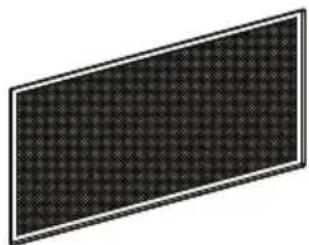
Simple line drawing of a three-layered rectangular frame (no text or symbols)1x
1x
1x
2x

4x
natural_image
Simple line drawing of a cable with a plug, labeled '1x' (no text or symbols on the diagram itself)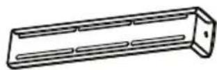
4x
8x
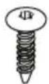
∅ 4,5 x 16 mm
natural_image
Rectangular panel with a grid pattern, no visible text or symbols2x

12x
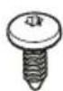
M4 x10 mm
10x
∅ 3,5 x 9,5 mm
natural_image
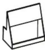
Simple line drawing of a rectangular box mounted on a vertical support with a base (no text or symbols)1x
natural_image
Line drawing of a rectangular electronic device with mounting holes and a central control panel (no text or symbols)1x
M2
1x
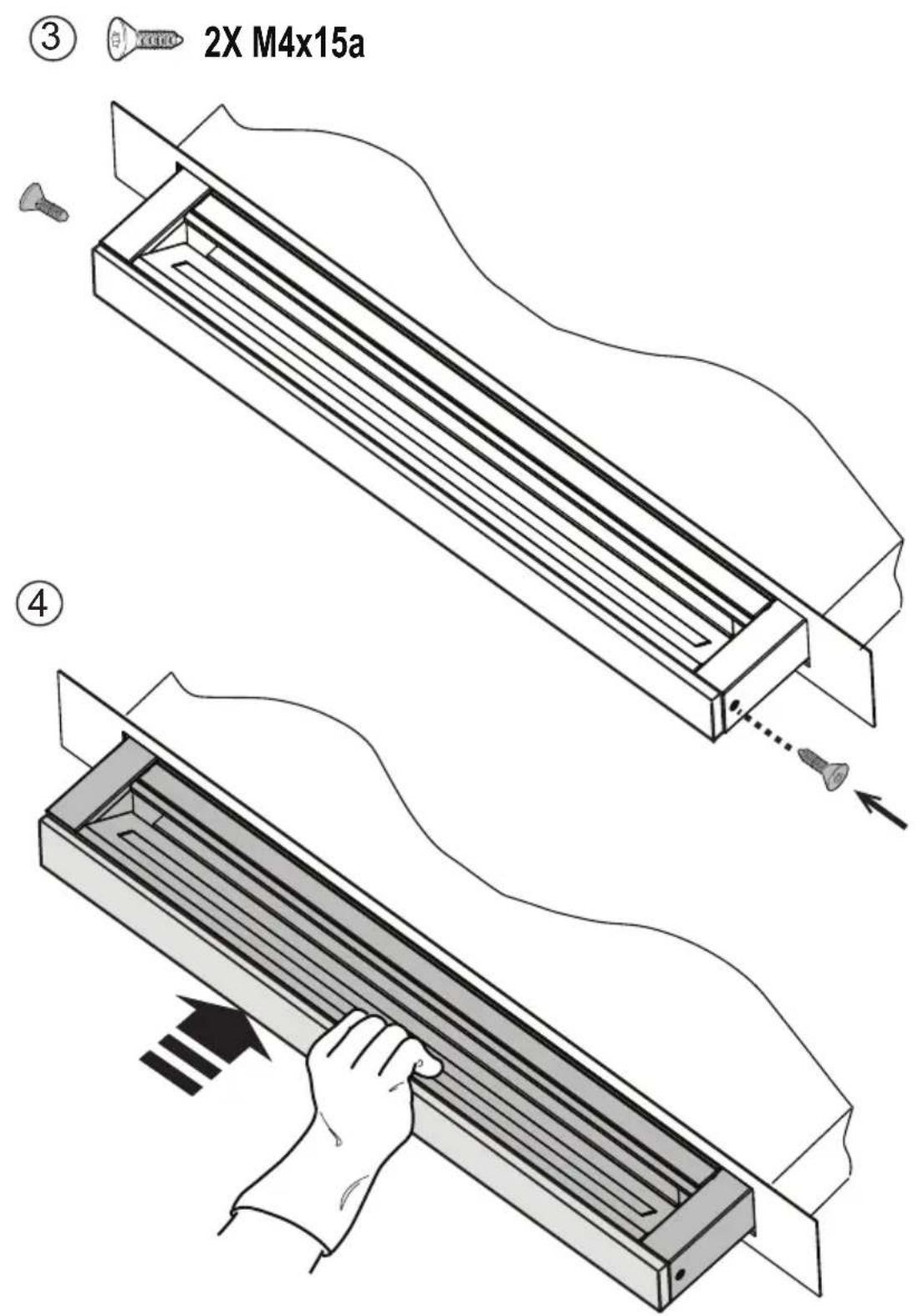
2x
M4x15 mm

natural_image
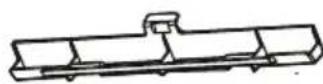
Simple line drawing of a rectangular beam with supports at both ends (no text or symbols)
natural_image
Simple line drawing of a solar panel with six panels and a star symbol on the top-left corner (no text or labels)2x
natural_image
3D-rendered gray rectangular block with a small asterisk symbol on the left (no text or symbols on the block itself)2x
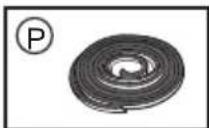
AFC4043002
natural_image
Simple line drawing of a bolt with threaded base and circular background (no text or symbols)AFC4043007
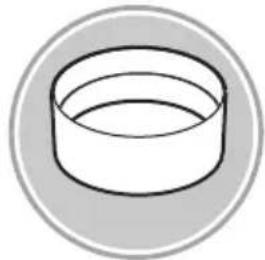
natural_image
Simple line drawing of a rectangular object with curved edges, enclosed in a circular border (no text or symbols)AFC4052102
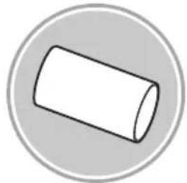
natural_image
Simple 3D illustration of a cylinder inside a gray circular border (no text or symbols)AFC4052017
natural_image
Simple line drawing of a cylindrical container inside a circular frame (no text or symbols)∅158x59mm
227x94 - ∅146mm ∅150x15000237x94mm
AFC4052015
natural_image
Simple line drawing of a cylindrical object with a flanged end, enclosed in a circular frame (no text or symbols)90°
AFC4043001
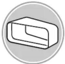
natural_image
Simple 3D illustration of a rectangular block inside a circular frame (no text or symbols)222x89x1000mm
AFC4043005
natural_image
Simple line drawing of a rectangular electronic component with a circular background (no text or symbols)227x94x80mm
AFC4043003
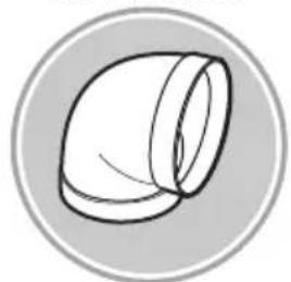
natural_image
Simple 3D geometric shape resembling a bent pipe or elbow, enclosed in a circular frame (no text or symbols)90° 227x288x94mm
AFC4043004
natural_image
Simple line drawing of a rectangular object inside a circular frame (no text or symbols)90° 227x94mm
AFC4043006
natural_image
Simple line drawing of a pipe fitting inside a circular frame (no text or symbols)227x94 - ∅153mm
AFGESTTR
natural_image
Simple line drawing of a ventilation duct with horizontal slats inside a circular frame (no text or symbols)190x190 - ∅147mm
AFGESTTQ
natural_image
Simple line drawing of a vent with airflow or ventilation duct (no text or symbols)INT 216X82mm EXT 290X160mm
AFTUBFGE
natural_image
Simple line drawing of two stacked rectangular blocks inside a circular frame (no text or symbols)227x94mm
V1
natural_image
Technical line drawing of a mechanical assembly with a central component and rectangular frame (no text or symbols)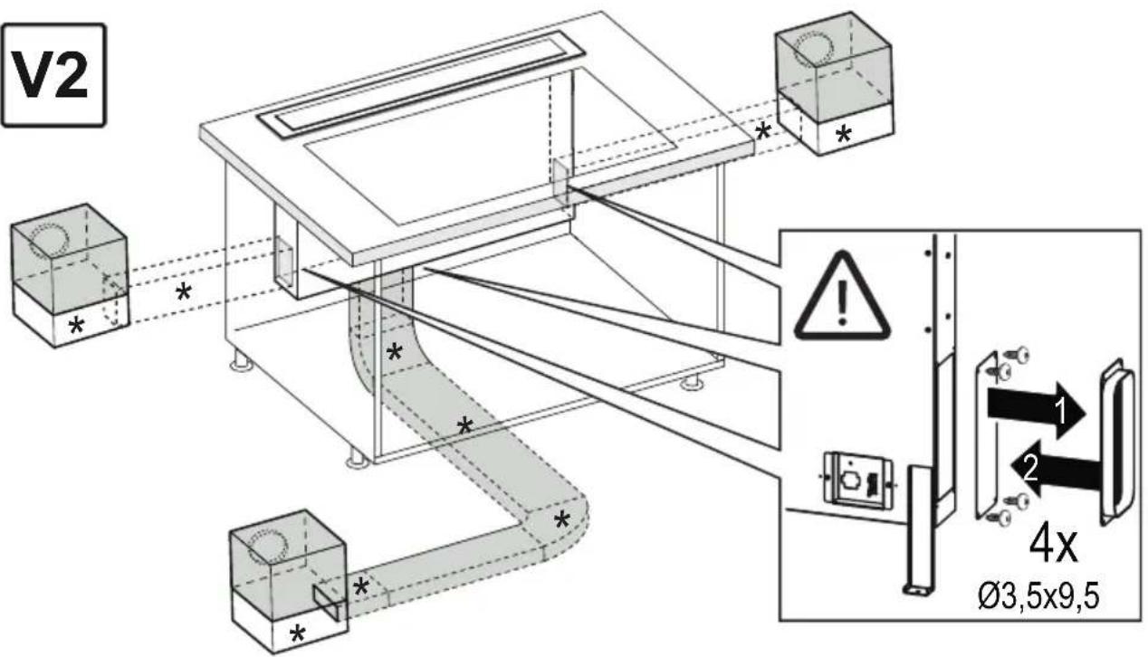
natural_image
Technical line drawing of a mechanical assembly with mounting brackets and a central panel (no text or symbols)4x ∅3,5x9,5 mm
natural_image
Technical line drawing of a rectangular metal enclosure or support structure (no text or symbols)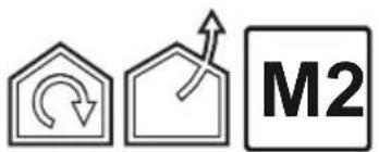
natural_image
Technical line drawing of a rectangular structural frame with mounting base (no text or symbols)
natural_image
Two identical black silhouette figures of men, no text or symbols present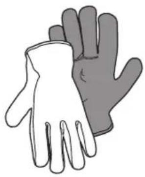
natural_image
Illustration of two hands in different colors (white and gray) with no text or symbols
1
3
3.1

natural_image
Line drawing of a simple rectangular box with a recessed top and side legs, no text or symbols present.4
natural_image
Simple diagram showing a downward arrow above a rectangular object and an exclamation mark inside a circle (no text or symbols)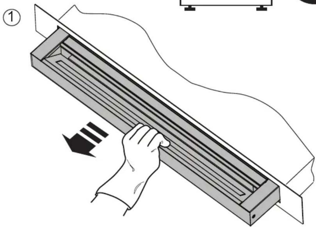
natural_image
Illustration of a hand using a tool to lift a rectangular object, with no visible text or symbols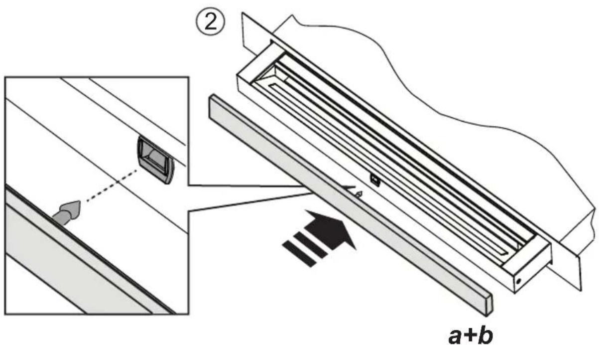
natural_image
Technical line drawing of a mechanical assembly with mounting feet and internal components (no text or symbols)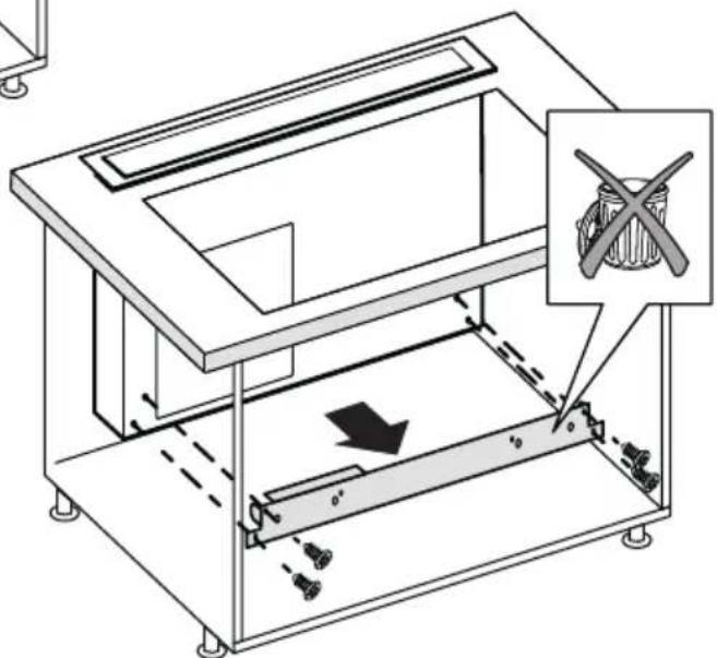
FRONT
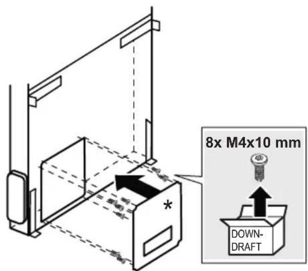
8X
[NO TEXT]
M4 × 10
BACK
8X
M4 × 10

14.1

14.2
natural_image
Isometric line drawing of a storage unit with a shopping cart icon and control panel (no text or symbols)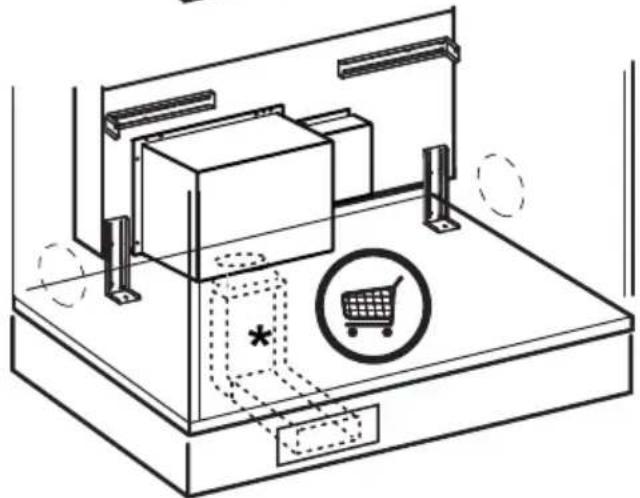
natural_image
Isometric line drawing of a printer setup with a box, printer stand, and shopping cart icon (no text or symbols)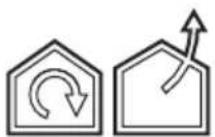
①
②
natural_image
Technical illustration of a mechanical ventilation system with a central duct and mounting base (no text or symbols)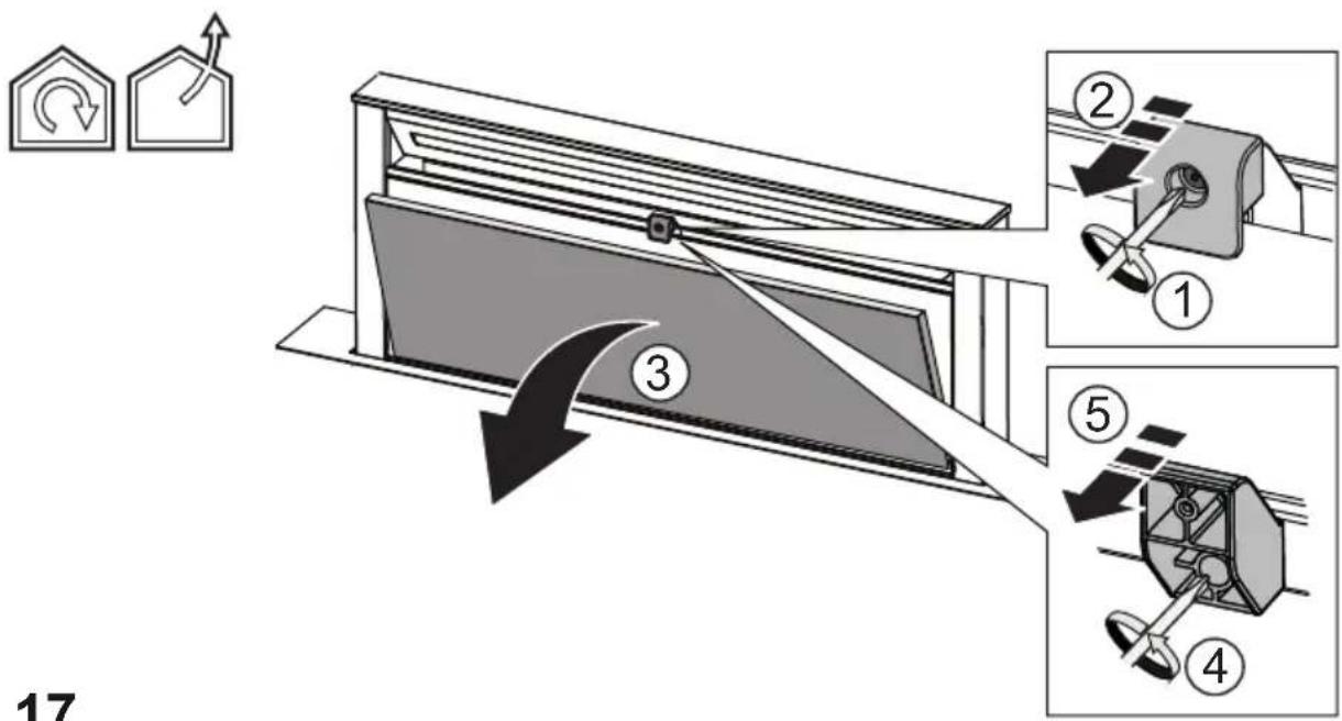
natural_image
Technical diagram of a mechanical device with directional arrows and component labels (no readable text or symbols)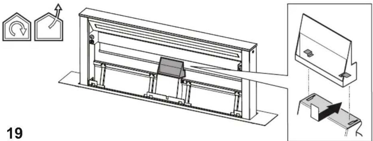
20
natural_image
Technical line drawing of a mechanical assembly with multiple components and directional arrows indicating motion (no text or symbols)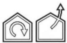
natural_image
Technical line drawing of a mechanical assembly with two supports and a central panel (no text or symbols)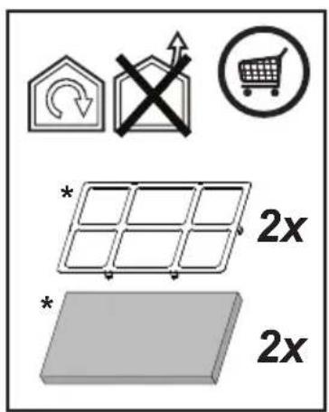
21
23