KAPEX KS 120 R - Saw FESTOOL - Free user manual and instructions
Find the device manual for free KAPEX KS 120 R FESTOOL in PDF.

User questions about KAPEX KS 120 R FESTOOL
0 question about this device. Answer the ones you know or ask your own.
Ask a new question about this device
Download the instructions for your Saw in PDF format for free! Find your manual KAPEX KS 120 R - FESTOOL and take your electronic device back in hand. On this page are published all the documents necessary for the use of your device. KAPEX KS 120 R by FESTOOL.
USER MANUAL KAPEX KS 120 R FESTOOL
natural_image
Mechanical cutting machine with green and black components, no visible text or symbols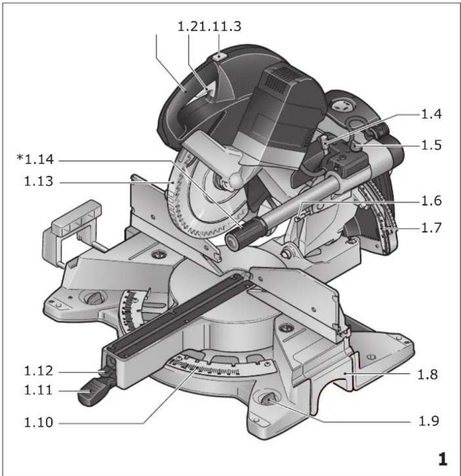
text_image
1.21.11.3 *1.14 1.13 1.4 1.5 1.6 1.7 1.12 1.11 1.8 1.9 1.10 1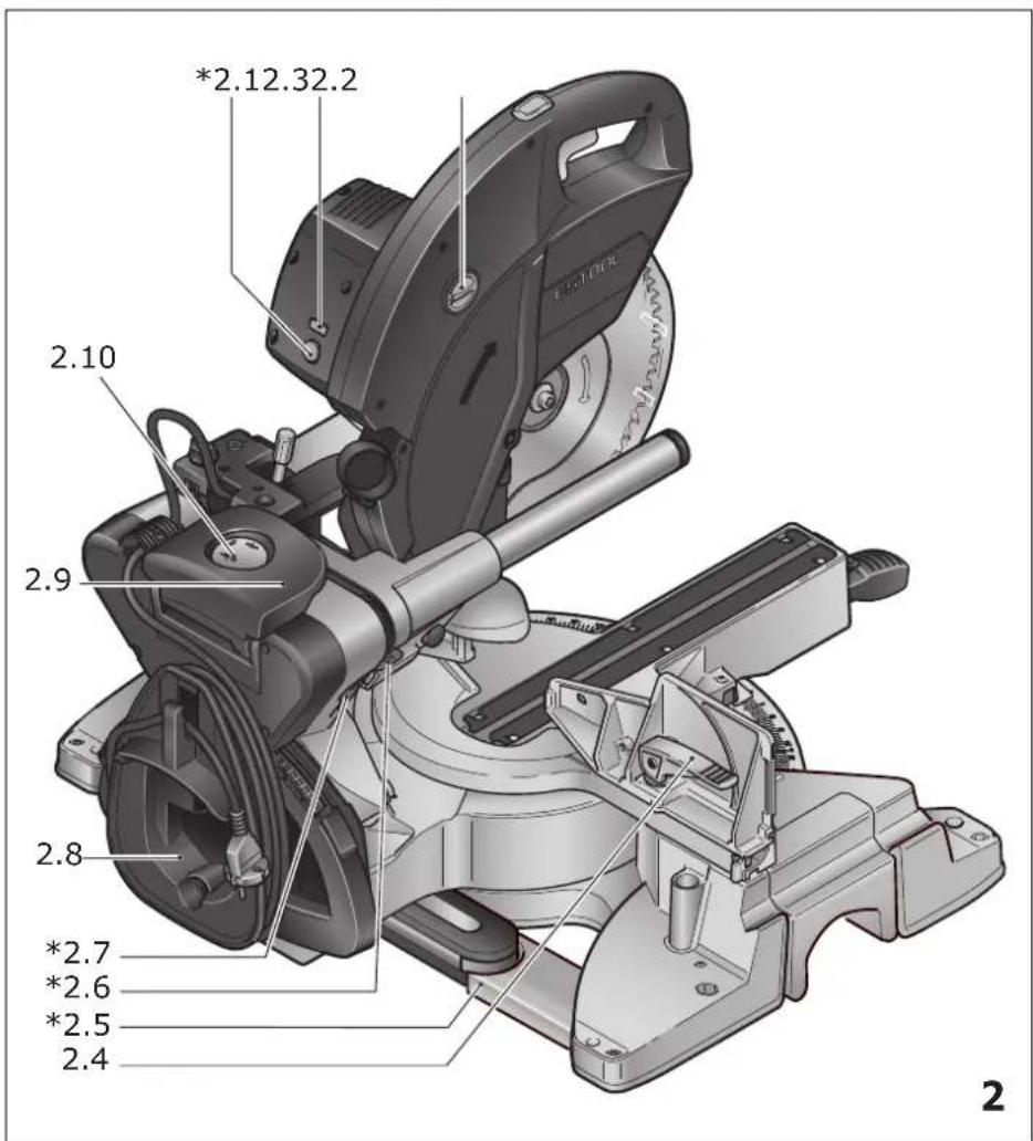
text_image
2.10 2.9 2.8 *2.7 *2.6 *2.5 2.4 *2.12.32.2 2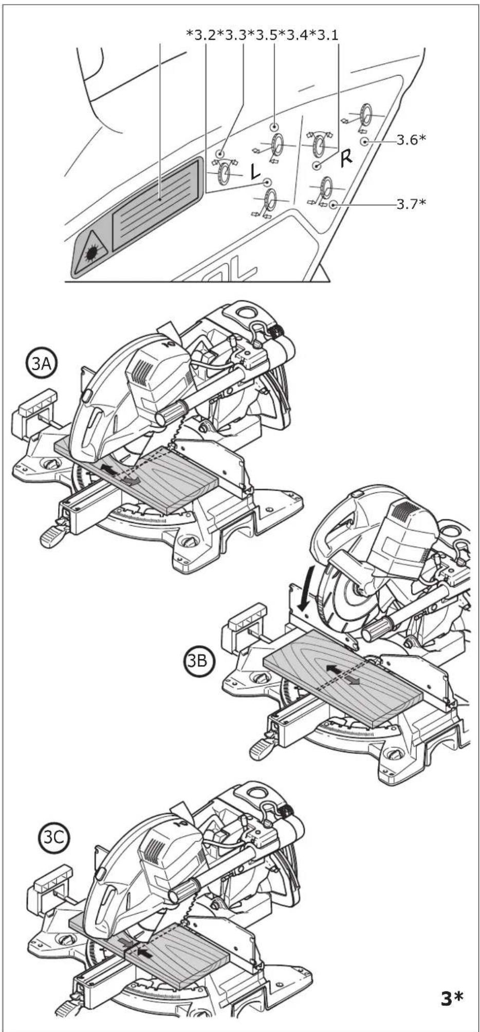
text_image
4.1 4.2 4.3 4.4 4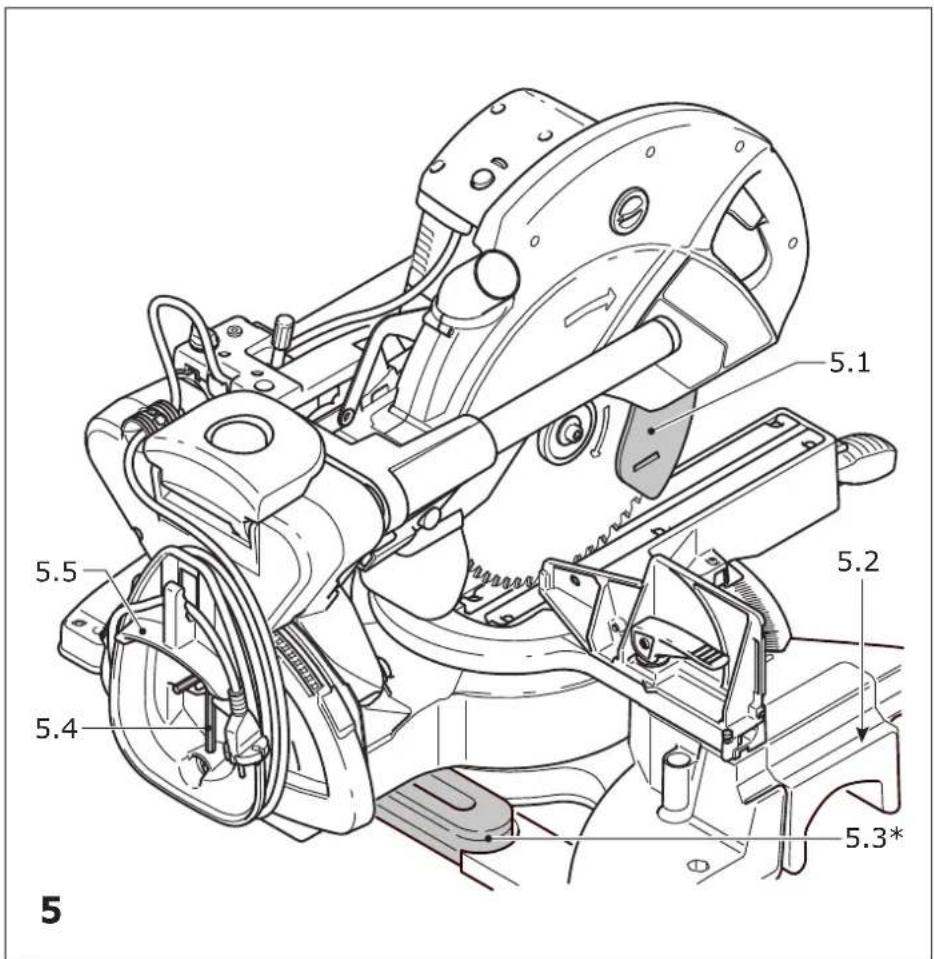
text_image
5.1 5.2 5.3* 5.4 5.5 5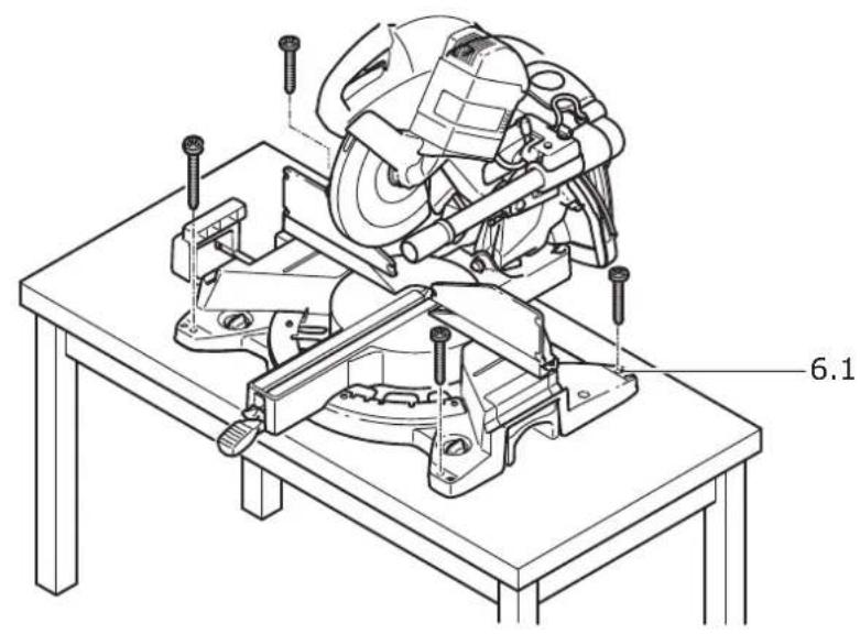
text_image
6.1
natural_image
Technical line drawing of a mechanical assembly with a cutaway view (no text or symbols)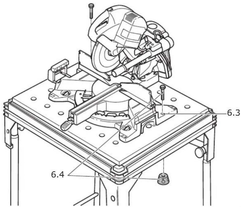
text_image
6.3 6.4| Zug- und KappsägeCircular cross-cut sawScie guidée | Seriennummer *Serial number *N° de série *(T-Nr.) |
| KS 120 REB | 10034767,10034768, 10028570 |
| KS 88 RE | 10034852,10034856, 10034855 |
EG-Konformitätserklärung. Wir erklären in alleiniger Verantwortung, dass dieses Produkt allen ein-schlägigen Bestimmungen der folgenden Richtlinien einschließlich ihrer Änderungen entspricht und mit den folgenden Normen übereinstimmt:
GB EC-Declaration of Conformity. We declare under our sole responsibility that this product is in conformity with all relevant provisions of the following directives including their amendments and complies with the following standards:
CE-Déclaration de conformité communautaire. Nous déclarons sous notre propre responsabilité que ce produit est conforme aux normes ou documents de normalisation suivants:
E CE-Declaración de conformidad. Declaramos bajo nuestra exclusiva responsabilidad que este producto corresponde a las siguientes normas o documentos normalizados:
CE-Dichiarazione di conformità. Dichiariamo sotto la nostra esclusiva responsabilità che il presente prodotto e conforme alle norme e ai documenti normativi seguenti:
NL EG-conformiteitsverklaring. Wij verklaren op eigen verantwoordelijkheid dat dit produkt voldoet aan de volgende normen of normatieve documenten:
⑤ EG-konformitetsförklaring. Vi förklarar i eget ansvar, att denna produkt stämmer överens med följande normer och normativa dokument:
FIN EY-standardinmukaisuusvakuutus. Va-kuutamme yksinvastuullisina, etta tuote on seu-raavien standardien ja normatiivisten ohjeiden mukainen:
DK EF-konformitetserklæring Vi erklærer at have alene ansvaret for, at dette produkt er i overensstemmelse med de følgende normer eller normative dokumenter:
N CE-Konformitetserklæring Vi erklærer på eget ansvar at dette produktet er i overensstemmelse med følgende normer eller normative dokumenter:
Head of Standardization & Approbation
links: 0^ , 15^ , 22,5^ , 30^ , 45^
rechts: 0°, 15°, 22,5°, 30°, 45°, 60°
1 Symbols....20
2 Safety warnings....20
3 Intended use....23
4 Specifications.... 23
5 Parts of the machine....23
6 Operation....24
7 Settings....25
8 Working with the power tool....27
9 Service and maintenance....29
10 Accessories.... 31
11 Environment....31
12 General information....31
1 Symbols

Warning of general danger

Warning of electric shock

Read the operating instructions and safety instructions.

Danger area! Keep hands away!

Wear protective goggles.

Wear a dust mask.

Wear ear protection.

Caution! Laser beams!

Wear protective gloves.

Do not dispose of it with domestic waste.

Safety class II

Tip or advice

Handling instruction

Electronics with adjustable, constant speed and temperature monitoring

FastFix tool replacement

Quick-acting brake for safe work

Wood

Laminated wooden panels

Eternit fibre cement panel

Aluminium

CE marking: Confirms the conformity of the power tool with the European Community directives.

UKCA marking: The United Kingdom Conformity Assessed symbol is a marking for products being placed on the market in the United Kingdom. It is a manufacturers indication that the product is in conformance with the relevant regulations in the UK.
2 Safety warnings
2.1 General power tool safety warnings

WARNING! Read all safety warnings, instructions, illustrations and specifications provided with this power tool. Failure to follow all instructions listed below may result in electric shock, fire and/or serious injury.
Save all warnings and instructions for future reference.
The term "power tool" in the warnings refers to your mains-operated (corded) power tool or battery-operated (cordless) power tool.
2.2 Safety instructions for mitre saws
- Mitre saws are intended to cut wood or wood-like products, they cannot be used with abrasive cut-off wheels for cutting ferrous material such as bars, rods, studs, etc. Abrasive dust causes moving parts such as the lower guard to jam. Sparks from abrasive cutting will burn the lower guard, the kerf insert and other plastic parts.
- Use clamps to support the workpiece whenever possible. If supporting the workpiece by hand, you must always keep your hand at least 100 mm from either side of the saw blade. Do not use this saw to cut pieces that are too small to be securely clamped or held by hand. If your hand is placed too close to the saw blade,
there is an increased risk of injury from blade contact.
- The workpiece must be stationary and clamped or held against both the fence and the table. Do not feed the workpiece into the blade or cut "freehand" in any way. Unrestrained or moving workpieces could be thrown at high speeds, causing injury.
- Push the saw through the workpiece. Do not pull the saw through the workpiece. To make a cut, raise the saw head and pull it out over the workpiece without cutting start the motor, press the saw head down and push the saw through the workpiece. Cutting on the pull stroke is likely to cause the saw blade to climb on top of the workpiece and violently throw the blade assembly towards the operator.
- Never cross your hand over the intended line of cutting either in front or behind the saw blade. Supporting the workpiece "cross handed" i.e. holding the workpiece to the right of the saw blade with your left hand or vice versa is very dangerous.
- Do not reach behind the fence with either hand closer than 100 mm from either side of the saw blade, to remove wood scraps, or for any other reason while the blade is spinning. The proximity of the spinning saw blade to your hand may not be obvious and you may be seriously injured.
- Inspect your workpiece before cutting. If the workpiece is bowed or warped, clamp it with the outside bowed face toward the fence. Always make certain that there is no gap between the workpiece, fence and table along the line of the cut. Bent or warped workpieces can twist or shift and may cause binding on the spinning saw blade while cutting. There should be no nails or foreign objects in the workpiece.
- Do not use the saw until the table is clear of all tools, wood scraps, etc., except for the workpiece. Small debris or loose pieces of wood or other objects that contact the revolving blade can be thrown with high speed.
- Cut only one workpiece at a time. Stacked multiple workpieces cannot be adequately clamped or braced and may bind on the blade or shift during cutting.
- Ensure the mitre saw is mounted or placed on a level, firm work surface be-
fore use. A level and firm work surface reduces the risk of the mitre saw becoming unstable.
- Plan your work. Every time you change the bevel or mitre angle setting, make sure the adjustable fence is set correctly to support the workpiece and will not interfere with the blade or the guarding system. Without turning the tool "ON" and with no workpiece on the table, move the saw blade through a complete simulated cut to assure there will be no interference or danger of cutting the fence.
- Provide adequate support such as table extensions, saw horses, etc. for a workpiece that is wider or longer than the table top. Workpieces longer or wider than the mitre saw table can tip if not securely supported. If the cut-off piece or workpiece tips, it can lift the lower guard or be thrown by the spinning blade.
- Do not use another person as a substitute for a table extension or as additional support. Unstable support for the workpiece can cause the blade to bind or the workpiece to shift during the cutting operation pulling you and the helper into the spinning blade.
- The cut-off piece must not be jammed or pressed by any means against the spinning saw blade. If confined, i.e. using length stops, the cut-off piece could get wedged against the blade and thrown violently.
- Always use a clamp or a fixture designed to properly support round material such as rods or tubing. Rods have a tendency to roll while being cut, causing the blade to "bite" and pull the work with your hand into the blade.
- Let the blade reach full speed before contacting the workpiece. This will reduce the risk of the workpiece being thrown.
- If the workpiece or blade becomes jammed, turn the mitre saw off. Wait for all moving parts to stop and disconnect the plug from the power source and/or remove the battery pack. Then work to free the jammed material. Continued sawing with a jammed workpiece could cause loss of control or damage to the mitre saw.
- After finishing the cut, release the switch, hold the saw head down and wait for the blade to stop before removing the cut-off
English
piece. Reaching with your hand near the coasting blade is dangerous.
- Hold the handle firmly when making an incomplete cut or when releasing the switch before the saw head is completely in the down position. The braking action of the saw may cause the saw head to be suddenly pulled downward, causing a risk of injury.
2.3 Tools and tool parts
- Always use the correct size of saw blade with a compatible location hole (e.g. star-shaped or circular). Saw blades that do not fit correctly with the assembly parts will run unevenly and may cause fragments to break off from the material and be ejected. These fragments may hit the eyes of the user or any persons standing in the vicinity.
- Deformed or cracked saw blades and saw blades with blunt or broken cutting edges must not be used.
- Only use saw blades that are designed for at least the maximum speed of the saw.
- Only transport the saw blade in suitable packaging. We recommend you use the original packaging.
- Use only saw blades recommended by the tool manufacturer, and suitable for sawing the materials to be cut. This prevents overheating of the saw teeth during sawing.
2.4 Further safety instructions
- Only use saw blades that correspond to the specifications for intended use. Saw blades that do not fit correctly with the assembly parts will run unevenly and may cause fragments to break off from the material and be ejected. These fragments may hit the eyes of the user or any persons standing in the vicinity.
- Only use saw blades with a chip angle ≤slant 0^ . A chip angle >0^ will pull the saw into the workpiece. There is a risk of injury caused by saw kickback and the rotating workpiece.
- Before each use, check that the pendulum guard is working correctly. Only use this power tool when it is in perfect working order.
- Never reach into the chip ejector with your hands. Rotating parts may injure your hands.
- Dust that is harmful to your health may be produced as you work (e.g. paint products
containing lead and some types of wood). Contact with or inhalation of this dust may pose a risk for the operating personnel or persons in the vicinity. Observe the safety regulations that apply in your country.
- We are a P2 respiratory mask to protect your health. In enclosed spaces, ensure that there is sufficient ventilation and connect a mobile dust extractor.
- Replace any sawn-off or damaged limit stops. Damaged limit stops may be ejected when you work with the saw. Any persons standing in the vicinity of the saw may be injured.
- Only use original Festool accessories and consumables. Only accessories tested and approved by Festool are safe and perfectly adapted to the machine and application.
- The power tool should only be used indoors and in a dry environment.
- Only for AS/NZS: The tool shall always be supplied via residual current device with a rated residual current of 30 mA or less.

2.5 Aluminium processing
When sawing aluminium, the following measures must be taken for safety reasons:
- Install an upstream residual-current circuit breaker (RCD, PRCD).
- Connect the power tool to a suitable dust extractor.
- Regularly clean dust deposits from the motor housing on the power tool.
- Use an aluminium saw blade.

Wear protective goggles.
2.6 Laser-specific safety information
- Never direct the laser beam at people. It may cause accidents as a result of the glare.
- Never look directly into the laser beam or its reflection. However, if you make direct contact with the laser beam, close your eyes immediately and move your head from the beam. Direct eye contact with the laser beam can cause damage to the eye.
- Do not make any modifications to the laser. A modified laser can generate additional risks.
2.7 Other risks
In spite of compliance with all relevant design regulations, dangers may still present themselves when the machine is operated, e.g.:
- Touching rotating parts from the side: Saw blade, clamping flange, flange screw,
- Touching live parts when the housing is open and the mains plug is still plugged in,
- Workpiece parts being thrown off,
- Parts of damaged tools being thrown off,
- Noise emissions,
- Dust emissions.
2.8 Emission levels
The levels determined in accordance with EN 62841 are typically:
Sound pressure level L
$$ _ {\mathrm{PA}} = 8 8 \mathrm{dB(A)} $$
Sound power level L
$$ _ {\mathrm{WA}} = 1 0 1 \mathrm{dB(A)} $$
Uncertainty K = 3 dB

CAUTION
Noise generated when working Risk of damage to hearing
▶ Use ear protection.
The specified noise emission values
- have been measured in accordance with a standardised test procedure, can be used to compare one power tool with another,
- and can also be used for a provisional assessment of the load.

CAUTION
Depending on how the power tool is used, particularly which type of workpiece is being machined, the noise emitted by the power tool during use may deviate from the specified values.
▶ To protect the operator, safety measures should be defined based on load estimates obtained under real conditions of use. (All parts of the operating cycle must be taken into account here, including, for example, times in which the power tool is switched off or when it is switched on but idling.)
3 Intended use
The power tool is a stationary unit designed for sawing blocks of wood, plastic, aluminium profiles and similar materials. Do not use it to process other materials, in particular steel, concrete and mineral materials.
Only use Festool saw blades that are designed for use in this power tool.
The saw blades must comply with the following data:
- Saw blade diameter 260 mm
- Cutting width 2.5 mm (corresponds to the tooth width)
- Locating bore 30 mm
- Standard blade thickness1.8 mm
- Saw blade in accordance with EN 847-1
- Saw blade with chip angle ≤slant 0^
Festool saw blades for woodworking comply with EN 847-1.
Only saw materials for which the saw blade in question has been designed.
This power tool may only be used by experts or instructed persons.

The user is liable for damage and accidents caused by improper and non-intense.
4 Specifications
| Mitre saw KS 120 REB, | KS 88 RE |
Performance
| 220-240 V | 1600 W |
| 110 V | 1400 W |
| Speed (idle) | 1400-3600 rpm |
Tool spindle dia. 30 mm
Weight according to EPTA-Procedure 01:2014
| KS 120 REB | 24 kg |
| KS 88 RE | 23 kg |
For maximum workpiece dimensions see the section
5 Parts of the machine
[1.1] Handle
[1.2] On/off switch
[1.3] Safety lock
[1.4] Cutting depth limiter lever
[1.5] Rotary knob for clamping the pulling unit
[1.6] Transport lock
[1.7] Scale for mitre angle (vertical)
[1.8] Extension table
English
[1.9] Rotary knob for extension table
[1.10] Scale for mitre angle (horizontal)
[1.11] Clamping lever for mitre angle (horizontal)
[1.12] Notch lever for preset mitre angle (horizontal)
[1.13] Pendulum guard
[1.14] Rotary handle for precision adjustment of mitre angle (vertical)*
[2.1] On/off switch for laser*
[2.2] Speed adjusting wheel
[2.3] FastFix spindle stop
[2.4] Clamping lever for stop ruler
[2.5] Bevel holder
[2.6] Release lever for special cutting position*
[2.7] Lever for special cutting position*
[2.8] Cable winder with integral carry handle
[2.9] Clamping lever for mitre angle (vertical)
[2.10] Selector switch for mitre angle range (vertical)
The components marked with an * on the figures are only included in the scope of delivery of the KS 120 REB.
The illustrations specified are located at the beginning and end of the operating instructions.
6 Operation

WARNING
Unauthorised voltage or frequency.
Risk of accidents
- The mains voltage and the frequency of the power source must correspond to the specifications on the name plate.
▶ In North America, only Festool machines with the voltage specifications 120 V/60 Hz may be used.
Before initial operation
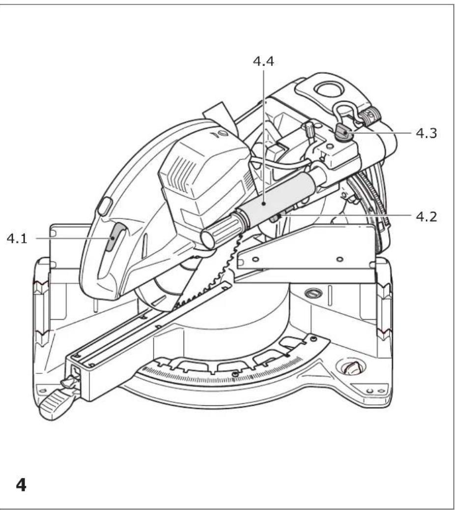
- Remove the transport safety device [4.4] on the guide rod.
Switching on/off
- Press the on/off switch until you feel resistance in order to unlock the saw unit and the pendulum guard.
- Press the safety lock [1.3].
- Press the on/off switch [1.2] all the way in to switch on the machine.
- Release the on/off switch again to switch off the machine.
6.1 Setting up the machine

WARNING
Risk of injury, electric shock
▶ Always disconnect the mains plug from the socket before performing any work on the machine.
Install the machine on a level and stable work surface before using it (e.g. the UG-KAPEX underframe, the MFT multifunction table or a workbench).
You have the following installation options
Screws: Use four screws to secure the machine to the work surface. Use the holes [6.1] at the four support points on the saw table to do this.
Fastening clamps: Use four fastening clamps to secure the machine to the work surface. The flat surfaces [6.2] at the four support points on the saw table can be used as clamping surfaces.
Clamping set (for MFT): Secure the machine onto the Festool MFT multifunction table using the clamping set [6.4, 494693] . Use the two screw holes [6.3] to do this.
UG-KAPEX underframe: attach the machine to the underframe as described in the assembly instructions which accompany the underframe.
6.2 Transportation
Securing the machine (transport position)
▶ Press the on/off switch [4.1].
▶ Swivel the saw unit down all the way to the stop.
▶ Press the lock [4.2]. The saw unit will now remain in the lower position.
▶ Tighten the rotary knob [4.3] to secure the saw unit in the rear position.
- Wrap the power cable onto the cable winder [5.5] for transport.
▶ Put the hex key [5.4] and the bevel [5.3] (KS 120 REB only) away in the holders intended for this purpose.

WARNING
Risk of injury
▶ Never lift or carry the machine by the movable pendulum guard [5.1].
▶ To carry the machine, hold it by the side of the saw table [5.2] and by the carry handle [5.5] in the cable winder.
Unlocking the machine (working position)
▶ Push the saw unit down slightly and pull the transport safety device [4.2].
▶ Swivel the saw unit upwards.
▶ Unscrew the rotary knob [4.3].
7 Settings

WARNING
Risk of injury, electric shock
▶ Always disconnect the mains plug from the socket before performing any work on the machine.
KS 120 REB only: Replace the adhesive warning label [3.1] for the laser with the label in your language that is enclosed with the tool.
7.1 Selecting the saw blade
Festool saw blades are identified by a coloured ring. The colour of the ring represents the material for which the saw blade is suited.
Colour Material Symbol
Yellow Wood

Green Eternit fibre cement panels

Blue Aluminium, plastic

7.2 Tool replacement

WARNING
Risk of injury
▶ Observe the following instructions:
- Disconnect the mains plug from the socket before changing tools.
- Only use the spindle stop [7.2] when the saw blade is at a standstill.
- The saw blade becomes very hot during operation; do not touch it before it has cooled down.
- Wear protective gloves due to the risk of injury from sharp blades while changing tools.
Removing the saw blade
▶ Move the machine into the working position.
▶ Press the spindle stop [7.2] and turn it clockwise by 90°.
▶ Fully loosen the screw [7.8] using the hex key [7.9] (left-hand thread).
▶ Press the on/off switch [7.3] and open the lock of the pendulum guard.
▶ Fully open the pendulum guard [7.4].
- Remove the clamping flange [7.7] and the saw blade.
Fitting the saw blade
▶ Clean all parts before installing them (saw blade, flange, screw).
▶ Place the saw blade on the tool spindle [7.5].

WARNING
Risk of injury
▶ Make sure that the rotational directions of the saw blade [7.6] and the machine [7.1] correspond to each other.
- Secure the saw blade with the flange [7.7] and the screw [7.8].
▶ Firmly tighten the screw [7.8] (left-hand thread).
▶ Press the spindle stop [7.2] and turn it anticlockwise by 90°.
7.3 Workpiece clamp
Fitting the workpiece clamp
▶ Fit the workpiece clamp [8.1] into one of the two holes [8.2]. The clamping unit must point towards the rear.
▶ Twist the workpiece clamp so that the clamping unit faces forward.
7.4 Dust extraction

WARNING
Health hazard posed by dust
▶ Always work with an extractor.
▶ Comply with national regulations.
▶ Wear a dust mask.
A Festool dust extractor with an extractor hose diameter of 36 mm or 27 mm (36 mm recommended due to the reduced risk of clogging) can be connected to the extractor connector [9.1].
English
The flexible chip deflector [9.2] improves the collection of dust and chips. Therefore, never work without a fitted chip deflector.
The chip deflector is clamped in position on the guard with the clamp [10.1] . For this, the hooks [10.2] of the clamp must lock into the recesses [10.3] of the guard.
7.5 Adjusting the table extension
▶ Open the rotary knob [1.9].
▶ Pull out the table extension [1.8] far enough that the workpiece is laid out fully.
▶ Close the rotary knob.
If, despite the table extension being extended as far as possible, the workpiece protrudes over the table, the workpiece must be supported by other means.
7.6 Workpiece stop
Adjusting the stop ruler
For mitre cuts, you must adjust the stop rulers [11.1] so that they do not impede the functionality of the pendulum guard or come into contact with the saw blade.
▶ Open the clamping lever [11.2].
▶ Move the stop ruler until the shortest distance to the saw blade when working is a maximum of 4.5 mm.
▶ Close the clamping lever again.
Removing the stop ruler
A stop ruler may need to be removed for some mitre cuts, since it may otherwise collide with the saw unit.
▶ Insert the screw [11.3] into the threaded hole and tighten it as far as possible (downwards).
▶ You will then be able to pull out the stop ruler sideways.
▶ Loosen the screw again by three rotations once you have reinserted the stop ruler.
Auxiliary stop
To increase the stop area, you can install an auxiliary stop made of wood [12.2] in the holes [12.1] in each of the two stop rulers. This allows you to set up larger workpieces more securely.
In doing this, be aware of the following:
- The screws you use to secure the auxiliary stops must not protrude from the surface.
- The auxiliary stops must only be used for 0^ cuts.
- The auxiliary stops must not impede the functionality of the guards.
7.7 Horizontal mitre angle
The horizontal mitre angle can be continuously adjusted between 50^ (left side) and 60^ (right side). In addition, there are snap-in positions for common mitre angles.
The arrow of the indicator [13.2] points to the set horizontal mitre angle. The two markings on the right and left of the indicator arrow enable precise setting of half-degree angles. For this to work, both of these markings must line up with the degree dashes on the scale.
Standard horizontal mitre angles
The following mitre angles have snap-in positions:
Left: 0^ , 15^ , 22.5^ , 30^ , 45^
Right: 0^ , 15^ , 22.5^ , 30^ , 45, 60^
▶ Move the machine into the working position.
▶ Pull the clamping lever [13.5] upwards.
▶ Press the notch lever [13.4] downwards.
▶ Rotate the saw table until you get to the mi-tre angle you want.
▶ Release the notch lever. You must feel the notch lever engage.
▶ Press the clamping lever downwards.
Optional horizontal mitre angles
▶ Move the machine into the working position.
▶ Pull the clamping lever [13.5] upwards.
▶ Press the notch lever [13.4] downwards.
▶ Rotate the saw table until you get to the mi-tre angle you want.
▶ Press the clamping lever downwards.
▶ Release the notch lever.
▶ Move the machine into the working position.
▶ Open the clamping lever [14.1].
▶ Turn the selector switch [14.2] to the adjustment range you would like (0^-45^, +/-45^ or +/-47^) .
- Swivel the saw unit until the indicator [14.3] points to the mitre angle you would like. KS 120 REB only: you can fine-tune the setting of the vertical mitre angle using the rotary handle for precision adjustment [14.4].
▶ Close the clamping lever[14.1] again.
7.9 Special cutting position
Besides the usual position for cutting or trimming boards/panels, the machine has a special cutting position for trimming slats with heights of up to 120 mm.
▶ Pull the saw unit forwards.
▶ Swivel the lever [15.3] downwards.
▶ Push the saw unit back until the metal bracket [15.1] hooks into the rear opening of the saw unit.
In this position, you can now trim slats of up to 120 mm in height at the stop. The pull function and the vertical swivel function of the mitre saw are deactivated, however.
▶ To bring the machine back into its standard position, press the release lever [15.2] and pull the saw unit forwards. This will unhook the metal bracket [15.1] and the lever [15.3] will swivel back.
7.10 Cutting depth limiter
The continuously adjustable cutting depth limiter can be used to set the vertical swivelling range of the saw unit. Doing this enables workpieces to be grooved or faced.
① Be aware of the limited grooving range: Continuous adjustment is only possible within the range 0 to 45 mm. The possible length of the groove is also limited. E.g.: At a groove depth of 48 mm and a workpiece thickness of 88 mm, this range lies between 40 and 270 mm.
▶ Move the machine into the working position.
▶ Swivel the lever for the cutting depth limiter [16.1] downwards until it clicks into place. The saw unit can now be swivelled down only as far as the preset cutting depth.
▶ Set the cutting depth you would like by turning the cutting depth limiter lever.
▶ To deactivate the cutting depth limiter, swivel the cutting depth limiter lever back up again.
7.11 Fixed horizontal position
You can clamp the saw unit in place in any position you want along the guide rods [16.3] using the rotary knob [16.2] .
7.12 Switching on the laser (KS 120 REB only)
The machine has two lasers which mark the kerf to the left and right of the saw blade. You can use them to align the workpiece on both sides (left or right side of the saw blade/kerf).
▶ Press the button [2.1] to switch the laser on or off. If the machine is not in use for 30 minutes, the laser will automatically switch itself off and must be switched on again.
8 Working with the power tool

WARNING
Flying tool parts/workpiece parts Risk of injury
▶ Wear protective goggles.
▶ Ensure that no other persons are close to the machine while it is being used.
▶ Always clamp workpieces tightly.
▶ The clamps must be fully laid out.

WARNING
The pendulum guard does not close Risk of injury
▶ Stop the sawing process.
▶ Unplug the mains cable and remove waste. In the event of damage, remove the pendulum guard.

WARNING
Risk of injury
▶ Observe the following instructions:
- Correct working position:
- At the front on the side of the operator;
- Head-on to the saw;
-
Beside the line of cut.
-
During operation, always hold the power tool tightly by the handle [1.1] in your operating hand. Always keep your free hand outside of the hazardous area.
- Always use and fix extension table [1.8] during operation (see chapter 7.5).
- Only guide the power tool towards the workpiece when it is switched on.
- Adjust the feed speed in order to prevent the machine from overloading and to prevent the plastic from melting if you are cutting plastics.
- Do not work on the power tool if its electronics are defective as this may lead to excessive speeds. You can tell if the electronics are defective if there is no smooth start-up, if it is not possible to regulate the speed and in the event of generation of smoke or the smell of burning from the machine.
- Before beginning work, ensure that the saw blade cannot touch the stop rulers, work-piece clamp, fastening clamps or other machine parts.
Always disconnect the mains plug from the socket when the power tool is not in use. This optimises the service life of the electronics.
8.1 Workpiece dimensions
Maximum workpiece dimensions without extension using accessory parts
| Mitre angles according to scale, horizontal/ vertical | Height x width [mm] |
| 0°/0° 88 × 305 | |
| 45°/0° 88 × 215 | |
| 0°/45° right 35 × 305 | |
| 0°/45° left 55 × 305 | |
| 45°/45° right 35 × 215 | |
| 45°/45° left 55 × 215 |
Maximum workpiece dimensions when installing together with the KA-KS 120
The maximum height and width of the workpiece do not change if accessory parts are installed.
Accessory part used Length
KA-KS 120 (one side) Up to 2400 mm
KA-KS 120 (both sides) Up to 4800 mm
Long workpieces
Provide extra support for any workpieces that protrude over the sawing surface:
▶ Adjust the extension table (see section 7.5).
▶ If the workpiece still protrudes, retract the extension table and install the KA-KS 120 trimming attachment (see section 8.1).
▶ Use additional clamps to secure the workpiece.
Thin workpieces
During sawing, thin workpieces may wobble or break.
▶ During sawing, thin workpieces may wobble or break.
▶ Reinforce the workpiece: Clamp it together with wood offcuts.
Heavy workpieces
▶ To guarantee the stability of the machine, even when sawing heavy workpieces, adjust the support foot so that it is flush with the base.
8.2 Check that the pendulum guard can move
The pendulum guard must always be able to move freely and close independently.
▶ Pull out the mains plug.
▶ Take hold of the pendulum guard and, as a trial run, slide it into the saw unit.
The pendulum guard must be easy to move and must be almost fully lowered into the pendulum hood.
Cleaning the area of the saw blade
▶ Always keep the area around the pendulum guard clean.
▶ Clear dust and chippings by blowing out with compressed air or using a brush.
8.3 Clamping the workpiece

WARNING
Risk of injury
▶ Observe the following instructions:
- Secure fit – always clamp the workpiece in position with the workpiece clamp. This requires the hold-down clamp [17.2] to be resting securely on the workpiece. (Note: Aids may be required depending on the workpiece contours, e.g. round contours). Do not process any workpieces that have not been securely clamped.
- Size – do not process workpieces that are too small. In the interests of safety, the cut piece remaining should be at least 30 mm long. Small workpieces may be pulled backwards by the saw blade and into the gap between the saw blade and the stop ruler.
- Take particular care that workpieces are not pulled backwards by the saw blade and into the gap between the saw blade and the stop ruler. The risk of this happening is especially high with horizontal mitre cuts.
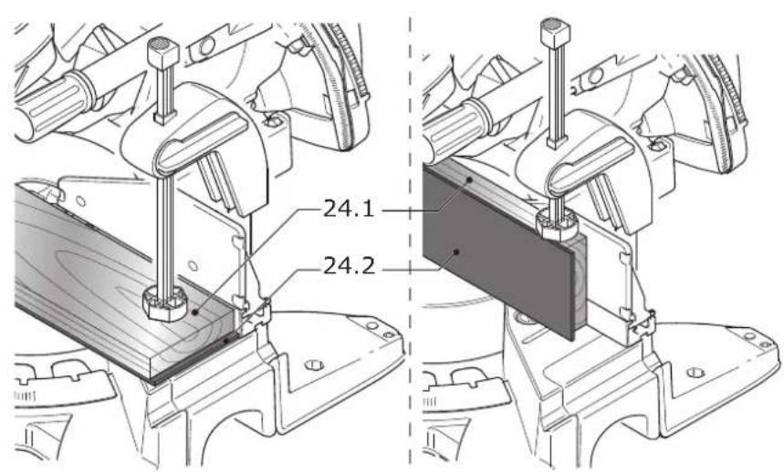
- Reinforce very thin workpieces [24.1] by sawing through them together with an additional wooden slat [24.2] to support them. During sawing, very thin workpieces may wobble or break.
Proceed as follows to clamp the workpiece
- Place the workpiece on the saw table and push it against the stop rulers.
▶ Open the clamping lever [17.1] of the workpiece clamp.
▶ Twist the work piece clamp until the hold-down clamp [17.2] is positioned over the workpiece.
▶ Lower the hold-down clamp onto the workpiece.
▶ Close the clamping lever [17.1].
8.4 Speed control
The speed can be continuously adjusted between 1400 and 3600 rpm using the adjusting wheel [2.2]. This enables you to optimise the cutting speed to suit each material.
Recommended position of the adjusting wheel
| Wood 3-6 |
| Plastic 3-5 |
| Fibre materials 1-3 |
| Aluminium and non-ferrous profiles 3-6 |
8.5 Cuts without pull movement
▶ Adjust the machine settings to the settings you would like.
▶ Clamp the workpiece in position.
▶ Push the saw unit towards the rear all the way to the stop (in the direction of the workpiece stop) and tighten the rotary knob [1.5] for clamping the pulling unit or secure the saw unit in the special cutting position (KS 120 REB only).
▶ Switch on the machine.
- Slowly guide the saw unit downward by the handle [1.1] and saw through the workpiece at an even feed rate.
- Switch the machine off and wait until the saw blade has come to a complete standstill.
▶ Swivel the saw unit back up.
8.6 Cuts with pull movement
▶ Adjust the machine settings to the settings you would like.
▶ Clamp the workpiece in position.
▶ Pull the saw unit forwards along the guide rods.
▶ Switch on the machine.
- Slowly guide the saw unit downwards by the handle [1.1].
▶ Push the saw unit towards the rear at an even feed rate and saw the workpiece.
▶ Switch off the machine.
▶ Wait until the saw blade has come to a complete standstill and only then swivel the saw unit upwards.
8.7 Bevel (KS 120 REB only)
The bevel can be used to gauge any angle (e.g. between two walls). The bevel therefore forms the angle bisection.
Gauging the interior angle
▶ Open the clamp [18.2].
▶ Place the bevel with the two routers [18.1] against the interior angle.
▶ Close the clamp [18.2].
Gauging the exterior angle
▶ Open the clamp [18.3].
▶ Push the aluminium profiles [18.4] of the two routers forwards.
▶ Place the bevel with the two routers [18.4] against the exterior angle.
▶ Close the clamp [18.3].
▶ Push the aluminium profiles of the two routers back again.
Transferring the angle
- Place the bevel with one router against the stop ruler of the mitre saw.
▶ To set the angle bisector (horizontal mitre angle), swivel the saw unit until the laser beam is congruent with the line [19.1] of the bevel.
To do so, the bevel must be positioned so that it is parallel to the stop of the compound mitre saw. At the same time, apply pressure to the stop ruler by pressing in the recessed grip with your thumb.
9 Service and maintenance

WARNING
Risk of injury, electric shock
▶ Always pull the mains plug from the socket before performing any servicing and maintenance work.
▶ All maintenance and repair work which requires the motor housing to be opened should always be carried out by an authorised service workshop.
▶ Damaged safety devices and components must be repaired or replaced in a recognised specialist workshop, unless otherwise indicated in the operating instructions.
▶ Regularly clean the table top insert [20.1] as well as the extraction channel of the chip deflector (see figure 10) by blowing out with compressed air or using a brush to remove wood chips, dust deposits and remains of workpieces.
English
▶ To ensure constant air circulation, always keep the cooling air openings in the housing clean and free of blockages.

Cleaning the machine regularly, especially the adjusting devices and guides, is important safety factor.
The tool is equipped with special self-disconnecting carbon brushes. If they wear out, the power supply is disconnected automatically and the tool stops.

Customer service and repairs must only be carried out by the manufacturer or service workshops. Find the nearest address at: www.festool.co.uk/service
Always use original Festool spare parts. Order no. at: www.festool.co.uk/service
9.1 Adjusting the laser (KS 120 REB only)

The laser beam has been set correctly during manufacture. Only turn the adjusting screws out of position in the cases that are specified.
If the laser beams do not align with the cutting edge, you can readjust the two lasers. Use a screwdriver (2.5 mm width) to do this.
▶ Pierce the adhesive labels at the marked locations ([3.2] to [3.7]) with the screwdriver to access the adjusting screws underneath.
▶ Insert a sample workpiece into the machine to check the laser.
▶ Saw a groove into the workpiece.
▶ Swivel the head of the saw upward and check the setting.
The laser beam is not visible
▶ Switch on the laser [1.2]
▶ Identify which of the lasers is not visible.
▷ Turn the adjusting screws [3.3] for the left and [3.5] for the right laser beam until the laser appears on your workpiece.
▷ As described, first set the (a) parallelism to the scribe mark, then (b) the inclination and finally, (c) the axial displacement of the laser beam.
a) The laser is not parallel to the scribe mark [figure 3A]
Adjust the parallelism.
Left laser beam Adjusting screw [3.4]
Right laser beam Adjusting screw [3.6]
b) During trimming, the laser beam migrates to the left or right [figure 3B]
Set the inclination until the laser beam no longer migrates during trimming.
Left laser beam Adjusting screw [3.3]
Right laser beam Adjusting screw [3.5]
c) The laser beam is not in the same place as the cut [figure 3C]
Adjust the axial displacement.
Left laser beam Adjusting screw [3.2]
Right laser beam Adjusting screw [3.7]
9.2 Correcting horizontal mitre angles
If the indicator [13.2] of the snap-in mitre angles no longer points to the set value, you can adjust the indicator after loosening the screw [13.1].
Should the actual (sawn) mitre angle deviate from the angle you set, this can be corrected:
▶ Lock the saw unit in the 0^ position.
▶ Loosen the three screws [13.3] which secure the scale onto the saw table.
- Move the scale with the saw unit until it matches the actual 0^ value. You can check this against an angle between the stop ruler and the saw blade.
▶ Retighten the three screws [13.3].
▶ Check the angle adjustment by making a sample cut.
9.3 Correcting vertical mitre angles
Should the actual value no longer correspond to the angle you set, this can be corrected:
▶ Lock the saw unit in the 0^ position.
▶ Loosen the two screws [23.1].
- Swivel the saw unit until it matches the actual 0° value. You can check this against an angle between the saw table and the saw blade.
▶ Retighten the two screws [23.1].
▶ Check the angle adjustment by making a sample cut.
Should the indicator [22.2] no longer point to the set value, you can adjust it after loosening the screw [22.1].
9.4 Replacing the table top insert
Do not work with a worn-out table top insert [20.1]; replace it with a new one instead.
▶ Unscrew the six screws [20.2] to replace the table top insert.
9.5 Cleaning/replacing the window for the laser (KS 120 REB only)
The window [21.2] which protects the laser can become dirty during operation. You can remove the window to clean or replace it.
▶ Loosen the screw [21.5] by approx. two rotations.
▶ At the same time, push the window in directions [21.3] and [21.4].
▶ Remove the window.
▶ Clean the window or replace it with a new one.
▶ Insert the cleaned/new window. The two pins [21.1] of the window must engage in the recesses of the upper guard as show in figure 21.
▶ Tighten the screw [21.5].
10 Accessories
Use only original Festool accessories.
Refer to the Festool catalogue for the order numbers of accessories and tools or find them online at www.festool.co.uk.
In addition to the accessories described, Festool also provides a comprehensive range of system accessories that allow you to use your saw more effectively and in diverse applications, e.g.:
- Saw blades for different materials.
• KA-KS 120 table extension
• UG-KAPEX KS 120 underframe
• AB KS 120 crown stop
11 Environment

Do not dispose of the device in the household waste! Recycle devices, accessories and packaging. Observe appli-national regulations.
EU only: In accordance with the European Directive on waste electrical and electronic equipment and implementation in national law, used power tools must be collected separately and handed in for environmentally friendly recycling.
Information on REACH: www.festool.com/reach
12 General information
Imported into the UK by
Festool UK Ltd
1 Anglo Saxon Way
Bury St Edmunds
IP30 9XH
Great Britain
Sommaire
links: 0^ , 15^ , 22,5^ , 30^ , 45^
rechts: 0°, 15°, 22,5°, 30°, 45°, 60°
2.5 Aluminiumbearbetning

Sikre maskinen (transportstilling)
Kolor Material Symbol
Declaration of Conformity
We as the manufacturer Festool GmbH, Wertstraße 20, 73240 Wendlingen, Germany declare under our sole responsibility that the product(s):
Designation:
Designation of Type(s):
Serial number(s) 11:
Mitre saw
KS 120 REB
10034767, 10034768
fulfills all the relevant provisions of the following UK Regulations:
S.I. 2008/1597
S.I. 2016/1091
S.I. 2012/3032
Supply of Machinery (Safety) Regulations 2008
Electromagnetic Compatibility Regulations 2016
Restriction of the Use of Certain Hazardous Substances in Electrical and Electronic Equipment Regulations 2012
and are manufactured in accordance with the following designated standards:
• BS EN 62841-1: 2015
• BS EN IEC 62841-3-9:2020+A11:2020
• BS EN 55014-1:2017
• BS EN 55014-2:2015
• BS EN IEC 61000-3-2:2019
• BS EN 61000-3-3:2013
• BS EN IEC 63000:2018
1) in the specified serial number range (S-Nr.) from 400000000 - 499999999

Place and date of declaration: Wendlingen, 15.04.2021
Signed on behalf of and in name of Festool GmbH
$$ p p a. 1 0 8 $$
Markus Stark
Head of Productdevelopment
i.v. Q. Brundt
Ralf Brandt
Head of Productconformity

text_image
7.17.37.2 7.4 7.5 7.6 7.7 7.8 7.9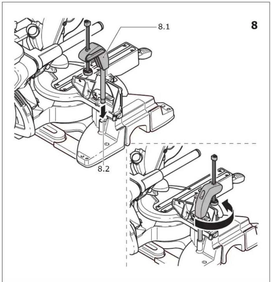
text_image
8.1 8 8.2 8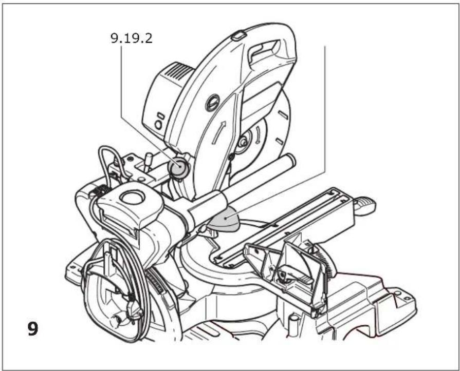
text_image
9.19.2 9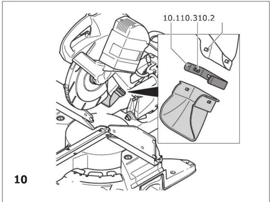
text_image
10.110.310.2 10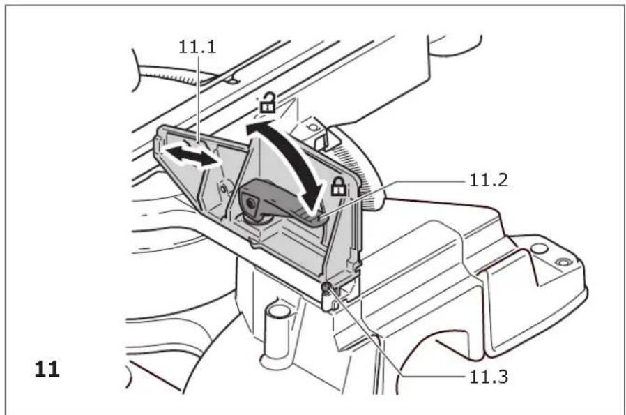
text_image
11.1 11.2 11 11.3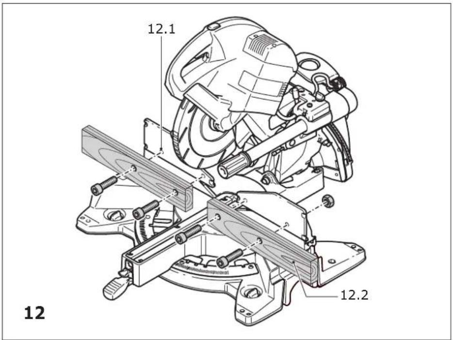
text_image
12.1 12.2 12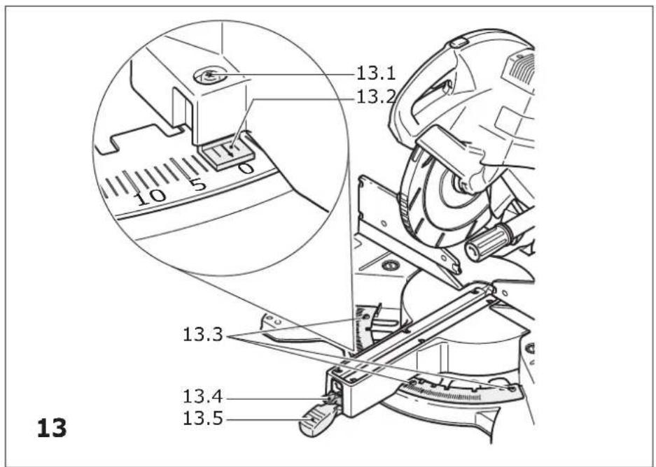
text_image
13.1 13.2 10 5 0 13.3 13.4 13.5 13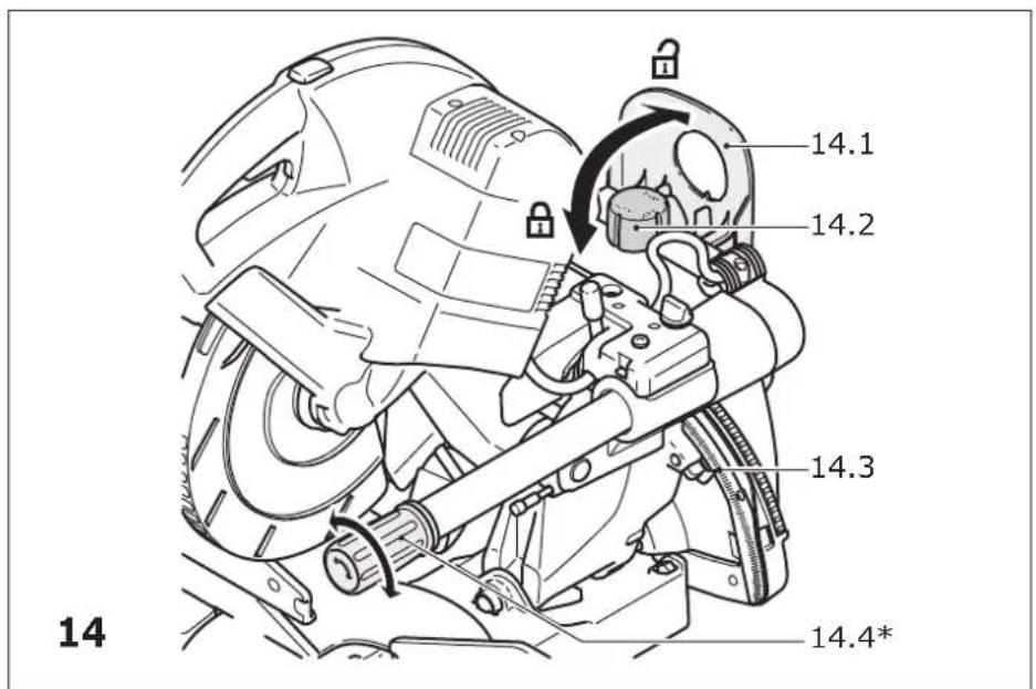
text_image
14.1 14.2 14.3 14.4*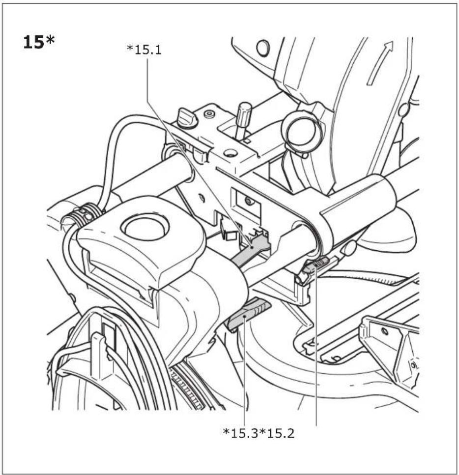
text_image
15* *15.1 *15.3*15.2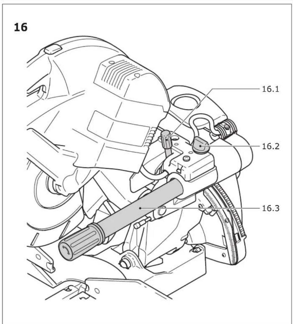
text_image
16 16.1 16.2 16.3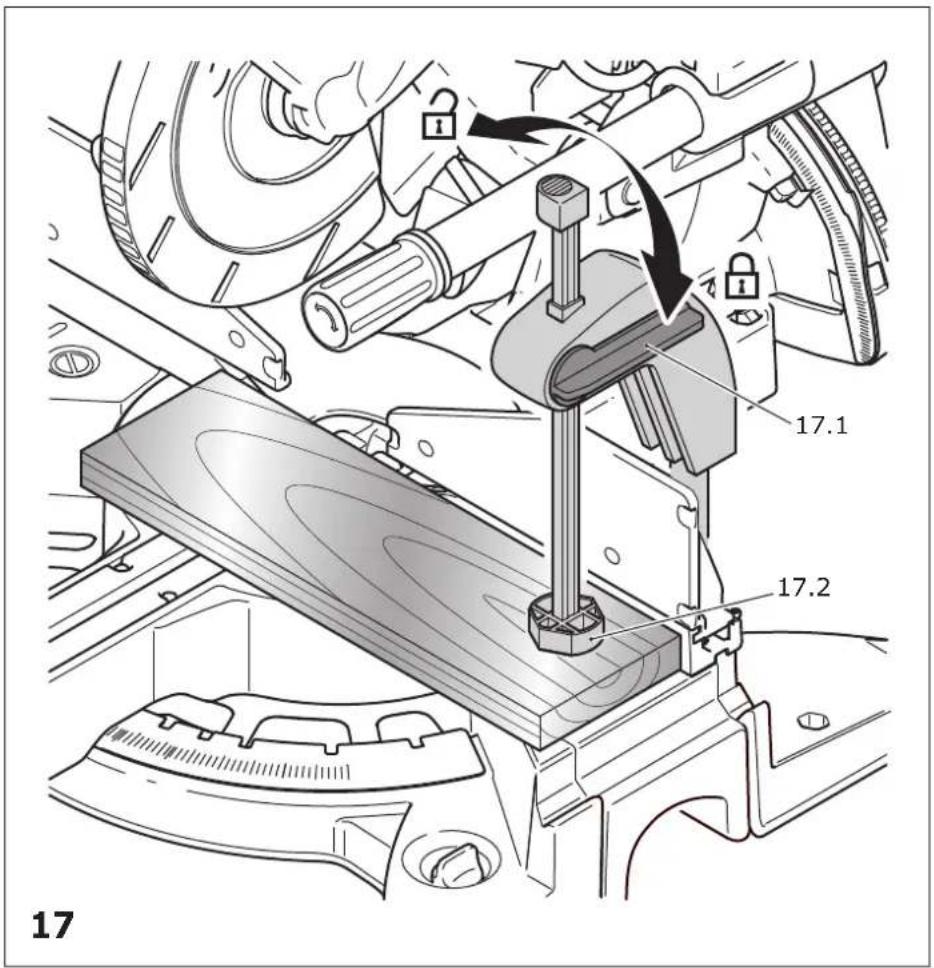
text_image
17 17.1 17.2 17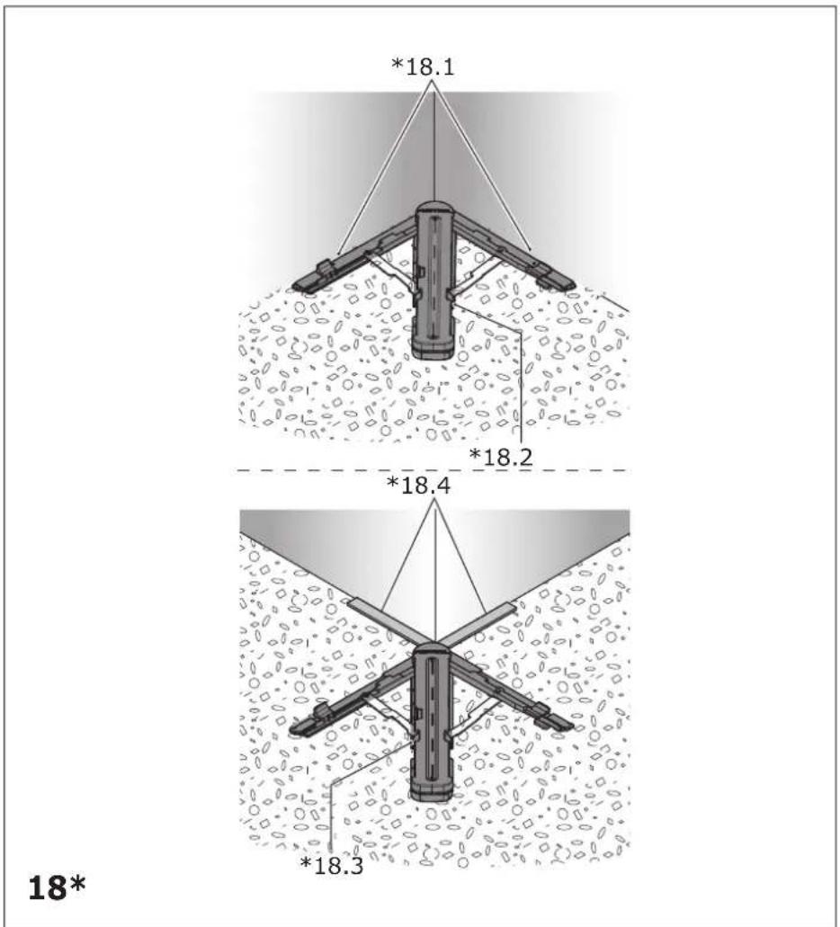
text_image
*18.1 *18.2 *18.4 *18.3 18*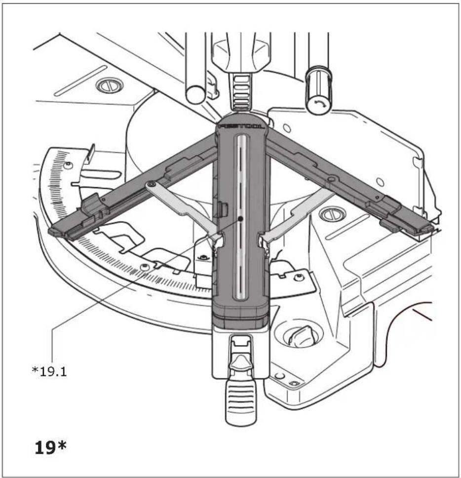
text_image
*19.1 19*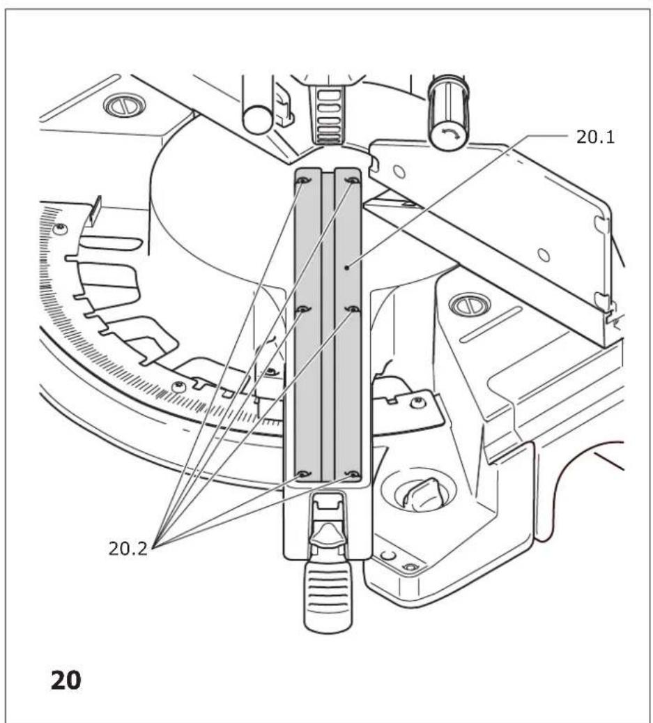
text_image
20.1 20.2 20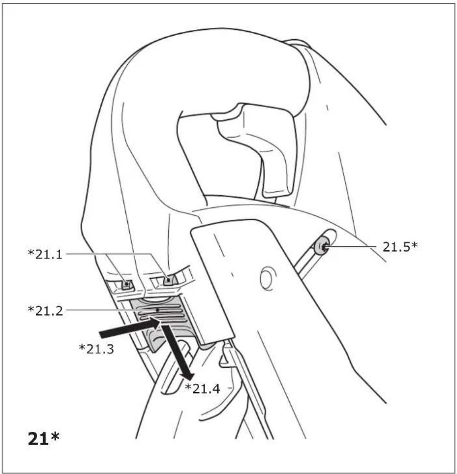
text_image
*21.1 *21.2 *21.3 *21.4 21.5* 21*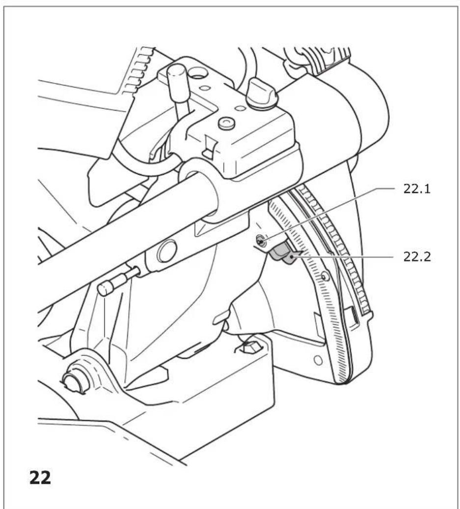
text_image
22 22.1 22.2 22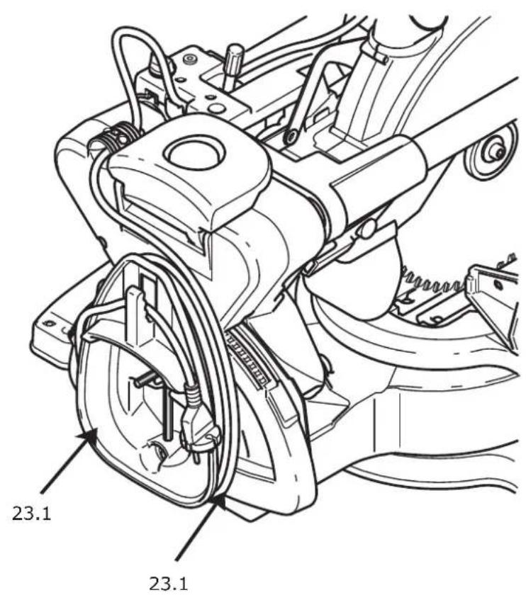
text_image
23.1 23.123
text_image
24.1 24.224