
RENOFIX RG 150 - Grinder FESTOOL - Free user manual and instructions
Find the device manual for free RENOFIX RG 150 FESTOOL in PDF.

| Product type | Grinder (restoration router) |
| Brand | Festool |
| Model | RENOFIX RG 150 |
| Weight | 5.9 kg |
| Tool diameter | 150 mm |
| Nominal voltage | 220 – 240 V~ |
| Mains frequency | 50 / 60 Hz |
| Rated input power | 1600 W |
| Speed under load | 1000 – 2200 min⁻¹ |
| Protection class | II (double insulation) |
| Main functions | Scraping of plaster, paint, adhesive residues; sanding of concrete; removal of formwork overruns; leveling of cement screeds |
| Prescribed use | Dry machining with powerful extraction |
| Speed preselection | Electronic, 6 steps from 1000 to 2200 rpm |
| Constant electronics | Maintains speed under load |
| Overload protection | Electronic and thermal |
| Extraction connection | Diameter 36 mm |
| Adjustable abrasion depth | 0 to 10 mm |
| Balancer | Suspension ring for cable |
| Floor guidance system | Optional (BG-RG 150) |
| Sound pressure level | 87 dB(A) |
| Sound power level | 100 dB(A) |
| Vibration emission (milling) | 4.0 m/s² |
| Vibration emission (grinding) | 2.6 m/s² |
| Regular maintenance | Clean cooling vents, replace worn carbon brushes, clean extraction flange |
| Spare parts | Use only original Festool parts |
| Repairs | Entrust to a Festool authorized workshop |
| Disposal | Do not dispose with household waste; recycle according to directives |
Frequently Asked Questions - RENOFIX RG 150 FESTOOL
User questions about RENOFIX RG 150 FESTOOL
0 question about this device. Answer the ones you know or ask your own.
Ask a new question about this device
Download the instructions for your Grinder in PDF format for free! Find your manual RENOFIX RG 150 - FESTOOL and take your electronic device back in hand. On this page are published all the documents necessary for the use of your device. RENOFIX RG 150 by FESTOOL.
USER MANUAL RENOFIX RG 150 FESTOOL
natural_image
Close-up of a mechanical device with a circular component and textured surface (no visible text or symbols)1
2a
2b
5
7
6
D
Renovation Cutter RG 150 E - original instruction
1 Symbols

Double insulation

Warning of general danger

Risk of electric shock

Use protective goggles!

Wear ear protection!

Use protective gloves!

Read the instructions

Not to be included in municipal refuse
i Advice or tip
2 Technical data
| Nominal voltage 220 – 240 V~ | |
| Mains frequency 50/60 Hz | |
| Power input 1600 W | |
| Speed under load 1000 – 2200 rpm | |
| Tool diameter 150 mm | |
| Weight | 5.9 |
| Protection class II / | |
3 Prescribed usage
The grinder is designed for the removal of plaster, screed, tiles and remains of carpet adhesive from concrete surfaces, the removal of shuttering projections and for flattening screed surfaces in the building trade.
The grinder must only be used for dry processing and combined with a powerful extraction system.
The user shall be liable for any damage resulting from non-specified use.
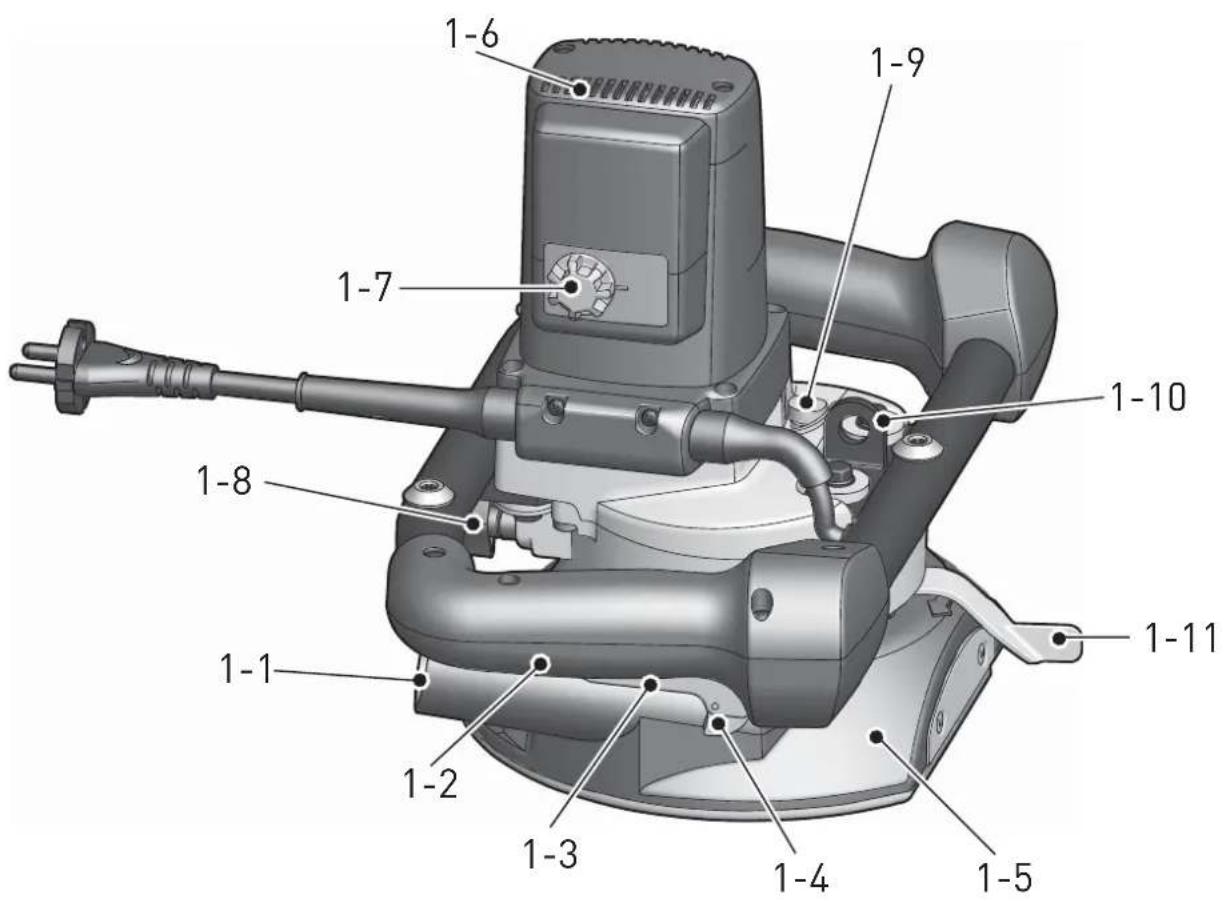
4 Control Elements
[1-1] Extraction connector
[1-2] Handles
[1-3] Switches
[1-4] Safety button
[1-5] Suction hood/base plate
[1-6] Vent openings
[1-7] Speed selection thumbwheel
[1-8] Longing screw
[1-9] Locking button
[1-10] Lifting eye for balancer
[1-11] Material removal depth adjustment lever Accessories that are illustrated or described here are not always included in the scope of delivery.
The specified illustrations can be found at the beginning of the operating instructions.
5 Notes on Safety Prevention
5.1 General safety instructions

WARNING! Read all safety warnings, instructions, illustrations and specifications provided with this power tool. Failure
to follow all instructions listed below may result in electric shock, fire and/or serious injury.
Save all warnings and instructions for future reference.
The term „power tool“ in the warnings refers to your mains-operated (corded) power tool or battery-operated (cordless) power tool.
5.2 Safety instructions for all operations
Safety Warnings Common for grinding, surface grinding or grinding with wire brush:
a) This power tool is intended to function as a surface grinder or a cutter with a cutter head. Read all safety warnings, instructions, illustrations and specifications provided with this power tool. Failure to follow all instructions listed below may result in electric shock, fire and/or serious injury.
b) Operations such as polishing, cutting or abrasive cutting are not recommended to be performed with this power tool. Operations for which the power tool was not designed may create a hazard and cause personal injury.
c) Do not use accessories which are not specifically designed and recommended by the tool manufacturer. Just because the accessory can be attached to your power tool, it does not assure safe operation.
d) The rated speed of the accessory must be at least equal to the maximum speed marked on the power tool. Accessories running faster than their rated speed can break and fly apart.
e) The outside diameter and the thickness of your accessory must be within the capacity
rating of your power tool. Incorrectly sized accessories cannot be adequately guarded or controlled.
f) The arbour size of wheels, fl anges, backing pads or any other accessory must properly fit the spindle of the power tool. Accessories with arbour holes that do not match the mounting hardware of the power tool will run out of balance, vibrate excessively and may cause loss of control.
g) Do not use a damaged accessory. Before each use inspect the accessory such as ABRASIV wheels for chips and cracks, backing pad for cracks, tear or excess wear, wire brush for loose or cracked wires. If power tool or accessory is dropped, inspect for damage or install an undamaged accessory. After inspecting and installing an accessory, position yourself and bystanders away from the plane of the rotating accessory and run the power tool at maximum no-load speed for one minute. Damaged accessories will normally break apart during this test time.
h) Wear personal protective equipment. Depending on application, use face shield, safety goggles or safety glasses. As appropriate, wear dust mask, hearing protectors, gloves and workshop apron capable of stopping small ABRASIV or workpiece fragments. The eye protection must be capable of stopping fl ying debris generated by various operations. The dust mask or respirator must be capable of fl ltrating particles generated by your operation. Prolonged exposure to high intensity noise may cause hearing loss.
i) Keep bystanders a safe distance away from work area. Anyone entering the work area must wear personal protective equipment. Fragments of workpiece or of a broken accessory may fly away and cause injury beyond immediate area of operation.
j) Hold power tool by insulated gripping surfaces only, when performing an operation where the cutting accessory may contact hidden wiring or its own cord. Cutting accessory contacting a "live" wire may make exposed metal parts of the power tool "live" and shock the operator.
k) Position the cord clear of the spinning accessory. If you lose control, the cord may be cut or snagged and your hand or arm may be pulled into the spinning accessory.
1) Never lay the power tool down until the accessory has come to a complete stop. The spin-
ning accessory may grab the surface and pull the power tool out of your control.
m) Do not run the power tool while carrying it at your side. Accidental contact with the spinning accessory could snag your clothing, pulling the accessory into your body.
n) Regularly clean the power tool's air vents. The motor's fan will draw the dust inside the housing and excessive accumulation of powdered metal may cause electrical hazards.
o) Do not operate the power tool near fl ammable materials. Sparks could ignite these materials.
p) Do not use accessories that require liquid coolants. Using water or other liquid coolants may result in electrocution or shock.
Further safety instructions for all operations Kickback and Related Warnings
Kickback is a sudden reaction to a pinched or snagged rotating wheel, backing pad, brush or any other accessory. Pinching or snagging causes rapid stalling of the rotating accessory which in turn causes the uncontrolled power tool to be forced in the direction opposite of the accessory's rotation at the point of the binding.
For example, if an ABRASIV wheel is snagged or pinched by the workpiece, the edge of the wheel that is entering into the pinch point can dig into the surface of the material causing the wheel to climb out or kick out. The wheel may either jump toward or away from the operator, depending on direction of the wheel's movement at the point of pinching. ABRASIV wheels may also break under these conditions.
Kickback is the result of power tool misuse and/or incorrect operating procedures or conditions and can be avoided by taking proper precautions as given below.
a) Maintain a firm grip on the power tool and position your body and arm to allow you to resist kickback forces. Always use auxiliary handle, if provided, for maximum control over kickback or torque reaction during start-up. The operator can control torque reactions or kickback forces, if proper precautions are taken.
b) Never place your hand near the rotating accessory. Accessory may kickback over your hand.
c) Do not position your body in the area where power tool will move if kickback occurs. Kick-back will propel the tool in direction opposite to the wheel's movement at the point of snagging.
d) Use special care when working corners, sharp
edges etc. Avoid bouncing and snagging the accessory. Corners, sharp edges or bouncing have a tendency to snag the rotating accessory and cause loss of control or kickback.
e) Do not attach a saw chain woodcarving blade or toothed saw blade. Such blades create frequent kickback and loss of control.
Additional safety instructions for grinding and cutting
Safety Warnings Specific for Grinding and ABRASIV Cutting-Off Operations:
a) Use only wheel types that are recommended for your power tool and the specific guard designed for the selected wheel. Wheels for which the power tool was not designed cannot be adequately guarded and are unsafe.
b) The guard must be securely attached to the power tool and positioned for maximum safety, so the least amount of wheel is exposed towards the operator. The guard helps to protect operator from broken wheel fragments and accidental contact with wheel.
c) Wheels must be used only for recommended applications. For example: do not grind with the side of cut-off wheel. ABRASIV cut-off wheels are intended for peripheral grinding, side forces applied to these wheels may cause them to shatter.
d) Always use undamaged wheel fl anges that are of correct size and shape for your selected wheel. Proper wheel fl anges support the wheel thus reducing the possibility of wheel breakage. Flanges for cut-off wheels may be different from grinding wheel fl anges.
e) Do not use worn down wheels from larger power tools. Wheel intended for larger power tool is not suitable for the higher speed of a smaller tool and may burst.
Additional safety instructions for wire brushing operations
Safety Warnings Specific for Wire Brushing Operations:
a) Be aware that wire bristles are thrown by the brush even during ordinary operation. Do not overstress the wires by applying excessive load to the brush. The wire bristles can easily penetrate light clothing and/or skin.
b) If the use of a guard is recommended for wire brushing, do not allow any interference of the wire wheel or brush with the guard. Wire wheel or brush may expand in diameter due to work load and centrifugal forces.
Further safety instructions
- The machine may not be used in damp and wet spaces, outdoor when it is rainy, foggy or snowy or in the explosive environment.
- Before use always inspect the fl exible lead and the plug. Have the defects repaired by a specialist repair shop.
- Outside the premise use only approved extension leads and cable connections.
- Apply the machine to the material only when switched on.
- Do not carry the machine by the lead.
- Do not work on a ladder.
- When operating the tool, use protective gloves and tough footwear.
- When operating the tool, use goggles and ear protectors.
- The dust generated during work is harmful to health. When operating the tool, use the dust extraction system and the respirator.
- Materials containing asbestos can only be processed by qualified individuals. Comply with the safety regulations that apply in your country.
- Flexible power supply cable always route from the tool backwards.
- Only use milling rings recommended by the manufacturer.
- Plug in the flexible power supply cable's plug into the wall socket when the machine is off.
- Make yourself sure whether the material that is going to be machined does not contain electric, water or gas lines – an injury could occur.
- Do not mill over metal objects, nails or screws.
- The machine is not allowed to be operated by a person under 16 years of age.
- Only for AS/NZS: The tool shall always be supplied via residual current device with a rated residual current of 30 mA or less.
5.3 Emission levels
Levels determined in accordance with EN 60 745 are typically:
Sound pressure level L_PA = 89 dB (A)
Noise level L_WA = 100 dB (A)
Uncertainty K = 3 dB


CAUTION
Operating noise
Damage to hearing
▶ Use ear protection!
Vibration emission value a_h (vector sum for three directions) and uncertainty K measured in accordance with EN 60 745:
Milling with milling head
$$ a _ {h} = 4. 0 \mathrm{m} / \mathrm{s} ^ {2} $$
$$ K = 1. 5 \mathrm{m} / \mathrm{s} $$
Grinding with grinding
$$ a _ {h} = 2. 6 \mathrm{m} / \mathrm{s} ^ {2} $$
wheel K = 1.5 m/s
The specified emissions values (vibration, noise) - are used to compare machines.
- They are also used for making preliminary estimates regarding vibration and noise loads during operation.
- They represent the primary applications of the power tool.
Increase possible for other applications, with other insertion tools or if not maintained adequately. Take note of idling and downtimes of machine!.
6 Activation

WARNING
Risk of accident if the machine is operated using unauthorised voltages or frequencies.
The mains voltage and the frequency of the power source must correspond with the specifications on the machine's name plate.
▶ In North America, only Festool machines with the voltage specifications 120 V/60 Hz may be used.
6.1 Switching on and off
Press the safety button [1-4] forwards to unlock the switch lever [1-3].
Actuate the switch lever [1-3] at the same time, which then starts up the machine. Release the lever again to bring the machine to a standstill.
Continuous operation
Press the safety button [1-4] forwards to unlock the switch lever [1-3].
Actuate the switch lever [1-3] at the same time to push the safety button [1-4] forwards as far
as the stop.
Continuous operation is interrupted by actuating the switching lever [1-3] again and releasing it.
6.2 Motor electronics
Starting current limitation
The electronically controlled smooth start-up ensures that the grinder starts up jolt-free. Thanks to starting current limitation of the grinder, 10 A fusing is suffi cient.
Electronic speed selection
The selection thumbwheel [1-7] is used to set the desired speeds – even during machine operation:
Level 1: 1000 rpm Level 4: 1700 rpm
Level 2: 1300 rpm Level 5: 2000 rpm
Level 3: 1500 rpm Level 6: 2200 rpm
The required speeds depend on the material to be ground. We recommend that you check this by means of a practical test (see Application table). With a high machine load, set the thumbwheel [1-7] to the edge position (Level 6).
After a long period of work at low speeds, allow the grinder to tick over for a further 3 minutes at maximum speed so that the motor can cool down.
Constant Electronics
The selected motor speeds are maintained at a constant level by the electronics. This guarantees a constant working feed and uniform material removal.
Electronic overload protection
In the event of extreme machine overloading, the motor is protected by the electronics against damage. For re-starting, the device must be first switched off and again switched on.
Thermal overload protection
To protect against overheating under extreme, continuous loads, the motor is switched over to cooling mode by the safety electronics when a critical temperature is reached. The grinder cannot be loaded; it runs a reduced speeds. After a cooling time of approx. 3 – 5 minutes, the machine can be operated again at full load. With grinders at service temperature, the thermal protection reacts earlier accordingly.
7 Usage


WARNING
Risk of accident, electric shock
▶ Always pull the plug out of the socket before performing any type of work on the machine.
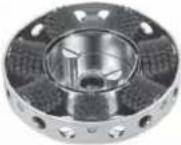
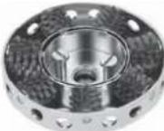
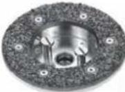
7.1 Selection of the tool head
Different cutter and grinding heads are available to match the usage and area of application. A suitable cutter head must be used to achieve optimum work results – see table on page 21. The speed selection data contained in the application table are recommended values and should be tested through practical tests.
7.2 Tool head change


CAUTION
Always wear protective gloves when working with the tool head.
The maximum permissible speeds of the tool used must at least match the maximum speeds of the machine.
① The tool head must not vibrate or be unbalanced; otherwise it has to be replaced.
① Only use original Festool tool heads.
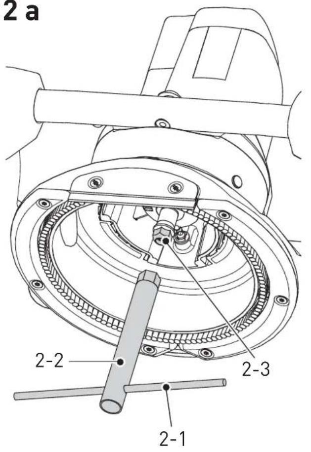
7.3 Inserting tool head
▶ Select the suitable tool head on the basis of usage and area of application (see Application table).
▶ Place the grinder on a flat, firm base (e.g. work bench).
▶ Insert pin [2-1] through the opening in the socket wrench [2-2] and unscrew clamping nut [2-3].
▶ Mount tool head [2-4] on the spindle [2-5]. Make sure the position of the spring [2-6] is correct; it must not slip out.
▶ Press in spindle locking button [1-9]. The locking button must only be pressed in with the spindle at a standstill and the grinder switched off.
▶ Turn the spindle until the locking button engages.
▶ Fully tighten clamping nut [2-3] with the socket wrench [2-2].

CAUTION
Turn the tool head by hand to check the true running.
Ensure that all screws are correctly tightened.
Never leave a tool wrench inserted.
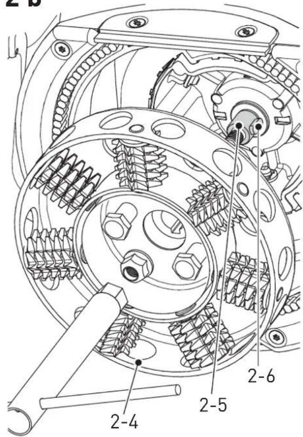
7.4 Removing tool head

CAUTION
The tool head can become very hot during the work process.
Allow the tool head to cool down before replacing it.
▶ Press in spindle locking button [1-9]. The locking button must only be pressed in with the spindle at a standstill and the grinder switched off.
▶ Turn the spindle until the locking button engages.
▶ Unscrew clamping nut with socket wrench.
▶ Mount extractor [3-1] and release tool head by turning hand screw clockwise. As soon as the tool head is released, it can be removed.
7.5 Adjusting material removal depth
Release the locking screw on the suction hood [1-8]. The grinding depth, or material removal dimension, can be adjusted by turning the material removal adjustment lever [1-11] between 0 and 10 mm.
Turning to left = higher grinding depth
Turning to right = lower grinding depth
The setting for the grinding depth depends on the material to be processed and the tool used.
7.6 Changing tools
Changing grinding wheels
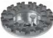
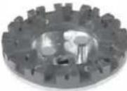
Reduced material removal quality is caused by tool wear. The cutter heads are provided with change wheels, which permit cutter heads to be reused following wheel replacement.
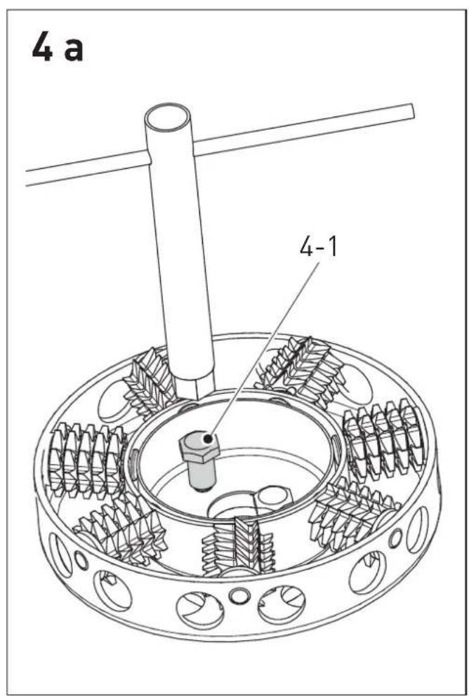
▶ Place the removed cutter head on a flat, firm base.
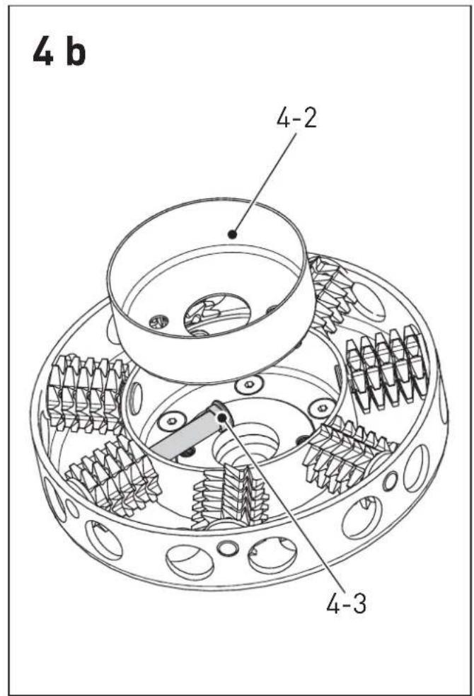
▶ Release stud [4-1] with pipe socket wrench and remove it. Remove the inner ring [4-2].
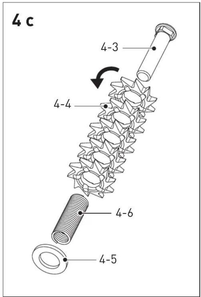
▶ Withdraw bearing pin [4-3]. Replace grinding wheels [4-4], bushes [4-6] and shims [4-5] with new ones from the replacement set.
▶ Mount 5 grinding wheels [4-4] and shim [4-5] on the bush [4-6]. These 7 groups must be reset in the cutter head such that the shim is the nearest to the outer edge of the cutter head – Fig. [4c].
▶ Insert bearing pin [4-3] through the openings in the cutter head back into the bushes [4-6].
- Secure bearing pin [4-3] by inserting the inner ring [4-2].
Screw in stud [4-1] and use pipe socket wrench
to tighten it to a torque of 7 Nm.
- With the grinding wheels with "flat-form teeth, ensure the wheels are correctly aligned – Fig. [4c].

CAUTION
Before the tool head is mounted, check the true running of the grinding wheels by turning them manually.
Changing grinding discs
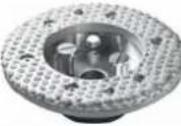
Reduced material removal quality is caused by tool wear. Grinding heads can be reused after changing the grinding disc.
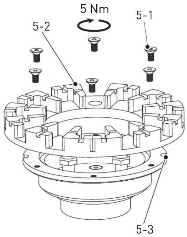
▶ Place the removed cutter head [5-3] on a clean and fl at base.
▶ Release screws [5-1] and remove them.
▶ Clean clamping surfaces of grinding head.
▶ Replace grinding disc [5-2] with a new one and secure again with screws [5-1] .
▶ Tighten to a tightening torque of 5 Nm.
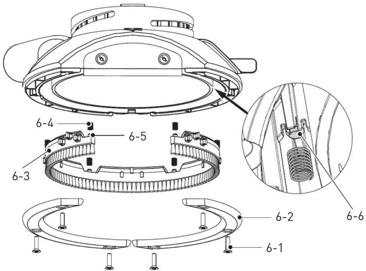
Changing lower brush
If the lower brush [6-3] is excessively worn, its protective function will be impaired. It therefore has to be changed.
▶ Remove screws [6-1] and take off slide plates [6-2] .
▶ Remove lower brush [6-3] including springs [6-4].
▶ Fit springs [6-4] on bolts [6-5] of new lower brush and insert brush. When doing this, ensure that the springs fall onto the suction hood bolt [6-6].
▶ Place slide plates [6-2] in position and secure with screws [6-1].
▶ Check mechanism for correct function.
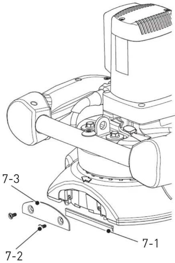
Changing front brush
If the front brush [7-1] is excessively worn, its protective function will be impaired. It therefore has to be changed.
▶ Release screws [7-2] and guard panel [7-3].
▶ Replace front brush [7-1] with a new one, place panel in position and secure with screws [7-2].
7.7 Dust extraction
Dust created during work can be harmful to health, combustible or explosive.
The machine must be connected to a suitable extraction system (vacuum cleaner). The vacuum cleaner must be suitable for the processed material. If the vacuumed dust is particularly harmful
to health, carcinogenic or dry, a special vacuum "cleaner from the Festool range must be used.
The extraction connector [1-1] is suitable for an extraction hose with dia. 36 mm.
To guarantee optimum extraction and a long service life of the cutting and grinding tools, the extraction channels must be cleaned regularly.
7.8 Balancer
The grinding is provided with a lifting eye [1-10] for using a balancer.
This weight relief makes work easier, e.g. on facades and walls.
7.9 Surface guidance system BG-RG 150
The surface guidance system allows the machine to be guided in upright position on the floor. The integrated weight guarantees optimum contact pressure. The rollers facilitate transport of the complete device between the different places of use.
8 Work instructions
With the machine switched on, place it on the surface of the workpiece and move it in longitudinal and transverse direction in a parallel or circular motion.
The material removal capacity is determined, above all, by a suitably selected tool and the setting of the material removal depth.
An excessive increase in pressure does not results in increase material removal, but rather leads to increased wear of the machine and grinding tools. During the work process, ensure that the extractor hose is not kinked or damaged.
Faulty extraction leads to increased dust contamination and wear of the grinding tool.

CAUTION
During work, check whether the grinding wheels continuously turn freely about their axes. If they do not, remove them from the tool head.
9 Service and maintenance

WARNING
Risk of accident, electric shock
▶ Always pull the plug out of the socket before performing any type of work on the machine.
▶ All maintenance and repair work which requires the motor housing to be opened, must only be carried out by an authorised service workshop.
- Wrapped electric tools can be stored in a dry place without heating, with temperatures not lower than -5^ . Unwrapped electric tools can only be stored in dry places with temperatures not lower than +5^ , without sudden changes in the temperature.
- To ensure the airflow is sufficient, cooling openings of the motor must be always clean and free.
- The machine is equipped with special self-disconnecting brushes. When the brushes are worn, the power supply is automatically disconnected, and the machine is stopped.
- If the suction fl ange height adjustment system does not operate smoothly, the fl ange must be removed and cleaned.

Customer service and repair. Only through manufacturer or service workshops: Please find the nearest
address at: www.festool.net/service

Use only original Festool spare parts! Order No. at:
www.festool.net/service
10 Environment
Do not throw the power tool in your household waste! Dispose of the machine, accessories and packaging at an environmentally-responsible recycling centre! Observe the valid national regulations.
EU only: In accordance with European Directive on waste electrical and electronic equipment and implementation in national law, used electric power tools must be collected separately and handed in for environmentally friendly recycling.
Information on REACH:
www.festool.com/reach
11 EU Declaration of Conformity
Renovation Cutter Serial no.
RG 150 E 768916, 768884
Year of CE mark: 2013
We declare under sole responsibility that this product comply with all relevant requirements of the following directives, norms or normative documents:
2006/42/EG, 2004/108/EG (until 19.04.2016), 2014/30/EU (from 20.04.2016), 2011/65/EU,
EN 60745-1:2009, EN 60745-2-3:2011+A2:2013,
EN 55014-1:2006+A1:2009+A2:2011, EN 55014-2:
1997+Corrigendum 1997+A1:2001+A2:2008, EN 61000-3-2:2006+A1:2009+A2:2009, EN 61000-3-3:2013.
Festool GmbH
Wertstr. 20, D-73240 Wendlingen

Head of Research, Development and Technical Documentation
2015-03-02
12 Selection of the tool head
| Tool head Fitting | Application Thumbwheel | ||
 | Carbide grinding wheels with “split-form” teeth, set of 35 SZ-RG 150 | Removal of plaster for facing, remains of tile adhesive and synthetic resin plaster | 4-6 |
 | Carbide grinding wheels with “fl at-form” teeth, set of 35 FZ-RG 150 | Remove of soft plaster, fresh concrete, remains of concrete and protective coatings | 4-6 |
 | Diamond disc DIA-HARD 150 | Removal of hard materials, e.g. concrete with a strength higher than C10, hard screed | 6 |
 | Diamond disc DIA-ABRA-SIV 150 | Removal of soft materials with higher removal rates, e.g. fresh concrete, tile adhesive, plaster for facing, sandstone | 6 |
 | Diamond disc DIA UNI 150 | Universal application, e.g. paints (on concrete, plaster, wood), adhesives, plaster for facing | 5-6 |
 | Carbide disc HW-150/SC F | for elastic coatings, protective coatings, latex-based and oil-based paints, plaster and porous concrete | 2-3 |

i Information,astuce
$$ L _ {W A} = 1 0 0 \mathrm{dB(A)} $$
Osäkerhet K = 3 dB


OBS
[1-10] Opphengelement for opphengtau
[1-11] Spake for dybdeinnstilling
7.5 Dybdeinnstilling
$$ L _ {W A} = 1 0 0 \mathrm{dB(A)} $$


- D
- Renovation Cutter RG 150 E - original instruction
- Symbols
- Technical data
- Prescribed usage
- Control Elements
- Notes on Safety Prevention
- General safety instructions
- Safety instructions for all operations
- Further safety instructions for all operations Kickback and Related Warnings
- Additional safety instructions for grinding and cutting
- Safety Warnings Specific for Grinding and ABRASIV Cutting-Off Operations:
- Additional safety instructions for wire brushing operations
- Safety Warnings Specific for Wire Brushing Operations:
- Further safety instructions
- Emission levels
- CAUTION
- Operating noise
- Damage to hearing
- Activation
- WARNING
- Risk of accident if the machine is operated using unauthorised voltages or frequencies.
- Switching on and off
- Continuous operation
- Motor electronics
- Starting current limitation
- Electronic speed selection
- Constant Electronics
- Electronic overload protection
- Thermal overload protection
- Usage
- Risk of accident, electric shock
- Selection of the tool head
- Tool head change
- Always wear protective gloves when working with the tool head.
- Inserting tool head
- Removing tool head
- Adjusting material removal depth
- Changing tools
- Changing grinding wheels
- Before the tool head is mounted, check the true running of the grinding wheels by turning them manually.
- Changing grinding discs
- Changing lower brush
- Changing front brush
- Dust extraction
- Balancer
- Surface guidance system BG-RG 150
- Work instructions
- Service and maintenance
- Environment
- Information on REACH:
- EU Declaration of Conformity
- Renovation Cutter Serial no.
- Festool GmbH
- OBS
- Dybdeinnstilling
Brand : FESTOOL
Model : RENOFIX RG 150
Category : Grinder