PSA 15 A1 - Wall hose reel PARKSIDE - Free user manual and instructions
Find the device manual for free PSA 15 A1 PARKSIDE in PDF.
| Product type | Wall-mounted hose reel |
| Brand | Parkside |
| Model | PSA 15 A1 |
| Dimensions (approx.) | 30 x 20 x 20 cm |
| Weight (approx.) | 2.5 kg |
| Power supply | Manual (no electricity) |
| Hose length | 15 m |
| Max. water pressure | Standard (suitable for domestic taps) |
| Main functions | Automatic reel with anti-return device, 180° swivel, integrated water stop |
| Material | Resistant plastic, steel (spring) |
| Care and cleaning | Clean with a damp cloth; store frost-free in winter |
| Safety | Do not direct the spray at people or animals; do not drink the water; do not leave children unattended |
| Spare parts and repairability | Use only original spare parts |
| Delivery contents | Wall mount, hose housing, 15 m garden hose, spray nozzle, connection hose, tap parts, wall plugs and screws |
| Warranty | In accordance with applicable legislation (see instruction manual) |
Frequently Asked Questions - PSA 15 A1 PARKSIDE
User questions about PSA 15 A1 PARKSIDE
0 question about this device. Answer the ones you know or ask your own.
Ask a new question about this device
Download the instructions for your Wall hose reel in PDF format for free! Find your manual PSA 15 A1 - PARKSIDE and take your electronic device back in hand. On this page are published all the documents necessary for the use of your device. PSA 15 A1 by PARKSIDE.
USER MANUAL PSA 15 A1 PARKSIDE
natural_image
Close-up of a black plastic electrical plug with attached cable, shown in black and white (no text or symbols visible)WAND-SCHLAUCHAUFROLLER / WALL-MOUNTED HOSE REEL / ENROULEUR DE TUYAU MURAL PSA 15 A1
DE AT CH
WALL-MOUNTED HOSE REEL
Quick start guide
NL BE
WAND-SLANGOPWIKKELAAR
Kortehandleiding
CZ
NÁSTĚNNÝ NAVÍJEČ HADICE
Krátkýnávod
ES
TAMBORPORTAMANGUERA DE PARED
Guíarápida
natural_image
Diagram of a mechanical device with directional arrows indicating motion or force (no text or symbols)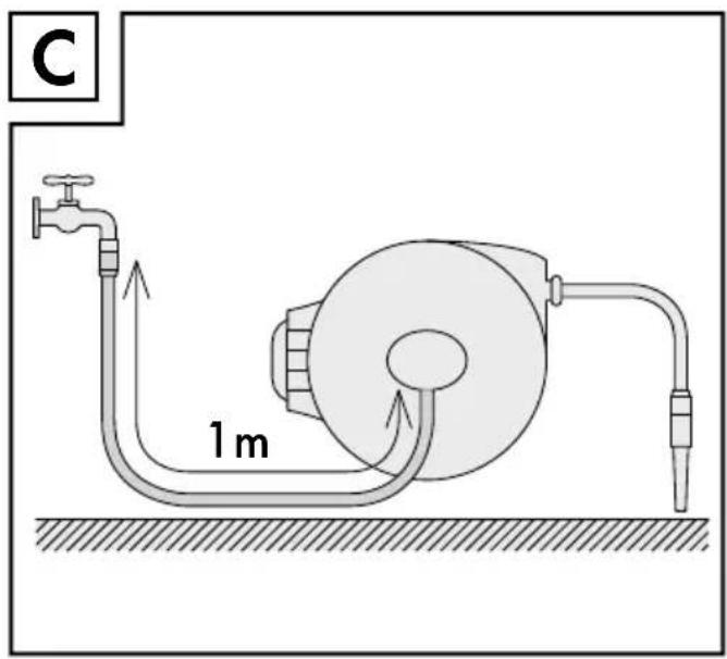
text_image
C 1 m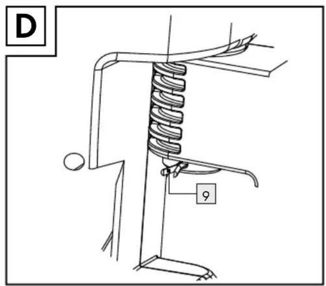
text_image
D 9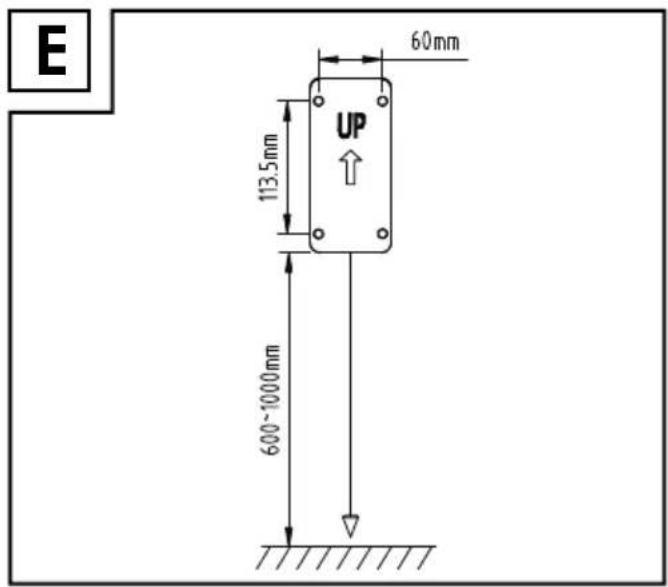
text_image
E 60mm 113.5mm UP 600~1000mm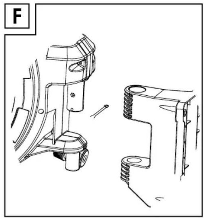
natural_image
Technical line drawing of mechanical components including a bracket, spring, and housing (no text or symbols)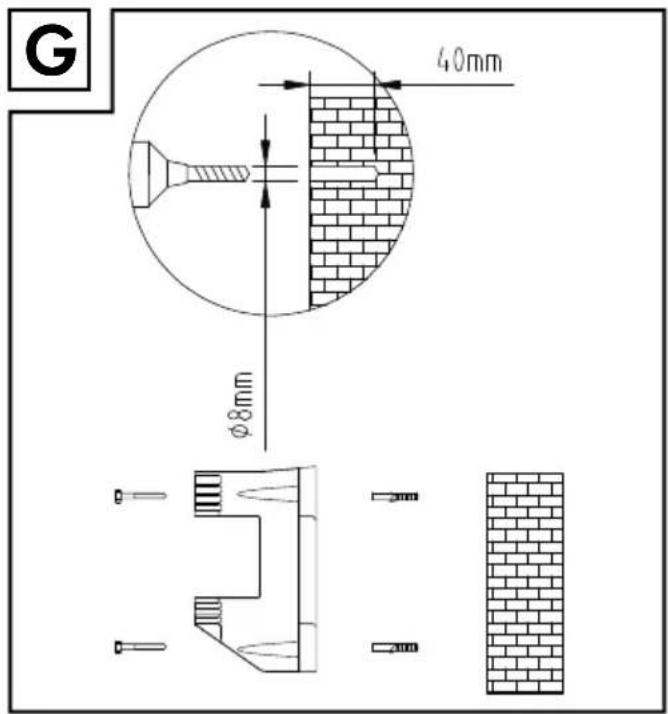
text_image
G 40mm Ø8mm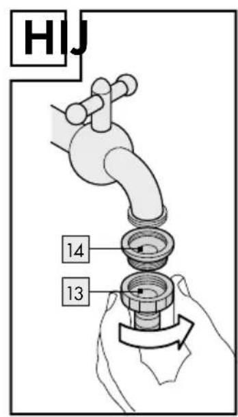
text_image
HIJ 14 13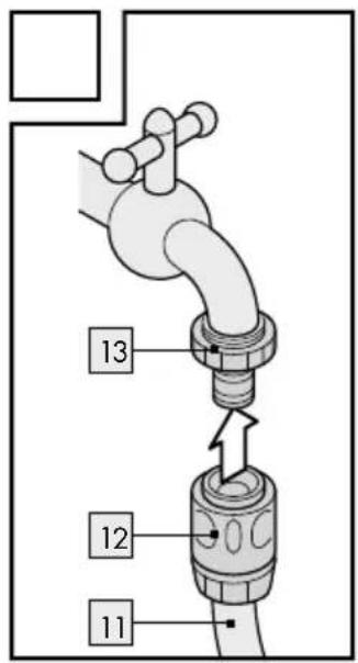
text_image
13 12 11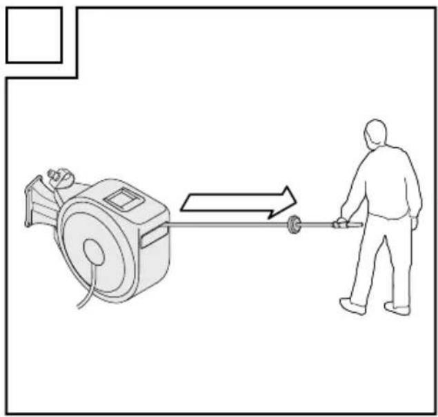
natural_image
Line drawing of a person pulling a cart from a machine to another person (no text or symbols)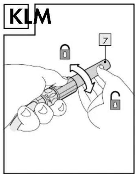
text_image
KLM 7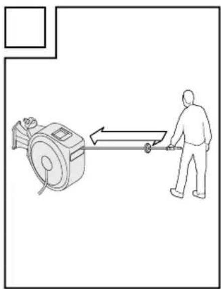
natural_image
Line drawing of a person pulling a cart from a mechanical device (no text or symbols)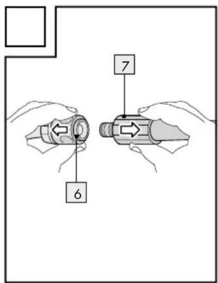
text_image
6 71 Einleitung

Wall-Mounted Hose Reel
1 Introduction

This quick start guide is a fixed part of the original operating instructions. Store this together with the original operating instructions in a safe place. When passing this product on to others, please be sure to include all documentation. Read the original operating instructions before use, and pay particular attention to the safety instructions included therein.

text_image
PDF ONLINE www.lidl-service.comScan the QR code or download the complete original operating instructions at www.lidl-service.com.
1.1 Parts description / Scope of delivery
1 wall bracket
2 1 carrying handle
3 1 hose box
4 1 limit stop
5 1 irrigation hose
6 1 hose connector with water stop for spray nozzle
7 1 spray nozzle
8 4 wall plugs (6 x 40 mm)
9 1 split pin
10 4 screws (6 x 50 mm)
11 1 connection hose
12 1 hose connector for tap
13 1 tap connector
14 1 reducer
Assembly instructions and instructions for use
2 Safety notes
KEEP ALL SAFETY INFORMATION AND INSTRUCTIONS FOR FUTURE REFERENCE!

text_image
WARNING! DANGER TO LIFEAND RISK OF ACCIDENTS FOR INFANTS AND CHIL-
DREN! Do not allow children to play with the product or to carry out cleaning or user maintenance unsupervised.
■ Never leave the product unattended whilst in use.
- Keep children away from the work area during assembly. This product has screws and other small parts. These could lead to suffocation if they are swallowed or inhaled.
- Do not allow children to play with the packaging film or parts of the packaging, otherwise they may become entangled in it whilst playing or swallow parts and suffocate.
■ Make sure that you do not damage any power lines during installation.
■ Never aim the water jet at electrical equipment.
■ Never aim the water jet at people or animals.
■ Make sure that all parts are undamaged and correctly assembled.
■ Regularly check the water pressure to prevent water leaking under high pressure and causing injury. Do not aim the water jet at people or animals.
■ Never drink the water that you transport with the product. The product is not suitable for potable water. The product is intended for carrying water from installations in fixed locations. You cannot use it to transport other liquids.
■ Only lay the unravelled hose flat on the ground. Avoid loops which stand up. Loops are trip hazards and can cause accidents.
- Do not leave the hose to re-ravel itself. Carefully guide it back into the housing.
- Do not let go of the hose unless the automatic stop function is engaged.
■ Danger of slipping! When the ground is wet, you can easily
slip on the ground and injure yourself. Ensure that the ground near the product is kept as dry as possible.
■ Turn the tap off when the product is not in use.
■ Make sure that you do not damage any cables, power lines and water pipes during installation.
Check the installation area with a cable detector before drilling.
■ To avoid frost damage, take the product off the wall in winter and store it dry.
- Do not take the hose around corners or edges and do not move it along pointed or sharp-edged objects. The resulting damage may lead to leakages.
- Do not put the hose in areas where vehicles are known to drive. Driving over the hose may cause it to split.
- Do not open the housing of the product. The springs are pre-loaded, they can spring back.
■ Never remove any screws from parts of the housing.
■ Ensure that the hose does not re-wind itself. Doing so may result in damage.
■ Never block the hose end with your fingers or other objects during use.
■ Installation must be performed by a professional.
■ Discontinue using the product if the plastic parts are cracked or deformed. Always replace damaged parts with genuine spare parts.
3 Before installation
■ Make sure that you do not damage any cables, power lines and water pipes during installation. Check the installation area with a cable detector before drilling.
☐ Remove the product from the packaging.
☐ Check that the delivery contents are complete (see fig. A).
- Check to see if the product or the individual parts are visibly damaged. If this is the case, do not use the product.
3.1 Selecting the installation location
- Choose a stable weight-bearing installation location.
- Be aware of the weight of the product including the water in the hose (see chapter „Technical data“).
☐ Choose an installation location where the full 180^ swivel range of the hose box 3 can be used (see fig. B).
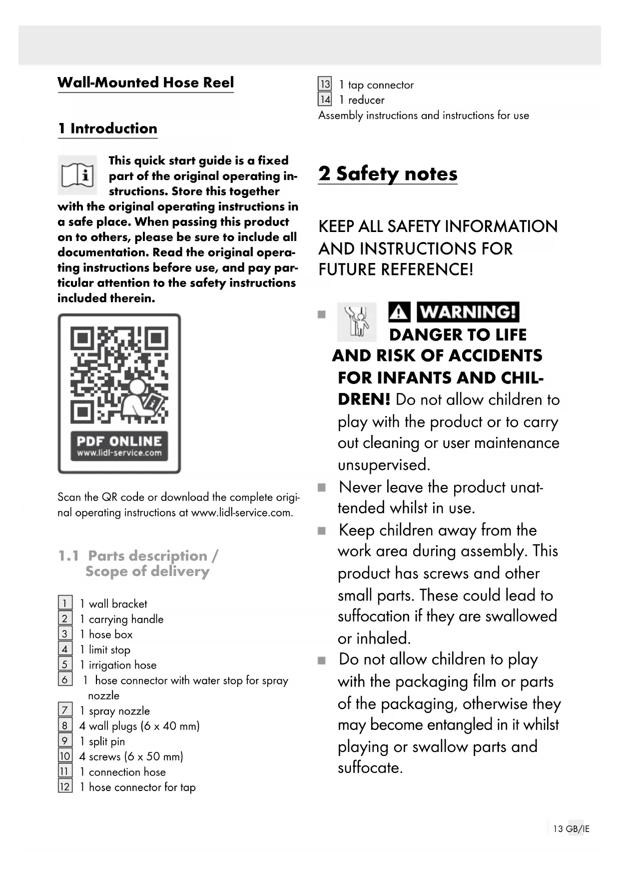
☐ Measure the distance to the tap so that the connection hose 11 can be connected with slack (see fig. C).
3.2 Selecting the installation material
☐ For installation on a concrete or brick wall, use the accompanying screws 10 and wall plugs
8 (see fig. G). These are only suitable for concrete or brick walls.
☐ You will need a screwdriver with a head width of 13 mm to screw in the screws ^10 . This is not included.
☐ Use suitable screws and wall plugs for installation on other materials or plaster thicker than 10 mm. Ask a specialist retailer about wall plugs and screws suitable for the respective wall structure.
4 Installation
☐ Mark the drill holes at the specified height and drill four holes (see fig. E).
☐ Insert the wall plugs 8 into the drilled holes.
☐ Mount the wall bracket 1 using the screws 10. The wall bracket 1 must be attached vertically. Ensure that the wall bracket 1 is attached in the direction of the arrow (the arrow must be pointing upwards). For concrete walls and brickwork, follow figure G.
☐ Mount the hose box 3 on the wall bracket 1 (see fig. F). Hold the hose box 3 by the handle 2. Guide the hose box 3 into the wall bracket 1 until the axle holes line up. Secure the hose and wall bracket with the split pin supplied 9 (see fig. D). The bend in the open end of the split pin 9 ensures that the split pin 9 does not reopen.
Connect the tap connector to the tap (see fig. H). Turn the reducer 14 towards the tap connector 13 in accordance with the size of the tap's connecting thread.
☐ Connect the hose piece 12 and the connection hose 11 to the tap connector (see fig. I). Please note that it will click audibly.
☐ Connect the spray nozzle 7 to the hose connector with the water stop 6. Please note that it will click audibly. Ensure that the spray nozzle 7 is closed (see fig. K).
The product is ready to use.
5 Operation
5.11 Unravelling the hose
☐ Pull the irrigation hose 5 out of the hose box 3 to the desired length (see fig. J).
☐ Allow the hose to follow. The irrigation hose 5 will go back a short distance until it is held by the retraction block.
Open the tap. Ensure that the spray nozzle is closed.
Open the spray nozzle 7 by turning it to the right (see fig. K).
The red marking on the hose signifies that you are coming to the end of the hose. From here, the hose can only be pulled out a few more cm.
5.2 Re-ravelling the hose
Risk of injury and damage! If the irrigation hose is not guided, the spring tension of the automated ravelling system can cause it to spin around and lead to injury and property damage.
■ Always guide the irrigation hose by hand. Ensure that no other people are nearby when re-ravelling.
■ Never reach inside of the housing.
☐ Close the spray nozzle 7 by turning it to the left (see fig. K).
Close the tap.
Open the spray nozzle 7 to release the water pressure. Turn the spray nozzle 7 to the right to do so. Close the spray nozzle 7 again by turning it to the left.
☐ Hold the irrigation hose 5 by the spray nozzle 7. Pull briefly on the irrigation hose 5 to release the retraction block. Guide the irrigation hose 5 by hand while it automatically rolls up to the limit stop 4 into the hose box 3 (see fig. L).
□ Swivel the hose box 3 towards the wall to save space (see fig. B).