
Diamant Plus S - Air conditioner FERROLI - Free user manual and instructions
Find the device manual for free Diamant Plus S FERROLI in PDF.
| Brand | Ferroli |
| Model | Diamant Plus S |
| Product type | Split air conditioner (air/air) |
| Refrigerant | R32 (flammable) |
| Power supply | 220-240 V / 50 Hz |
| Remote control | With LCD screen, range 8 m |
| Operating modes | Auto, Cool, Dehumidification, Heat, Fan |
| Fan speed | Auto, Low, Medium, High |
| Special functions | ECO, Turbo, Self Clean, Sleep, Follow Me, Swing, Timer, Shortcut |
| Temperature range | 17 to 30 °C (not in Fan mode) |
| Timer | Delayed start and stop, combined (up to 24 h) |
| Error display | Codes E0 to F5, P0 to P4, EC, etc. |
| Emergency button | On indoor unit: Auto, Forced Cool, Off |
| Auto restart | Automatic restart after power failure |
| Louver position memory | Yes |
| Filter cleaning | Recommended monthly; reminder after 240 h and 2880 h |
| Outdoor unit maintenance | Periodic cleaning of grilles and fins |
| Safety | Overload protection, mandatory grounding |
| Warranty | 2 years (under conditions) |
| Flammable refrigerant | R32 – follow safety instructions |
Frequently Asked Questions - Diamant Plus S FERROLI
User questions about Diamant Plus S FERROLI
0 question about this device. Answer the ones you know or ask your own.
Ask a new question about this device
Download the instructions for your Air conditioner in PDF format for free! Find your manual Diamant Plus S - FERROLI and take your electronic device back in hand. On this page are published all the documents necessary for the use of your device. Diamant Plus S by FERROLI.
USER MANUAL Diamant Plus S FERROLI
Domestic air conditioner
natural_image
Illustration of a hand installing or removing a remote control panel into two views (no text or symbols present)fig. 3 -
flowchart
graph TD
    A["MODE ON/OFF"] --> B["FAN"]
    B --> C["Upward Arrow"]
    B --> D["Downward Arrow"]
fig. 5 -
natural_image
Diagram of a cylindrical device with directional arrows indicating flow or movement (no text or symbols)fig. 7 -

natural_image
Technical line drawing of a wall-mounted air conditioner unit with internal cooling fins and wiring (no text or symbols)fig. 8 -
2.9 IMPOSTAZIONE DEL TIMER
fig. 10 -
fig. 11 -
flowchart
graph TD
    A["Start"] --> B["Off"]
    B --> C["Set"]
    C --> D["Stop"]
    style A fill:#f9f,stroke:#333
    style B fill:#ccf,stroke:#333
    style C fill:#cfc,stroke:#333
    note1["2 hours later after setting"] -.-> A
    note2["5 hours later after setting"] -.-> C
fig. 12 -
DISPLAY UNITA' INTERNA
natural_image
Technical line drawing of an air conditioner unit showing internal components and a close-up view of the internal structure (no text or labels)fig. 14 -
natural_image
Diagram of a hand pressing a button on an open computer chassis panel (no text or symbols visible)fig. 15 -

natural_image
Diagram showing a hand pressing down on a textured panel with a black arrow indicating direction (no text or symbols)fig. 16 -

natural_image
Diagram showing hands installing a brick wall with a block being removed (no text or symbols)fig. 17 -

natural_image
Diagram showing a water tank with a faucet above it, no text or symbols presentfig. 18 -
2.16 PULIZIA DELL'UNITÀ INTERNA
1.1 CONSIGNMENT OF THE MACHINE....21
1.2 FOREWORD 21
1.3 PRESENTATION OF THE UNIT....21
1.4 DECLARATION OF CONFORMITY 21
1.5 REMOTE CONTROL....22
Button description....22
Indicators on LCD "fig. 2 -" 23
2. STARTING 24
2.1 ADVICE ON HOW TO USE THE REMOTE CONTROL....24
2.2 INSERTING/REPLACING THE BATTERIES 24
2.3 POWERING THE AIR CONDITIONER 24
2.4 HOW TO USE THE BUTTONS 25
2.5 Other operations mode....26
2.6 FAILURE DISPLAY....27
2.7 AUTO MODE....28
2.8 ADJUSTING THE OUTPUT AIR....28
2.9 TIMER SETTING 29
Setting the auto-start time (TIMER ON) ....29
Setting the auto-off timer (TIMER OFF) ....29
2.10 TIMER FUNCTION ....30
"TIMER ON" (funzionamento con accensione automatica)....30
"TIMER OFF" (Auto-off Operation) 30
TIMER ON TIMER OFF (Simultaneous setting for turning on and turnin ogg the air conditioner) ....31
INDOOR UNIT DISPLAY....32
2.11 INTERNAL UNIT EMERGENCY BUTTON....33
2.12 AUTO-RESTART FUNCTION....33
2.13 FLAP POSITION MEMORY 33
2.14 SWITCHING OFF AND SHUT DOWN 33
2.15 CLEANING THE FILTERS OF THE WALL MODELS UNIT 34
2.16 CLEANING THE INDOOR UNIT 34
2.17 CLEANING THE OUTDOOR UNIT 34
3. SAFETY AND POLLUTION 35
3.1 GENERAL CONSIDERATIONS ....35
4. SERVICE AND SPARE PARTS 35
4.1 TROUBLE SHOOTING 35
4.2 SAFETY REGULATIONS....36
1. GENERAL SPECIFICATIONS
1.1 CONSIGNMENT OF THE MACHINE
As soon as the machine is consigned, it is essential for the user to make sure that he has received all the items indicated on the consignment note and that the machine has not been damaged during transport. If damage is discovered, allow the forwarding agent to ascertain its entity and also inform our seller. Only in this way will you be able to receive the missing items or reimbursement of damages within the shortest possible time.
1.2 FOREWORD
This machine has been designed and built for air conditioning purposes alone and must only be used for that purpose. Even the best of machines can only operate properly if they are correctly used and kept fully efficient. Please read this instruction manual carefully and consult it should difficulties arise when the machine is used. Remember that our after sales-service, organized in collaboration with our dealers, is always at your disposal if advice or interventions are required.
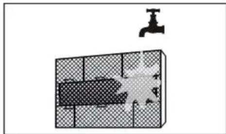
1.3 PRESENTATION OF THE UNIT
Air conditioners/split type air conditioners must be connected to an outdoor unit. This model range can be coupled to both outdoor units like the Mono-Split type, coupled to only one indoor unit, or the Multi-Split type that can be coupled to two or more indoor units. The series is available in the heat pump version with R32.

Appliance filled with flammable gas R32.
Please notice that the unit is filled with flammable gas R32. Inappropriate treatment of the unit involves the risk of severe damages of people and material. Details to this refrigerant are found in section "SERVICE AND SPARE PARTS" a pagina 35.
1.4 DECLARATION OF CONFORMITY
The manufacturer declares that the machines described in this instruction manual meet the requirements of the following directives and subsequent modifications.
- Low voltage directive 2014/35/EU;
• Electromagnetic compatibility directive 2014/30/EU;
• RAEE directive 2012/19/EU;
• RoHS directive 2011/65/EU;
• ErP directive 2009/125/CE
• Energy labelling regulation EU 2017/1369;
It conforms to what is stated in the legislation
• EN 60335-2-40

1.5 REMOTE CONTROL
The remote control ("fig. 1 -") has a series of keys and a display which visualizes all the activated functions and the various parameters the user and installer need in order to correctly use the unit itself.
Button description
- "ON/OFF" key to turn the air conditioner on and off.
- "MODE" key to select the operating mode: AUTO - COOL-DRY - FAN - HEAT:
- AUTO: The conditioner automatically sets the suitable operating mode (HEAT, DRY, FAN, COOL) depending on room temperature.
- COOL: The unit begins to operate if the set temperature is lower than that of the room.
- DRY for Dehumidify
- FAN: the unit get the air automatically circulating in the room.
-
HEAT: The unit begins to operate if the set temperature is higher than that of the room.
-
"FAN" key to set the fan speed by the choosing Automatic - low - mid - high
-
"SLEEP" key, overnight button to set/cancel the Sleep mode regardless of the operating mode of the conditioner.
-
"ECO" button. Activates the "energy saving" mode.
-
"TURBO" button to enable/disable the rapid cooling mode.
-
"SELF CLEAN" button allows you to activate or deactivate the SELF CLEAN to the drying of the internal coil in order to prevent the formation of odors.
-
"LED" button to enable/disable the display of the unit.
-
"FOLLOW ME" button Push this button to initiate the Follow Me feature, the remote display is actual temperature at its location. The remote control will send this signal to the air conditioner every 3 minutes interval until press the Follow Me button again. The air conditioner will cancel the Follow Me feature automatically if it does not receive the signal during any 7 minute interval.
-
"SWING" buttons activate/deactivate automatic movement of air flap.
-
SWING 📋 buttons . Not available.
-
"TIMER" button. Activates the TIMER function for delayed activation and delayed shutdown of the unit.
-
"SHORTCUT" button. Memorizes the current settings and enables to recall them rapidly.
-
"TEMP" button. For setting "TEMP" (▲) it sets the increase, (▼) sets its decline. If you activate the TIMER function enables you to set the time for switching off desired.

fig. 1 -
Indicators on LCD "fig. 2 -"

fig. 2 -
-
ON/OFF display Displayed by pressing the ON/OFF button. Press the ON/OFF button again to remove If present this icon indicates that you have set the power-up.
-
Transmission Indicator. This transmission indicator lights when remote controller transmits signals to the indoor unit.
-
Mode display. Displays the current operation mode. Including auto( Cooling & heating models only ), fan( ) and back to auto( ).
-
TIMER display:
-
TIMER ON" - Displayed when TIMER ON time is set.
-
TIMER OFF" - Displayed when TIMER OFF time is set.
-
Icons display:
-
FOLLOW ME icon. It is displayed when the "FOLLOW ME" function is activated.
- CLEAN icon. It is displayed when the "CLEAN" function is active.
-
SLEEP icon. It is displayed when the "SLEEP" operating mode is activated.
-
Fan speed display. Display area where fan speed setting is displayed. The fan speed can be automatic (✿ AUTO) or adjusted at different intervals: low (*), medium (*)) ... max (*)). The fan speed is forced to "AUTO" when the operating mode is "AUTO" or "DRY".
- Display Temperature / Timer / Fan Speed. Area in which the temperature setting is indicated (17 °C \~ 30 °C, increments of 1 °C) .. If the "FOLLOW ME" mode is activated, after a few seconds the temperature detected by the remote control is indicated and at the same time the "Set Temp" icon disappears. By setting the "FAN" operating mode, the temperature is not displayed. When activating the "TIMER" functions, timer setting is shown for a few seconds in place of the temperature setting.
- LOW BATTERY icon. Displayed when the charge of remote control batteries is low.
- KEYBOARD LOCKED icon. Displayed when the remote control keypad is locked.
- ECO icon. Displayed when the "ECO" function is activated
2. STARTING
2.1 ADVICE ON HOW TO USE THE REMOTE CONTROL
Comply with the following instructions to correctly use the remote control:
- Remove the battery if the remote control is not going to be used for a long period of time.
- When used, direct the remote control towards the signal receiver of the interior unit (1).
- The remote control signal is received up to a distance of 8 meters.
- The signal must not be obstructed by any kind of object.
- Handle the remote control with care.
- The signal could be disturbed by a fast-acting lamp, a fluorescent lamp of the inverter type or a mobile phone.
- The remote control should not be left in a place where it could be exposed to direct sunlight, near a stove or another heat source.
N.B. The batteries described in point 1 must be kept in a safe place, well away from children's reach.
2.2 INSERTING/REPLACING THE BATTERIES
To insert/replace batteries, proceed as follows "fig. 3 -":
- Remove the cover (1).
-
Remove the discharged batteries and insert the new ones (2), making sure that they are positioned as shown in the diagram in the battery housing.
-
Fit the cover (3) back in place.
N.B.: Remove the batteries from the remote control when the air conditioner is not going to be used for a long period of time, must be kept in a safe place, well away from children's reach. To safeguard the environment and the safety of persons, always dispose of old batteries in the specific containers.

natural_image
Illustration of a hand installing or removing a remote control panel into two views (no text or symbols present)fig. 3 -
2.3 POWERING THE AIR CONDITIONER
Press the ON/OFF button ("fig. 4 -") to power the air conditioner. Remember that the liquid crystal display will always indicate the last operating mode and previously used functions. Comply with the instructions if you wish to change the operating mode of the system.

fig. 4 -
2.4 HOW TO USE THE BUTTONS
By pressing the "MODE" button ("fig. 5 -") it is possible to select the operating modes (Fig. 3) you prefer, choosing between the following ones: AUTO - COOL - DRY - HEAT - FAN.

flowchart
graph TD
    A["MODE"] --> B["ON/OFF"]
    B --> C["FAN"]
    C --> A
fig. 5 -
- AUTO Mode- Automatic: this function is selected by pressing the "MODE" button until the relative Symbol appears on the display. The conditioner automatically sets the suitable operating mode (COOL, DRY, HEAT, FAN) depending on room temperature. The temperature can be set within a range of 17^ C \~ 30^ C in 1^ C increments.
- COOL Mode- Cooling: this function is selected by pressing the "MODE" button until the relative Symbol appears on the display. The unit begins to operate if the set temperature is lower than that of the room. The temperature can be set within a range of 17^ C \~ 30^ C in 1^ C increments. In this operation mode, it is possible to set fan speed (high-medium-low-auto) by pushing the FAN button.
- DRY Mode - Dehumidifying: this function is selected by pressing the "MODE" button until the relative Symbol appears on the display. The unit will begin to operate in the cooling mode, and will quickly reach the required ambient temperature. Condensation may form on the delivery port if the "DRY" function is used for a long period of time (the fan seed isn't adjustable). The temperature can be set within a range of 17^ C \~ 30^ C in 1^ C increments.
- HEAT Mode- Heating: this function is selected by pressing the "MODE" button until the relative Symbol appears on the display. The unit begins to operate if the set temperature is higher than that of the room. The temperature can be set within a range of 17^ C \~ 30^ C in 1^ C increments. In this operation mode, it is possible to set fan speed (high-medium-low-auto) by pushing the FAN button.
- FAN Mode- Ventilation: this function is selected by pressing the "MODE" button until the relative Symbol appears on the display and the unit get the air automatically circulating in the room. When operating in ventilation alone can not set a value for set point.
2.5 OTHER OPERATIONS MODE
Some of the selected modes are indicated in the display while others are only implemented by the unit without any indication.

fig. 6 -
- ECO mode (part. 1 "fig. 6 -") (the indoor unit displays shows the "E-C-O" letters one by one, followed by the temperature setpoint). The "energy saving" mode in only available in COOL mode by pressing the "ECO" button. If the temperature setpoint is lower than 24^ , by activating the "ECO" mode the temperature setpoint is automatically set to 24^ and fan speed to "Auto" to save energy. If the temperature setpoint is higher than 24^ , by activating the "ECO" mode the temperature setpoint does not change and fan speed is set to "Auto". To stop the "ECO" mode, either press the "ECO" button, or choose another operation mode, or choose a temperature setpoint lower than 24^
- SLEEP function (part.2 "fig. 6 -"). Keep pressed the "ECO" button for 2 seconds to activate the "SLEEP" mode is indicated by the symbol on the display. The set point temperature will be increased (in cooling operation "COOL") or decreases (in hot operation "HEAT") 1 °C at predetermined intervals to a maximum of 2 °C. SLEEP function stops automatically after 8 hours and the unit will continue operation by keeping the last setpoint. The function is not available in "FAN" and "DRY" modes.
- FOLLOW ME function (part.3 "fig. 6 -"). Activated in HEAT - AUTO - COOL mode operation. The remote control will send this signal to the air conditioner every 3 minutes interval until press the Follow Me button again. The air conditioner will cancel the Follow Me feature automatically if it does not receive the signal during any 7 minute interval.
- SELF CLEAN mode (nothing is shown on the remote, the indoor unit display shows the text "SC"). Available in COOL – DRY modes. By pressing the "SELF CLEAN" button, VENTILATION-HEATING-VENTILATION modes are activated in sequence to prevent any residual condensation from forming mold and bad smells. At the end of the cycle the unit switches off automatically. If the "SELF CLEAN" button is pressed during the cleaning cycle, this will stop the cycle and turn off the unit.
- TURBO mode (nothing is shown on the remote, the indoor unit display shows the text "ON" for 3 seconds when the mode is activated, "OF" for 3 seconds when the mode is deactivated). This operation mode is only available in cool and heat mode. It forces the unit to reach the desired setpoint as soon as possible.
- SWING mode (nothing is shown on the remote, the indoor unit display shows the text "ON" for 3 seconds when the mode is activated, "OF" for 3 seconds when the mode is deactivated). The automatic movement of the air flap is activated by pressing the "SWING" button. Keep pushed the "SWING" button (part. 9 "fig. 1 -") to activate automatic movement of the flap. Push once the "SWING" (part. 9 "fig. 1 -") button to adjust the position of the flap by 6^ .
- 8°C Heat mode (not shown on the display of remote control, the display of the indoor unit shows the text "FP") In HEAT mode with a temperature setpoint at 16°C, press the "-" button twice within one second to activate the 8°C heat operating mode. The temperature setpoint is set at 8 °C to prevent frosting.
- Key lock. Pressing the "TURBO" (part. 5 "fig. 1 -") and "SELF CLEAN" (part. 6 "fig. 1 -") buttons simultaneously for one second activates / deactivates the remote control keypad lock.
- Shortcut Function. Memorizes the current settings and enables to recall them rapidly. Push the "SHORTCUT" (part. 12 "fig. 1 -") button for 2 seconds to save current settings. Push the "SHORTCUT" (part. 12 "fig. 1 -") button to recall the saved settings.
2.6 FAILURE DISPLAY
When there is failure in the unit operation the code of failure will be displayed. The following table describes the error messages represented by the code displayed on the Indoor Display. It should be noted that some error codes are specific only in conjunction with unit single Split or Multi-Split
Table. 1 - Error
| Error Code on Display | Error description Notes | |
| E0 / EH 00 Indoor unit EEPROM parameter error Alarm | ||
| E1 / EL 01 Indoor / outdoor unit communication error Alarm | ||
| E2 / EH 02 | Zero-crossing signal detection error (for some models) Alarm | |
| E3 / EH 03 | The indoor fan speed is operating outside of the normal range Alarm | |
| E4 / EH 60 | Indoor room temperature sensor T1 is in open circuit or has short circuited Alarm | |
| E5 / EH 61 | Evaporator coil temperature sensor T2 is in open circuit or has short circuited Alarm | |
| E7 / EH 0b Indoor PCB / Display board communication error Alarm | ||
| EC / EL 0C Refrigerant leak detected Alarm | ||
| F0 / PC 08 | Current overload protection Alarm | |
| F1 / EC 53 | Outdoor room temperature sensor T4 is in open circuit or has short circuited Alarm | |
| F2 / EC 52 | Condenser coil temperature sensor T3 is in open circuit or has short circuited Alarm | |
| F3 / EC 54 | Compressor discharge temperature sensor TP is in open circuit or has short circuited Alarm | |
| F4 / EC 51 | Outdoor unit EEPROM parameter error Alarm | |
| F5 / EC 07 | The outdoor fan speed is operating outside of the normal range (for some models) Alarm | |
| P0 / PC 00 | IPM malfunction or IGBT over-strong current protection Temporary protection | |
| P1 / PC 01 | Over voltage or over low voltage protection | Temporary protection |
| P2 / PC 02 | High temperature protection of IPM module Temporary protection | |
| P4 / PC 04 | Inverter compressor drive error | Temporary protection |
Some errors are reported by the display but do not generate the shutdown of the unit. It 'should report in every case to Technical Assistance. Some alarm can be caused by the poor maintenance of the units. It is recommended to perform this procedure before ask for the Technical Assistance.
Note for Multi Split applications
In case of simultaneously operating mode requested, any incompatibility will be signaled by the symbol P5. The system generally ensures priority to units set to Heat.
Table. 2 - Compatibility Table
(1): unit 1 turns off
(2): unit 2 does not switch on
2.7 AUTO MODE
During the AUTO mode, the unit automatically selects HEAT, FAN, COOL based on the ambient temperature
AUTO mode activation:
First select the AUTO on the remote control using the MODE key. Then select the desired set point temperature. The mode of operation will depend on the difference, positive or negative, between the set temperature and the ambient temperature. If this difference cannot exceed the unit is activated only in ventilation mode.
Notes to the AUTO mode
- In "AUTO" mode, the air conditioner can automatically switch between the modes of cooling, heating and ventilation by detecting the difference between the actual temperature and the set temperature on the remote control.
- In "AUTO" mode, you can select the fan speed, which is adjusted automatically.
- If you think that the "AUTO" mode does not ensure the necessary comfort, you can manually select the desired mode.
2.8 ADJUSTING THE OUTPUT AIR
When you turn the flap assumes a preset angle. It's possible to adjust automatically the vertical direction of the air while the horizontal adjustment is necessary to intervene manually.
Vertical Adjustment
To adjust the vertical air flow direction ("fig. 7 -") of the indoor unit press the "SWING" (part. 9 "fig. 1 -").
By holding down the key "SWING" (part. 9 "fig. 1 -") for 2 sec, the air flap continues to move, mixing the air in the environment.
By pressing the "SWING" (part. 9 "fig. 1 -") button, the air flap blocks and each time the "SWING" (part. 9 "fig. 1 -") button is pressed, the airflow direction is changed by an angle of 6^ .
Note: in "COOL" or "DRY" operating mode, it is not recommended to set the flap in vertical position for too long to avoid the accumulation of condensate drops
In "COOL" or "HEAT" operating mode, it is not recommended to position the flap in a vertical position as the low air flow can reduce the performance of the unit.
Do not change the position of the flap manually. If this happens, switch the unit off and switch it off for a few seconds to reset the positioning of the deflector.
Horizontal Adjustment
To adjust the direction of the horizontal air flow ("fig. 8 -") must be operated manually by acting on the levers of the deflector

natural_image
Diagram of a cylindrical device with arrows indicating airflow or force direction (no text or symbols)fig. 7 -

natural_image
Technical line drawing of a wall-mounted air conditioner unit with internal cooling fins and wiring (no text or symbols)fig. 8 -
2.9 TIMER SETTING
Press the "TIMER" button once and then the "▲" or "▼" button to set the unit's automatic switch-on timer, or press the "TIMER" button twice and then the "+" or "-" button to set the switch-off time automatic unit.
Setting the auto-start time (TIMER ON)
- Press the "TIMER" button once. The LCD display on the remote control shows the "TIMER ON" icon and indicates the automatic switch-on time instead of the temperature. At this point it is possible to set the auto-start timer.
- Press the "▲" or "▼" button repeatedly to set the desired auto-start time. Each time the button is pressed, the time increases by 30 minutes between 0 and 10 hours, while the increase is one hour between 10 and 24 hours.
- Once the "TIMER" function has been set, a delay of three seconds occurs before the remote control transmits the signal to the air conditioner. Then, after about 2 more seconds, the temperature setpoint appears on the remote control LCD display again and the "TIMER ON" icon (ON) remains lit.
Setting the auto-off timer (TIMER OFF)
- Press the "TIMER" button twice. The LCD display on the remote control shows the "TIMER OFF" icon indicating the automatic switch-on time instead of the temperature. At this point it is possible to set the new automatic auto-off timer.
- Press the "▲" or "▼" button repeatedly to set the desired switch-off time. Each time the button is pressed, the time increases by 30 minutes between 0 and 10 hours, while the increase is one hour between 10 and 24 hours.
- Once the "TIMER" function has been set, a delay of three seconds occurs before the remote control transmits the signal to the air conditioner. Then, after about 2 more seconds, the temperature setpoint appears on the remote control LCD display again and the "TIMER OFF" icon (OFF) remains lit.

flowchart
graph TD
    A["MODE ON/OFF"] --> B["FAN"]
    B --> C["Timer"]
fig. 9 -
CAUTION
- When you select the timer operation, the remote controller automatically transmits the timer signal to the indoor unit for the specified time. Therefore, keep the remote controller in a location where it can transmit the signal to the indoor unit properly.
- The effective operation time set by the remote controller for the timer function is limited every 30 minutes.
2.10 TIMER FUNCTION
The TIMER ON feature is useful when you want the unit to turn on automatically before you return home. The air conditioner will automatically start operating at the set time.
Example to start the air conditioner in 6 hours.
- Press the TIMER button once, the turning on time, the signal "H" and the signal "TIMER ON" will be shown on the specific display area.
- Press the "▲" button to display "6:0H" on the display of the remote controller.
- Wait for 3 seconds and in the same display area will be shown the temperature again. The "TIMER ON" indicator remains on and this feature is activated.


fig. 10 -
"TIMER OFF" (Auto-off Operation)
The TIMER OFF feature is useful when you want the unit to turn off automatically after you go to bed. The air conditioner will stop automatically at the set time.
Example to turn off the air conditioner in 10 hours
- Press the TIMER button two times, the turning off time, the signal "H" and the signal "TIMER OFF" will be shown on the specific display area.
- Press the "▼" button to display "10H" on the display of the remote controller.
- Wait for 3 seconds and in the same display area will be shown the temperature again. The "TIMER OFF" indicator remains on and this feature is activated.


fig. 11 -
TIMER ON TIMER OFF (Simultaneous setting for turning on and turnin ogg the air conditioner)
"TIMER ON" → "TIMER OFF" (Turnerd Off → Turned On → Stopped)
This feature is useful when you want to start the air conditioner before you wake up and stop it after you leave the house.
Example: auto-on 2 hours after setting and auto-off 5 hours after setting
- Press the "TIMER" button once.
- Press the "▲" button to display 2.0H on the remote control display.
- After 3 seconds, the temperature will be shown again in the same area of the display. The "TIMER" signal remains lit to confirm that the feature has been activated.
- Press the "TIMER" button twice.
- Press the "▲" button to display 5.0H in the remote control display.
- After 3 seconds, the temperature will be shown again in the same area of the digital display. The "TIMER OFF" indicator remains lit to confirm that the feature has been activated
NOTE:
The timer setting (TIMER ON or TIMER OFF) that in sequence occurs directly after the set time will be activated first.

fig. 12 -
INDOOR UNIT DISPLAY
The meaning of the codes shown on the display of the indoor unit is described below ("fig. 7 -").

fig. 13 -
1. TEMPERATURE
In normal operating conditions, the display shows the temperature setpoint.
2. ERROR
In case of error, the display shows an error code as indicated in the table "ERROR DISPLAY".
3. ECO FUNCTION
By activating the "ECO" function, the "88" symbol lights up gradually showing the letters "E- - C - - O", followed by the temperature setpoint
4. TIMER ON/FUNCTION ACTIVATION
The display shows the text "ON" for 3 seconds when:
- a delayed start timer is activated ("TIMER ON")
- one of the following functions is activated: "SWING" or "TURBO"
5. TIMER OFF/FUNCTION DEACTIVATION
The display shows the text "OF" for 3 seconds when:
- a delayed shutdown timer is activated ("TIMER OFF")
- one of the following functions is deactivated: "SWING" or "TURBO"
6. DEFROST ACTIVATION
The display shows the text "dF" (defrost) when the outdoor unit performs a defrost cycle.
7. SELF CLEAN ACTIVATION
The display shows the text "SC" when the unit performs a battery drying cycle
8. PRE-HEATING FUNCTION ACTIVATION INDICATION
The display shows the text "cF" when the pre-heating function is active to avoid cold air flow. The function is only available in heating mode.
9. WIFI ACTIVATION
The display shows the symbol shown in "fig. 7 -", detail 1, when the unit is regularly connected to the wireless network for remote control.
10. REFRIGERANT LOSS
In "COOL" operating mode, the display shows the text "EC" if a refrigerant leak is detected.
11. ANTI-FREEZE MODE ACTIVATION
The display shows the text "FP" (frost protection) when the antifreeze function is activated, which allows to set a safety temperature of 8^ in the room. The function is only available in heating mode.
12. CLEAN FILTER OR FILTER REPLACEMENT
After 240 hours of use, the display shows the text "CL" for 15 seconds, as a reminder to clean the air filters, then the warning disappears.
After 2,880 hours of use, the display shows the text "nF" for 15 seconds, as a reminder to replace the air filters, then the warning disappears.
To reset the reminder, press the "LED" button 4 times or press the emergency button 3 times. If the reminder is not reset, it will appear again, as described above, when the unit is turned back on.
2.11 INTERNAL UNIT EMERGENCY BUTTON
To use the unit in manual mode ("fig. 8 -").
- Open the front panel of the unit and locate the "MANUAL BUTTON"
- Press the manual button once to activate the "AUTO" operating mode; the set-point is automatically set to 24^ C
- Press the manual button a second time to activate the "COOL" operating mode. The text "FC" (forced cooling) appears on the unit display
- Press the manual button a third time to turn off the unit
- Close the front panel

natural_image
Technical line drawing of an air conditioner unit showing internal structure and a close-up view of the component (no text or symbols)fig. 14 -
2.12 AUTO-RESTART FUNCTION
The unit is programmed to switch on automatically in the event of a power failure.
2.13 FLAP POSITION MEMORY
When turning on the unit, the flap direction is the same of the last use
2.14 SWITCHING OFF AND SHUT DOWN
To switch off the conditioner, press the "ON/OFF" button on the remote control. As soon as it is switched on, or when it is switched off and back on again, the compressor does not start working immediately but waits three minutes in order to protect the system. Before switching off the unit for a long period, keep it running for two or three hours in the cooling mode with the temperature set to 30°C. Then disconnect the power supply, clean the filters and remove the battery from the remote.
2.15 CLEANING THE FILTERS OF THE WALL MODELS UNIT
To ensure the appliance operates correctly, the air filter must be checked and cleaned periodically. To do so, proceed as follows:
- Remove the plug from the socket.
- Lift the front panel.
- Remove the filters by pushing up the central tabs until they free themselves from the retainer and slide them off downwards ("fig. 15 -" and "fig. 16 -")
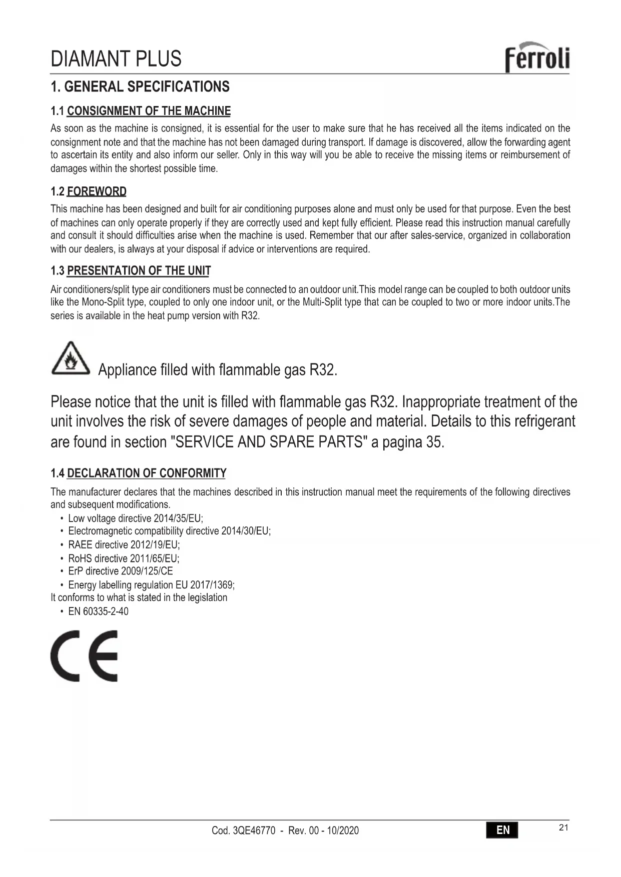
- Remove the air purifier filter on the back of the main filter ("fig. 17 -") and clean it with a vacuum cleaner
- Wash the main filters with water or clean them with a vacuum cleaner. Allow the filters to dry completely without exposure to direct sunlight.
- Reassemble everything in the initial position.
- Close the front panel of the unit and plug in the socket.
N.B. This operation must be performed at least once a month (the frequency of cleaning interventions varies according to the characteristics and of the dust present in the room to be conditioned)

natural_image
Diagram of a hand pressing a button on an open computer chassis panel (no text or symbols visible)fig. 15 -

natural_image
Diagram of a car interior with a hand placing a component into the window (no text or symbols visible)fig. 16 -

natural_image
Diagram showing hands installing a brick wall with a block being removed (no text or symbols)fig. 17 -

natural_image
Diagram showing a water tank with a faucet and a shaded interior area, no text or symbols present.fig. 18 -
2.16 CLEANING THE INDOOR UNIT
Proceed as follows to clean the interior unit :
- Clean with a damp cloth.
- Do not use direct jets of water to clean the unit or the electrical components could be damaged.
- Never use spirits or other corrosive substances to clean the unit
2.17 CLEANING THE OUTDOOR UNIT
- The exterior unit must be cleaned periodically and at the beginning of the season before starting the air conditioner.
- Clean the air intake and outlet gratings, removing any dirt that may obstruct the free circulation of air, being careful not to damage the fins of the condensing bank.
Note: When cleaning the rear grille be careful not to cut yourself on the fins of the condensing bank.
3. SAFETY AND POLLUTION
3.1 GENERAL CONSIDERATIONS
The machine has been designed to reduce risks to persons and to the environment in which it is installed, to the minimum. To eliminate residual hazards, it is therefore advisable to become as familiar as possible with the machine in order to avoid accidents that could cause injuries to persons and/or damage to the machine.
Consult the technical safety briefs available from coolant manufacturers for further information about the characteristics of the cooling fluid.
4. SERVICE AND SPARE PARTS
Ask the dealer where the appliance was purchased for the address of our nearest Service center or look in the Yellow Pages under the heading: "Air Conditioners" or "Boilers".
4.1 TROUBLE SHOOTING
The table below explains some of the faults that the electronic monitoring plant may detect and transmit to the user.
| Issue Cause Solution | ||
| The unit does not start by pressing ON/OFF button on the remote control | No power | Check that the power cord is properly plugged in the mains socket. Check that there is voltage in the mains socket. If the fault persists, call service. |
| The unit has a overload protection functions. The unit can be restored 3 minutes after being switched off. | Wait 3 minutes, then restart the unit. | |
| The indoor unit works properly while the outdoor unit remains off. | The outdoor unit is not powered Call service | |
| The unit works but does not cool. | The unit lacks refrigerant. Potential solenoid valve failure | Call service |
| The compressor operates for short periods and stops for a few minutes. | Unit partially lacks refrigerant charge. The outdoor unit heat exchanger is dirty. | Call service. Clean the outdoor unit heat exchanger as indicated in the section "Cleaning the outdoor unit" of the present manual. |
4.2 SAFETY REGULATIONS
Strictly comply with the following regulations to prevent injury to the operator or damage to the machine.
- The unit installation must be done according to the installation rules valid in your country.
- This installer's handbook, the user manual and the wiring diagrams are integral part of the machine. They must be kept with care and be ready to hand should the operators require them for consultation.
- Failure to comply with the instructions in this manual and inadequate installation of the conditioner may void the certificate of guarantee. Moreover, the Manufacturer shall not be liable for direct and/or indirect damages due to incorrect installation or for damages caused by conditioners installed by inexpert or unauthorized personnel.
• Work in a clean, uncluttered place when installing the equipment. - It is absolutely forbidden to touch moving parts or to move between the same.
- Before starting the conditioner, make sure that the various components and the entire system are in perfect and safe conditions.
- Strictly comply with the routine maintenance operations.
- Insist on genuine spare parts. Failure to do so will void the guarantee.
- Do not remove or tamper with the safety devices.
- Disconnect the electric power source before proceeding with any work on the machine.
- Do not place anything on the top part of the units.
- Do not push items through the protective fan grilles or allow objects to drop through.
• The bank surface is sharp. Do not touch it without protective gloves. - Carefully read the stickers on the machine, never cover them and replace them immediately should they be damaged.
- Do not use the machine in an explosive atmosphere.
• The power line must be regularly grounded. - If the power cable has been damaged, stop the machine if it is operating, and have the cable immediately replaced by an authorized technician.
• The machine must be stored at a temperature between -25°C and 55°C. - Use a powder extinguisher in the event of a fire outbreak. Do not use water.
- If the machine operates in an abnormal way, make sure that this does not depend on failure to carry out routine maintenance. Failing this, ask to have the machine checked by a specialized technician.
• If the outdoor unit must be dismantled, it is advisable to have the job done by an authorized technical service centre. - The machine must not be dumped if it is to be scrapped since it contains materials that must be recycled or disposed of by authorized centres.
- Do not wash the machine with direct or pressurized jets of water or with corrosive substances.
The Manufacturer and after-sales service network are at your disposal for prompt and accurate technical assistance and for anything else able to ensure the best operation and achieve the utmost efficiency from your machine.
1. CARACTERÍSTICAS GENERALES....38
natural_image
Illustration of a hand installing or removing a remote control panel into two views (no text or symbols present)fig. 3 -
2.3 ENCENDIDO DEL ACONDICIONADOR
flowchart
graph TD
    A["MODE ON/OFF"] --> B["FAN"]
    B --> C["Downward Arrow"]
    C --> D["Upward Arrow"]
fig. 5 -
natural_image
Diagram of a cylindrical device with a downward arrow indicating compression or disassembly (no text or symbols present)fig. 7 -
natural_image
Technical line drawing of a wall-mounted air conditioner unit with internal cooling fins and wiring (no text or symbols)fig. 8 -
fig. 10 -
fig. 11 -
fig. 12 -
natural_image
Technical line drawing of an air conditioner unit showing internal components and a close-up view of the internal structure (no text or symbols)fig. 14 -
natural_image
Diagram of a hand pressing down on a computer ventilation panel with an arrow indicating the press direction (no text or symbols present)fig. 15 -

natural_image
Diagram of a car interior with a hand holding a mesh panel and a black arrow pointing to the door (no text or symbols present)fig. 16 -

natural_image
Diagram showing hands installing a brick wall with a rectangular block on the left (no text or symbols)fig. 17 -

natural_image
Diagram showing a water tank with a faucet above it, no text or symbols presentfig. 18 -
2.16 LIMPIEZA DE LA UNIDAD INTERIOR
natural_image
Illustration of a hand installing or removing a remote control panel into two views (no text or symbols present)fig. 3 -
2.3 PORNIREA APARATULUI
natural_image
Diagram of a car air conditioner unit with airflow arrows indicating airflow direction (no text or symbols)fig. 7 -

natural_image
Technical line drawing of a wall-mounted air conditioner unit with internal cooling fins and mounting brackets (no text or symbols)fig. 8 -
fig. 10 -
fig. 11 -
flowchart
graph TD
    A["Start"] --> B["Off"]
    B --> C["Set"]
    C --> D["Stop"]
    style A fill:#f9f,stroke:#333
    style B fill:#ccf,stroke:#333
    style C fill:#cfc,stroke:#333
    note1["2 hours later after setting"] -.-> A
    note2["5 hours later after setting"] -.-> C
fig. 12 -
INDICATOARE LED UNITATE INTERNĂ
natural_image
Technical line drawing of an air conditioner unit showing internal components and a close-up inset (no text or labels)fig. 14 -
2.12 FUNCTIA AUTO-RESTART
natural_image
Diagram of a hand pressing down on an internal storage unit panel with an upward arrow indicating motion (no text or symbols present)fig. 15 -

natural_image
Diagram showing a hand opening a car's side panel with a black arrow pointing to the cover (no text or symbols present)fig. 16 -

natural_image
Diagram showing hands installing a brick wall with a block being removed (no text or symbols)fig. 17 -

natural_image
Diagram showing a water tank with a faucet above it, no text or symbols presentfig. 18 -
2.16 CURĂTAREA UNITĂTII INTERNE
IMPORTATOR
Ferroli Romania SRL

natural_image
Illustration of a hand holding a remote control device with an arrow indicating the process (no text or symbols present)fig. 3 -
2.3 ALLUMAGE DU CLIMATISEUR
natural_image
Diagram of a car air conditioner unit with airflow arrows indicating airflow direction (no text or symbols)fig. 7 -

natural_image
Technical line drawing of a wall-mounted air conditioner unit with internal cooling fins and ventilation slots (no text or symbols)fig. 8 -
2.9 RÉGLAGE DE LA MINUTERIE
fig. 10 -
fig. 11 -
flowchart
graph TD
    A["Start"] --> B["Off"]
    B --> C["Set"]
    C --> D["Stop"]
    D --> E["5 hours later after setting"]
    style A fill:#f9f,stroke:#333
    style B fill:#ccf,stroke:#333
    style C fill:#cfc,stroke:#333
    style D fill:#fcc,stroke:#333
fig. 12 -
INDICATEURS LED UNITÉ INTÉRIEURE
natural_image
Technical line drawing of an air conditioner internal structure, showing internal components and a close-up inset (no text or labels)fig. 14 -
2.12 FONCTION AUTO-RESTART (REDÉMARRAGE AUTOMATIQUE)
natural_image
Diagram of a hand pressing a button on an open computer chassis panel (no text or symbols visible)fig. 15 -

natural_image
Line drawing of a car interior with a hand holding a mesh-patterned panel (no text or symbols)fig. 16 -

natural_image
Diagram showing hands installing a brick wall with a block being removed (no text or symbols)fig. 17 -

natural_image
Diagram showing a water tank with a handle and a patterned container, no text or symbols presentfig. 18 -
2.16 NETTOYAGE DE L'UNITÉ INTÉRIEURE
CONDITIONS DE LA GARANTIE
natural_image
Illustration of a hand installing or removing a remote control panel into a device, showing internal components and battery casing (no text or symbols)fig. 3 -
2.3 WŁACZENIE KLIMATYZATORA
flowchart
graph TD
    A["MODE ON/OFF"] --> B["FAN"]
    B --> C["Arrow Up"]
    B --> D["Arrow Down"]
fig. 5 -
natural_image
Diagram of a car air conditioner unit with airflow arrows indicating airflow direction (no text or symbols)fig. 7 -
Regulacja pozioma
natural_image
Technical line drawing of a wall-mounted air conditioner unit with internal cooling fins and ventilation slots (no text or symbols)fig. 8 -
2.9 USTAWIANIE TIMERA
fig. 10 -
fig. 11 -
flowchart
graph TD
    A["Start"] --> B["Off"]
    B --> C["Set"]
    C --> D["Stop"]
    style A fill:#f9f,stroke:#333
    style B fill:#ccf,stroke:#333
    style C fill:#cfc,stroke:#333
    note1["2 hours later after setting"] -.-> A
    note2["5 hours later after setting"] -.-> C
fig. 12 -
WSKAŹNIKI LED MODUŁU WEWNETRZNEGO
natural_image
Technical line drawing of an air conditioner unit showing internal components and a close-up view of the internal structure (no text or symbols)fig. 14 -
2.12 FUNKCJA AUTO-RESTART
natural_image
Diagram of a hand pressing down on a computer ventilation panel with an arrow indicating the press direction (no text or symbols present)fig. 15 -

natural_image
Diagram of a car interior with a hand holding a mesh panel, showing no text or symbolsfig. 16 -

natural_image
Diagram showing hands installing a brick wall with a rectangular block on the left (no text or symbols)fig. 17 -
natural_image
Diagram showing a water tank with a faucet above it, no text or symbols presentfig. 18 -
2.16 CZYSZCZENIE MODUŁU WEWNETRZNEGO
W CAŁYM OKRESIE GWARANCJI.
UWAGA! BRAK CERTYFIKATU GWARANCYJNEGO STANOWI UTRATE GWARANCJI.
WARUNKI GWARANCJI
DYSTRYBUTOR Ferroli Poland
natural_image
Illustration of a hand installing or removing a remote control panel into two views (no text or symbols present)fig. 3 -
flowchart
graph TD
    A["MODE ON/OFF"] --> B["FAN"]
    B --> C["Downward Arrow"]
    C --> D["Upward Arrow"]
fig. 5 -
natural_image
Diagram of airflow or fluid flow through a cylindrical container with directional arrows indicating flow direction (no text or symbols)fig. 7 -

natural_image
Technical line drawing of a wall-mounted air conditioner unit with internal cooling fins and wiring (no text or symbols)fig. 8 -
2.9 AJUSTANDO O TEMPORIZADOR
fig. 10 -
fig. 11 -
natural_image
Technical line drawing of an air conditioner unit showing internal components and a close-up inset (no text or labels)fig. 14 -
2.12 FUNÇÃO AUTO-RESTART
natural_image
Diagram of a hand pressing down on an air conditioner panel with an arrow indicating the direction (no text or symbols present)fig. 15 -

natural_image
Diagram showing a hand pressing down a car's side panel with a black arrow indicating downward motion (no text or symbols present)fig. 16 -

natural_image
Diagram showing hands installing a brick wall with a block being removed (no text or symbols)fig. 17 -

natural_image
Diagram showing a water tank with a faucet above it, no text or symbols presentfig. 18 -
2.16 LIMPEZA DA UNIDADE INTERNA
Para efetuar a limpeza da unidade interna:
natural_image
Illustration of a hand holding a remote control device with an arrow indicating the process (no text or symbols present)εικ. 3 -
flowchart
graph TD
    A["MODE ON/OFF"] --> B["FAN"]
    B --> C["Arrow Up"]
    B --> D["Arrow Down"]
εικ. 5 -
natural_image
Diagram of a car air conditioner unit with airflow arrows indicating airflow direction (no text or symbols)εικ. 7 -

natural_image
Technical line drawing of a wall-mounted air conditioner unit with internal cooling fins and wiring (no text or symbols)εικ. 8 -
2.9 PYOMIŠH TOY XPONOY
flowchart
graph TD
    A["Start"] --> B["Off"]
    B --> C["Set"]
    C --> D["Stop"]
    style A fill:#f9f,stroke:#333
    style B fill:#ccf,stroke:#333
    style C fill:#cfc,stroke:#333
    note1["2 hours later after setting"] -.-> A
    note2["5 hours later after setting"] -.-> C
.12-
natural_image
Technical line drawing of an air conditioner unit showing internal components and a close-up view of the internal structure (no text or labels)εικ. 14 -
natural_image
Diagram of a hand pressing down on a computer motherboard with an arrow indicating the press direction (no text or symbols present)εικ. 15 -

natural_image
Diagram of a car interior showing a hand opening a large rectangular panel with a black arrow pointing to it (no text or symbols present)εικ. 16 -

natural_image
Diagram showing hands installing a brick wall with a block being removed (no text or symbols)εικ. 17 -

natural_image
Diagram showing a water tap above a grid with a shaded rectangular area and a small object below (no text or symbols)εικ. 18 -
IMPORTATOR
Ferroli Romania SRL

UNITATEA VÂNZĂTOARE

natural_image
Illustration of a hand installing or adjusting a remote control device into two views (no text or symbols present)fig. 3 -
2.3 KLİMANIN AÇILIŞI
flowchart
graph TD
    A["MODE ON/OFF"] --> B["FAN"]
    B --> C["Arrow Up"]
    B --> D["Arrow Down"]
fig. 5 -
natural_image
Diagram of a car air conditioner unit with airflow arrows indicating airflow direction (no text or symbols)fig. 7 -

natural_image
Technical line drawing of a wall-mounted air conditioner unit with internal cooling fins and wiring (no text or symbols)fig. 8 -
2.9 ZAMANLAYICIYLAYARLAMA
flowchart
graph TD
    A["MODE ON/OFF"] --> B["FAN"]
    B --> C["Arrow Up"]
    B --> D["Arrow Down"]

fig. 9 -
UYARILAR
fig. 10 -
fig. 11 -
fig. 12 -
İÇ ÜNİTE GÖSTERGESİ
natural_image
Technical line drawing of an air conditioner unit showing internal components and a close-up view of the internal structure (no text or symbols)fig. 14 -
2.12 AUTO-RESTART FONKSİYONU
natural_image
Diagram of a hand pressing down on an open computer chassis with a black arrow indicating the press direction (no text or symbols present)fig. 15 -

natural_image
Diagram of a car interior showing a hand pressing down on a textured panel with a black arrow pointing to the area (no text or symbols present)fig. 16 -

natural_image
Diagram showing hands installing a brick wall with a block being removed (no text or symbols)fig. 17 -

natural_image
Diagram showing a water tank with a faucet above it, no text or symbols presentfig. 18 -
GD Midea Air-Conditioning Equipment Co.Ltd.
Lingang Road No.22, Beijiao town, Shunde
district, Foshan City, GuangDong, P.R.C.
Phone: +86 0757 22607436


- IMPOSTAZIONE DEL TIMER
- DISPLAY UNITA' INTERNA
- PULIZIA DELL'UNITÀ INTERNA
- STARTING 24
- SAFETY AND POLLUTION 35
- SERVICE AND SPARE PARTS 35
- GENERAL SPECIFICATIONS
- CONSIGNMENT OF THE MACHINE
- FOREWORD
- PRESENTATION OF THE UNIT
- Appliance filled with flammable gas R32.
- DECLARATION OF CONFORMITY
- REMOTE CONTROL
- Button description
- STARTING
- ADVICE ON HOW TO USE THE REMOTE CONTROL
- INSERTING/REPLACING THE BATTERIES
- POWERING THE AIR CONDITIONER
- HOW TO USE THE BUTTONS
- OTHER OPERATIONS MODE
- FAILURE DISPLAY
- Note for Multi Split applications
- AUTO MODE
- AUTO mode activation:
- Notes to the AUTO mode
- ADJUSTING THE OUTPUT AIR
- Vertical Adjustment
- Horizontal Adjustment
- TIMER SETTING
- Setting the auto-start time (TIMER ON)
- Setting the auto-off timer (TIMER OFF)
- CAUTION
- TIMER FUNCTION
- "TIMER OFF" (Auto-off Operation)
- TIMER ON TIMER OFF (Simultaneous setting for turning on and turnin ogg the air conditioner)
- NOTE:
- INDOOR UNIT DISPLAY
- TEMPERATURE
- ERROR
- ECO FUNCTION
- TIMER ON/FUNCTION ACTIVATION
- TIMER OFF/FUNCTION DEACTIVATION
- DEFROST ACTIVATION
- SELF CLEAN ACTIVATION
- PRE-HEATING FUNCTION ACTIVATION INDICATION
- WIFI ACTIVATION
- REFRIGERANT LOSS
- ANTI-FREEZE MODE ACTIVATION
- CLEAN FILTER OR FILTER REPLACEMENT
- INTERNAL UNIT EMERGENCY BUTTON
- AUTO-RESTART FUNCTION
- FLAP POSITION MEMORY
- SWITCHING OFF AND SHUT DOWN
- CLEANING THE FILTERS OF THE WALL MODELS UNIT
- CLEANING THE INDOOR UNIT
- CLEANING THE OUTDOOR UNIT
- SAFETY AND POLLUTION
- GENERAL CONSIDERATIONS
- SERVICE AND SPARE PARTS
- TROUBLE SHOOTING
- SAFETY REGULATIONS
- CARACTERÍSTICAS GENERALES....38
- ENCENDIDO DEL ACONDICIONADOR
- LIMPIEZA DE LA UNIDAD INTERIOR
- PORNIREA APARATULUI
- INDICATOARE LED UNITATE INTERNĂ
- FUNCTIA AUTO-RESTART
- CURĂTAREA UNITĂTII INTERNE
- ALLUMAGE DU CLIMATISEUR
- RÉGLAGE DE LA MINUTERIE
- INDICATEURS LED UNITÉ INTÉRIEURE
- FONCTION AUTO-RESTART (REDÉMARRAGE AUTOMATIQUE)
- NETTOYAGE DE L'UNITÉ INTÉRIEURE
- CONDITIONS DE LA GARANTIE
- WŁACZENIE KLIMATYZATORA
- Regulacja pozioma
- USTAWIANIE TIMERA
- WSKAŹNIKI LED MODUŁU WEWNETRZNEGO
- FUNKCJA AUTO-RESTART
- CZYSZCZENIE MODUŁU WEWNETRZNEGO
- WARUNKI GWARANCJI
- AJUSTANDO O TEMPORIZADOR
- FUNÇÃO AUTO-RESTART
- LIMPEZA DA UNIDADE INTERNA
- PYOMIŠH TOY XPONOY
- KLİMANIN AÇILIŞI
- ZAMANLAYICIYLAYARLAMA
- UYARILAR
- İÇ ÜNİTE GÖSTERGESİ
- AUTO-RESTART FONKSİYONU
Brand : FERROLI
Model : Diamant Plus S
Category : Air conditioner