
Super Fan - Air conditioner FERROLI - Free user manual and instructions
Find the device manual for free Super Fan FERROLI in PDF.


| Product Type | Wall-mounted fan coil unit |
| Brand | Ferroli |
| Model | Super Fan (available in sizes 15, 25, 35, 45) |
| Power Supply | 230 V ~ 1-50 Hz |
| Fan Motor Type | DC brushless (EC) motor |
| Number of Fans | 1 cross-flow fan |
| Air Flow Rates (Max/Med/Min) | Model 15: 370/290/220 m³/h; Model 25: 500/370/290 m³/h; Model 35: 645/500/370 m³/h; Model 45: 788/740/570 m³/h |
| Sound Pressure Level (Max) | Model 15: 34 dB(A); Model 25: 39 dB(A); Model 35: 45 dB(A); Model 45: 49 dB(A) |
| Sound Power Level (Max) | Model 15: 42 dB(A); Model 25: 45 dB(A); Model 35: 54 dB(A); Model 45: 58 dB(A) |
| Heating Capacity (Max) | Model 15: 1.2 kW; Model 25: 2.23 kW; Model 35: 3.25 kW; Model 45: 4.06 kW |
| Cooling Capacity (Max) | Model 15: 1.0 kW; Model 25: 1.82 kW; Model 35: 3.01 kW; Model 45: 3.71 kW |
| Hydraulic Connections | 1/2" F female thread |
| Condensate Drain Connection | 16 mm diameter |
| Valve Type | 3-way on-off valve (installed inside unit) |
| Coil Water Content | Model 15: 0.045 L; Model 25: 0.0789 L; Model 35: 0.124 L; Model 45: 0.192 L |
| Controls | Infrared remote control (standard) and optional wired wall control |
| Master-Slave Capability | Yes, up to 32 units |
| Overall Dimensions (WxHxD) | Model 15: 876x300x228 mm; Models 25/35/45: same dimensions but different weight |
| Weight | Model 15: 11 kg; Model 25: 12 kg; Model 35: 13 kg; Model 45: 14 kg |
| Cabinet Material | ABS plastic |
| Protection Fuse | Type gF 1A |
| Certification | CE marked |
| Storage Temperature Range | -25°C to 55°C |
Frequently Asked Questions - Super Fan FERROLI
User questions about Super Fan FERROLI
0 question about this device. Answer the ones you know or ask your own.
Ask a new question about this device
Download the instructions for your Air conditioner in PDF format for free! Find your manual Super Fan - FERROLI and take your electronic device back in hand. On this page are published all the documents necessary for the use of your device. Super Fan by FERROLI.
USER MANUAL Super Fan FERROLI
Fan coil for wall application
Ventiloconvector de pared
natural_image
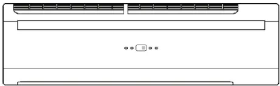
Line drawing of a front panel with ventilation grilles and a control panel (no text or symbols)Cod. 3QE37183 - Rev. 00 - 05/2021
CE
natural_image
Diagram showing a monitor connected to three air conditioner units (no text or symbols visible)max 32 unità
COMANDI DISPONIBILI
natural_image
Isometric line drawing of a rectangular box with internal bands and a handle, labeled Fig. 1 (no text or symbols on the diagram itself)natural_image
Technical line drawing of a mechanical component with labeled part '1' (no text or symbols beyond label)INSTALLAZIONE
natural_image
Technical diagram of a mechanical component with hatched areas and an arrow indicating direction (no text or symbols)Fig. 6

Fig. 7
natural_image
Simple line drawing of a mechanical component with two rods and a central hub, no text or symbols present.INSTALLAZIONE
natural_image
Two circles with arrows pointing downward from each other, intersected by a horizontal line (no text or symbols)NO
SFIATO ARIA
natural_image
Close-up of hands installing or adjusting a copper circuit board with visible wiring and components (no text or symbols)SCARICO CONDENSA
natural_image
Pure technical line drawing of a mechanical joint or bracket (no text or symbols)Fig. 4

natural_image
Pure technical diagram showing intersecting lines and mechanical components without any text or symbolsINSTALLAZIONE
natural_image
Technical line drawing of a rectangular electronic device with internal components and mounting base (no text or symbols)On the indoor PCB are located two DIP switch sets DIPA-S1 (8 Dip) and DIPB-S2 (6 Dip) and two jumper S3 and S4 By a combination of DIP and jumper it's possible set the units in accordance with below description.
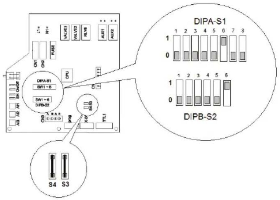
The DIP swith sets DIPA-S1 permit to:
DIP 1 - DIP 6 : set the Master-Slave function
DIP 7, DIP 8: set the product type
The DIP swith sets DIPB-S2 permit to:
DIP 1 : set the meaning of Digital Input ON/OFF
DIP 2 : set 2 or 4 pipe application
DIP 3 : set the presence of valve
DIP 4 : set the temperature control level
DIP 5, DIP 6: set the fan speed
By the two jumper S3 and S4 it's possible:
S3: set the model size
S4: not used
bar
DIPA-S1 | Sample | Value | |---|---| | 1 | 0 | | 2 | 0 | | 3 | 0 | | 4 | 0 | | 5 | 0 | | 6 | 1 | | 7 | 0 | | 8 | 0 |
bar
DIPB-S2 | Sample | Value | |---|---| | 1 | 1 | | 2 | 2 | | 3 | 3 | | 4 | 4 | | 5 | 5 | | 6 | 6 |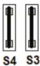
INSTALLAZIONE
Serie DIPB-S2
natural_image
Technical line drawing of a server rack unit with ventilation slots and fan base (no text or symbols)INSTALLAZIONE
Collegamento MASTER-SLAVE
flowchart
graph LR
    A["Air Condition"] --> B["Add Air Condition"]
    B --> C["Back Panel"]
    C --> D["After 20: Temperature Reading"]
- Read the warnings in this instruction booklet carefully since they provide important information on safe installation, use and maintenance.
- This instruction booklet is an integral and essential part of the product and must be kept with care by the user for future reference.
- If the unit is sold or transferred to another owner or if it is to be moved, always make sure the booklet stays with the boiler so that it can be consulted by the new owner and/or installer.
- Installation and maintenance must be carried out by professionally qualified personnel, according to current regulations and the manufacturer's instructions.
- Incorrect installation or inadequate maintenance can result in damage or injury. The manufacturer declines any liability for damage caused by errors in installation and use or by failure to follow the instructions provided.
- Before carrying out any cleaning or maintenance operation, disconnect the unit from the power supply using the system switch and/or the special cut-off devices.
- In case of a fault and/or poor operation, deactivate the unit and do not try to repair it or directly intervene. Contact professionally qualified personnel. Any repair/replacement of the products must only be carried out by qualified personnel using genuine parts. Failure to comply with the above can compromise the safety of the unit.
• Periodic maintenance performed by qualified personnel
is essential in order to ensure proper operation of the unit.
- This unit must only be used for its intended purpose. Any other use is deemed improper and therefore hazardous.
- After unpacking, check the good condition of the contents. The packing materials are potentially hazardous and must not be left within the reach of children.
- The unit can be used by children aged at least 8 years and by persons with reduced physical, sensory or mental capabilities, or lacking experience or the necessary knowledge, only if under supervision or they have received instructions on its safe use and the related risks. Children must not play with the unit. Cleaning and maintenance intended to be done by the user can be carried out by children aged at least 8 years only if under supervision.
- In case of doubt, do not use the unit. Contact the supplier.
- The unit and its accessories must be appropriately disposed of in compliance with current regulations.
- The images given in this manual are a simplified representation of the product. In this representation there may be slight and insignificant differences with respect to the product supplied.

This symbol, which is used on the product, packaging or documents, means that at the end of its useful life, this product must Mnot be collected, recycled or disposed of together with domestic waste.
Improper management of electric or electronic waste can lead to the leakage of hazardous substances contained in the product. For the purpose of preventing damage to health or the environment, users are kindly asked to separate this equipment from other types of waste and to ask for it to be dealt with by the municipal waste service or dealer under the conditions and according to the methods set down in national and international laws transposing the Directive 2012/19/EU.
Separate waste collection and recycling of unused equipment helps to save natural resources and to guarantee that this waste is processed in a manner that is safe for health and the environment. For more information about how to collect electric and electronic equipment and appliances, please contact your local Council or Public Authority competent to issue the relevant permits.

The CE marking certifies that the products meet the essential requirements of the relevant directives in force.
The declaration of conformity may be requested from the manufacturer.
The manufacturer declines all responsibility for any inaccuracies in this manual due to printing or typing errors.
SUMMARY
MAIN FEATURES 4
RECEIPT 4
FOREWORD 4
UNIT DESCRIPTION 4
UNIT TECHNICAL DATA 5
OVERALL DIMENSIONS....6
SAFETY RULES 6
PACKING AND STORAGE 7
UNIT OPENING 7
INSTALLATION 8
UNIT INSTALLATION....8
WATER CONNECTION 9
WALL UNIT INSTALLATIONS 10
AIR VENT....10
CONDENSATE DRAIN 10
UNIT ELECTRICAL CONNECTION.... 11
WIRING DIAGRAM 12
UNIT CONFIGURATION 13
WALL CONTROL INSTALLATION 15
UNIT CLOSING 18
MAIN FEATURES
RECEIPT
On receiving the unit it is essential to check the presence of all the material indicated on the accompanying document, and also that it has not been damaged during transport. If so, immediately inform the forwarder regarding the damage, at the same time also notifying our Customer Care department. Only in this way is it possible to promptly obtain the missing material or compensation for damage.
FOREWORD
The air conditioner is designed and constructed exclusively for air conditioning and must only be used for that purpose. The machine can operate properly and profitably only if used correctly and kept fully efficient. Therefore, please read this instruction handbook carefully and reread it whenever any difficulties or doubts arise. In case of need, our support service, organised in cooperation with our dealers, is always available for any advice and direct assistance.
UNIT DESCRIPTION
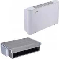
The wall type fan coil unit is a terminal for the treatment of room air in the summer season (coil supplied with cold water) and in winter (coil supplied with hot water).
These units are suitable for indoor installation, very compact and amply configurable to meet the requirements of highly qualified designers.
The careful design of the main components, refined styling and the versatility of the product make it suitable for any type of installation in the residential, commercial or industrial context.
Available in 4 constructional sizes with 1 to 3,71 kW refrigerating power rating and 1,2 to 4,06 kW heating capacity, they are suitable for installation on walls, while their small size provides them with a pleasant appearance.
The cabinet is made of ABS material and provides high mechanical characteristics and resistance to ageing.
It also acts as the bearing structure of the unit.
The ventilating unit consists of a cross-flow fan with an DC brushless motor with very low power consumption
A display on the front panel show the operating status of the units and the setting temperature.
The units are equipped with a pair of flexible hydraulic pipes to facilitate connections to the system. All the units are equipped with a three-way on-off valve. The valve is installed inside the unit and can be easily accessed via the front panel: use of the three-way valve prevents the unit from cooling too much when the fan is at a standstill and also prevents the unpleasant formation of condensation on the casing of the machine.
The units can be connect in Master-Slave mode.
EC motor

3-way valve

Master-Slave system

natural_image
Exterior view of a modern office building (no signage)max 32 unit
CONTROLS
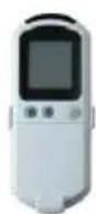
Infrared remote control Rem-I (supplied as standard with the unit)
It set all the function of the units via infrared. It's complete with LCD display, for quick setting of parameters necessary for correct use of the unit.
It's also provided of a wall fixing holder. It permit to control the units from max 7 m distance.
Wire wall control Rem-I (optional)
It set all the function of the units via infrared and it can locally measure the ambient temperature. If used in a Master Slave system it can control singularly any units of the system. It can be use as infer-red receiver. It's equipped with a 7m connecting wire.

MAIN FEATURES
UNIT TECHNICAL DATA
| MODEL UM 15 25 35 45 | |||||||
| Common data | Power supply V-F-Hz 230-1-50 | ||||||
| Air flow rate | max. m^3/h 370 | 500 645 788 | |||||
| med. m^3/h 290 | 370 500 740 | ||||||
| min. m^3/h 220 | 290 370 570 | ||||||
| N° fans N° 1 1 1 1 | |||||||
| Power input (E) | max. W 13 18 | 22 30 | |||||
| med. W 10 13 | 15 20 | ||||||
| min. W | 5 | 10 10 13 | |||||
| Assorbimento motore | max. | A | 0,11 | 0,16 | 0,19 | 0,26 | |
| Coil water content | I | 0,045 | 0,0789 | 0,124 | 0,192 | ||
| Sound power (E) | max. | dB(A) 42 | 45 54 58 | ||||
| med. | dB(A) 38 | 35 43 53 | |||||
| min. dB(A) 33 | 33 40 46 | ||||||
| Sound pressure (1) | max. dB(A) 34 | 39 45 49 | |||||
| med. | dB(A) 29 | 31 34 44 | |||||
| min. dB(A) 24 | 26 31 37 | ||||||
| Hydraulic connection | F | " | 1/2" F | 1/2" F | 1/2" F | 1/2" F | |
| Condensate drain connection | mm 16 | 16 16 16 | |||||
| Valve | Type | 3 way ON-OFF | |||||
| Connection | " | 1/2" | 1/2" | 1/2" | 1/2" | ||
| Heating | Heating capacity (2)(E) | max. kW 1,2 | 2,23 | 3,25 | 4,06 | ||
| med. | kW | 1 | 1,76 | 2,65 | 3,86 | ||
| min. | kW | 0,82 | 1,38 | 2,07 | 3,12 | ||
| Water flow rate (2) | max. | l/h 205 | 380 | 52 690 | |||
| med. | l/h 170 | 301 | 456 656 | ||||
| min. | l/h 140 | 235 | 352 532 | ||||
| Water pressure drop on water side (2)(E) | max. | kPa 18 | 29 39 52 | ||||
| med. | kPa 14 | 19 28 46 | |||||
| min. | kPa | 9 | 12 17 32 | ||||
| Cooling | Total cooling capacity (3)(E) | max. | kW | 1 | 1,82 | 3,01 | 3,71 |
| med. | kW | 0,84 | 1,43 | 2,47 | 3,26 | ||
| min. | kW | 0,68 | 1,21 | 1,86 | 2,66 | ||
| Sensible cooling capacity (3)(E) | max. | kW | 0,85 | 1,53 | 2,22 | 2,74 | |
| med. | kW | 0,71 1,2 | 1,81 2,4 | ||||
| min. | kW | 0,57 | 1 | 1,35 | 1,94 | ||
| Water flow rate (3) | max. | l/h 172 | 313 | 518 638 | |||
| med. | l/h 144 | 246 | 425 561 | ||||
| min. | l/h 117 | 208 320 458 | |||||
| Water pressure drop on water side (3)(E) | max. | kPa 23 | 29 38 50 | ||||
| med. kPa 17 | 19 28 40 | ||||||
| min. | kPa 12 | 12 16 28 | |||||
NOTE:
(1) Sound pressure level in 100m^2 room with 0.5sec of reverberation time
(2) Air T=20°C D.B., water IN/OUT 45°/40°C, Dt water 5°C.
(3) Air T=27°C D.B. / 19°C W.B., Water IN/OUT 7°/12°C, Dt water 5°C.
(E) EUROVENT certified data
INSTALLATION
OVERALL DIMENSIONS
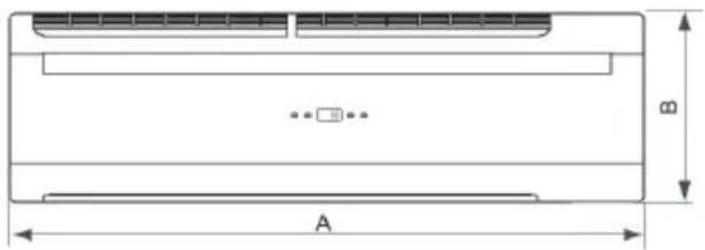

| MOD. | 1525354 | 45UM | |||
| A876mm | |||||
| B300mm | |||||
| C228mm | |||||
| Weigh | 11 | 12 | 13 | 14 | kg |
SAFETY RULES
The following safety rules must be followed carefully in order to prevent injury to the operator and damage to the machine.
• Machine installation must be carried out according to the applicable national regulations
- This installer manual, the user manual and the wiring diagrams are an integral part of the machine. They must be kept together with care and be available to operators for reference whenever necessary.
- Failure to comply with the instructions in this manual and inadequate installation of the air conditioner can void the warranty. The Manufacturer declines any liability for direct and/or indirect damage due to incorrect installation.
• Extraordinary maintenance must be carried out by specialised and qualified personnel.
- During installation, work in a clean and uncluttered place.
- Never touch the moving parts or place anything between them.
- Before turning the air conditioner on, check the integrity and safety of the various components and the entire system.
- Carefully carry out routine maintenance.
- If replacing parts, always ask for original spare parts. Otherwise, the warranty is void.
- Do not remove or tamper with the safety devices.
- Disconnect the power before carrying out any work on the machine.
- Do not place anything on top of the units.
- Do not drop or put anything in the fan protection grilles.
- The surface of the coil is sharp. Do not touch it without protection.
- Carefully read the labels on the machine, never cover them; replace them if damaged.
- Do not use the machine in an explosive atmosphere.
- The power supply line must be equipped with an approved earth.
- If the power cable is damaged, have it replaced by an authorised technician.
- The storage temperature must be between -25^ and 55^ .
- In case of fire, use a powder extinguisher. Do not use water.
- In case of machine faults, make sure they are not due to a lack of routine maintenance. Otherwise, request the assistance of a specialised technician.
• Extraordinary maintenance must be carried out by specialised and qualified personnel.
- Due to the presence of materials subject to regulations and which must be recycled or disposed of at special centres, the machine must not be discarded during scrapping.
- Do not wash the machine with jets of water, steam or corrosive substances.
The Manufacturer, with its assistance network, is in any case available to ensure prompt and careful technical support and all that may be useful for best operation and to obtain maximum efficiency.
INSTALLATION
PACKING AND STORAGE
All models are provided with special cardboard packing specific for each unit. The units must be handled manually. All the information necessary for proper handling during storage and installation is given on the packing. The storage temperature must be between -25^ and 55^ .
N.B.: Do not disperse the packing in the environment.
After deciding on the place of installation (see the relevant sections below), to unpack the two units proceed as follows:
Internal unit (Fig. 1):
- Cut the two nylon straps.
- Open the top part of the packing.
- Grip the unit and lift it completely out of the packing.
- Remove the side protectors and the nylon enclosure.

natural_image
Isometric line drawing of a rectangular box with internal bands and a handle, labeled Fig. 1 (no text or symbols on the diagram itself)UNIT OPENING
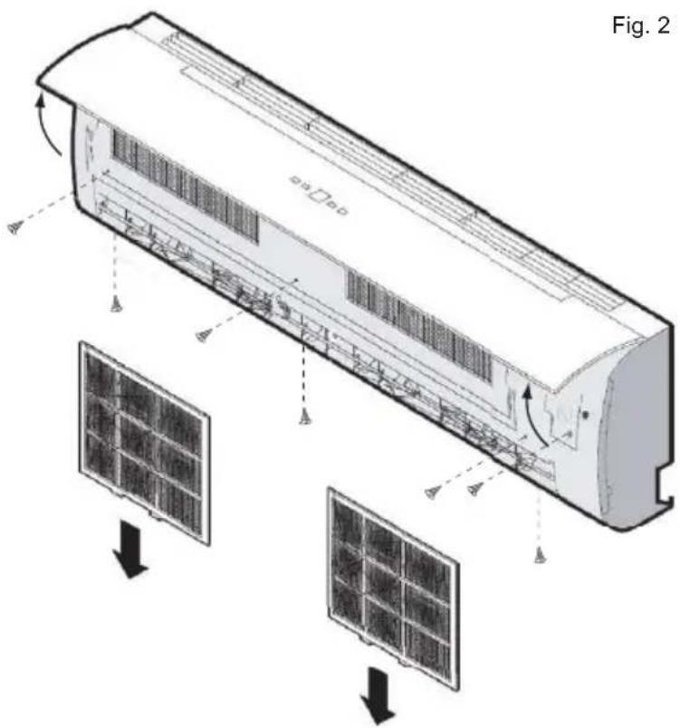
- Lift the cover of the unit
- Disconnect the display connector
- Remove the filters
- Remove the panel
- Carry out the various installation steps
INSTALLATION
UNIT INSTALLATION
Place of installation. Complying with the conditions indicated opposite (Fig. 1), position the unit as low as possible, in any case ensuring 15cm of free space above it. Before carrying out wall mounting, make sure the wall can take the weight of the unit, the air flow is not obstructed by curtains, etc., and that the position is suitable to ensure optimum diffusion of air in the room.
Packing
- Cut the two nylon straps.
- Open the top part of the packing.
- Grip the unit and lift it completely out of the packing.
- Remove the side protectors and the nylon enclosure.
Installation. After choosing where to place the internal unit, use the fixing plate as a template to locate the exact position for the expansion plugs and for the hole through the wall.

Fig. 1
Fig. 2

Fig. 3
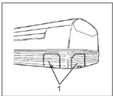
The unit's plastic enclosure has knockouts (1. Fig.3) which, if necessary, can be removed for the hydraulic lines and cables.
natural_image
Technical line drawing of a mechanical component with labeled part '1' (no text or symbols beyond label)INSTALLATION
Proceed as follows:
-
Place the plate on the wall at the appropriate height and fix, keeping it as horizontal as possible (use a level).
-
Mark the position of the fixing holes.
-
Using a drill and a ∅8 mm bit, make the holes for fixing and insert the expansion plugs.
-
Choose the outlet side of the connection pipes. It is advisable to use the rear right outlet. If there are different requirements, refer to the section "OTHER INSTALLATIONS".
-
Make a ∅70 mm hole in the wall (Fig.4), sloping slightly downwards towards the outside, starting from one side of the wall (A) and ending from the opposite side (B) to prevent breakage of the wall itself.
-
fix the plate, with respective screws, to the four previously made holes.
-
Carefully lift and turn the pipe sections required for the connection to the external unit and pass them through the hole.
-
Pass the condensate drain pipe through the same hole. According to requirements, this pipe can also be run in other directions, provided that a minimum slope is always respected to allow the normal flow of condensate.
-
Fit the internal unit securely on the hooks of the fixing plate.
-
Check fixing by moving the unit to the right and left.
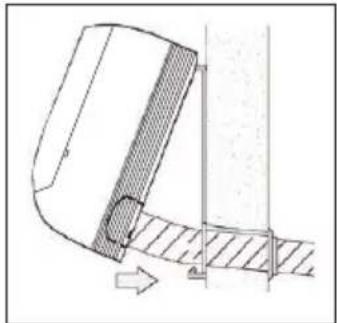
N.B.: To facilitate fixing the unit to the plate, hold the bottom of the unit and lower it upright, guiding the sheath (Fig.5).
In any case, the installer must complete all the operations according to the specific needs.
Other installations.
The unit can also be installed in the following positions;
1 Fig.6. With side outlet
2 Fig.6. With downward outlet
3 Fig.6. With rear outlet
4 Fig.6. With left side outlet (recommended)
WATER CONNECTION
The unit is provided with 1/2" F thread hydraulic connections with flat seal. Make sure to use gaskets to ensure tightness.
CONNECTIONS
The choice and size of the hydraulic lines is left to the designer, who must operate according to the rules of good workmanship and the current regulations.
- position the hydraulic lines
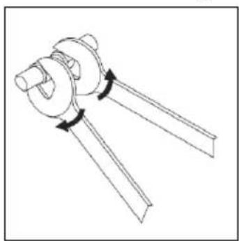
- tighten the connections using the "wrench against wrench" method (Fig.7)
- check for any leakage
- cover the connections with insulating material
The hydraulic lines and connections must be thermally insulated. Avoid partial insulation of pipes. Overtightening can damage the insulation.
Fig. 4

Fig. 5
natural_image
Technical diagram of a mechanical component with hatched areas and an arrow indicating direction (no text or symbols)Fig. 6
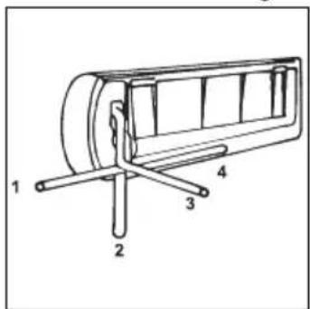
Fig. 7

natural_image
Simple line drawing of a mechanical component with two rods and a central hub, no text or symbols present.INSTALLATION
WALL UNIT INSTALLATIONS
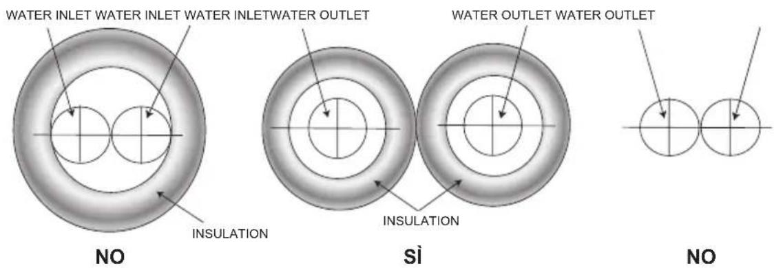
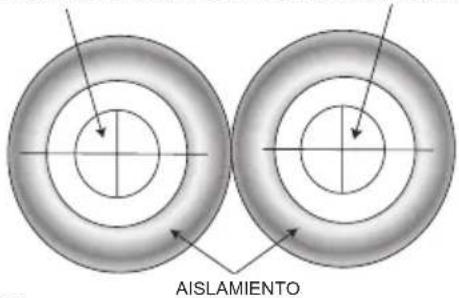
- The insulation must cover both water inlet and outlet pipes as shown
- Use polyethylene insulation (minimum thickness 8mm).
Fig. 1
AIR VENT
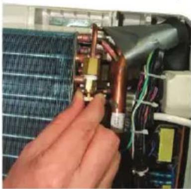
- Connect the water inlet and outlet pipes, turn the unit on and set it to cool mode; make sure the valve opens.
In this way water starts entering the coil. - Check for water leaks along the hydraulic connections.
If there are no leaks, open the air vent and air starts coming out of the coil.
Attention: During these operations, be careful not to touch live electrical parts. - Close the air vent.
CONDENSATE DRAIN
Carry out the condensate drain pipe connection, making sure nothing can hinder the natural drainage of the condensate which forms in cooling mode. Proceed as follows:
Ensure a minimum slope for the flow of condensate
Avoid any hindrances to the flow
After connecting, make sure the water flows properly out of the machine.
- Connect the condensate drain pipe.
- Make sure the drain pipe does not have traps or curves that hinder the flow of condensate.
- Check correct flow by pouring water into the tray and make sure it comes out through the drain pipe installed.
Fig. 2
natural_image
Close-up of hands installing or adjusting a copper-colored electrical component on an air conditioning panel (no visible text or symbols)Fig. 3

natural_image
Pure technical line drawing of a mechanical joint or bracket (no text or symbols)Fig. 4

natural_image
Pure technical diagram showing intersecting lines and a mechanical component (no text or symbols)INSTALLATION
UNIT ELECTRICAL CONNECTION
IMPORTANT:
- The unit must be installed in accordance with the applicable national regulations.
- All the connection cables for the unit, including accessories, must be type H05 VV-F, with PVC insulation in compliance with EN 6033-2-40.
- Disconnect the power to all circuits before accessing live parts.
- Do the earth connection before the electrical connections. In compliance with the installation regulations, the power supply disconnecting devices must ensure a contact opening gap (4 mm) allowing complete disconnection in category III overvoltage conditions.
All the units are equipped with a protection fuse (type gF1A)
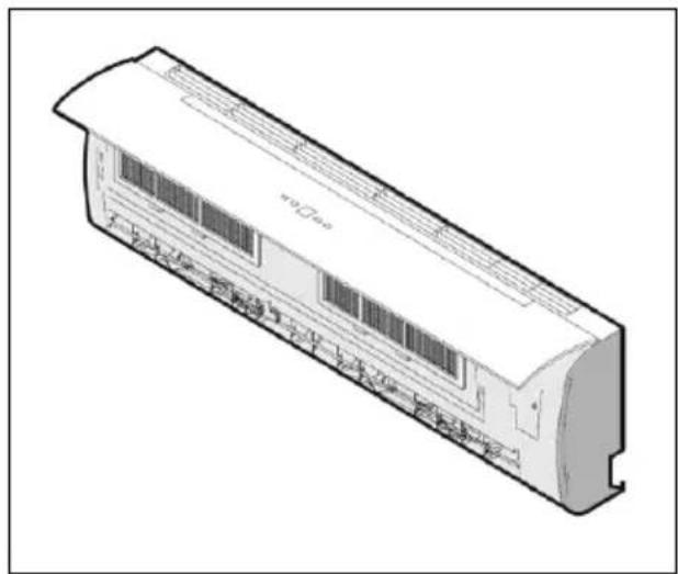
The terminal block is accessible by opening the front panel
Fig. 1
natural_image
Technical line drawing of a rectangular electronic device with internal components and mounting base (no text or symbols)Electrical connection.
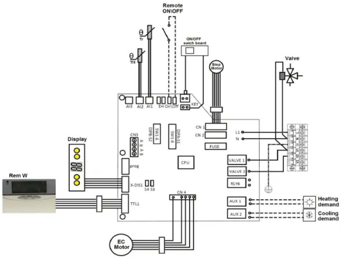
Connect the power supply L (line), N (neutral) and (earth) to the terminal block as shown in the diagram of fig.2, respecting the polarities indicated on the bottom of the electrical boxes
Control board
Fig. 2

Make sure to secure the power cable with the cable clamp located near the terminal block.
INSTALLATION
WIRING DIAGRAM
flowchart
graph TD
    A["Rem W"] --> B["Display"]
    B --> C["CN3 A B A B"]
    C --> D["X-DIS1 S4 S3"]
    D --> E["TTL1"]
    E --> F["EC Motor"]
    F --> G["CN 4"]
    G --> H["CPU"]
    H --> I["FUSE"]
    I --> J["Step Motor"]
    J --> K["ON/OFF switch board"]
    K --> L["Remote ON/OFF"]
    L --> M["Tr"]
    M --> N["AI3 AI2 AI1 EH On/Off KEY"]
    N --> O["Switch Board"]
    O --> P["Valve"]
    P --> Q["L1 N"]
    Q --> R["Valve 1 VALVE 2 RLY6"]
    R --> S["AUX 1 AUX 2"]
    S --> T["Heating demand"]
    S --> U["Cooling demand"]
Symbols
| SIGLA | Funzione | Note | Tipo Segnale | Limiti |
| AUX 1 | It is activated when the unit asks to run heating mode | N.O. voltage free \ | ||
| AUX 2 | It is activated when the unit asks to run cooling mode | N.O. voltage free \ | ||
| Valve 1 | Feeds the valve when the unit asks to run hot or cold | Output 230 Vac | 230 V – 5A | |
| Valve 2 | Feeds the valve when the unit asks to run hot (for setting 4 tube) | not activated | Output 230 Vac | 230 V – 5A |
| RLY6 | Feeds an electrical resistance heating integration with water | not activated | Output 230 Vac | 230 V – 55A |
| AI1 | Tr air probe | \ | Input (NTC 10KΩ @ 25°C) | N.A |
| AI2 | TI1 water probe | \ | Input (NTC 10KΩ @ 25°C) | N.A. |
| AI3 | TI2 water probe | not used | \ | \ |
| On/Off | Signal:- Ignition \ shutdown remote- ECO | The meaning is a function of setting Switch SW1 | ||
| EH | \ | \ | \ | \ |
| CN1 | activate the fins motor | \ | \ | \ |
| CN2 | activate the fins motor | not activated | \ | \ |
| CN3 | Terminal board for Master-Slave | \ | Local BUS | \ |
| CN4 | activate the fans motor | \ | \ | \ |
| TTL1 | Link Rem W | \ | \ | \ |
| X-DIS1 | Link al Display\riceved | \ | \ | \ |
| Prog | Setting | \ | \ | \ |
INSTALLATION
UNIT CONFIGURATION
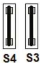
On the indoor PCB are located two DIP swith sets DIPA-S1 (8 Dip) and DIPB-S2 (6 Dip) and two jumper S3 and S4
By a combination of DIP and jumper it's possible set the units in accordance with below description

The DIP swith sets DIPA-S1 permit to:
DIP 1 – DIP 6 : set the Master-Slave function
DIP 7, DIP 8: set the product type
DIPA-S1
The DIP swith sets DIPB-S2 permit to:
DIP 1 : set the meaning of Digital Input ON/OFF
DIP 2 : set 2 or 4 pipe application
DIP 3 : set the presence of valve
DIP 4 : set the temperature control level
DIP 5 , DIP 6 : set the fan speed
DIPB-S2
By the two jumper S3 and S4 it's possible:
S3: set the model size
S4: not used
1
INSTALLATION
DIPB-S2 Seris
| DIP Number | Value Function Status Note | |||
| 1 | 1 Remore ON/OFF | Open | OFF | |
| Close | ON | |||
| 0 ECO Mode | Open | ECO On | ||
| Close | ECO Off | |||
| 2 | 1 4 Pipe Not used | |||
| 0 4 Pipe Default | ||||
| 3 | 1 With valve Default | |||
| 0 Without valve Not used | ||||
| 4 | 1 28°C \ | |||
| 0 36°C Default | ||||
| 5-6 | See Tab.. | Fan speed setting See table 1 | ||
Fan speed table
| Unit size | Fan speed r.p.m | Set | ||||
| Low | Med | High | Jumper S3 | DIP 5 | DIP 6 | |
| 15 | 500 | 600 | 700 | open | 0 | 0 |
| 25 | 600 | 700 | 900 | open | 1 | 0 |
| 35 | 700 | 800 | 1100 | open | 1 | 1 |
| 45 | 900 | 1100 | 1300 | close | 0 | 0 |
DIPA-S1 Series
| DIP Number | Value Function Note | ||
| 1-6 | See tab | Master\Slave setting See table | |
| 7-8 | See tab | System type | See table “System tye” |
Tab. System type
| DIP Number | Function | Note | ||
| 7 | 8 | |||
| Value | 0 | 0 | Cooling and Heating | Default |
| 0 | 1 | Cooling and Heating + Heaters | \ | |
| 1 | 0 | Only Cooling | \ | |
| 1 | 1 | Coling + heating by heaters only | \ | |
INSTALLATION
WALL CONTROL INSTALLATION
First it is necessary to choose where to install the remote control; according to the size and the length of the connections, arrange a raceway suitable for holding the connection cables or a special junction box. The figure below shows the dimensions of the control.
To secure the remote control, remove the front part, carefully remove the electronic board inside (fixed with screws to the rest of the structure) and fix the control by means of two screws, as shown in the figures below.
When installing the remote control, pay special attention to the direction in which it is fixed; make sure the plate is oriented correctly before securing the anchor screws.
Remember the maximum length of the connection cable is 8 m.
Do not install the remote controller in a place where it could come into direct contact with flows of water or large amounts of steam.
Connection with wall control
The wall control must be connected to the unit's control board using the special power cable supplied. The connection must be made to the connector inside the unit's panel:
- disconnect the panel
- connect the cable of the control to the cable on the unit
- close the panel
Fig. 5

natural_image
Technical line drawing of a server rack unit with ventilation grilles and fan array (no text or symbols)INSTALLATION
MASTER-SLAVE connection
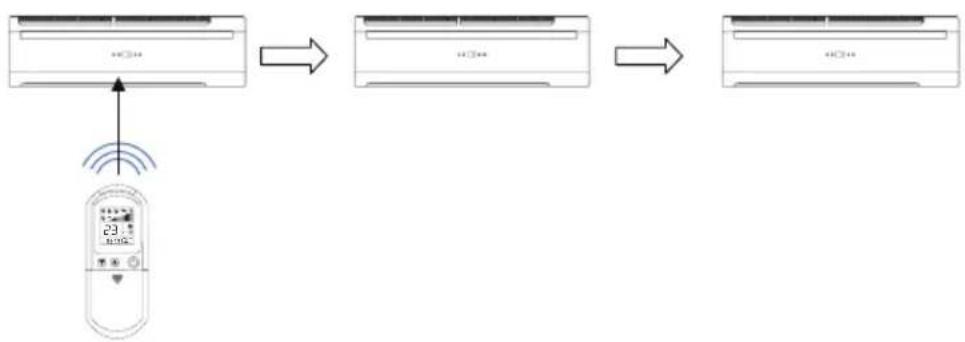
The unit's board allows the sharing with other units of control signals coming from a single control by means of the Master-Slave logic.
The Master unit receives signals from the remote control and sends them to the Slave units which will have the same settings:
-On\Off
-Operation mode
-Fan speed
-Set Point temperature
-Louver setting
-Sleep mode activation
flowchart
graph LR
    A["Air Condition"] --> B["Signal Transmission"]
    B --> C["Digital Controller"]
    C --> D["Final Air Condition"]
For the connection it is necessary to operate on the unit's control board. The connection between different units is done using bipolar cables. Make sure to keep the polarities A and B indicated on the terminal block CN5 (fig.6). Up to 32 units can be connected.


flowchart
graph LR
    A["Signal to next SLAVE"] --> B["CN5"]
    C["Signal from MASTER or from previous SLAVE"] --> B
    B --> D["A"]
    B --> E["B"]
    B --> F["A"]
    B --> G["B"]
INSTALLATION
MASTER-SLAVE configuration
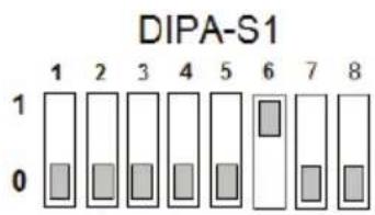
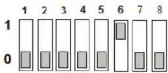
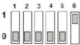
A setting must be made to the units to establish which one is to be assigned the MASTER function and which are the SLAVES. Do not assign two units belonging to the same group as the MASTER function.
Configuration is done through the series of microswitches on the control board indicated by the message DIPA-S1
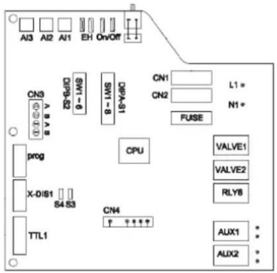
Fig. 7

bar
DIPA-S1 | Sample | Value | |---|---| | 1 | 0 | | 2 | 0 | | 3 | 0 | | 4 | 0 | | 5 | 0 | | 6 | 1 | | 7 | 0 | | 8 | 0 |A different address can also be associated with each Slave unit; this will allow a specific setting to be assigned for each different unit possibly through the MASTER unit. This option is only possible with the use of the wall-mounted control available as an accessory.
For the settings to be made to the first six DIPA-S1 series DIP switches, refer to the table opposite.
| Micro Switch | Indirizzo unità | Note | |||||
| SW1 | SW2 | SW3 | SW4 | SW5 | SW6 | ||
| 0 | 0 | 0 | 0 | 0 | 1 | 1 | Master |
| 0 | 0 | 0 | 0 | 0 | 0 | 1 | Slave |
| 1 | 0 | 0 | 0 | 0 | 0 | 2 | Slave |
| 0 | 1 | 0 | 0 | 0 | 0 | 3 | Slave |
| 1 | 1 | 0 | 0 | 0 | 0 | 4 | Slave |
| 0 | 0 | 1 | 0 | 0 | 0 | 5 | Slave |
| 1 | 0 | 1 | 0 | 0 | 0 | 6 | Slave |
| 0 | 1 | 1 | 0 | 0 | 0 | 7 | Slave |
| 1 | 1 | 1 | 0 | 0 | 0 | 8 | Slave |
| 0 | 0 | 0 | 1 | 0 | 0 | 9 | Slave |
| 1 | 0 | 0 | 1 | 0 | 0 | 10 | Slave |
| 0 | 1 | 0 | 1 | 0 | 0 | 11 | Slave |
| 1 | 1 | 0 | 1 | 0 | 0 | 12 | Slave |
| 0 | 0 | 1 | 1 | 0 | 0 | 13 | Slave |
| 1 | 0 | 1 | 1 | 0 | 0 | 14 | Slave |
| 0 | 1 | 1 | 1 | 0 | 0 | 15 | Slave |
| 1 | 1 | 1 | 1 | 0 | 0 | 16 | Slave |
| 0 | 0 | 0 | 0 | 1 | 0 | 17 | Slave |
| 1 | 0 | 0 | 0 | 1 | 0 | 18 | Slave |
| 0 | 1 | 0 | 0 | 1 | 0 | 19 | Slave |
| 1 | 1 | 0 | 0 | 1 | 0 | 20 | Slave |
| 0 | 0 | 1 | 0 | 1 | 0 | 21 | Slave |
| 1 | 0 | 1 | 0 | 1 | 0 | 22 | Slave |
| 0 | 1 | 1 | 0 | 1 | 0 | 23 | Slave |
| 1 | 1 | 1 | 0 | 1 | 0 | 24 | Slave |
| 0 | 0 | 0 | 1 | 1 | 0 | 25 | Slave |
| 1 | 0 | 0 | 1 | 1 | 0 | 26 | Slave |
| 0 | 1 | 0 | 1 | 1 | 0 | 27 | Slave |
| 1 | 1 | 0 | 1 | 1 | 0 | 28 | Slave |
| 0 | 0 | 1 | 1 | 1 | 0 | 29 | Slave |
| 1 | 0 | 1 | 1 | 1 | 0 | 30 | Slave |
| 0 | 1 | 1 | 1 | 1 | 0 | 31 | Slave |
| 1 | 1 | 1 | 1 | 1 | 0 | 32 | Slave |
INSTALLATION
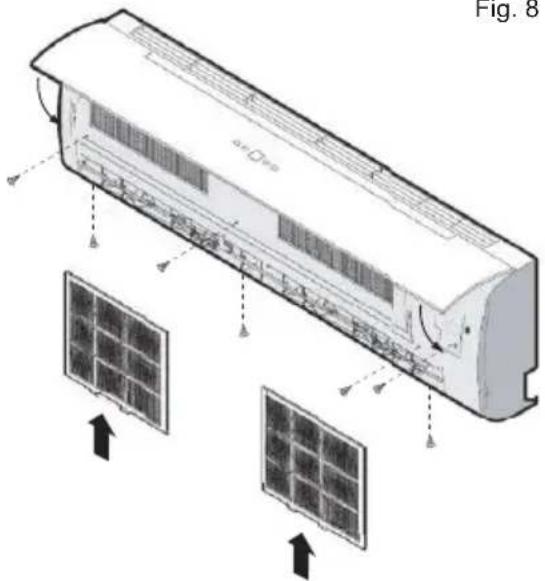
UNIT CLOSING
- Refit the panel
- Insert the filters
- Connect the display connector
- Close the cover of the unit
Fig. 8
natural_image
Diagram showing a monitor connected to three air purifiers (no text or symbols present)hasta 32 unidades
MANDOS DISPONIBLES
natural_image
Isometric line drawing of a rectangular box with internal bands and a handle, labeled 'Fig. 1' (no text or symbols on the diagram itself)APERTURA DE LA UNIDAD
natural_image
Technical line drawing of a mechanical component with labeled part '1' (no text or symbols beyond label)INSTALACIÓN
natural_image
Technical diagram of a mechanical component with hatched areas and an arrow indicating direction (no text or symbols)Fig. 6

Fig. 7

natural_image
Simple line drawing of a mechanical component with two rods and a central hub, no text or symbols present.INSTALACIÓN
NO
si

natural_image
Simple diagram showing two circles with arrows pointing downward, no text or symbols presentNO
PURGADOR DE AIRE
natural_image
Close-up of a hand inserting copper wires into an electrical panel (no visible text or symbols)Fig. 3

natural_image
Pure technical line drawing of a mechanical joint or bracket (no text or symbols)Fig. 4

natural_image
Pure technical diagram showing intersecting lines and mechanical components without any text or symbolsINSTALACIÓN
natural_image
Technical line drawing of a rectangular electronic device with internal components and mounting base (no text or symbols)natural_image
Technical line drawing of a multi-chamber air conditioner unit (no text or symbols)INSTALACIÓN
flowchart
graph TD
    A["Controller with Air Condition"] --> B["Back-to-Back System"]
    B --> C["Monitor with Radio Signal"]
    A --> D["Signal Transmission Signal"]
    D --> E["Display Control"]

- CE
- COMANDI DISPONIBILI
- INSTALLAZIONE
- SFIATO ARIA
- SCARICO CONDENSA
- Collegamento MASTER-SLAVE
- SUMMARY
- MAIN FEATURES 4
- INSTALLATION 8
- MAIN FEATURES
- RECEIPT
- FOREWORD
- UNIT DESCRIPTION
- CONTROLS
- INSTALLATION
- OVERALL DIMENSIONS
- SAFETY RULES
- PACKING AND STORAGE
- Internal unit (Fig. 1):
- UNIT OPENING
- UNIT INSTALLATION
- Packing
- Proceed as follows:
- Other installations.
- WATER CONNECTION
- CONNECTIONS
- WALL UNIT INSTALLATIONS
- AIR VENT
- CONDENSATE DRAIN
- UNIT ELECTRICAL CONNECTION
- IMPORTANT:
- Electrical connection.
- WIRING DIAGRAM
- UNIT CONFIGURATION
- WALL CONTROL INSTALLATION
- Connection with wall control
- MASTER-SLAVE connection
- MASTER-SLAVE configuration
- UNIT CLOSING
- MANDOS DISPONIBLES
- APERTURA DE LA UNIDAD
- INSTALACIÓN
- PURGADOR DE AIRE
Brand : FERROLI
Model : Super Fan
Category : Air conditioner