Jolly Top - Air-conditioner FERROLI - Free user manual and instructions
Find the device manual for free Jolly Top FERROLI in PDF.
User questions about Jolly Top FERROLI
0 question about this device. Answer the ones you know or ask your own.
Ask a new question about this device
Download the instructions for your Air-conditioner in PDF format for free! Find your manual Jolly Top - FERROLI and take your electronic device back in hand. On this page are published all the documents necessary for the use of your device. Jolly Top by FERROLI.
USER MANUAL Jolly Top FERROLI

Cod. 3QE46280 - Rev. 00 - 06/2020
natural_image
White Ferroli air purifier device with ventilation grille (no text or symbols visible on body)I-VM / 3V-VM
natural_image
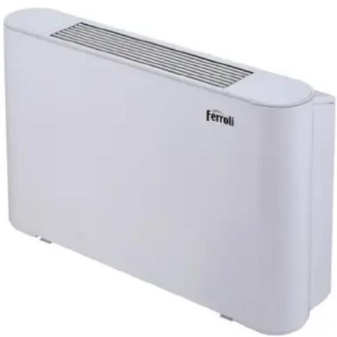
Exterior view of a metallic industrial enclosure or housing unit (no visible text or symbols)I-VN / 3V-VN

CE
IT MANUALE DI INSTALLAZIONE, MANUTENZIONE E USO
EN INSTALLATION, MAINTENANCE AND USER MANUAL
ES MANUAL DE INSTALACIÓN Y FUNCIONAMIENTO
FR MANUEL D'UTILISATION ET D'INSTALLATION
PT MANUAL DE INSTRUÇÕES E DE INSTALAÇÃO
INDICE
1 PANORAMICA PRODOTTO 01
2 AVVERTENZA
text_image
88.5 Controller cablatotext_image
Vite ① Vite ②text_image
Technical diagram of a mechanical housing or enclosure with numbered annotations indicating structural components.text_image
Base ① ① ② Base PiediniFigura 5-3
natural_image
Line drawing of a rectangular device with a mesh grille and vertical supports (no text or symbols)natural_image
Pure technical diagram of a heat exchanger or cooling unit with no text, numbers, or symbols
natural_image
Technical line drawing of a rectangular enclosure with internal compartments (no text or symbols)Figura 5-6 8 QLWj GDQLQFDVVR
text_image
d btext_image
a b d E FFigura 5-10 8 QLMj IGDILQFDVVR
text_image
d a a b Figura 5-7
natural_image
Technical line drawing of a mechanical component with labeled dimensions 'a' (no text or symbols beyond basic lines)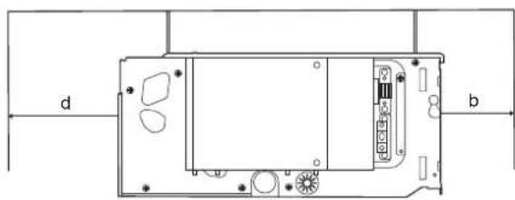
natural_image
Technical diagram of a device rear panel with labeled ports (d and b) and internal components (no text or symbols beyond labels)Figura 5-11 8 QLWj NGDQLQFDVVR
1 PRODUCT OVERVIEW 01
2 WARNING
• 2.1 Meaning of various labels 02
• 2.2 Warning 02
• 2.3 Note 02
• 2.4 Information 03
3 OPERATION INSTRUCTIONS
• 3.1 Standard conditions for use 03
• 3.2 Switch and control 03
• 3.3 Air supply direction adjustment 05
4 CLEANING AND MAINTENANCE
• 4.1 Maintenance by customer 05
• 4.2 Professional maintenance 06
5 INSTALLATION INSTRUCTIONS
- 5.1 Packaging and assembly 08
- 5.2 Handling instructions 08
- 5.3 Installation 08
• 5.4 Liquid pipe connections 11
• 5.5 Electrical connection 13
• 5.6 Startup guide 16
6 SERVICE GUIDE
- 6.1 Troubleshooting 16
- 6.2 Non-unit related faults 17
- 6.3 Product data 18
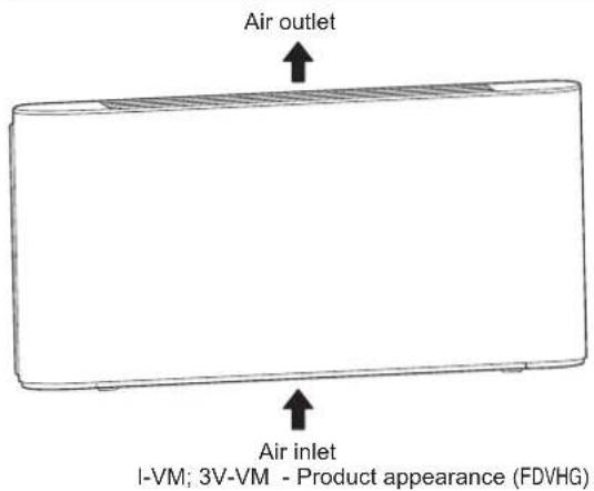
1 PRODUCT OVERVIEW
This ceiling & floor type unit is used for indoor air quality regulation in various scenes. It is intended to be used by expert or trained users in shops, in light industry and on farms, or for commercial use by lay persons.
NOTE
The figures here are for reference only and may have differences with the actual product you received.
text_image
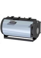
Air outlet Air inlet I-VM; 3V-VM - Product appearance (FDVHG)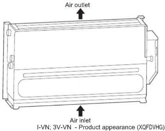
text_image
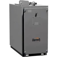
Air outlet Air inlet I-VN; 3V-VN - Product appearance (XQFDVHG)| NO. | Name | Schematic Unit Qty Remarks | |||
| 1 | Operation and Installation Manual |  | Pcs | Accessories | |
| 2 | Fastening screw | Pcs | 4 | To be purchased separately | |
| 3 | Three-way valve and its piping assembly |  | Set | 1 | To be purchased separately from the manufacturer |
| 4 | Footing | 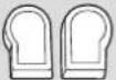 | Set | 1 | To be purchased separately from the manufacturer |
| 5 | Auxiliary drain pan |  | Pcs | 1 | To be purchased separately from the manufacturer |
| 6 | Wired controller |  | 1 | To be purchased separatelyPcs | |
| 7 | Inlet hose | 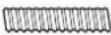 | 1 | To be purchased separatelyPcs | |
| 8 | Outlet hose |  | 1 | To be purchased separatelyPcs | |
| 9 | Filter |  | 1 | To be purchased separatelyPcs | |
| 10 | Check valve (inlet and outlet pipes) |  | 2 | To be purchased separatelyPcs | |
| 11 | Drain pipe |  | 1 | To be purchased separatelyPcs | |
2 WARNING
This section describes important safety information.
Please read the Manual carefully, especially those operating standards with "Warning" or "Note" signs. Failure to abide by these standards may lead to personal injury or damages to the unit or other items.
For any faults not covered by the Manual, please contact the manufacturer immediately.
Tampering with the unit can result in very hazardous situations. The manufacturer does not accept liability for damage resulting from unauthorized or inappropriate changes to the product.
2.1 Meaning of various labels

WARNING
A situation that may lead to death or injury.

NOTE
A situation that may cause damage to the unit or loss of property.

INFORMATION
Indicates a useful hint or additional information.
2.2 Warning
- Ask qualified professional staff to install (install for the first time, change the place of the unit or re-install) and repair the unit and its parts. Do not attempt to install or repair the air conditioner by yourself, as any improper operations may lead to fire, electric shock, personal injury or water leakage.
- Make sure the unit is grounded reliably in accordance with the laws. Otherwise, it may cause electric shock.
- Stop using the air conditioner and consult your dealer in case of any abnormalities. Otherwise, fire or electric shock may occur.
- Do not attempt to maintain or alter the unit by yourself. Improper operations may cause water leakage, electric shock or fire.
- Make sure the leakage protection device is installed, or electric shock may occur.
- Do not wash the unit with water, or electric shock may occur.
- To avoid electric shock, do not place any water-filled container on the unit.
- Do not operate the switch with wet hands, or electric shock may occur.
- Do not put your fingers or other objects into the unit, it can result in serious injury.
- Do not obstruct the air supply channel, as that may result in personal injury or damages to the unit.
- Check that the supporting structure of the unit is securely installed after a long period of use, to prevent fall accidents.
- Make sure the installation base and hoisting are robust and reliable; otherwise, the unit may fall and lead to accidents.
- Do not expose yourself to cold air over a long period. Too low temperature may cause harm to your health.
- Do not expose animals or plants to air outlet to avoid any harm.
-
This unit is intended for air handling only. Do not use it for animal rearing.
-
Do not install the unit where flammable gas may leak. Otherwise, fire may occur. Do not install the unit in potentially explosive atmospheres.
- Keep the unit far away from combustible spray to avoid fire.
- Use proper fuse. Do not use iron wire or copper wire, as it may cause fire or unit abnormality.
- When connecting power supply to the unit, follow the regulations of the local electric company.
- Provide separate power switch to ensure the unit can be disconnected from power properly.
- Do not use this unit to store spare parts or other items.
- Please attach enough importance to the signs and symbols indicated on the unit. Any other potential hazards not covered in the Manual (if any) should be specified in labels attached to the unit.
- For safety concerns, only the manufacturer or its service agent or a similarly qualified person can replace a damaged wire.
2.3 Note
- Read the Manual carefully and perform a safety inspection in advance so that you can be fully aware of the possible dangers as you use or install the unit.
- The manufacturer shall not be liable for any personal or animal injury or damage to any object caused by incorrect installation, adjustment, maintenance or improper use.
- The manufacturer is not held liable for any damages resulting from faulty operations against this Manual.
- Do not expose this unit to wet or humid environments as this may damage the electrical components.
- Do not store this unit in the open air. Do not stack unpackaged units.
- Do not use this unit to store food, plants, precision instruments, artwork, etc.
- To operate the unit for the first time, exhaust the air in the coil; otherwise, the performance may be compromised.
- Clean the inside of the water pipe before use.
- Remember to implement anti-freezing measures for coil in winter. For details, please refer to anti-freezing instructions herein.
- Keep the unit energized even if it is not in service over a long period.
- Adopt self-protection measures when you install, maintain or clean the unit.
- Do not press the unit. Handle it carefully as any damages may cause unit malfunction.
- Reserve enough space for installation and maintenance.
- Before installation, check whether the unit is reliably grounded. Otherwise, do not proceed with the installation. In no circumstances can the earth line for main power switch be disconnected.
-
Rotate the fan impeller during installation. Contact the manufacturer if you hear any abnormal noises.
-
Make sure that the water discharge pipeline can provide smooth drainage. Improper installation of the water discharge pipeline may lead to water leakage, and damages to furniture.
- Make sure the liquid pipeline and air duct are reliably supported. Make sure pipes and connectors are not distorted.
- The water inlet and outlet pipes must have check valves installed and be wrapped with insulation materials.
- Connect the wires as required. Otherwise, it may cause damage to electrical parts.
- The actual power supply must be consistent with the nominal nameplate value, or permanent damage may occur.
• Use power cord with a proper diameter. - Do not use damaged cables. Replace the damaged cables immediately if necessary. Do not attempt to repair the damaged cables.
- Keep for future reference.
2.4 Information
- Keep the unit serial number available for future reference and in case when you need to contact the after-sales service.
- Do not bring any combustible materials near the air outlet.
- Transport the unit as per requirements indicated on the package.
- Avoid crash, fall-over or squeeze and keep away from rain and snow during transportation.
- Store the unit in a clean, dry, fire-proof and well-ventilated place without any corrosive gas.
- To avoid shock during transportation, fix the unit and its accessories on the transportation platform with ropes or by other means.
3 OPERATION INSTRUCTIONS
This appliance can be used by children aged 8 and above and persons with reduced physical, sensory or mental capabilities or lack of experience and knowledge if they have been given supervision or instruction concerning use of the appliance in a safe way and understand the hazards involved.
Cleaning and maintenance shall not be made by children without supervision.
- The manufacturer is not responsible for unit damages or personal injury resulting from unauthorized operations or use of non-original parts or accessories.
- Ventilation
Periodically ventilate the room where the unit is installed. Ventilation is especially important in case the room has many people in it or has flammable devices or gas sources. Poor ventilation may result in lack of oxygen.
- Before unit operation, clean water pipes to prevent them from being blocked.
- Upon FCU test run or switching between hot and cold water, open the vent valve to exhaust air in the coil until water flows out. Otherwise, the heat exchange performance may be significantly compromised.
- During operation
Filter is normally not removed except for maintenance purpose, as doing so may cause foreign objects to enter the unit.
- In normal cases
In cooling mode, fog may appear at the air outlet.
3.1 Standard conditions for use
Use the unit in the following temperature range for safe and effective operation.
| Mode Indoor temperature | |
| Cooling | 17-32°C |
| Heating | 0-30°C |
The unit can achieve optimum performance when running within the temperature range listed above. At a temperature beyond the listed ranges, unit faulty may occur.
The unit can only operate normally as long as you strictly adhere to the regulations outlined in the Manual.
Water inlet temperature range is 3-75°C.
Water inlet temperature range recommended is 3-65°C.
Water inlet pressure range is 0-1.6MPa.
3.2 Switch and control
The wired controller should be purchased separately from the manufacturer. Other wired controllers are not applicable.
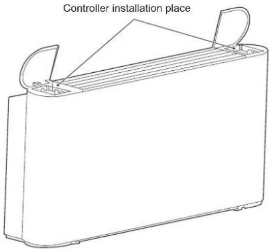
Installation position of wired controller
You can install the wired controller on the left, or right of the unit or on the wall as required. Make sure the wired controller is close to the electric control box.
Please refer to the Wired Controller Operation and Installation Manual for installation methods.
text_image
Controller installation placeFigure 3-1 Installation position of wired controller
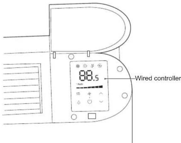
text_image
88.5 Wired controllerFigure 3-2 After installation of wired controller (only for I-VM units)
The Operation Manual is provided with the wired controller.
You can complete the following operations using the manufacturer's wired controller:
Start/stop the unit.
Switch between seven fan speeds and auto.
Constant temperature set within a desired range.
Switch among Cool, Heat, Dry, and Auto.
0-10V wired controller output DC voltage signal to main board. The main board receives the signal and controls the motor according to the corresponding speed.
Table 3-1 ☐90 ☐0-10V wired controller output signal specification
| Controller output voltage | Fan speed | |
| Seven fan speeds | 0 ≤ Voltage<1 | Shutdown |
| 1 ≤ Voltage<3 | Low | |
| 3 ≤ Voltage<4 | Medium low | |
| 4 ≤ Voltage<5 | Medium | |
| 5 ≤ Voltage<6 | Medium high | |
| 6 ≤ Voltage<7 | High | |
| 7 ≤ Voltage<8 | Super high | |
| 8 ≤ Voltage<10 | Strong | |
| Auto speed | The wired controller is adjusted according to the logic of the seven-level control system. | |
1) Start and stop
Start or stop the unit using the wired controller or centralized controller.
| 1 | Start the unit after it has not been used for a long time | Before starting the unit again, you should:Clean or replace the air filter.Clean the heat exchanger.Make sure the drain pipe for drain pan of heat exchanger is clean; if not, wash it.Remove air from the water system. |
| 2 | Leave the unit unused for a long period | If the unit is not to be used in winter, drain the water system when appropriate. Otherwise, the water in the system may freeze, thus causing damage to the unit, or leading to water leakage, electric shock or damage to furniture. |
3.3 Air supply direction adjustment
You can manually adjust the louver to change the air supply direction.
NOTE
Do not touch the heat exchanger to avoid any personal injury.
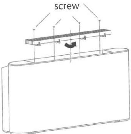
To adjust the air supply direction, do as follows:
1) Remove the screws (M3.9*10) fixing the louver.
2) Disassemble the louver manually.
3) Rotate the louver by 180^ and then put it back manually.
4) Put the screws back and fasten them.
text_image
screwFigure 3-3 Adjusting the air supply direction
4 CLEANING AND MAINTENANCE
4.1 Maintenance by customer
NOTE
Cleaning and maintenance must not be performed by minors without supervision.
Cleaning the outer surface of the unit is permitted. Dip a piece of soft cloth in cold water and alcohol to clean the unit. Do not use hot water, solvent, abrasive or corrosive substances.
NOTE
Disconnect the unit from power supply before cleaning or maintenance.
Do not spray water on the unit.
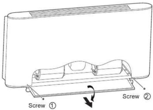
1) Cleaning the air filter
To ensure proper air return, clean the air filter at least once every month. If used in a dusty environment, the filter must be cleaned on a more frequent basis. Take the air filter out before you can clean it.
The filter is at the bottom of the unit, while the air return outlet is at the bottom or the rear side.
To take the air filter out, do as follows:
a) Remove the screws ① and ②.
b) Rotate the filter bracket.
c) Pull out the filter.
text_image
Screw ① Screw ②Figure 4-1 Removing the filter
Blow the air filter with compressed air or clean it in water.
Before putting the filter back, make sure it is clean and dry. If it is damaged, replace it with a new one.
4.2 Professional maintenance
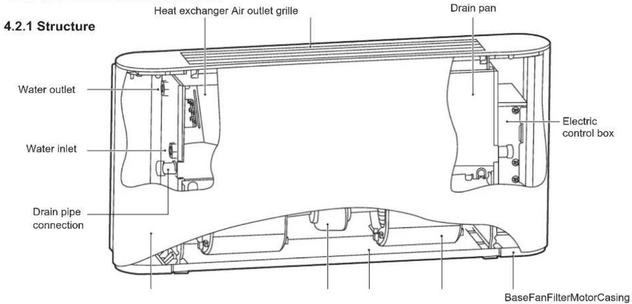
text_image
4.2.1 Structure Heat exchanger Air outlet grille Drain pan Water outlet Water inlet Drain pipe connection Electric control box BaseFanFilterMotorCasingFigure 4-2 Unit cased
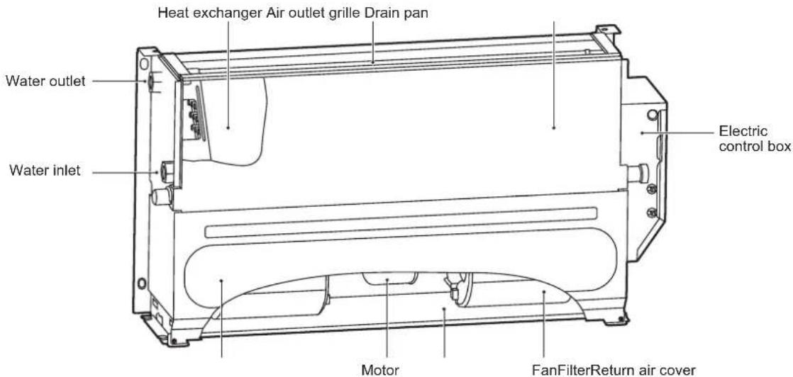
text_image
Heat exchanger Air outlet grille Drain pan Water outlet Water inlet Electric control box Motor FanFilterReturn air coverFigure 4-3 Unit uncased
For dual-pipe system and four-pipe cold water coil, the water inlet and outlet joints are G3/4. For four-pipe hot water coil, the water inlet and outlet joints are G1/2.
The casing of the unit is made of galvanized steel; the air filter is made of nylon fibre, and the aluminum alloy air filter can be customized; the motor has internal overheat protection and overcurrent protection; a centrifugal rotating fan is used; a soundproof material such as sponge is used; the fin type heat exchanger is composed of copper pipe and aluminum foil, and the heat exchanger pipe connection can be changed on site.
4.2.2 Maintenance
NOTE
Only qualified technicians who have unit and refrigeration system experience can perform maintenance operation. Proper gloves are required.
Before maintenance or check, disconnect the unit from power supply, keep the main switch closed with warning sign attached, to prevent others from resuming the power accidentally.
1) Routine maintenance
2) Once every month
Check whether the air filter is clean. The air filter is washable as it is made of fibre. When the unit is operational, make sure you check the air filter every month.
3) Once every six months
Check whether the heat exchanger and condensate drain pipe are clean. After power disconnection, disassemble the unit to check the heat exchanger and condensate drain pipe.
4) If necessary, you should:
a) Remove any foreign matters that may impede air flow.
b) Remove the dust with compressed air or clean water and avoid damage to the heat exchanger.
c) Dry with compressed air.
d) Check for any impurities in the drain pipe that may impede water flow.
e) Check whether the system has air.
- Start and let the system run for several minutes.
- Stop the system.
- Open the air discharge valve to remove air.
- Repeat this operation until the air is exhausted.
5) Maintain the circuits.
Check whether the power cord, electrical contacts, terminals, etc. are loose or damaged.
6) If the motor needs to be replaced, follow the steps below:
a) Unplug the unit.
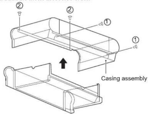
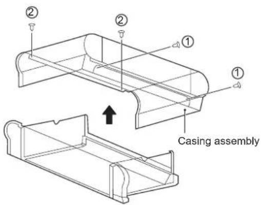
b) As shown in Figure 4-4, remove screws ①*2 and ②*2 and then the casing.
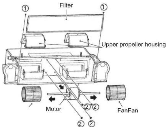
c) As shown in Figure 4-5, remove screws ①*2 to take the filter out.
Then, remove the upper volute.
After that, remove four screws (2) that fix the motor, to disconnect the motor cable and the main board. Then, take out the fan and the motor.
Disassemble the fan to get the motor.
Install back the motor in reverse order.
text_image
② ② ① ① Casing assemblyFigure 4-4 Removal of casing
text_image
Filter Upper propeller housing Motor FanFanFigure 4-5 Removal of filter, upper volute and motor screws
7) If the heat exchanger needs to be replaced, follow the steps below:
a) Unplug the unit.
b) Shut off the water supply.
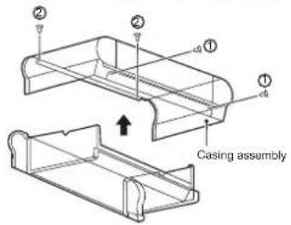
c) As shown in Figure 4-6, remove screws ①*2 and ②*2 and then the casing.
d) Drain the coil.
e) Disassemble the inlet and outlet pipes.
f) As shown in Figure 4-7, remove screws ①*2 to remove the electric control box.
g) As shown in Figure 4-8, remove screws ①*7 to take the drain pan out. Then, remove screws ②*4 to take the heat exchanger out.
h) Pull out the temperature sensor plug.
Install back the heat exchanger in reverse order.
text_image
Casing assembly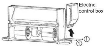
text_image
Electric control box ①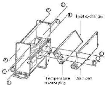
text_image
Heat exchanger Temperature sensor plug Drain panFigure 4-6 Removal of casing Figure 4-7 Removal of the electric peak exchanger
8) If the unit or its parts need(s) to be removed, make sure that:
Only a professional person can disassemble the unit.
The system with antifreeze must not be discarded; otherwise, it will cause pollution. It should be collected and then be disposed off properly.
As a special waste, electronic components must be handled by professional persons together with polyurethane foam, polyurethane and sound absorbing sponge.
5 INSTALLATION INSTRUCTIONS
NOTE
- The instructions are applicable to IDU only.
- Customization is required for use in salty surroundings (close to the shore).
• Install the water softening device if hard water that has a high salt content is to be supplied to the coil. - Handle with care. Do not exert too much pressure on the unit.
- Any damages to the fan, unit surface or piping may cause faults.
5.1 Packaging and assembly
Only trained professionals can move and lift the unit.
Upon arrival of the unit, you must check whether it is intact and provided with complete accessories. Using damaged unit may be hazardous.
1) When removing the unit package, follow the steps below:
Check whether the package and unit are intact and whether accessories are complete.
Unpack the unit.
Dispose off packaging materials at a suitable waste receiving or recycling station, depending on the laws of the country or locality where the installation is to be done.
Place the package out of the reach of children.
5.2 Handling instructions
Wear personal protective equipment during handling.
To avoid damages to external structures, internal mechanical and electrical components, caution must be exercised during handling.
Make sure there are no obstacles or pedestrians along the way in case collisions or crushing occurs or lifting or handling equipment falls over.
All of the following operations must be performed in accordance with current health and safety regulations, including the equipment used and the procedures followed. Before operation, verify that the lifting device is capable of lifting the unit.
You can lift or move the unit using your hand or using a proper handcart. For a unit that weighs over 30 kg, package it before it can be lifted using a crane or by similar means.
5.3 Installation
Follow the instructions when installing the unit.
Read the Manual carefully before proceeding with any operations. Installation can be only performed by a professional technician. Incorrect installation may lead to unit faults or degraded performance.
You must abide by the regulations of the country or locality where the installation is located.
Before installation, unpack the unit and its accessory, and find the attached Operation and Installation Manual and related assembly.
The support surface of installation must be strong enough to bear the weight of the unit.
Before installation, check with the customer whether the wall or ground where installation is located has buried wires, water pipes or gas pipes.
Make sure the inlet and outlet pipes and drain pipe are air-tight.
1) Check the space technically required for installation:
Space required for installation.
Space required for connecting the liquid lines and other valves.
Space required for connecting power supply.
Space required for connecting the unit to the external control panel (if any).
Space required for setting flow route and air inlet (for specific models).
Space required for correct and sufficient air flow.
Space required for removing condensate water.
Space required for cleaning the filter.
Space required for cleaning internal assembly and maintenance.
2) Installation guide:
Remove the casing:
Remove screws ①*2 and ②*2 and then the casing.
text_image
② ② ① ① Casing assemblyFigure 5-1
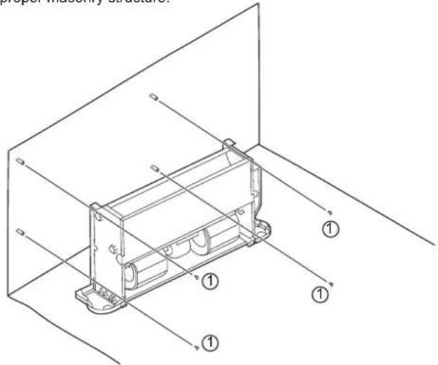
Mark the places for screws on the wall according to the unit mounting holes or dimensions specified in Figure 5-12. The drain pipe for condensate water must be smooth enough to allow unobstructed water discharge.
As shown in Figure 5-2, fasten four screws (①) into a proper masonry structure.
text_image
proper assembly structure. ① ① ① ①Figure 5-2 Diagram for fixing the unit body
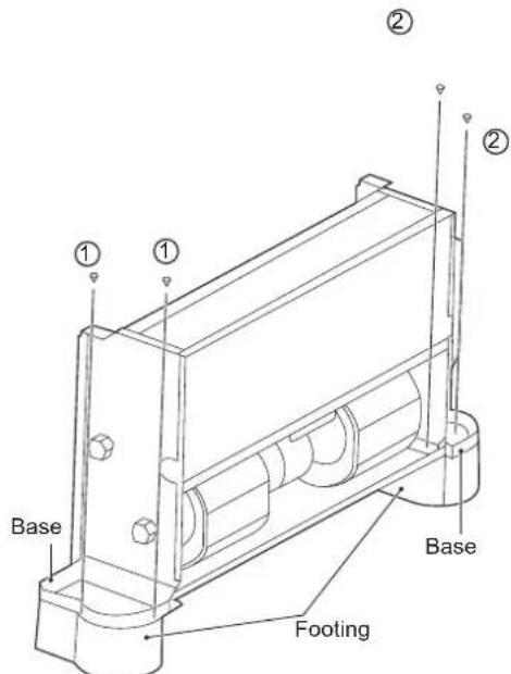
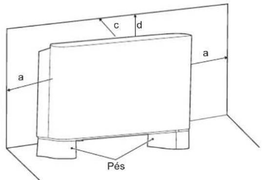
The footings shown in Figure 5-3 are optional. You can purchase them separately and install them as follows:
- Put the footings beside the unit to be installed.
- Place the mounting holes on the unit base into the corresponding footing locating pin and install screws ①*2 and ②*2 to fix the footing according to Figure 5-3.
text_image
Base ① ① ② ② Base FootingFigure 5-3
3) Install the unit following the steps below in case it is ceiling mounted.
To match the existing structure, set the screw pitch according to the unit dimensions.
| Wood structure | Original concrete slab structure |
| Structure the square rod on the beam to set the lifting bolts. | Use embedded bolts, and pull bolts. |
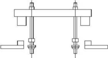 | 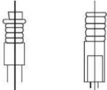 |
Steel frameworkDirectly set and use an angle steel for support.Suspension bolt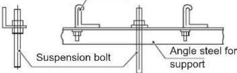 | Newly set concrete slab structureSet using embedded appliances, and embedded type of bolts.Sliding-type insertion piece  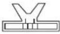 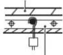 Knife-type insertion piece Embedded bolt(hanging and embedded bolt of piping) Knife-type insertion piece Embedded bolt(hanging and embedded bolt of piping) | |
Figure 5-4 Installation of lifting bolts
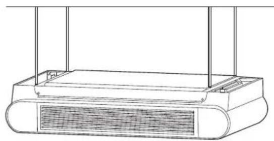
natural_image
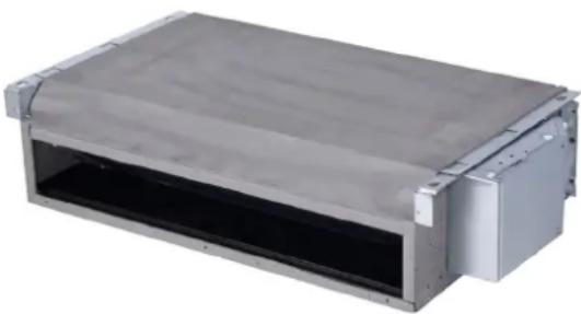
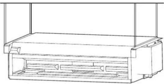
Line drawing of a rectangular device with a mesh grille and vertical supports (no text or symbols)Figure 5-5 Diagram of ceiling FDVHG
text_image
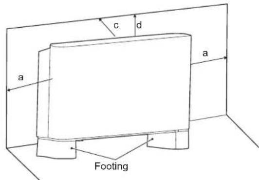
c d a a FootingFigure 5-8
natural_image
Pure technical diagram of a heat exchanger or cooling unit with no text, numbers, or symbols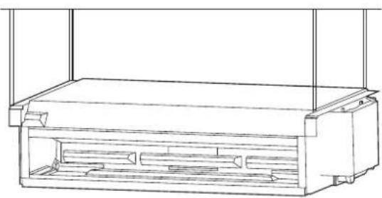
natural_image
Technical line drawing of a rectangular enclosure or storage unit with internal compartments (no text or symbols)Figure 5-6 Diagram of ceiling☐XQFDVHG

text_image
d bFigure 5-9 Ceiling FDVHG

text_image
a b d aFigure 5-10 Vertical type XQFDVHG
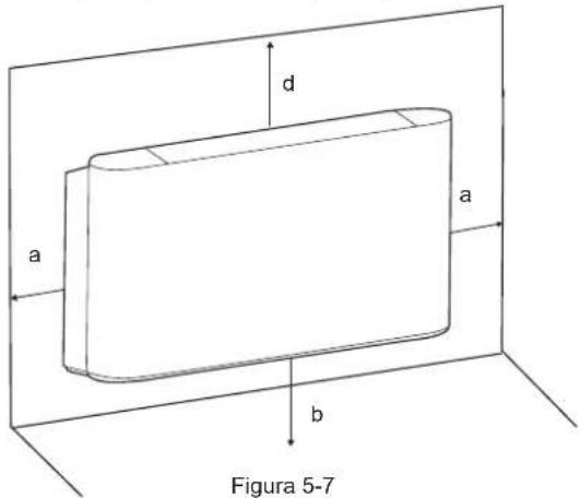
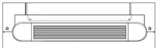
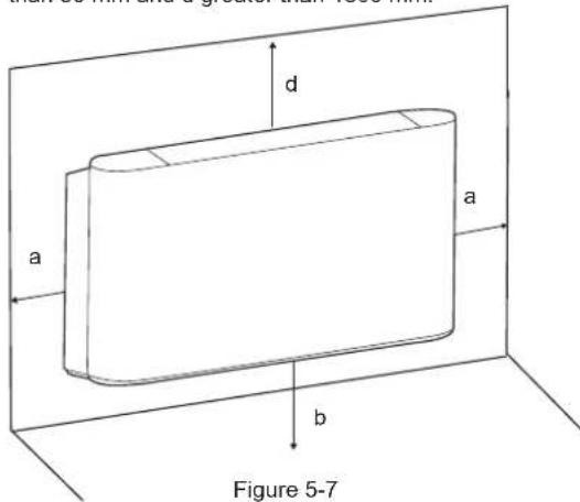
5.3.1 Spacing and positioning
Incorrect positioning or installation may increase the noises and vibration of the unit during operation.
If not enough space is reserved during installation, the unit may face difficult maintenance and reduced performance.
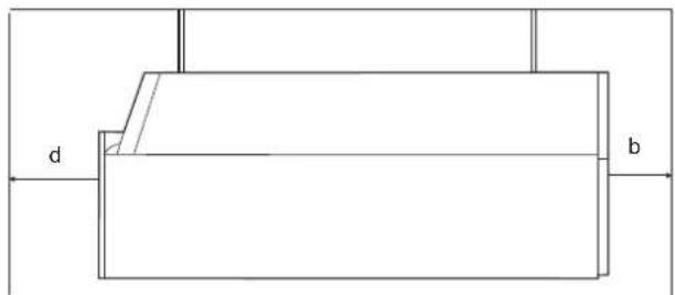
The unit allows vertical installation, provided that correct positioning is arranged in advance. As shown below, a is greater than 150 mm, b greater than 90 mm, c greater than 50 mm and d greater than 1500 mm.
text_image
d a a b Figure 5-7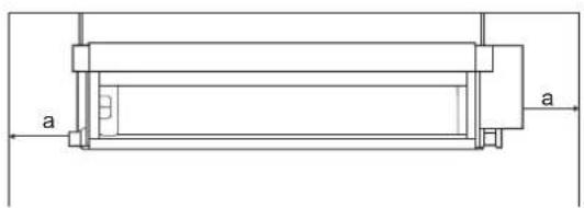
natural_image
Technical line drawing of a mechanical component with labeled dimensions 'a' (no text or symbols beyond basic lines)
natural_image
Technical diagram of a device rear panel with labeled ports (d, b) and internal components (no text or symbols beyond labels)Figure 5-11 Ceiling XQFDVHG
- Do not consider the unit as a surface that can be relied on during actual use. Reserve enough space during installation for ventilation purpose.
• Using water or spray near the unit can cause electric shock and malfunction.
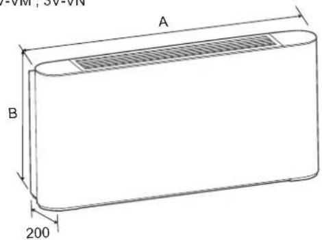
5.3.2 Dimensions
DC= I-VM ; I-VN
AC=3V-VM;3V-VN
Unit: mm
text_image
VM, SV-VN A B 200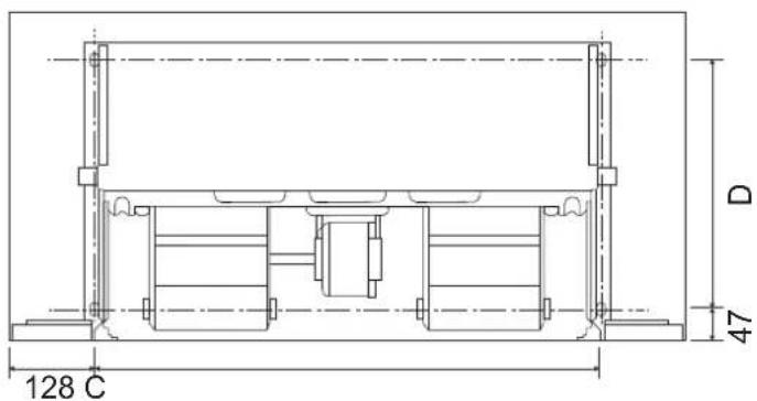
text_image
128 C D 47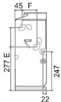
text_image
45 F 277 E 247 22
text_image
G H 200
text_image
C 71(DC) 39(AC)Figure 5-12
Table 5-1 Unit: mm
| Model | 150 250 350 500 700 800 | |||||
| A | 790 | 1020 | 1240 | 1240 | 1360 | 1360 |
| B | 495 | 495 | 495 | 495 | 495 | 591 |
| C | 534 | 764 | 984 | 984 | 1104 | 1104 |
| D | 375 | 375 | 375 | 375 | 375 | 391 |
| E | 123 | 123 | 123 | 123 | 123 | 219 |
| F | 93 | 93 | 93 | 93 | 93 | 102 |
| G | 628 | 858 | 1078 | 1078 | 1198 | 1198 |
| H | 455 | 455 | 455 | 455 | 455 | 551 |
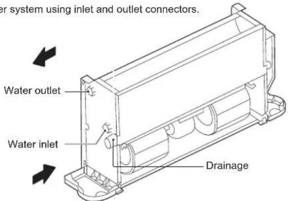
5.4 Liquid pipe connections
1) Only professionals can operate the liquid pipes.
Drain pipe must be the different side with the electric control box.
Connect the unit to the water system using inlet and outlet connectors.
text_image
Water system using inlet and outlet connectors. Water outlet Water inlet DrainageFigure 5-13
All water system coils are equipped with discharge and drain valves.
Use a screwdriver or wrench to open and close the valve.
2) When installation is complete,
a) Remove air inside pipes.
b) Wrap the connecting pipes and all the valve body with anti-condensation material (EPDM or PE) of no less than 10 mm thick or install auxiliary drainage equipment.
c) Pour water into the drain pan and check it all the way until you can see water flows from the drain outlet. Alternatively, you may check the drain channel and remove impurities that may obstruct the flow.
d) Install the condensate drain system.
e) The condensate drain system must be properly lowered to ensure water discharge.
Follow the steps below to set the condensate drain system.
Make sure the drain connector is stress-free
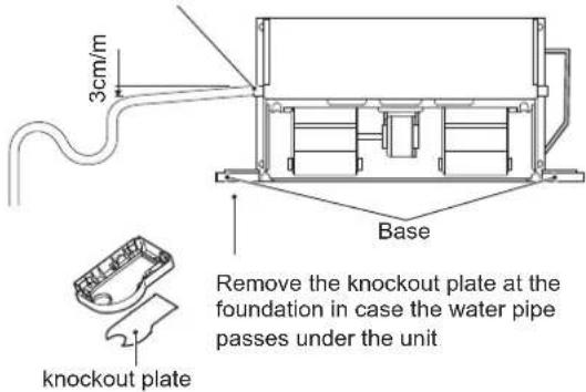
text_image
3cm/m Base Remove the knockout plate at the foundation in case the water pipe passes under the unit knockout plateFigure 5-14
3) Set water storage elbow
The condensate drain system must be fitted with a suitable elbow to prevent odour penetration. Follow the steps below to set the elbow.
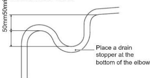
text_image
50mm50mm Place a drain stopper at the bottom of the elbowFigure 5-15
The customer has to purchase the three-way valve and its accessories (Operation and Installation Manual attached) separately from the manufacturer.
The customer may also need to purchase the auxiliary drain pan separately from the manufacturer if required.
See the steps below for installation of auxiliary drain pan:
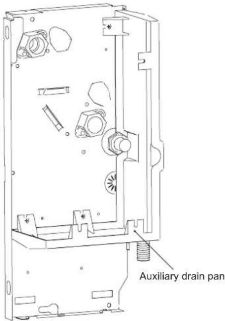
text_image
Auxiliary drain panFigure 5-16
4) How to change the coil from left-hand connection to right-hand connection
Left-hand connection of the coil is adopted by default. You can rotate the coil and change to right-hand connection.
Before installation, you should change the direction of the coil on the ground.
Steps of changing the coil direction:
As shown in Figure 5-17, remove screws ①*2 and ②*2 and then the casing.
As shown in Figure 5-18, remove screws ①*7 to take the drain pan out.
Then, remove screws ②*4 to take the heat exchanger out.
Pull out the temperature sensor plug.
Rotate the coil in the direction as shown in Figure 5-18.
As shown in Figure 5-19, remove screws ①*2 to take the electric box out.
Fasten the screws on the coil.
As shown in Figure 5-19, block the diamond-shaped holes on the side plate (the plate without inlet and outlet pipes) with sponge.
Reverse the direction of drain pan plug.
Re-install the electric box to the side plate without inlet and outlet pipes.
Re-connect the wires.

text_image
② ② ① ① Casing assemblyFigure 5-17 Removal of casing
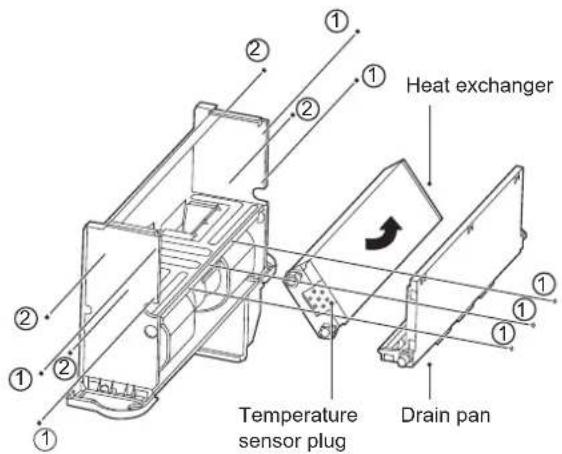
text_image
Heat exchanger Temperature sensor plug Drain panFigure 5-18
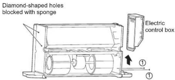
text_image
Diamond-shaped holes blocked with sponge Electric control box ① ①Figure 5-19 Removing the electric control box and blocking the diamond-shaped holes
5) Anti-freezing
The water in the unit may freeze when the unit is left unused in winter.
Drain the water system when appropriate if it is not used over a long period. Or you can simply add proper amount of antifreeze into the water system of the unit.

NOTE
- Mixing water with glycol will affect the unit performance.
- Please pay attention to the safety instructions attached to the glycol container.
5.5 Electrical connection

NOTE
- Make sure that the power supply falls within the range of 220-240V\~1ph 50Hz/60Hz and is able to provide enough wattage for the unit. The power supply system must comply with the current national safety regulations.
- The electrical connection must be completed by qualified professionals and must comply with local laws and regulations. The company is not responsible for personal or property damage resulting from any incorrect electrical connections.
- Provide dedicated and suitable leakage protection device for the unit, with a minimum distance of 3 mm among the wiring contacts. The unit must be grounded reliably.
- Make sure that the power cord has a large-enough cross section to withstand the maximum current required. Never use a damaged cable.
• Perform electrical connections according to the wiring nameplate (Figure 5-20 or Figure 5-22) of the unit.
- Secure the cable using clamps in the electric control box to ensure the safety of the power supply cable and the connection cable.
- Do not pull, step on or squeeze the cable. Do not use nails or staples to secure the power cord.
- The cable must be passed through the knockout hole at the foundation.
- An AC contact switch (with contact separation of at least 3mm) must be installed on the fixed wiring to disconnect the machine from the electrical mains and the omnipolar switch.

flowchart
graph TD
    A["DC FAN"] --> B["CN24"]
    B --> C["CN4"]
    C --> D["CN6"]
    D --> E["CS"]
    D --> F["Infrared Wired controller"]
    D --> G["T1 T2C"]
    D --> H["T2H"]
    D --> I["XP5 XS5 XP4 XS4"]
    I --> J["T1 T2C"]
    D --> K["CN8"]
    K --> L["XP3 XS3"]
    L --> M["T2H"]
    D --> N["CN21"]
    N --> O["XP2 XS2 XP1 XS1"]
    O --> P["T2H"]
    D --> Q["ON/OFF"]
    Q --> R["ON/OFF"]
    Q --> S["-10V+ GND1 0.10V"]
    S --> T["0-10V Wired controller"]
    D --> U["PQ E"]
    U --> V["MODBUS RTU TO UPPER UNIT"]
    U --> W["TO CCM.COMM.BUS"]
    D --> X["CN17"]
    X --> Y["CY2XBA"]
    Y --> Z["BI-directional communication Wired controller"]
    D --> AA["CN29"]
    AA --> AB["XP7 XS7"]
    AB --> AC["Thermostat"]
    AC --> AD["POWER IN ALARM"]
    AC --> AE["POWER IN N"]
    AC --> AF["HI_SPEED MED_SPEED LOW_SPEED COM"]
    AC --> AG["PUMP"]
    AC --> AH["CN37 ALARM PUMP RED LOW COM"]
    AC --> AI["CN16"]
    AC --> AJ["CN26 VALVE-N/VALVE-C/VALVE-H"]
    AC --> AK["BLURED"]
    AC --> AL["Y/G"]
    AC --> AM["XT1 L N POWER IN"]
Figure 5-20 Wiring diagram (unit with inverter motor I-VM; I-VN)
text_image
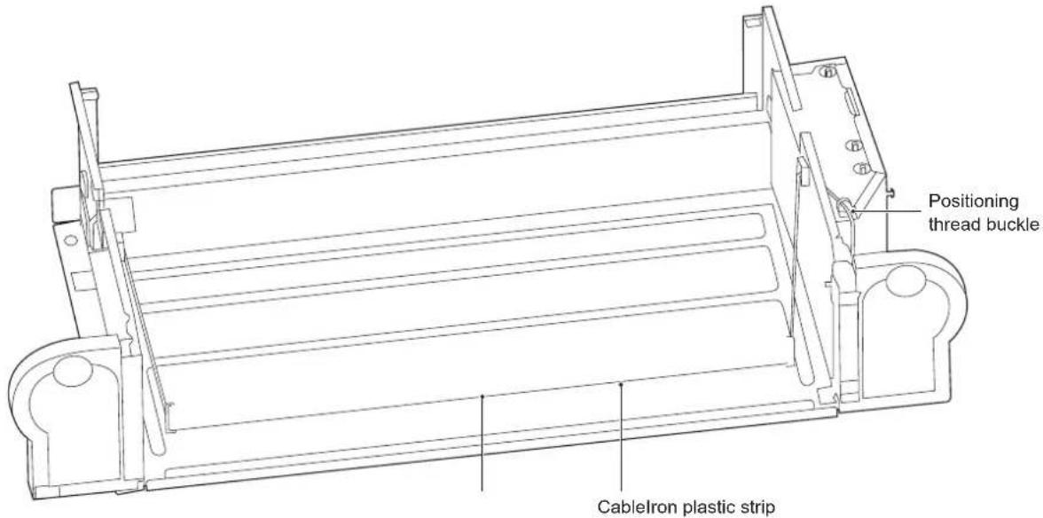
Positioning thread buckle CableIron plastic stripFigure 5-21 Cabling diagram (unit with inverter motor I-VM; I-VN)
text_image
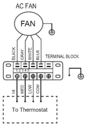
AC FAN FAN BLACK GRAY WHITE BLUE 1 2 3 4 5 TERMINAL BLOCK HI MED LOW COM To ThermostatFigure 5-22 Wiring diagram (version 3V-VM; 3V-VN)
The grounding wire in the electrical control box needs to be longer than the current-carrying wire.
Refer to Table 5-2 and Table 5-3 for the specifications of the power cord and communication wire. A wiring capacity that is too small will cause the electrical wiring to become too hot, and result in accidents when the unit burns and becomes damaged.
Select the wire diameters (minimum value) individually for each unit based on Table 5-3.
The maximum allowable voltage range variation between phases is 2%.
Select the circuit breaker that has a contact separation of no less than 3 mm in all poles to provide full disconnection. MFA is used to select the current circuit breakers and residual current operation breakers:
Table 5-2
| Model | ALL | |
| Power supply | Phase | 1-phase |
| Volt and frequency | 220-240V~50/60Hz | |
| Communication wire between IDU and wired controller * | Shielded ×AWG16-AWG18 | |
| CIRCUIT BREAKER/FUSE (A) 15/15 | ||
Please refer to the corresponding wired controller manual for the wired controller wiring.
Table 5-3
| Rated current of appliance(A) | Nominal cross-sectional area (mm2) | |
| Flexible cords | Cable for fixed wiring | |
| ≤slant 3 | 0.5 and 0.75 | 1 and 2.5 |
| >3 and ≤slant 6 | 0.75 and 1 | 1 and 2.5 |
| >6 and ≤slant 10 | 1 and 1.5 | 1 and 2.5 |
| >10 and ≤slant 16 | 1.5 and 2.5 | 1.5 and 4 |
| >16 and ≤slant 25 | 2.5 and 4 | 2.5 and 6 |
| >25 and ≤slant 32 | 4 and 6 | 4 and 10 |
| >32 and ≤slant 50 | 6 and 10 | 6 and 16 |
| >50 and ≤slant 63 | 10 and 16 | 10 and 25 |
5.6 Startup guide
Machine commissioning or first start-up must be performed by a professional.
Before startup, make sure that the installation and electrical connections are made in accordance with this Manual, and that no unauthorized personnel is near the machine during operation.
1) Before starting the unit, make sure that:
The device is positioned correctly.
The water system's flow and piping are correct.
The water pipe is clean.
The air can flow normally.
The condensate water can flow normally to the drain outlet and the elbow.
The heat exchanger is clean.
The electrical connection is correct.
The connecting cable is secure.
The power supply meets requirements.
The motor works normally within the allowable value.
6 SERVICE GUIDE
Ask a professional technician to repair a faulty unit.
Make sure the power supply is disconnected during repair.
6.1 Troubleshooting
The warranty does not cover the damage caused by dismantling or cleaning of the internal components by unauthorized agents.

WARNING
When any unusual situations arises (burning odour, etc.), stop the unit immediately and turn off the power.
If there is any damage, such as electric shock or fire, caused by the unit, contact your dealer.
The system maintenance must be carried out by qualified maintenance personnel.
| Error Countermeasure | |
| A safety device, such as a fuse, circuit breaker or a leakage circuit breaker is triggered frequently, or the ON/OFF switch is not working properly. | Turn off the main power switch. |
| The operating switch is not functioning normally. | Turn off the power supply. |
| When a centralized controller is used, the unit number is displayed on the user interface, the operating indicator is flickering, and an error code is shown on the screen as well. | Notify the installation personnel and report the error code. |
If the error occurred does not fall within those described in the above table, follow the steps below.
| Error Countermeasure | |
| The system does not run at all. | Check whether there is a power failure. Wait for the power supply to be restored. If a power failure occurs during unit running, the system will restart automatically once the power is restored. |
| The system is running but there is insufficient cooling or heating. | Check whether the air outlet is blocked by any obstacles.If any, remove the obstacles.Check whether the filter is blocked.Check the temperature setting.Check the fan speed settings on the user interface.Check whether the doors and windows are open.Close the doors and windows to shut out wind from the external environment.Check whether there are too many people in the room when the unit is running in Cool mode.Check whether there is too much heat dissipated from any heat source in the room.Check whether there is direct sunlight into the room.Use curtains or blinds.Check whether the angle of air flow is appropriate. |
1) Error code overview
If a centralized controller is used, error codes (if any) will appear on the user interface. Contact the installation personnel and inform them of the error code, unit model and serial number (you can find the information on the nameplate of this unit).
| NO. | Error | Name | Fault Indicator | Bluest Action Error Code | |
| 1 | Error | E?PROM communication error | Steady on | Flashes once every 3 seconds | Buzzes twice every 3 seconds |
| 2 | Error | Room temperature sensor port exception | Steady on | Flashes twice every 3 seconds | Buzzes twice every 3 seconds |
| 3 | Error | Coil sensor (T2C) port exception | Steady on | Flashes 3 times every 3 seconds | Buzzes twice every 3 seconds |
| 4 | Error | Coil sensor (T2C) port exception | Steady on | Flashes 3 times every 3 seconds | Buzzes twice every 3 seconds |
| 5 | Error | DC motor stall fault | Steady on | Flashes 4 times every 3 seconds | Buzzes twice every 3 seconds |
| 6 | Protection | Water level exceeding warning line | Blinking | Flashes once every 3 seconds | Buzzes twice every 3 seconds |
| 7 | Protection | Model protection not set (DIP switch of the unit not listed in the model table) | Blinking | Flashes twice every 3 seconds | Buzzes twice every 3 seconds |
| 8 | Protection | Water temperature protection | Blinking | Flashes 3 times every 3 seconds | Buzzes twice every 3 seconds |
| 9 | Protection | Anti-freezing protection | Blinking | Flashes 4 times every 3 seconds | Buzzes twice every 3 seconds |
| 10 | Protection | Blinking Remote shutdown | Flashes 5 times every 3 seconds | Buzzes twice every 3 seconds |
Refer to Maintenance Manual for troubleshooting.
6.2 Non-unit related faults
The following fault symptoms are not caused by the unit itself:
1) Fault symptom: Fan speed is not consistent with the setting
The fan doesn't respond to the controller. In Cool mode, when the pipe water temperature exceeds the allowable range of room temperature, the fan speed will be maintained at a low level to avoid direct exposure to hot air. In Heat mode, when the pipe water temperature reaches a certain low level, the fan speed will also be maintained at a low level to avoid direct exposure to cold air.
2) Fault symptom: Fan direction is not consistent with the setting
The fan direction is inconsistent with that indicated on the user interface. Swing is a customized function. When Swing is enabled but the fan direction does not change accordingly, it is because the unit is responding to other control instructions.
3) Fault symptom: white fog from a certain unit
This may result from high humidity during cooling operation. If the fan coil interior is dirty, the indoor temperature distribution may be uneven. At this time, you need to clean the inside of the unit. Ask the dealer for information on how to clean the unit. This operation must be carried out by qualified maintenance personnel.
4) Fault symptom: dust and dirt in the unit
This may happen after the unit is used again after being left idle for a long period. This is because there is dust inside the unit.
5) Fault symptom: odour from unit
The unit will absorb odours of rooms, furniture, cigarettes, etc., and then disperse the odours. Odours might occur after small animals enter the unit.
Table 6-1
| Model | 150-I 250-I 350-I | ||
| Air flow volume (m3/h) | 255 | 400 | 595 |
| Cooling capacity (kW) (*) | 1.50 | 2.35 | 3.10 |
| Heating capacity (kW) (**) | 1.57 | 2.60 | 3.50 |
| Sound pressure (dB(A)) (***) | 34 | 29 | 38 |
| Rated input (W) | 15 | 17 | 26 |
| Rated current (A) | 0.18 | 0.20 | 0.26 |
| Standard coil connections | G3/4 | ||
| Condensation drain pipe connection | ODΦ18.5mm | ||
| Power supply | 220-240V~50Hz | ||
| Model | 500-I 700-I 800-I | ||
| Air flow volume (m3/h) | 790 | 1190 | 1360 |
| Cooling capacity (kW) (*) | 4.30 | 5.60 | 7.35 |
| Heating capacity (kW) (**) | 4.00 | 6.00 | 8.05 |
| Sound pressure (dB(A)) (***) | 46 | 5] | 52 |
| Rated input (W) | 50 | 96 | 113 |
| Rated current (A) | 0.49 | 0.85 | 0.95 |
| Standard coil connections | G3/4 | ||
| Condensation drain pipe connection | ODΦ18.5mm | ||
| Power supply | 220-240V~50Hz | ||
(*) Conditions: ambient temperature 27°C DB/19°C WB; water inlet temperature 7°C; water outlet temperature 12°C; maximum speed
(**) Conditions: ambient temperature 20°C DB/15°C WB; water inlet temperature 45°C; water outlet temperature 40°C; maximum speed
(***) The sound pressure level in dB(A) indicates the value measured at 1 m away from an open air outlet.
| Model | 150-3V 250-3V | 350-3V | |
| Air flow volume (m3/h) | 255 | 400 | 595 |
| Cooling capacity (kW) (*) | 1.65 | 2.65 | 3.85 |
| Heating capacity (kW) (**) | 1.85 | 3.05 | 4.10 |
| Sound pressure (dB(A)) (***) | 35 | 34 | 39 |
| Rated input (W) | 35 | 47 | 51 |
| Rated current (A) | 0.15 | 0.20 | 0.22 |
| Standard coil connections | G3/4 | ||
| Condensation drain pipe connection | ODΦ18.5mm | ||
| Power supply | 220-240V~50Hz | ||
| Model | 500-3V | 700-3V | 800-3V |
| Air flow volume (m3/h) | 790 | 1190 | 1300 |
| Cooling capacity (kW) (*) | 4.65 | 6.00 | 7.35 |
| Heating capacity (kW) (**) | 5.20 | 6.15 | 8.20 |
| Sound pressure (dB(A)) (***) | 48 | 50 | 50 |
| Rated input (W) | 91 | 123 | 123 |
| Rated current (A) | 0.40 | 0.53 | 0.53 |
| Standard coil connections | G3/4 | ||
| Condensation drain pipe connection | ODΦ18.5mm | ||
| Power supply | 220-240V~50Hz | ||
The sound pressure level is below 70 dB.
CONTENIDO
text_image
Technical diagram of an electrical enclosure with numbered components and labeled partsnatural_image
Line drawing of a rectangular device with a mesh grille and vertical supports (no text or symbols)natural_image
Pure technical diagram of a heat exchanger or cooling unit with no text, numbers, or symbols
natural_image
Technical line drawing of a rectangular enclosure or storage unit with internal compartments (no text or symbols)text_image
a b d E Fnatural_image
Technical line drawing of a mechanical component with labeled dimensions 'a' (no text or symbols beyond basic lines)
natural_image
Technical diagram of a device rear panel with labeled ports (d, b) and internal components (no text or symbols beyond labels)Figura 5-11 Techo oculto
1 APERÇU DU PRODUIT 01
2 AVERTISSEMENT
text_image
Base ① ① ② Base SemelleFigure 5-3
natural_image
Line drawing of a rectangular device with a mesh grille and vertical supports (no text or symbols)text_image
c d a a SemelleFigure 5-8
natural_image
Pure technical diagram of a heat exchanger or cooling unit with no text, numbers, or symbols
natural_image
Technical line drawing of a rectangular enclosure or enclosure with internal compartments (no text or symbols)text_image
d a a b Figure 5-7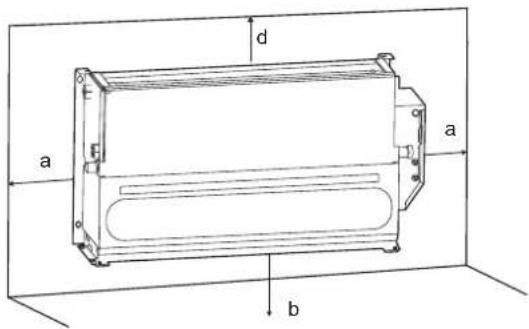
text_image
a b d E FFigure 5-10 Type vertical exposé

natural_image
Technical line drawing of a mechanical component with labeled dimensions 'a' (no text or symbols beyond basic lines)
natural_image
Technical diagram of a device rear panel with labeled ports (d, b) and internal components (no text or symbols beyond labels)Figure 5-11 Plafond encastré
CONDITIONS DE LA GARANTIE
text_image
Parafuso ① Parafuso ②text_image
Caixa control ①text_image
Base Pés Base ① ① ② ②Figura 5-3
natural_image
Line drawing of a portable air conditioner unit with ventilation grilles and cooling fins (no text or symbols)Figura 5-5 Diagrama do teto exposto
text_image
c d a a PésFigura 5-8
natural_image
Technical line drawing of a rectangular enclosure or storage unit with internal compartments (no text or symbols)natural_image
Pure technical diagram of a heat exchanger or cooling unit with no text, numbers, or symbols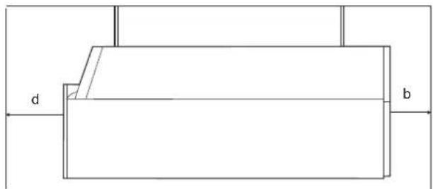
text_image
d bFigura 5-9 Teto exposto
natural_image
Technical line drawing of a mechanical component with labeled dimensions 'a' (no text or symbols beyond basic labels)