
Diamant Plus M - Air Conditioning FERROLI - Free user manual and instructions
Find the device manual for free Diamant Plus M FERROLI in PDF.
| Product type | Air-to-air split air conditioning, heat pump |
| Models | 18-2, 27-3, 28-4 |
| Power supply | 230 V / 1 Ph / 50 Hz |
| Nominal cooling capacity | 5280 W (18-2), 7920 W (27-3), 8200 W (28-4) |
| Nominal heating capacity | 5570 W (18-2), 8210 W (27-3), 8800 W (28-4) |
| EER (cooling) | 3.24 (18-2), 3.23 (27-3), 3.23 (28-4) |
| COP (heating) | 4.01 (18-2), 3.91 (27-3), 4.00 (28-4) |
| Refrigerant | R32, charge from 1.25 to 2.10 kg depending on model |
| Outdoor unit dimensions (L x H x D) | 920 x 615 x 390 mm (18-2) to 1090 x 875 x 500 mm (28-4) |
| Outdoor unit net weight | 38.5 kg (18-2), 51.5 kg (27-3), 62.1 kg (28-4) |
| Noise level (sound pressure at 1 m) | 56 dB(A) (18-2), 54 dB(A) (27-3), 61.5 dB(A) (28-4) |
| Energy efficiency class (cooling) | A++ |
| Energy efficiency class (heating) | A to A++ depending on zone |
| Safety | Automatic circuit breaker, mandatory grounding, protection against thermal and electrical overloads |
| Maintenance and cleaning | Clean filters regularly, do not use direct water jets, call a technician for refrigerant circuit maintenance |
| Spare parts and repairability | Use only original spare parts, any modification voids the warranty |
| General information | Installation in accordance with national standards, respect pipe lengths and height differences, vacuum before commissioning |
Frequently Asked Questions - Diamant Plus M FERROLI
User questions about Diamant Plus M FERROLI
0 question about this device. Answer the ones you know or ask your own.
Ask a new question about this device
Download the instructions for your Air Conditioning in PDF format for free! Find your manual Diamant Plus M - FERROLI and take your electronic device back in hand. On this page are published all the documents necessary for the use of your device. Diamant Plus M by FERROLI.
USER MANUAL Diamant Plus M FERROLI
natural_image
Exterior view of a white ferroli air conditioner unit with visible fan blades and grille (no text or symbols beyond brand logo)
CE
IT MANUALE INSTALLAZIONE E MANUTENZIONE
EN USE AND MAINTENANCE MANUAL
ES MANUAL DE INSTALACIÓN Y MANTENIMIENTO
RO MANUAL DE UTILIZARE ŞI ÎNTREȚINERE
FR MANUEL D'UTILISATION ET D'ENTRETIEN
PL INSTRUKCJA INSTALACJI I KONSERWACJI
PT MANUAL DE INSTALAÇÃO E MANUTENÇÃO
1. CARATTERISTICHE GENERALI 3
1.1 RICEVIMENTO....3
1.2 PREMESSA....3
1.3 PRESENTAZIONE DELLE UNITA 3
1.4 DIRETTIVE EUROPEE 3
1.5 Dati tecnici....4
1.6 DIMENSIONI DI INGOMBRO ....5
1.7 TABELLA ABBINAMENTI 5
1.8 CAMPO APPLICATIVO 6
1.9 DESCRIZIONE UNITÀ....6
1.10 NORME DI SICUREZZA....7
2. INSTALLAZIONE 8
2.1 IMBALLO E IMMAGAZZINAMENTO....8
2.2 CONTENUTO 8
2.3 NOTE GENERALI 8
2.4 LIMITI SU LUNGHEZZA E DISLIVELLO DELLE TUBAZIONI REFRIGERANTI .....9
2.5 INSTALLAZIONE DELL'UNITÀ ESTERNA....10
2.6 KIT SCARICO CONDENSA PER UNITÀ ESTERNA....12
2.7 TUBAZIONI DI COLLEGAMENTO....13
2.8 COLLEGAMENTI FRIGORIFERI 15
2.9 ISOLAMENTO TUBAZIONI....15
2.10 SERRAGGIO TUBAZIONI....15
2.11 OPERAZIONE DI VERIFICA DELLA TENUTA (consigliata).... 16
2.12 OPERAZIONE DI VUOTO (OBBLIGATORIA)....17
2.13 CHIUSURA ZONA ATTACCHI....18
2.14 COLLEGAMENTO ELETTRICO UNITA' ESTERNA.... 18
2.15 COLLEGAMENTI ELETTRICI GENERALITA'....18
2.16 COLLEGAMENTI ELETTRICI....19
3. MESSA IN FUNZIONE....21
3.1 PRIMO AVVIAMENTO....21
3.2 CONTROLLO PRELIMINARE PARTE ELETTRICA....21
3.3 CONTROLLO PRELIMINARE PARTE FRIGORIFERA....21
3.4 ACCENSIONE....21
4. SICUREZZA ED INQUINAMENTO....21
natural_image
Technical line drawing of a mechanical device with labeled dimensions H and D (no text or symbols beyond labels)
natural_image
Technical line drawing of a front-mounted air conditioner unit with fan blades and mounting base (no text or symbols)fig. 1 -
| MOD. 18-2 27-3 28-4 UM | |||
| D 333 363 420 mm | |||
| H 554 702 810 mm | |||
| W 800 845 946 mm | |||
| W1 70 69 84 mm |
1.7 TABELLA ABBINAMENTI
fig. 2 -
1.10 NORME DI SICUREZZA
natural_image
Illustration of a wall-mounted air conditioner unit with airflow direction indicated by an upward arrow (no text or symbols)fig. 3 -
2.2 CONTENUTO
fig. 9 -
natural_image
Line drawing of a dual air conditioner unit with fan and water drop (no text or symbols)fig. 10 -
natural_image
Line drawing of a mechanical device with a cylindrical base and a vertical shaft (no text or symbols)fig. 12 -
natural_image
Line drawing of a hand holding a small cylindrical object with a pointed tip (no text or symbols)fig. 13 -

fig. 14 -
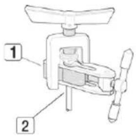
fig. 15 -

natural_image
Technical line drawing of a cylindrical mechanical component with a flanged end (no text or symbols)fig. 16 -
Tabella. 1 - rif "fig. 14 -"
| Diametro nominale (") | Diametro esterno (mm) ∅ | Spessore tubo (mm) | A (mm) |
| 1/4 6,35 0,80 | 1,5 ~ 2,0 | ||
| 3/8 9,52 0,80 | 1,5 ~ 2,0 | ||
| 1/2 12,70 0,80 | 2,0 ~ 2,5 | ||
| 5/8 15,88 1,00 | 2,0 ~ 2,5 |
Tabella. 2 - rif. "fig. 17 -"
| Diametro nominale (") | Diametro esterno (mm) ∅ | Spessore tubo (mm) | A (mm) | ||||
| A B C D | Spessore bocchettone | ||||||
| 1/4 6,35 | 0,80 9,1 9,2 6,5 13 17 | ||||||
| 3/8 9,52 | 0,80 13,2 13,5 9,7 20 22 | ||||||
| 1/2 | 12,70 | 0,80 16,6 | 16,0 12,9 | 23 26 | |||
| 5/8 | 15,88 | 1,00 19,7 | 19,0 16,0 | 25 29 | |||

fig. 17 -
natural_image
Technical line drawing of a mechanical connector assembly (no text or symbols)fig. 18 -
2.8 COLLEGAMENTI FRIGORIFERI
fig. 19 -
fig. 20 -
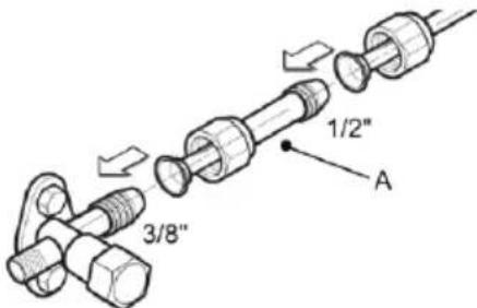
fig. 21 -
natural_image
Diagram of a mechanical device with gears and shafts, no visible text or symbolsfig. 22 -
natural_image
Line drawing of a desktop air conditioner unit with fan and cooling tower (no text or symbols)fig. 25 -
2.14 COLLEGAMENTO ELETTRICO UNITA' ESTERNA
natural_image
Line drawing of a large air conditioner unit with fan and control panel (no text or symbols)fig. 26 -
2.15 COLLEGAMENTI ELETTRICI GENERALITA'
3. SETTING AND WORK....42
3.1 STARTING UP FOR THE FIRST TIME 42
3.2 PRELIMINARY CHECKS ON THE ELECTRICAL PART 42
3.3 PRELIMINARY CHECKS ON THE COOLING PART 42
3.4 STARTING....42
4. SAFETY AND POLLUTION 42
4.1 GENERAL CONSIDERATIONS .... 42
1. GENERAL SPECIFICATIONS
1.1 CONSIGNMENT OF THE MACHINE
As soon as the machine is consigned, it is essential for the user to make sure that he has received all the items indicated on the consignment note and that the machine has not been damaged during transport. If damage is discovered, allow the forwarding agent to ascertain its entity and also inform our seller. Only in this way will you be able to receive the missing items or reimbursement of damages within the shortest possible time.
1.2 FOREWORD
This machine has been designed and built for air conditioning purposes alone and must only be used for that purpose. Even the best of machines can only operate properly if they are correctly used and kept fully efficient. Please read this instruction manual carefully and consult it should difficulties arise when the machine is used. Remember that our after sales-service, organized in collaboration with our dealers, is always at your disposal if advice or interventions are required.
1.3 PRESENTATION OF THE UNIT
Air conditioners/split type air conditioners must be connected to an outdoor unit. This model range can be coupled to both outdoor units like the Mono-Split type, coupled to only one indoor unit, or the Multi-Split type that can be coupled to two or more indoor units. The series is available in the heat pump version with R32.
Appliance filled with flammable gas R32.
Please notice that the unit is filled with flammable gas R32. Inappropriate treatment of the unit involves the risk of severe damages of people and material. Details to this refrigerant are found in section "SAFETY AND POLLUTION" on page 41.
1.4 DECLARATION OF CONFORMITY
The manufacturer declares that the machines described in this instruction manual meet the requirements of the following directives and subsequent modifications.
- Low voltage directive 2014/35/EU;
• Electromagnetic compatibility directive 2014/30/EU;
• RAEE directive 2012/19/EU;
• RoHS directive 2011/65/EU;
• ErP directive 2009/125/CE
• Energy labelling regulation EU 2017/1369;
It conforms to what is stated in the legislation
• EN 60335-2-40

1.5 TECHNICAL DATA
| MODEL 18-2 27-3 28-4 UM | |||||
| Combination condition 9 + 9 9 + 9 + 9 7 + 7 + 7 - | |||||
| Power Supply | 230/1/50 V-Ph-Hz | ||||
| Cooling Capacity * | Rated | 5280 7920 8200 W | |||
| Min-Max | 1130-5570 2960-8500 2050-9850 W | ||||
| Power Input at Cooling * | Rated | 1630 2450 2540 W | |||
| Min-Max | 150-2000 | 235-3220 | 890-3180 | W | |
| Rated current at Cooling * | 7,10 13,70 | 11,3 | A | ||
| EER ref. Standard EN14511 * | Rated | 3,24 | 3,23 | 3,23 | WW |
| SEER ref. Standard EN14825 | 6,10 | 6,10 | 6,10 | WW | |
| PdesignC | 5,3 | 7,9 | 8,2 kW | ||
| Heating Capacity * | Rated | 5570 8210 8800 W | |||
| Min-Max | 1795-5865 2040-9380 | 2345-10560 | W | ||
| Power Input at Heating * | Rated | 1390 2100 2200 W | |||
| Min-Max | 300-1650 | 310-2890 | 770-2750 | W | |
| Rated current at Heating * | 6,1 | 12,5 | 9,8 | A | |
| COP ref. Standard EN14511 * | Rated | 4,01 | 3,91 | 4,00 | WW |
| Climate Zone ref. Standard EN14825 | A (average) | Type | |||
| SCOP * ref. Standard EN14825 | 3,80 | 4,00 | 3,80 | WW | |
| PdesignH | 4,8 | 5,6 | 6,5 kW | ||
| Temp balance Tbiv | -7,0 | -7,0 | -7,0 °C | ||
| Temp use limit Tol | -15,0 | -15,0 | -15,0 | °C | |
| Efficiency class Standard 626/2011 Directive 2009/125/CE | Cooling | A++ | A++ | A++ | \ |
| Heating | A | A+ | A | \ | |
| Climate Zone ref. Standard EN14825 | B (warmer) | Type | |||
| SCOP * ref. Standard EN14825 | 4,80 | 5,10 | 4,60 | WW | |
| PdesignH | 4,9 | 6,1 | 6,9 kW | ||
| Temp balance Tbiv | 2,0 | 2,0 | 2,0 | °C | |
| Temp use limit Tol | 2,0 | 2,0 | 2,0 | °C | |
| Efficiency class Standard 626/2011 Directive 2009/125/CE | Cooling | A++ | A++ | A++ | \ |
| Heating | A++ A+++ | A++ | \ | \ | |
| Outdoor unit air flow | 2200 2700 3800 m | ^3/h | |||
| Sound pressure level outdoor unit ** | 56 | 54 | 61,5 dB(A) | ||
| Sound power level outdoor unit | 65 | 67 | 67 | dB(A) | |
| Refrigerant | R32 | Type | |||
| GWP | 675 | tCO2 eq. | |||
| Charge | 1,25 | 1,72 | 2,10 | kg | |
| Packing dimension outdoor unit | W | 920 | 965 | 1090 | mm |
| H | 615 | 775 | 875 | mm | |
| D | 390 | 395 | 500 | mm | |
| Net weight outdoor unit | 38,5 | 51,5 | 62,1 | kg | |
| Liquid connection (qty x Diameter) | 2x1/4" | 3x1/4" | 4x1/4" | n° x inch | |
| Gas connection (qty x Diameter) | 2x3/8" | 3x3/8" 3x3/8" + | 1x1/2" n° x inch | ||
Note:
External air temperature = 35°CDB • Ambient air temperature = 27°CDB / 19°CWB
External air temperature = 7°CDB / 6°CWB • Ambient air temperature = 20°CDB
*: Data referred to the nominal matching reported
** Sound pressure level detected at a distance of 1 m.
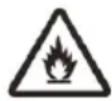
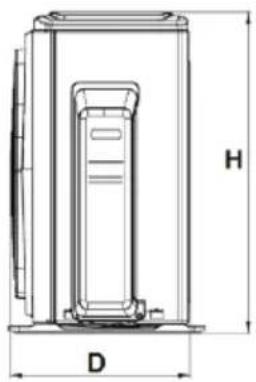
1.6 OVERALL DIMENSIONS
natural_image
Technical line drawing of a fan-shaped air conditioning unit (no text or symbols)fig. 1 -
| MOD. 18-2 27-3 28-4 UM | |||
| D 333 363 420 mm | |||
| H 554 702 810 mm | |||
| W 800 845 946 mm | |||
| W1 70 69 84 mm |
1.7 MATCHING TABLE
The table below shows the possible combinations between the outdoor unit and different sizes of indoor units.
| OUTDOOR UNIT | Internal units connected | ||||||
| 1 2 3 4 | |||||||
| 18-2 | 7K | 7K+7K 7K+9K | not expected not expected | ||||
| 9K | 7K+12K | 9K+9K | |||||
| 12K | 9K+12K | 12K+12K | |||||
| 27-3 | non previsto | 7K+7K 7K+9K | 7K+7K+7K 7K+7K | 7K+9K | 7K+7K | +12K | not expected |
| 7K+12K | 7K+18K | 7K+7K+18K | 7K+9K+9K | 7K+9K+12K | |||
| 9K+9K | 9K+12K | 7K+9K+18K | 7K+12K+12K | 9K+9K+9K | |||
| 9K+18K | 12K+12K | 9K+9K+12K | 9K+12K+12K | 12K+12K+12K | |||
| 12K+18K | \ | \ | \ | \ | |||
| 28-4 | non previsto | 7K+7K | 7K+9K | 7K+7K+7K | 7K+7K+9K | 7K+7K+12K | 7K+7K+7K+7K |
| 7K+12K | 7K+18K | 7K+7K+18K | 7K+9K+9K | 7K+9K+12K | 7K+7K+7K+12K | ||
| 9K+9K | 9K+12K | 7K+9K+18K | 7K+12K+12K | 7K+12K+18K | 7K+7K+9K+9K | ||
| 9K+18K | 12K+12K | 9K+9K+9K | 9K+9K+12K | 9K+9K+18K | 7K+7K+12K+12K | ||
| 12K+18K | 18K+18K | 9K+12K+12K | 9K+12K+18K | 12K+12K+12K | 7K+9K+9K+12K | ||
| / | / | / | / | / | 9K+9K+9K+9K | ||
1.8 APPLICATION FIELD
We recommend to use of the unit under the conditions described below.
| Operating mode Parameter | Inner side Outer side | U.M | ||||
| B.S B.U | B.S B.U | |||||
| Cooling | Maximum inlet air temperature | 32 23 50 | (°C) | |||
| Minimum inlet air temperature | 17 16 -15 | (°C) | ||||
| Heating | Maximum inlet air temperature | 30 \ 24 | 20 (°C) | |||
| Minimum inlet air temperature | 0 \ -15 | -13 (°C) | ||||
| All | Supply Voltage | 230±10% (V) | ||||
| Supply Frequency | 50±2 (Hz) | |||||
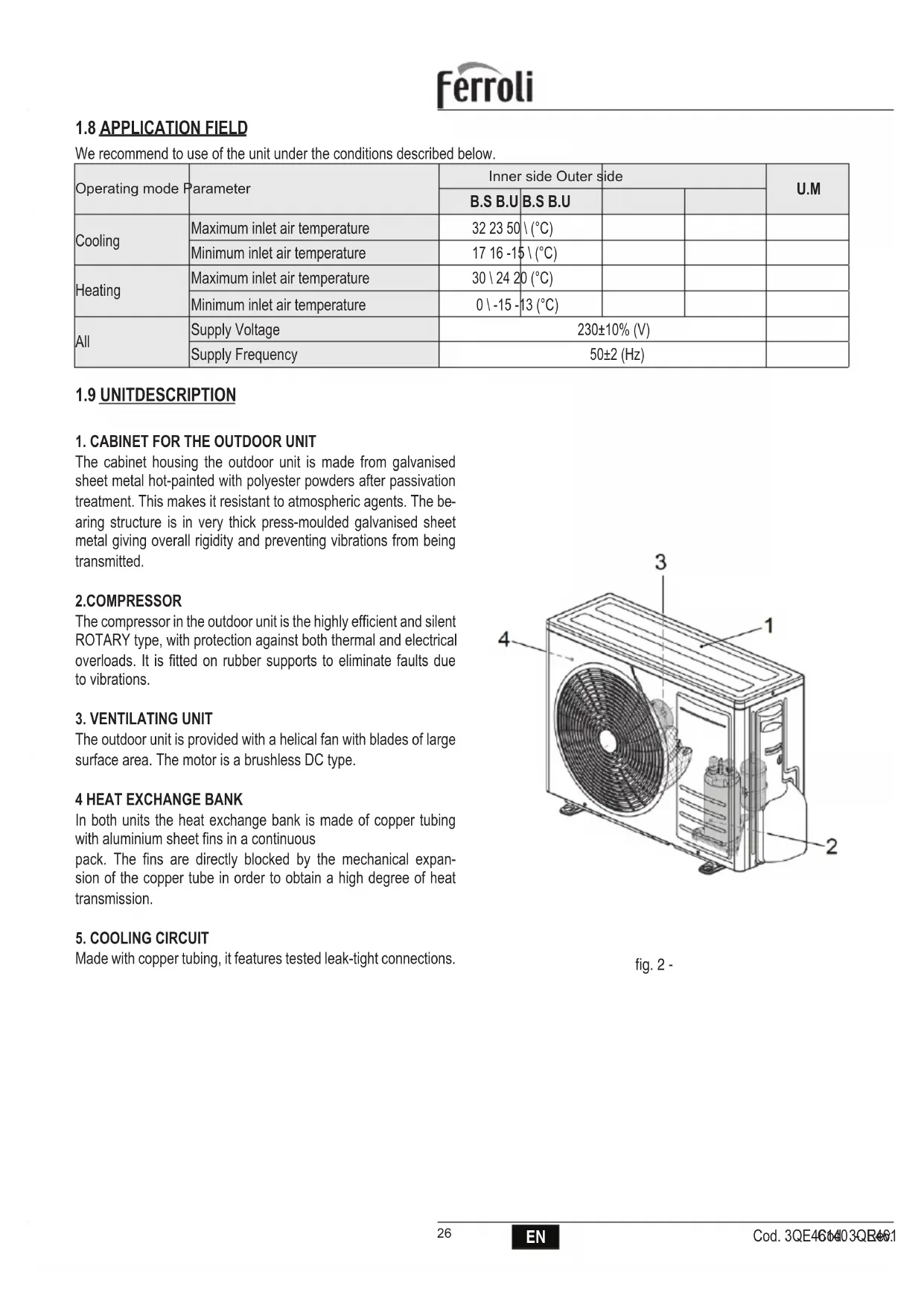
1.9 UNITDESCRIPTION
1. CABINET FOR THE OUTDOOR UNIT
The cabinet housing the outdoor unit is made from galvanised sheet metal hot-painted with polyester powders after passivation treatment. This makes it resistant to atmospheric agents. The bearing structure is in very thick press-moulded galvanised sheet metal giving overall rigidity and preventing vibrations from being transmitted.
2.COMPRESSOR
The compressor in the outdoor unit is the highly efficient and silent ROTARY type, with protection against both thermal and electrical overloads. It is fitted on rubber supports to eliminate faults due to vibrations.
3. VENTILATING UNIT
The outdoor unit is provided with a helical fan with blades of large surface area. The motor is a brushless DC type.
4 HEAT EXCHANGE BANK
In both units the heat exchange bank is made of copper tubing with aluminium sheet fins in a continuous
pack. The fins are directly blocked by the mechanical expansion of the copper tube in order to obtain a high degree of heat transmission.
5. COOLING CIRCUIT
Made with copper tubing, it features tested leak-tight connections.
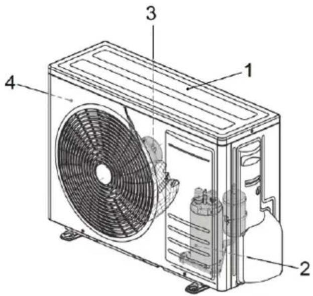
fig. 2 -
1.10 SAFETY REGULATIONS
Strictly comply with the following regulations to prevent injury to the operator or damage to the machine.
- The unit installation must be done according to the installation rules valid in your country.
- This installer's handbook, the user manual and the wiring diagrams are integral part of the machine. They must be kept with care and be ready to hand should the operators require them for consultation.
- Failure to comply with the instructions in this manual and inadequate installation of the conditioner may void the certificate of guarantee. Moreover, the Manufacturer shall not be liable for direct and/or indirect damages due to incorrect installation or for damages caused by conditioners installed by inexpert or unauthorized personnel.
• Work in a clean, uncluttered place when installing the equipment. - It is absolutely forbidden to touch moving parts or to move between the same.
• Before starting the conditioner, make sure that the various components and the entire system are in perfect and safe conditions. - Strictly comply with the routine maintenance operations.
- Insist on genuine spare parts. Failure to do so will void the guarantee.
- Do not remove or tamper with the safety devices.
- Disconnect the electric power source before proceeding with any work on the machine.
- Do not place anything on the top part of the units.
- Do not push items through the protective fan grilles or allow objects to drop through.
• The bank surface is sharp. Do not touch it without protective gloves.
• Carefully read the stickers on the machine, never cover them and replace them immediately should they be damaged. - Do not use the machine in an explosive atmosphere.
• The power line must be regularly grounded. - If the power cable has been damaged, stop the machine if it is operating, and have the cable immediately replaced by an authorized technician.
- The machine must be stored at a temperature between -25^ and 55^ .
- Use a powder extinguisher in the event of a fire outbreak. Do not use water.
- If the machine operates in an abnormal way, make sure that this does not depend on failure to carry out routine maintenance. Failing this, ask to have the machine checked by a specialized technician.
• If the outdoor unit must be dismantled, it is advisable to have the job done by an authorized technical service centre. - The machine must not be dumped if it is to be scrapped since it contains materials that must be recycled or disposed of by authorized centres.
- Do not wash the machine with direct or pressurized jets of water or with corrosive substances.
The Manufacturer and after-sales service network are at your disposal for prompt and accurate technical assistance and for anything else able to ensure the best operation and achieve the utmost efficiency from your machine.
2. INSTALLATION
2.1 PACKING AND STORING
All machines are packed in cardboard boxes specific for each unit.
The indications required to correctly handle the appliance while storing and installing it are written on the packing. The storage temperature must be between -25°C and 55°C.
Note: Do not throw the packing away exteriors to avoid environmental pollution.
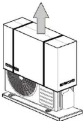
Once the place in which the unit is to be installed has been chosen (see the relative sections) proceed as follows to unpack the two units:
Outdoor unit:
- Cut the two nylon straps.
2.Remove the cardboard box.
3.Remove the nylon wrapping
natural_image
Illustration of a refrigerated air conditioner unit with airflow direction indicated (no text or symbols)fig. 3 -
2.2 CONTENT
Packagings contain the units as well as accessories and technical documentation for the use and installation. Check that the following components are present.
| Description Image Qty Notes | |||
| Condensation drain fitting | 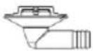 | 1 | |
| Pipe adaptorator | 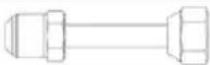 | 1 or 2 a in accordance with the model | to be use in case of indoor units 18 connection |
| Manuals |  | 1 | Installation manual |
2.3 GENERAL NOTES
In order to ensure the correct operation of the air conditioner, always follow the designation of the units ("fig. 4 -" 1-2-3 etc.) while making cooling and electrical connections.
The electrical connection identified with 1 (2, 3, etc.) must correspond to the cooling line no.1 (2, 3, etc.).
Cooling lines 1-2-3 etc. can be easily identified by looking at the labels on the couplings of the outdoor unit.
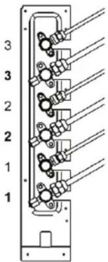
fig. 4 -
2.4 LIMITS TO THE LENGTH AND HEIGHT DIFFERENCE OF REFRIGERANT PIPES
The length of the refrigerant pipes between the indoor and outdoor units must be as short as possible and is in any case limited by compliance with the maximum height difference values between the units.
Diminution of the difference in height between the units (H+,H-) and of the pipe lengths (L) will limit the load losses, consequently increasing the overall efficiency of the machine.
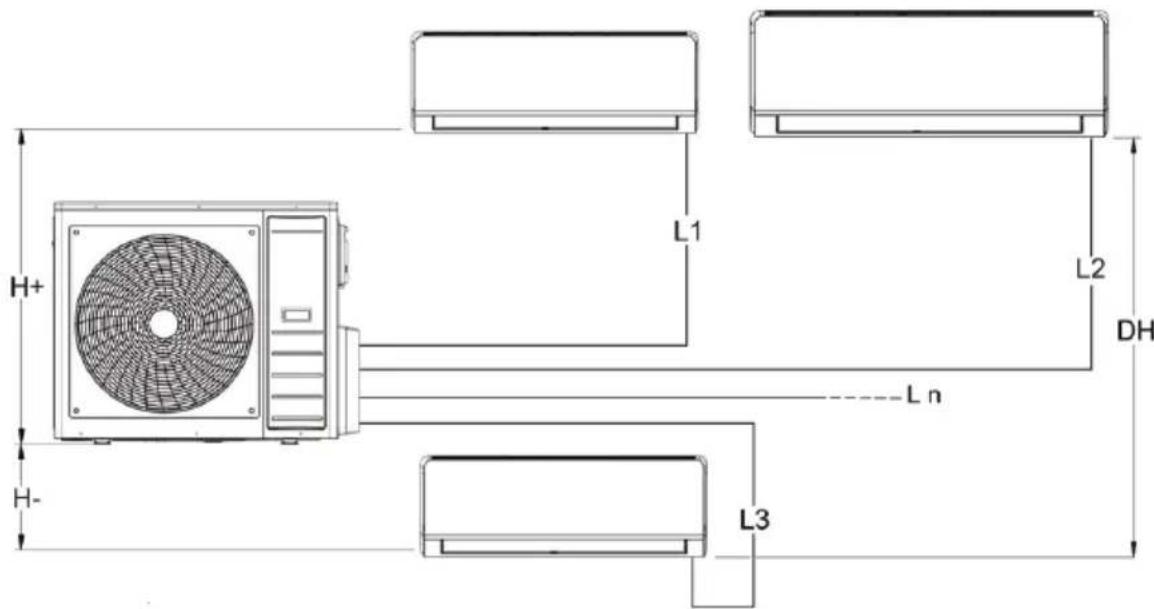
fig. 5 -
Comply with the limits given in the following tables.
| Model UM 18-2 27-3 28-4 | |||||||||||
| Liquid connection | “ 1/4” | 1/4" 1/4" | 1/4" 1/4" | 1/4" 1/4" | 1/4" 1/4" | ||||||
| Gas connection | “ 3/8” | 3/8" 3/8" | 3/8" 3/8" | 3/8" 3/8" | 3/8" 3/8" | ||||||
| Max length | m 40 | 60 80 | |||||||||
| Maximum single unit length | m 25 | 30 35 | |||||||||
| Max difference level | H+ | m 15 | 15 15 | ||||||||
| H- | m 15 | 15 15 | |||||||||
| DH | m 10 | 10 10 | |||||||||
| Maximum length with standard charge | m 7,5 | 7,5 7,5 | |||||||||
| Additional refrigerant charge per meter | g 12 | 12 12 12 | 12 12 12 | 12 24 | |||||||
Contact our technical department for the required modifications if the units must operate beyond the specifications given above.
2.5 INSTALLING THE OUTDOOR UNIT
Bear in mind the following when choosing the place in which the outdoor unit is to be installed:
- Before installing the air conditioner make sure that it has been transported in an upright position. If this is not the case, position it correctly and wait at least two hours before starting it.
- If possible, place the unit away from rain and direct sun light in a sufficiently ventilated area.
- Set it in a vibration and noise free position of adequate load bearing capacity.
- Position it so that the noise and air flow, while operating, do not disturb the neighbours.
- Position it respecting the minimum distances from walls, furniture or other objects ("fig. 6 -" e "fig. 7 -").
- If it is installed on the ground, avoid areas where water may collect or fall, gutters, etc.
- In locations that are subject to frequent snowfalls or where the temperature remains below 0°C for lengthy periods, set the unit on a 20-30 cm thick concrete base to prevent snow from lying around the machine.
- During winter periods, the heat pumps produce condensation that drips on the supporting surface forming annoying and/or unpleasant puddles. To avoid this, use the condensation drain fitting kit as indicated in the relative section.
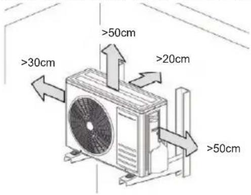
Note: The air conditioner must not be surrounded by more than three walls to ensure sufficient ventilation to allow the appliance to operate correctly.
If the installation does not allow direct access to the unit, it is recommended to remove the rear protection grille. This is to allow the air flow and avoid possible ice build up during winter operation.
Remove the packing following the instructions given in the "Packaging and storing" section and, using a fork lift truck, lift the unit and position in the place desired. While moving the unit, keep it upright without tilting it. High protection against the transmission of vibrations is achieved by placing appropriate dowels made of impact-resistant material (neoprene etc.) between the support feet of the unit and the floor.
For this purpose, the distances for the positioning of vibration dampers are listed below. In any event, consult the specialized catalogues when choosing the support feet.
fig. 8 -
Mod. 18-2 27-3 28-4 U.M
| W | 800 845 946 mm |
| D | 333 363 420 mm |
| l1 | 514 540 673 mm |
| w1 | 340 350 403 mm |
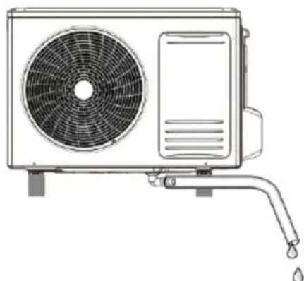
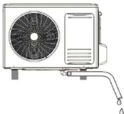
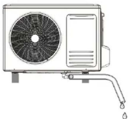
2.6 CONDENSATION DRAIN KIT FOR OUTDOOR UNIT
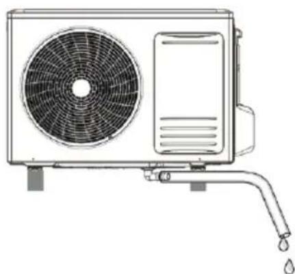
In the outdoor units with heat pump, condensation is created when running in heating mode. In this case it may be necessary to convey the condensation towards a drain.
To do so, proceed as follows:
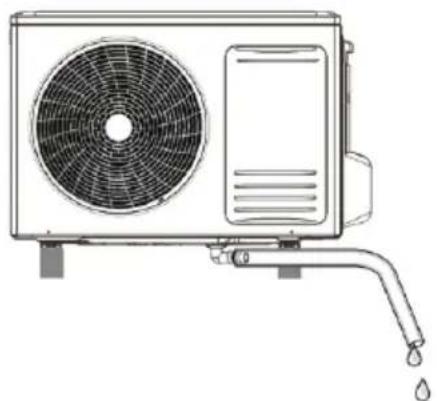
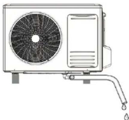
- Fix the supplied fitting (part 1 - "fig. 9 -") in the appropriate hole (part 2 - "fig. 9 -") on the base of the outdoor unit. The fastening is carried out by inserting the shaped part of the fitting in the hole.
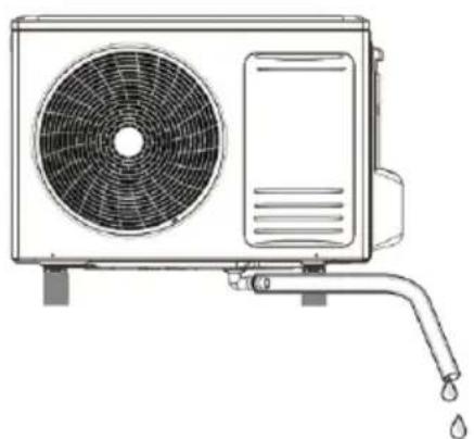
- Connect the fitting ("fig. 10 -") to a sufficiently resistant rubber hose (so that it is not deformed or throttled in any way).
- Secure it with a hose clip and route it to an appropriate drain.
- Make sure that the pipe slopes enough to allow the condensation to flow down naturally.
- Check the efficiency of the drain by pouring a small amount of water directly into the tray of the outdoor unit.
N.B.: The kit is supplied with the machine.
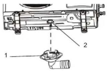
fig. 9 -
natural_image
Line drawing of a dual air conditioner unit with fan and water drop (no text or symbols)fig. 10 -
2.7 CONNECTION PIPES
The pipes are wound and already flared at both ends. The dimensions are those given in the "LIMITS TO THE LENGTH AND HEIGHT DIFFERENCE OF REFRIGERANT PIPES" on page 29.
Route the coolant pipes as required, with as few bends possible. Use an appropriate pipe bender and comply with a minimum bending radius to prevent them from being squashed. Remember that the bending radius must not be less than 3.5 times the outer diameter of the pipe ("fig. 11 -").
If you do not wish to cut off any excess pipe after routing, wind it up so that the coil axis is horizontal.
Bear the following indications in mind when installing the pipes:
• Take care to unwind the pipe in the direction in which it was wound.
- Wrap the two pipes together with tape before passing them through the holes in the wall to prevent the insulation from being damaged and dust from infiltrating. To facilitate this operation, it is advisable to insert a piece of PVC pipe of a suitable diameter and the same length as the wall thickness, into the hole in the wall.
Adequate materials must be selected since the operating pressure values are sensibly higher than those of the R32 refrigerant. The following table gives the thickness values of the recommended copper pipes in relation to the nominal diameters of the connecting lines. Do not
use pipes whose thickness is less than 0.8mm.
If the pipes are longer than the effective requirements, they can be cut and re-flared
by operating in the following way:
-
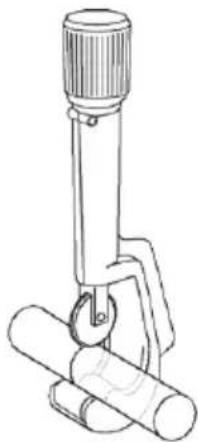
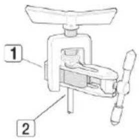
Pipe cutting. Use a pipe cutter ("fig. 12 -"). Proceed with care when cutting the pipe so as to prevent it from becoming deformed. Cut the pipe to the required length (the cut must be horizontal).
-
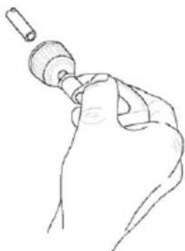
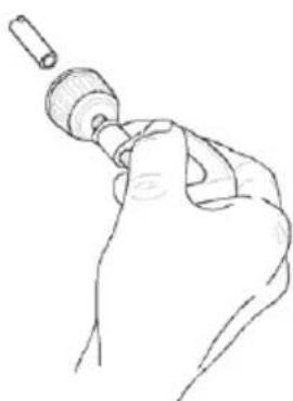
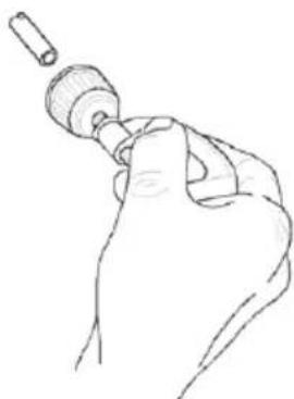
2.How to remove burrs or splinters. Refrigerant could leak if the surface of the flare is warped or splintered. It is advisable to remove the burrs by holding the pipe end downwards ("fig. 13 -"). Remove the burrs and trim the surface of the cut edge.
-
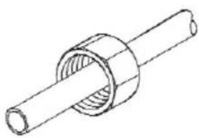
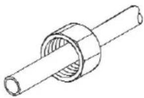
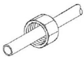
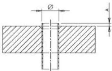
Insert the union. Remember to insert the union before flaring the pipe ("fig. 16 -").
-
Pipe flaring. Make sure that the pipe and swaging machine are clean. Remember to comply with the instructions in the following tables ("Re-flanging thickness" and "Flare and Union dimensions") when flaring the pipes. Clamp the pipe (2 "fig. 15 -") in a vice (1 fig. 16 -) and begin to flare it (it is best to place a drop of refrigerating oil between the rubbing parts).
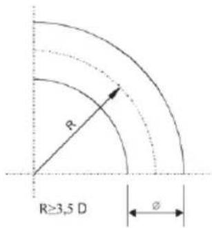
fig. 11 -

natural_image
Line drawing of a mechanical device with a cylindrical base and a flanged top (no text or symbols)fig. 12 -

natural_image
Line drawing of a hand holding a small cylindrical object, possibly a tool or device (no text or symbols present)fig. 13 -

fig. 14 -
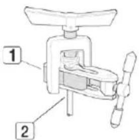
fig. 15 -
natural_image
Technical line drawing of a mechanical component with cylindrical shaft and flanged end (no text or symbols)fig. 16 -
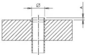
Tabella. 1 - ref. "fig. 14 -"
| Pipe nominal size (") | External diameter (mm) ∅ | Pipe wall thickness (mm) | A (mm) |
| 1/4 6,35 0,80 | 1,5 ~ 2,0 | ||
| 3/8 9,52 0,80 | 1,5 ~ 2,0 | ||
| 1/2 12,70 0,80 | 2,0 ~ 2,5 | ||
| 5/8 15,88 1,00 | 2,0 ~ 2,5 |
Tabella. 2 - ref. "fig. 17 -"
| Pipe nominal size (") | External diameter (mm) | Pipe wall thickness (mm) | A (mm) | ||||
| A B C D | Union fitting thickness (mm) | ||||||
| 1/4 6,35 | 0,80 9,1 9,2 | 6,5 13 17 | |||||
| 3/8 9,52 | 0,80 13,2 13,5 | 9,7 20 | 22 | ||||
| 1/2 | 12,70 | 0,80 | 16,6 | 16,0 | 12,9 | 23 | 26 |
| 5/8 | 15,88 | 1,00 | 19,7 | 19,0 | 16,0 | 25 | 29 |

fig. 17 -
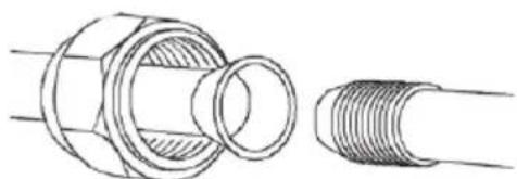
Note: Make sure that the oil used to lubricate the flare is the same type or compatible with the oil used in the refrigerating circuit. The following results are obtained if flaring has been carried out correctly ("fig. 18 -"):
- Smooth and mirrored surfaces.
- Smooth edges.
- Flared sides of uniform length.
Note: Take care to prevent swarf, dust or other impurities from dropping inside the pipes since these would clog the cooling circuit at the capillary, causing the system to block or the compressor to seize.
natural_image
Technical line drawing of a mechanical connector assembly (no text or symbols)fig. 18 -
2.8 COOLING CONNECTIONS
Comply with the following indications when connecting the cooling pipes:
- Match the ends of the previously flared pipe (part.1 "fig. 19 -") with those of the connections on the indoor units or on the cocks of the outdoor units (part.2 "fig. 19 -").
- Tighten the union by hand and then torque it with the aid of an adequate wrench (it is advisable to use a fox wedge to prevent tensions from being created on the pipes).
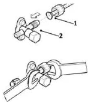
fig. 19 -
For the connection with model 18 indoor units it is necessary to use pipe diameter adaptation kits ("fig. 20 -"). These kits (part A - "fig. 21 -") are supplied with outdoor units and must be connected to the cock on the outdoor unit, and then to the 1/2" pipe required for the connection with the indoor unit.
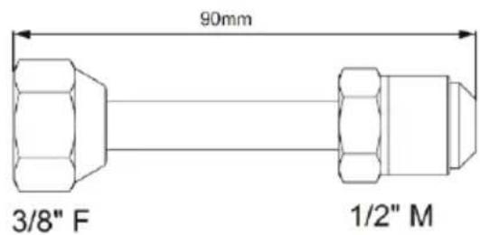
fig. 20 -

fig. 21 -
2.9 PIPE INSULATION
To ensure system efficiency and its correct operation it is necessary to use pre-insulated cooling connection lines easily available on the market. Pay also attention to the connection points according to what described.
Use thermal insulating tape to tie the hoses, from the area connecting the outdoor unit cocks to the upper end of the hose in correspondence of the wall entry point. ("fig. 22 -")
natural_image
Diagram of a mechanical device with gears and shafts, no text or symbols presentfig. 22 -
2.10 PIPE CLAMPING
Make sure that the connecting zone is free from dust and dirt.
• Make sure that the flare and connection are perfectly aligned.
- Tighten the union first by hand and then with an adequate torque wrench.
Leaks could occur if the parts are insufficiently tightened, while the flare could be damaged if it is tightened too strongly.
The table below lists the torques recommended for the various pipe diameters
| Pipe nominal size (") External diameter (mm) ∅ | Tightening torque(N x m) |
| 1/4 6.35 15-20 | |
| 3/8 9.52 30-40 | |
| 1/2 12.70 45-55 | |
| 5/8 15.88 60-65 |
2.11 TIGHTNESS CHECK (RECOMMENDED OPERATION)
Before setting the system in a vacuum, it is advisable to make sure that the cooling circuit is tight, including the connecting joints between the pipes and the indoor unit. Proceed in the following way:
- With the service valves of the outdoor unit completely shut, remove the cap from the service tap (part 1 - "fig. 23 -") and the union (part 2 - "fig. 23 -") of the gas valve (the larger one)
- Connect the service valve to a monometric unit plus nitrogen bottle (N2).
- Pressurize the system to a maximum 30 bar using the nitrogen in the bottle.
- Use liquid soap to check that the joints are tight.
Keep the bottle vertical during the pressurizing operation to prevent liquid nitrogen from infiltrating into the system!
- Check all the connection joints on both the outdoor and indoor units to make sure that they are tight. Bubbles will form if leaks are present. If bubbles appear, make sure that the unions have been tightened and that the flares are the right shape.
- Wipe off the liquid soap with a rag.
- Reduce the pressure of the nitrogen in the circuit by loosening the charge pipe from the bottle.
• Having reduced the pressure, disconnect the nitrogen bottle.
Perform the leak test for all connection lines (i.u.a, i.u.b, i.u.c).
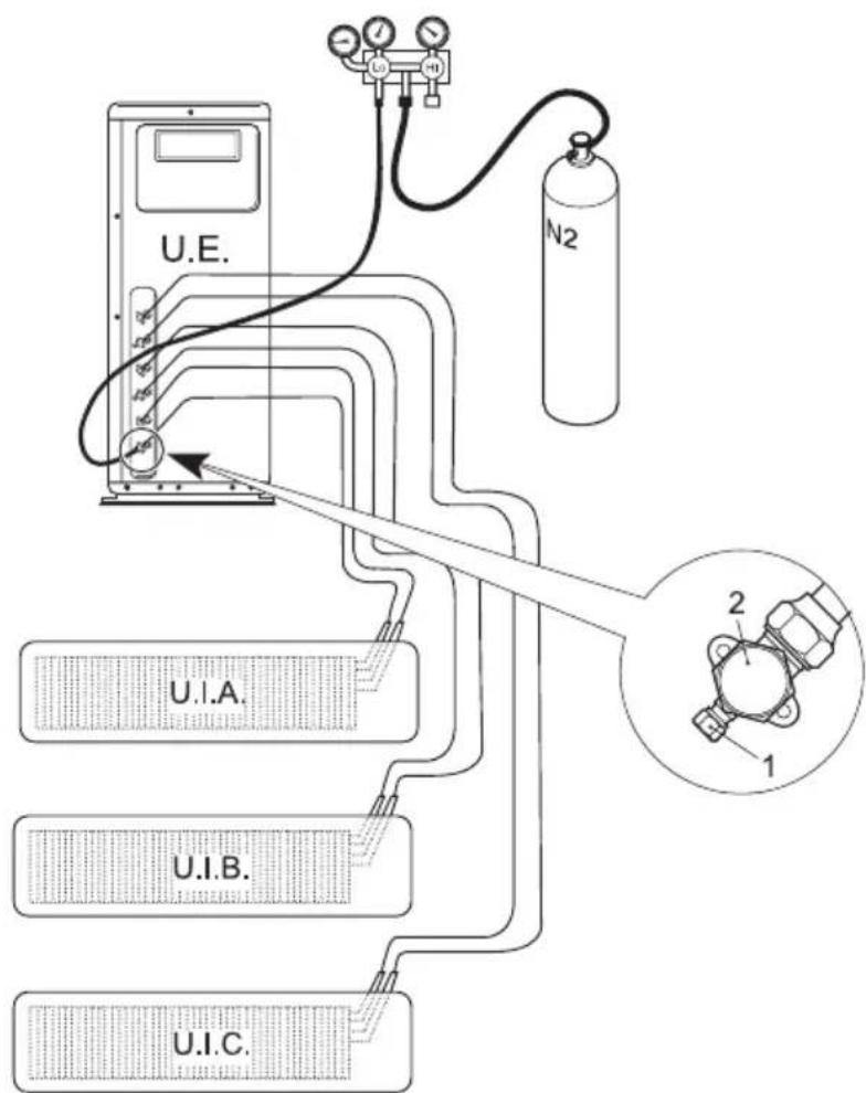
fig. 23 -
Air and humidity in the cooling circuit impair the operation of the unit with effects such as:
- Increased pressure.
- Reduced efficiency.
- Formation of ice on the capillary and subsequent blockage of the same.
• Corrosion in the circuit.
This is why a vacuum must be created in the connection pipes and indoor unit. Proceed in the following way:
- Connect the previously described charging pipe to the vacuum pump.
- Turn on the relative knob on the monometric unit to allow the pump to access the cooling circuit.
- Wait until the pressure level measured by the pressure gauge is around 3 mm Hg (400 Pa)
- As soon as the required vacuum value is reached, shut the connection cock and stop the vacuum pump.
Perform the vacuum test for all connection lines (i.u.a, i.u.b, i.u.c).
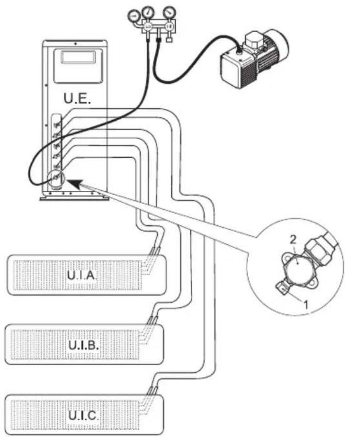
fig. 24 -
2.13 CONNECTION AREA CLOSING
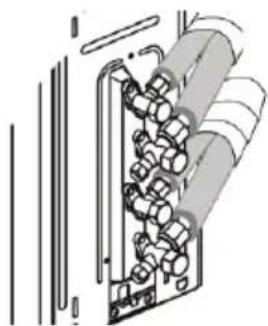
After carrying out all the above-mentioned connections, reposition the cooling connection cover case (part A - "fig. 25 -").
natural_image
Technical line drawing of a dual air conditioner unit with fan and cooling unit (no text or symbols)fig. 25 -
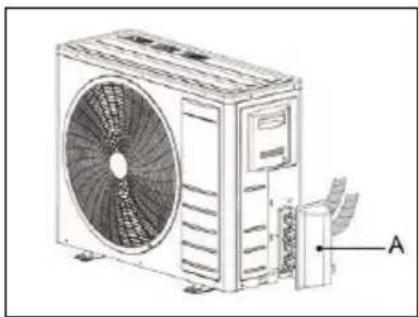
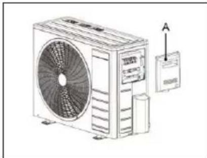
2.14 ELECTRICAL CONNECTION OF THE OUTDOOR UNIT
- Remove the side panel (part A - "fig. 26 -").
- Make the connections referring to the wiring diagrams of the unit.
- Close the machine up again.
natural_image
Line drawing of a large air conditioner unit with fan and control panel, no text or symbols presentfig. 26 -
2.15 ELECTRICAL CONNECTIONS
- The customer must provide a separate power line for the conditioner fitted with an automatic safety device (heavy-duty circuit breaker) upstream the line.
- Make sure that the power line voltage matches that indicated on the rating plate.
- The power line of all the models must be fitted with a suitably sized earth connector.
- The lines powering the fixed loads of the unit (compressor, fans, etc.) have been sized according to current legislation governing overload and short circuit protection.
- The conductors from the power supply running directly to the input terminals of the general switch must be connected (consult the wiring diagrams supplied with the unit).
- The electrical panels are fitted with a terminal for connecting the earth wire, identified by the marking ⏻.
2.16 ELECTRICAL CONNECTIONS
To allow the conditioner to start, make the electrical connections as shown in the wiring diagrams supplied with the unit. The two units must be connected to an efficient earth circuit. The maker declines all liability if this precaution is ignored.
Note: When working on the electrical system, refer to the wiring diagrams supplied with the unit. For connections to the power and control circuits, comply with the specifications shown in the following tables.
| CHARACTERISTICS\MODEL | 18-2 | 18-2 27-3 28-4 | ||||
| Type of Power Supply " 230/1/50 | ||||||
| Circuit breaker IG A 16 16 25 25 | ||||||
| Wire section | A mm2 3x2.5 3x2.5 3x2.5 3x2.5 | |||||
| B mm2 4x1.5 4x1.5 4x1.5 | ||||||
Recommended cable H05RN-F or as installed. See specific legislation. The customer must install the automatic circuit breaker. Mod. 18-2
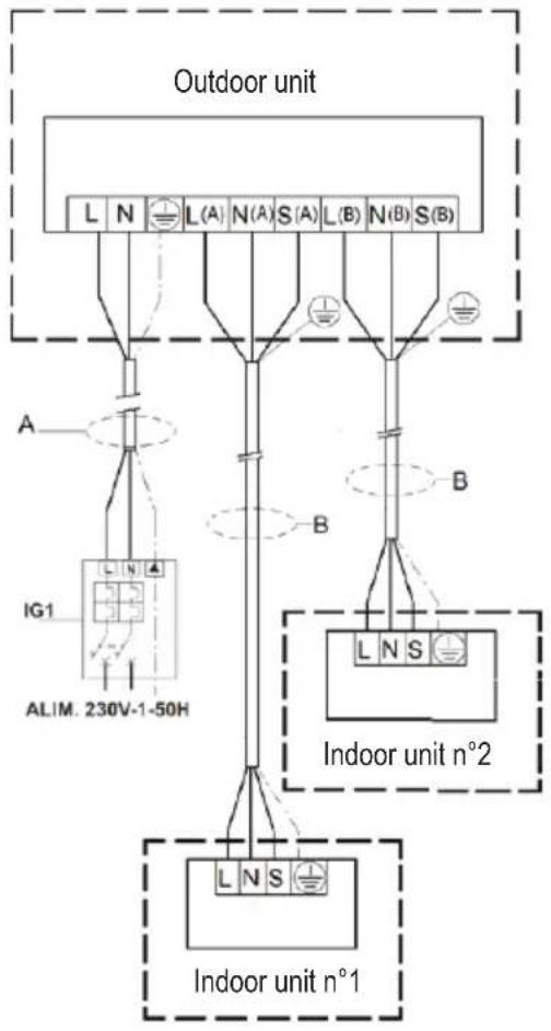
fig. 27 -
Mod. 27-3
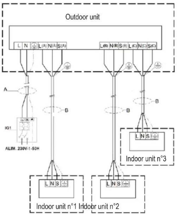
flowchart
graph TD
    subgraph_Outdoor_unit["Outdoor unit"]
        L1["L"] --> N1["N"]
        N1 --> A["A"]
        A --> IG1["IG1"]
        IG1 --> ALIM["ALIM, 230V-1-50H"]
        S1["S(A)"] --> A
        S1 --> B["B"]
        B --> L2["L"]
        L2 --> N2["N"]
        N2 --> B2["B"]
        B2 --> L3["L"]
        L3 --> N3["N"]
        N3 --> S3["S(C)"]
        S3 --> B3["B"]
        B3 --> L4["L"]
        L4 --> N4["N"]
        N4 --> B4["B"]
        B4 --> L5["L"]
        L5 --> N5["N"]
        N5 --> B5["B"]
        B5 --> L6["L"]
        L6 --> N6["N"]
        N6 --> B6["B"]
        B6 --> L7["L"]
        L7 --> N7["N"]
        N7 --> B7["B"]
        B7 --> L8["L"]
        L8 --> N8["N"]
        N8 --> B8["B"]
        B8 --> L9["L"]
        L9 --> N9["N"]
        N9 --> B9["B"]
        B9 --> L10["L"]
        L10 --> N10["N"]
        N10 --> B10["B"]
        B10 --> L11["L"]
        L11 --> N11["N"]
        N11 --> B12["B"]
        B12 --> L13["L"]
        L13 --> N13["N"]
        N13 --> B13["B"]
        B13 --> L14["L"]
        L14 --> N14["N"]
        N14 --> B14["B"]
        B14 --> L15["L"]
        L15 --> N15["N"]
        N15 --> B15["B"]
        B15 --> L16["L"]
        L16 --> N16["N"]
        N16 --> B16["B"]
        B16 --> L17["L"]
        L17 --> N17["N"]
        N17 --> B17["B"]
        B17 --> L18["L"]
        L18 --> N18["N"]
        N18 --> B18["B"]
        B18 --> L19["L"]
        L19 --> N19["N"]
        N19 --> B19["B"]
        B19 --> L20["L"]
        L20 --> N20["N"]
        N20 --> B20["B"]
        B20 --> L21["L"]
        L21 --> N21["N"]
        N21 --> B21["B"]
        B21 --> L22["L"]
        L22 --> N22["N"]
        N22 --> B22["B"]
        B22 --> L23["L"]
        L23 --> N23["N"]
        N23 --> B23["B"]
        B23 --> L24["L"]
        L24 --> N24["N"]
        N24 --> B24["B"]
        B24 --> L25["L"]
        L25 --> N25["N"]
        N25 --> B25["B"]
        B25 --> L26["L"]
        L26 --> N26["N"]
        N26 --> B26["B"]
        B26 --> L27["L"]
        L27 --> N27["N"]
        N27 --> B27["B"]
        B27 --> L28["L"]
        L28 --> N28["N"]
        N28 --> B28["B"]
        B28 --> L29["L"]
        L29 --> N29["N"]
        N29 --> B29["B"]
        B29 --> L30["L"]
        L30 --> N30["N"]
        N30 --> B30["B"]
        B30 --> L31["L"]
        L31 --> N31["N"]
        N31 --> B31["B"]
        B31 --> L32["L"]
        L32 --> N32["N"]
        N32 --> B32["B"]
        B32 --> L33["L"]
        L33 --> N33["N"]
        N33 --> B33["B"]
        B33 --> L34["L"]
        L34 --> N34["N"]
        N34 --> B34["B"]
        B34 --> L35["L"]
        L35 --> N35["N"]
fig. 28 -
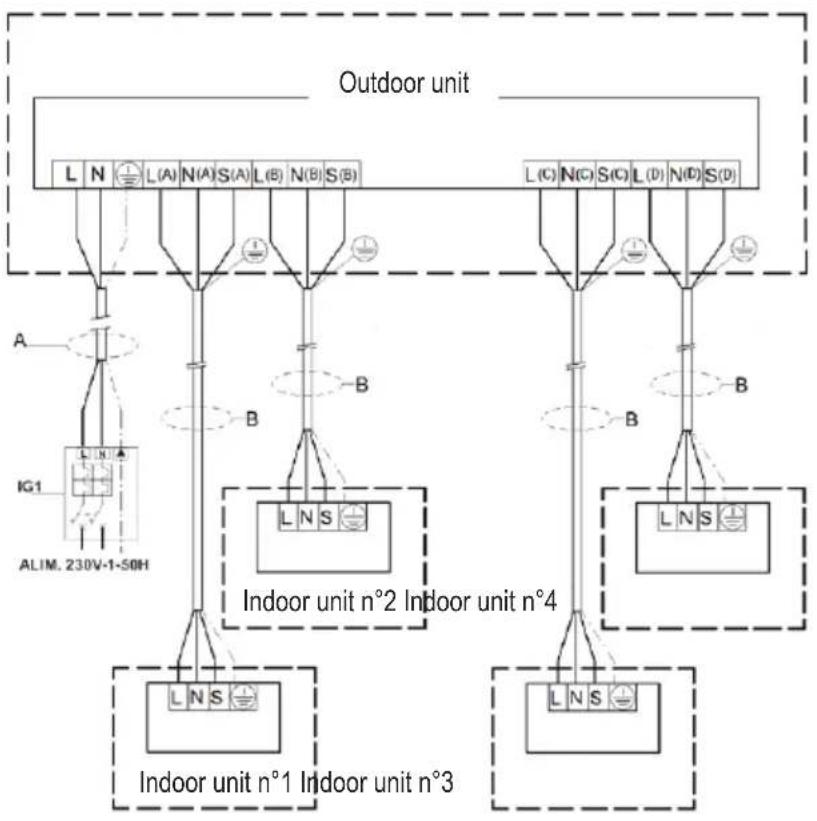
Mod. 28-4
flowchart
graph TD
    subgraph Outdoor unit
        A["Indoor unit n°2 Indoor unit n°4"]
        B["Indoor unit n°1 Indoor unit n°3"]
    end
    subgraph Indoor unit n°2 Indoor unit n°4
        C["Indoor unit n°2 Indoor unit n°4"]
        D["Indoor unit n°1 Indoor unit n°3"]
    end
    E["ALIM. 230V-1-50H"] --> F["A"]
    F --> G["L (A)"]
    F --> H["N (A)"]
    F --> I["S (A)"]
    F --> J["L (B)"]
    F --> K["N (B)"]
    F --> L["S (B)"]
    M["Outdoor unit"] --> N["L (C)"]
    M --> O["N (C)"]
    M --> P["S (C)"]
    M --> Q["L (D)"]
    M --> R["N (D)"]
    M --> S["S (D)"]
    T["Indoor unit n°2 Indoor unit n°4"] --> U["L (N)"]
    T --> V["B"]
    W["Indoor unit n°1 Indoor unit n°3"] --> X["L (N)"]
    W --> Y["B"]
    Z["Indoor unit n°2 Indoor unit n°4"] --> AA["L (N)"]
    Z --> AB["B"]
    AC["Indoor unit n°1 Indoor unit n°3"] --> AD["L (N)"]
    AC --> AE["B"]
fig. 29 -
3. SETTING AND WORK
3.1 STARTING UP FOR THE FIRST TIME
Before starting the unit for the first time, before starting the system for seasonal work or after a long period at a standstill, carry out the following preliminary inspections with regard to the electrical and cooling parts.
3.2 PRELIMINARY CHECKS ON THE ELECTRICAL PART
Note: Before inspecting any electrical part, disconnect the power supply from the machine by unplugging it from the mains socket. Checks
• Make sure that the electrical system has been wired-up according to the indications in the wiring diagram and that the cross section of the cables is adequate.
• Make sure that the power supply and earth cables are firmly connected to the terminals.
• Make sure that there are no disconnected or unhooked cables.
• Make sure that the mains power supply suits the machine requirements.
3.3 PRELIMINARY CHECKS ON THE COOLING PART
- Make sure that the unit is loaded with refrigerant. This may be checked by using portable Freon gauges provided with swivelling SAE 1/4'' connections with air pump connected to the service connection of the tap. The pressure read must correspond to the saturation pressure corresponding to the room temperature ( 7 bar).
- Visually check the cooling circuit to make sure that it is not damaged.
• Make sure that the pipes are not dirty with oil (oil stains could denote possible damage to the cooling circuit).
3.4 STARTING
After performing preliminary controls, start the machine with the remote control. Press the ON button and select the required operating mode.
The remote control functions are illustrated in the user manual.
4. SAFETY AND POLLUTION
4.1 GENERAL CONSIDERATIONS
The machine has been designed to reduce risks to persons and to the environment in which it is installed, to the minimum. To eliminate residual hazards, it is therefore recommended to become as familiar as possible with the
machine in order to avoid accidents that could cause personal injuries and/or damage to the machine.
Pollution
The machine contains lubricating oil and R32 refrigerant. If the unit is scrapped, these fluids must be recovered and disposed of in compliance with the laws in force in the country where the machine is installed. The machine must not be dumped when no longer required for service.
Consult the technical safety briefs available from refrigerant manufacturers for further information about the characteristics of the cooling fluid.
The Refrigerant
To realize the function of the air conditioner unit, a special refrigerant circulates in the system. The used refrigerant is the fluoride R32, which is specially cleaned. The refrigerant is flammable and inodorous. Furthermore, it can leads to explosion under certain condition. But the flammability of the refrigerant is very low. It can be ignited only by fire. Compared to common refrigerants, R32 is a nonpolluting refrigerant with no harm to the ozonosphere. The influence upon the greenhouse effect is also lower. R32 has got very good thermodynamic features which lead to a really high energy efficiency. The units therefore need a less filling.
1. CARACTERÍSTICAS GENERALES....44
natural_image
Technical line drawing of a fan-shaped air conditioning unit (no text or symbols)fig. 1 -
| MOD. 18-2 27-3 28-4 UM | |||
| D 333 363 420 mm | |||
| H 554 702 810 mm | |||
| W 800 845 946 mm | |||
| W1 70 69 84 mm |
fig. 2 -
1.10 NORMAS DE SEGURIDAD
natural_image
Illustration of a refrigerated air conditioner unit with airflow direction indicated (no text or symbols)fig. 3 -
2.2 CONTENIDO
fig. 9 -
natural_image
Line drawing of a dual air conditioner unit with fan and water drop pipe (no text or symbols)fig. 10 -
natural_image
Line drawing of a mechanical device with a cylindrical base and a flanged top (no text or symbols)fig. 12 -

natural_image
Line drawing of a hand holding a small cylindrical object, possibly a tool or device (no text or symbols present)fig. 13 -
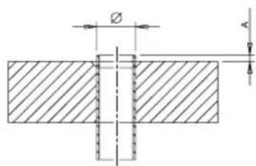
fig. 14 -

fig. 15 -
natural_image
Technical line drawing of a mechanical component with cylindrical shaft and flanged end (no text or symbols)fig. 16 -
Tabella. 1 - "fig. 14 -"
| Diámetro nominal (“) | Diámetro externo (mm) ∅ | Espesor tubo (mm) A (mm) | |
| 1/4 6,35 0,80 | 1,5 ~ 2,0 | ||
| 3/8 9,52 0,80 | 1,5 ~ 2,0 | ||
| 1/2 12,70 0,80 | 2,0 ~ 2,5 | ||
| 5/8 15,88 1,00 | 2,0 ~ 2,5 |
Tabella. 2 - "fig. 17 -"
| Diámetro nominal (“) | Diámetro externo (mm) ∅ | Espesor tubo (mm) | A (mm) | ||||
| A B C D | Grosor de unión (mm) | ||||||
| 1/4 6,35 | 0,80 9,1 9,2 6,5 13 17 | ||||||
| 3/8 9,52 | 0,80 13,2 13,5 9,7 20 | 22 | |||||
| 1/2 | 12,70 | 0,80 | 16,6 | 16,0 | 12,9 | 23 | 26 |
| 5/8 | 15,88 | 1,00 | 19,7 | 19,0 | 16,0 | 25 | 29 |

fig. 17 -
natural_image
Technical line drawing of a mechanical connector assembly (no text or symbols)fig. 18 -
2.8 CONEXIONES FRIGORÍFICAS
fig. 19 -
fig. 20 -

fig. 21 -
2.9 AISLAMIENTO DE LOS TUBOS
natural_image
Diagram of a mechanical assembly with gears and shafts, no text or symbols presentfig. 22 -
2.10 APRIETE DE LOS TUBOS
natural_image
Line drawing of a dual air conditioner unit with fan and cooling unit (no text or symbols)fig. 25 -
natural_image
Line drawing of a large air conditioner unit with fan and control panel (no text or symbols)fig. 26 -
2.15 CARACTERÍSTICAS ELÉCTRICAS GENERALES
natural_image
Technical line drawing of a fan-shaped air conditioning unit (no text or symbols)fig. 1 -
| MOD. 18-2 27-3 28-4 UM | |||
| D 333 363 420 mm | |||
| H 554 702 810 mm | |||
| W 800 845 946 mm | |||
| W1 70 69 84 mm |
1.7 TABEL COMBINATII
fig. 2 -
1.10 NORME DE SIGURANTĂ
natural_image
Isometric line drawing of a refrigerated air conditioner unit with upward arrow indicating airflow or heat transfer (no text or symbols)fig. 3 -
2.2 CONTINUT
fig. 9 -
natural_image
Line drawing of a dual air conditioner unit with fan and water drop (no text or symbols)fig. 10 -
2.7 CONDUCTE DE CONEXIUNE
natural_image
Line drawing of a mechanical device with a cylindrical base and a vertical rod, no text or symbols present.fig. 12 -
natural_image
Line drawing of a hand holding a small cylindrical object, possibly a tool or device (no text or symbols present)fig. 13 -

fig. 14 -

fig. 15 -
natural_image
Technical line drawing of a cylindrical mechanical component with a flanged end (no text or symbols)fig. 16 -
Tabella. 1 - "fig. 14 -"
| Diametru nominal (") | Diametru exterior (mm) ∅ | Grosimea tubului (mm) A (mm) |
| 1/4 6,35 0,80 | 1,5 ~ 2,0 | |
| 3/8 9,52 0,80 | 1,5 ~ 2,0 | |
| 1/2 12,70 0,80 | 2,0 ~ 2,5 | |
| 5/8 15,88 1,00 | 2,0 ~ 2,5 |
Tabella. 2 - "fig. 17 -"
| Diametru nominal (") | Diametru exterior (mm) ∅ | Grosimea tubului (mm) | A (mm) | ||||
| A B C D | Grosimea unirii conductelor (mm) | ||||||
| 1/4 6,35 | 0,80 9,1 9,2 | 6,5 13 17 | |||||
| 3/8 9,52 | 0,80 13,2 13,5 | 9,7 20 22 | |||||
| 1/2 | 12,70 | 0,80 16,6 | 16,0 12,9 | 23 26 | |||
| 5/8 | 15,88 | 1,00 19,7 | 19,0 16,0 | 25 29 | |||
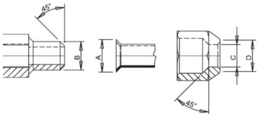
fig. 17 -
natural_image
Technical line drawing of a mechanical connector assembly (no text or symbols)fig. 18 -
2.8 CONEXIUNI DE REFRIGERARE
fig. 19 -
fig. 20 -

fig. 21 -
2.9 IZOLAREA CONDUCTELOR
natural_image
Diagram of a mechanical device with gears and shafts, no text or symbols presentfig. 22 -
2.10 STRÂNGEREA CONDUCTELOR
natural_image
Line drawing of a large air conditioner unit with fan and cooling unit (no text or symbols)fig. 25 -
2.14 CONEXIUNE ELECTRICĂ UNITATE EXTERNĂ
natural_image
Line drawing of a large air conditioner unit with fan blades and control panel (no text or symbols)fig. 26 -
2.15 CONEXIUNI ELECTRICE
natural_image
Technical line drawing of a fan-shaped air conditioning unit (no text or symbols)réf. 1 -
| MOD. 18-2 27-3 28-4 UM | |||
| D 333 363 420 mm | |||
| H 554 702 810 mm | |||
| W 800 845 946 mm | |||
| W1 70 69 84 mm |
1.7 TABLEAU DES COMBINAISONS
1.8 CHAMP D'APPLICATION
réf. 2 -
1.10 RÈGLES DE SÉCURITÉ
natural_image
Illustration of a refrigerated air conditioner unit with airflow direction indicated (no text or symbols)réf. 3 -
2.2 CONTENU
réf. 9 -
natural_image
Line drawing of a wall-mounted air conditioner unit with fan and water drop (no text or symbols)réf. 10 -
2.7 TUYAUX DE RACCORDEMENT
réf. 11 -
natural_image
Line drawing of a mechanical device with a cylindrical base and a vertical rod, no text or symbols present.réf. 12 -
natural_image
Line drawing of a hand holding a small cylindrical object with a pointed tip (no text or symbols)réf. 13 -
réf. 14 -

réf. 15 -

natural_image
Technical line drawing of a mechanical component with cylindrical and ring features (no text or symbols)natural_image
Technical line drawing of a mechanical connector assembly (no text or symbols)réf. 18 -
2.8 RACCORDEMENTS FRIGORIFIQUES
réf. 19 -
réf. 20 -

réf. 21 -
2.9 CALORIFUGEAGE DES TUYAUTERIES
natural_image
Diagram of a mechanical device with gears and shafts, no text or symbols presentréf. 22 -
2.10 SERRAGE DES TUYAUX
natural_image
Illustration of a dual air conditioner unit with fan and cooling tower (no text or symbols)réf. 25 -
2.14 CONNEXIONS ÉLECTRIQUES DE L'UNITÉ EXTÉRIEURE
natural_image
Line drawing of a large air conditioner unit with fan blades and control panel, no text or symbols presentréf. 26 -
2.15 CARACTÉRISTIQUES ÉLECTRIQUES GÉNÉRALES
natural_image
Technical line drawing of a fan-shaped industrial air conditioning unit (no text or symbols)rys. 1 -
| MOD. 18-2 27-3 28-4 UM | |||
| D 333 363 420 mm | |||
| H 554 702 810 mm | |||
| W 800 845 946 mm | |||
| W1 70 69 84 mm |
1.7 TABELA POŁĄCZEŃ
rys. 2 -
1.10 ZASADY BEZPIECZEŃSTWA
natural_image
Isometric line drawing of a refrigerated air conditioner unit with upward arrow indicating airflow or heat transfer (no text or symbols)rys. 3 -
2.2 ZAWARTOŚĆ
rys. 9 -
natural_image
Line drawing of a dual air conditioner unit with fan and water drop (no text or symbols)rys. 10 -
2.7 RURY ŁACZACE
natural_image
Line drawing of a mechanical device with a cylindrical base and a vertical rod, no text or symbols present.rys. 12 -

natural_image
Line drawing of a hand holding a small cylindrical object, possibly a tool or device (no text or symbols present)rys. 13 -
rys. 14 -
rys. 15 -

natural_image
Technical line drawing of a cylindrical mechanical component with a flanged end (no text or symbols)rys. 16 -
Tabella. 1 -
| Średnica nominalna ('') | Średnica zewnętrzna (mm) | Grubo rury (mm) A (mm) | |
| 1/4 6,35 0,80 | 1,5 ~ 2,0 | ||
| 3/8 9,52 0,80 | 1,5 ~ 2,0 | ||
| 1/2 12,70 0,80 | 2,0 ~ 2,5 | ||
| 5/8 15,88 1,00 | 2,0 ~ 2,5 |
Tabella. 2 -
| Średnica nominalna (") | Średnica zewnętrzna (mm) ∅ | Grubo rury (mm) | A (mm) | ||||
| A B C D | Grubo złączki (mm) | ||||||
| 1/4 6,35 | 0,80 9,1 9,2 | 6,5 13 17 | |||||
| 3/8 9,52 | 0,80 13,2 | 13,5 | 9,7 20 | 22 | |||
| 1/2 | 12,70 | 0,80 | 16,6 | 16,0 | 12,9 | 23 | 26 |
| 5/8 | 15,88 | 1,00 | 19,7 | 19,0 | 16,0 | 25 | 29 |

rys. 17 -
natural_image
Technical line drawing of a mechanical connector assembly (no text or symbols)rys. 18 -
2.8 PODŁĄCZENIA OBWODU CHŁODZENIA
rys. 19 -
rys. 20 -

rys. 21 -
natural_image
Diagram of a mechanical device with rotating components and internal gears (no text or symbols)rys. 22 -
2.10 DOKREÇENIE RUR
natural_image
Technical line drawing of a dual air conditioner unit with fan and cooling unit (no text or symbols)rys. 25 -
natural_image
Line drawing of a large air conditioner unit with fan and control panel (no text or symbols)rys. 26 -
natural_image
Technical line drawing of a fan-shaped air conditioning unit (no text or symbols)fig. 1 -
| MOD. 18-2 27-3 28-4 UM | |||
| D 333 363 420 mm | |||
| H 554 702 810 mm | |||
| W 800 845 946 mm | |||
| W1 70 69 84 mm |
1.7 TABELA DE COMBINAÇÕES
fig. 2 -
1.10 NORMAS DE SEGURANÇA
natural_image
Diagram of a refrigerated air conditioner unit with airflow direction indicated (no text or symbols)fig. 3 -
2.2 CONTEÚDOS
fig. 9 -
natural_image
Line drawing of a dual air conditioner unit with fan and water drop (no text or symbols)fig. 10 -
natural_image
Line drawing of a large air conditioner unit with fan and cooling unit (no text or symbols)fig. 25 -
natural_image
Line drawing of a large air conditioner unit with fan blades and control panel, no text or symbols presentfig. 26 -
2.15 CARACTERÍSTICAS ELÉTRICAS GERAIS


- CE
- CARATTERISTICHE GENERALI 3
- INSTALLAZIONE 8
- MESSA IN FUNZIONE....21
- SICUREZZA ED INQUINAMENTO....21
- TABELLA ABBINAMENTI
- NORME DI SICUREZZA
- CONTENUTO
- COLLEGAMENTI FRIGORIFERI
- COLLEGAMENTO ELETTRICO UNITA' ESTERNA
- COLLEGAMENTI ELETTRICI GENERALITA'
- SETTING AND WORK....42
- SAFETY AND POLLUTION 42
- GENERAL SPECIFICATIONS
- CONSIGNMENT OF THE MACHINE
- FOREWORD
- PRESENTATION OF THE UNIT
- Appliance filled with flammable gas R32.
- DECLARATION OF CONFORMITY
- OVERALL DIMENSIONS
- MATCHING TABLE
- APPLICATION FIELD
- UNITDESCRIPTION
- CABINET FOR THE OUTDOOR UNIT
- 2.COMPRESSOR
- VENTILATING UNIT
- HEAT EXCHANGE BANK
- COOLING CIRCUIT
- SAFETY REGULATIONS
- INSTALLATION
- PACKING AND STORING
- CONTENT
- GENERAL NOTES
- LIMITS TO THE LENGTH AND HEIGHT DIFFERENCE OF REFRIGERANT PIPES
- INSTALLING THE OUTDOOR UNIT
- CONDENSATION DRAIN KIT FOR OUTDOOR UNIT
- CONNECTION PIPES
- COOLING CONNECTIONS
- PIPE INSULATION
- PIPE CLAMPING
- TIGHTNESS CHECK (RECOMMENDED OPERATION)
- CONNECTION AREA CLOSING
- ELECTRICAL CONNECTION OF THE OUTDOOR UNIT
- ELECTRICAL CONNECTIONS
- ELECTRICAL CONNECTIONS
- SETTING AND WORK
- STARTING UP FOR THE FIRST TIME
- PRELIMINARY CHECKS ON THE ELECTRICAL PART
- PRELIMINARY CHECKS ON THE COOLING PART
- STARTING
- SAFETY AND POLLUTION
- GENERAL CONSIDERATIONS
- Pollution
- The Refrigerant
- CARACTERÍSTICAS GENERALES....44
- NORMAS DE SEGURIDAD
- CONTENIDO
- CONEXIONES FRIGORÍFICAS
- AISLAMIENTO DE LOS TUBOS
- APRIETE DE LOS TUBOS
- CARACTERÍSTICAS ELÉCTRICAS GENERALES
- TABEL COMBINATII
- NORME DE SIGURANTĂ
- CONTINUT
- CONDUCTE DE CONEXIUNE
- CONEXIUNI DE REFRIGERARE
- IZOLAREA CONDUCTELOR
- STRÂNGEREA CONDUCTELOR
- CONEXIUNE ELECTRICĂ UNITATE EXTERNĂ
- CONEXIUNI ELECTRICE
- TABLEAU DES COMBINAISONS
- CHAMP D'APPLICATION
- RÈGLES DE SÉCURITÉ
- CONTENU
- TUYAUX DE RACCORDEMENT
- RACCORDEMENTS FRIGORIFIQUES
- CALORIFUGEAGE DES TUYAUTERIES
- SERRAGE DES TUYAUX
- CONNEXIONS ÉLECTRIQUES DE L'UNITÉ EXTÉRIEURE
- CARACTÉRISTIQUES ÉLECTRIQUES GÉNÉRALES
- TABELA POŁĄCZEŃ
- ZASADY BEZPIECZEŃSTWA
- ZAWARTOŚĆ
- RURY ŁACZACE
- PODŁĄCZENIA OBWODU CHŁODZENIA
- DOKREÇENIE RUR
- TABELA DE COMBINAÇÕES
- NORMAS DE SEGURANÇA
- CONTEÚDOS
- CARACTERÍSTICAS ELÉTRICAS GERAIS
Brand : FERROLI
Model : Diamant Plus M
Category : Air Conditioning