
RMA2 He - Air Conditioning FERROLI - Free user manual and instructions
Find the device manual for free RMA2 He FERROLI in PDF.


| Product Type | Split Air Conditioner (Inverter) |
| Cooling Capacity (kW) | 2.5 |
| Heating Capacity (kW) | 3.2 |
| Energy Efficiency Ratio (EER) | 3.5 |
| Power Supply | 220-240 V ~ 50 Hz |
| Refrigerant | R32 |
| Indoor Unit Dimensions (W x H x D) | 780 x 250 x 200 mm |
| Outdoor Unit Dimensions (W x H x D) | 750 x 550 x 300 mm |
| Indoor Unit Weight | 8.5 kg |
| Outdoor Unit Weight | 26 kg |
| Functions | Cool, Heat, Fan, Dehumidify, Timer, Sleep Mode, Turbo Mode |
| Remote Control | Infrared with backlit LCD |
| Air Flow (Max) | 600 m³/h |
| Noise Level Indoor (Low/High) | 24 / 38 dB(A) |
| Noise Level Outdoor | 52 dB(A) |
| Filter Type | Washable, Antibacterial |
| Cleaning | Clean filters every 2-4 weeks; coil annually |
| Safety Features | Overload protection, anti-freeze, auto restart |
| Spare Parts Available | Remote control, filters, fan motor, PCB |
| Repairability Index | 7.5 / 10 |
Frequently Asked Questions - RMA2 He FERROLI
User questions about RMA2 He FERROLI
0 question about this device. Answer the ones you know or ask your own.
Ask a new question about this device
Download the instructions for your Air Conditioning in PDF format for free! Find your manual RMA2 He - FERROLI and take your electronic device back in hand. On this page are published all the documents necessary for the use of your device. RMA2 He by FERROLI.
USER MANUAL RMA2 He FERROLI
natural_image
Technical line drawing of a rectangular industrial fan or fan unit with mounting holes and a central fan blade (no text or symbols)


CE
INSTALLATION AND OPERATION MANUAL
Dear Customer,
Thank you for having purchased a FERROLI product. It is the result of many years of experiences and of particular research studies and has been made with top quality materials and advanced technologies. The CE mark guarantees that the products satisfy all the applicable European Directives.
The qualitative level is kept under constant control and FERROLI products therefore offer SAFETY, QUALITY and RELIABILITY. Due to the continuous improvements in technologies and materials, the product specification as well as performances are subject to variations without prior notice.
Thank you once again for your
FERROLI S.p.A
The manufacturer declines all the responsibilities regarding inaccuracies contained in this manual, if due to printing or typing mistakes. The manufacturer reserves the right to apply changes and improvements to the products at any time without notice.
TABLE OF CONTENTS
GENERAL FEATURES 4
General specifications 4
Declaration of conformity 4
Unit dataplate....4
Unit description 5
Unit identification code....5
Description of components....6
Control system 7
Versions....7
ACCESSORIES AND OPTIONAL EQUIPMENT....8
Options....8
Accessories 9
TECHNICAL DATA AND PERFORMANCE - BASE VERSION (VB) 10
Technical data 10
NET NOMINAL performances - Base setting up (AB) - Standard plants - EUROVENT certified data ..... 11
NET NOMINAL performances - Base setting up (AB) - Radiant plants 11
NET NOMINAL performances - Low noise setting up (AS) - Standard plants - EUROVENT certified data . . . . . . . . . . . . . . . . . . . . . . . . . 12
NET NOMINAL performances - Low noise setting up (AS) - Radiant plants 12
COOLING performances....13
HEATING performances 14
BR-BP UNIT....15
Corrective factors....15
NOISE LEVELS....16
ELECTRICAL DATA 17
Electrical data. 17
OPERATING LIMITS....18
WATER PRESSURE DROP 19
WORKING HEAD. 20
DIMENSIONAL AND PHYSICAL DATA 22
Overall dimensions....22
Minimum operating area 22
Weights 23
RECEPTION AND POSITIONING....24
Receiving 24
Positioning 24
HYDRAULIC CONNECTIONS....25
General rules 25
Protection devices 25
Tips for a successful installation 25
Water component for corrosion limit 26
Precautions for the Winter 26
Air vent and water drain 26
Maximum volume of water in the system with wet module 26
ELECTRICAL CONNECTIONS....27
Electrical connections 27
R410A PROTECTION DEVICES....28
REFRIGERANT FLOW DIAGRAM 29
IR unit....29
IP unit....29
CONTROL SYSTEM 30
Control system....30
Menu structure....32
Inputs and outputs 33
Controller technical data 33
Alarms 34
Alarms table 35
Functions available for the user....36
Serial communication....37
Probes characteristics 38
INVERTER....39
Operating setting procedure....39
Alarm 39
START UP 42
Start up....42
Preliminary operation....42
SAFETY AND MAINTENANCE....43
Basic safety rules....43
General recommendations about the R410A refrigerant used. 44
General Rules for Maintenance 46
Routine maintenance....46
GENERAL FEATURES
CONTAINS FLUORINATED GREENHOUSE GASES COVERED BY THE KYOTO PROTOCOL:
- R410A (GLOBAL WARMING POTENTIAL GWP = 2088)
General specifications
- This manual and the wiring diagram supplied with the unit must be kept in a dry place and ready to hand for future consultation when required.
- This manual has been compiled to ensure that the unit is installed in the correct way and to supply comprehensive information about how to correctly use and service the appliance. Before proceeding with the installation phase, please carefully read all the information in this manual, which describes the procedures required to correctly install and use the unit.
- Strictly comply with the instructions in this manual and conform to the current safety standards.
- The appliance must be installed in accordance with the laws in force in the country in which the unit is installed.
- Unauthorized tampering with the electrical and mechanical equipment will VOID THE WARRANTY.
- Check the electrical specifications on the identification plate before making the electrical connections. Read the instructions in the specific section where the electrical connections are described.
- If the unit must be repaired for any reason, this must only be done by a specialized assistance center recognized by the manufacturer and using genuine spare parts.
- The manufacturer also declines all liability for any damage to persons or property deriving from failure of the information in this manual to correspond to the actual machine in your possession.
- Proper uses: this series of chillers is designed to produce cold or hot water for use in hydronic systems for conditioning/heating purposes. The units are not suitable for the production of domestic hot water.
Any use differing from this proper use or beyond the operating limits indicated in this manual is forbidden unless previously agreed with the manufacturer. - The prevention of the risk of fire at the installation site is the responsibility of the end user.
Declaration of conformity
The company hereby declares that the machine in question complies with the matters prescribed by the following Directives:
- Machine
Directive
2006/42/CE
• Directive governing pressurized vessels (PED) 97/23/CE
• Electromagnetic compatibility Directive (EMC) 2004/108/CE
• Low voltage Directive (LVD) 2006/95/CE
Unit dataplate
The figure shows the fields reported on the unit dataplate :
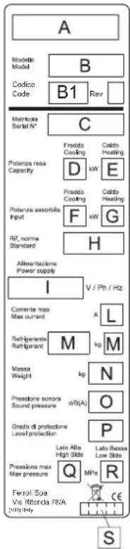
A - Trademark
B - Model
B1 - Code
C - Serial number
D - Capacity in cooling
E - Capacity in heating (heat pump)
F - Power input in cooling
G - Power input in heating (heat pump)
H - Reference standard
I - Power supply
L - Maximum absorbed current
M - Refrigerant type and charge weight
N - Weight empty unit
O - Sound pressure level at 1 metre
P - IP protection level
Q - Maximum pressure - high pressure side
R - Maximum pressure - low pressure side
S - PED certification body
GENERAL FEATURES
Unit description
This series of air-water chillers and heat pumps satisfies the cooling and heating requirements of residential plants of small and medium size.
All the units are suitable for outdoor installation and can be applied to fan coil plants, radiant floor plants and high efficiency radiators plants.
The refrigerant circuit, contained in a compartment protected from the air flow to simplify the maintenance operations, is equipped with scroll compressor mounted on damper supports, brazed plate heat exchanger, thermostatic expansion valve, reverse cycle valve, axial fans with safety protection grilles, finned coil made of copper pipes and aluminium louvered fins. The circuit is protected by high and low pressure switches and differential pressure switch on the plate heat exchanger.
The plate heat exchanger and all the hydraulic pipes are thermally insulated in order to avoid condensate generation and to reduce thermal losses.
All the units can be equipped with variable speed fans control
that allows the units to operate with low outdoor temperatures in cooling and high outdoor temperature in heating and permits to reduce noise emissions in such operating conditions.
The low noise acoustic setting up (AS) is obtained, starting from the base setting up (AB), reducing the rotational speed of the fans and mounting sound jackets on the compressors.
All the units are supplied with an outdoor temperature sensor, already installed on the unit, in order to realize the climatic control. All the units are provided with a phase presence and correct sequence controller device.
All the units are accurately built and individually tested in the factory. Only electric and hydraulic connections are required for installation.
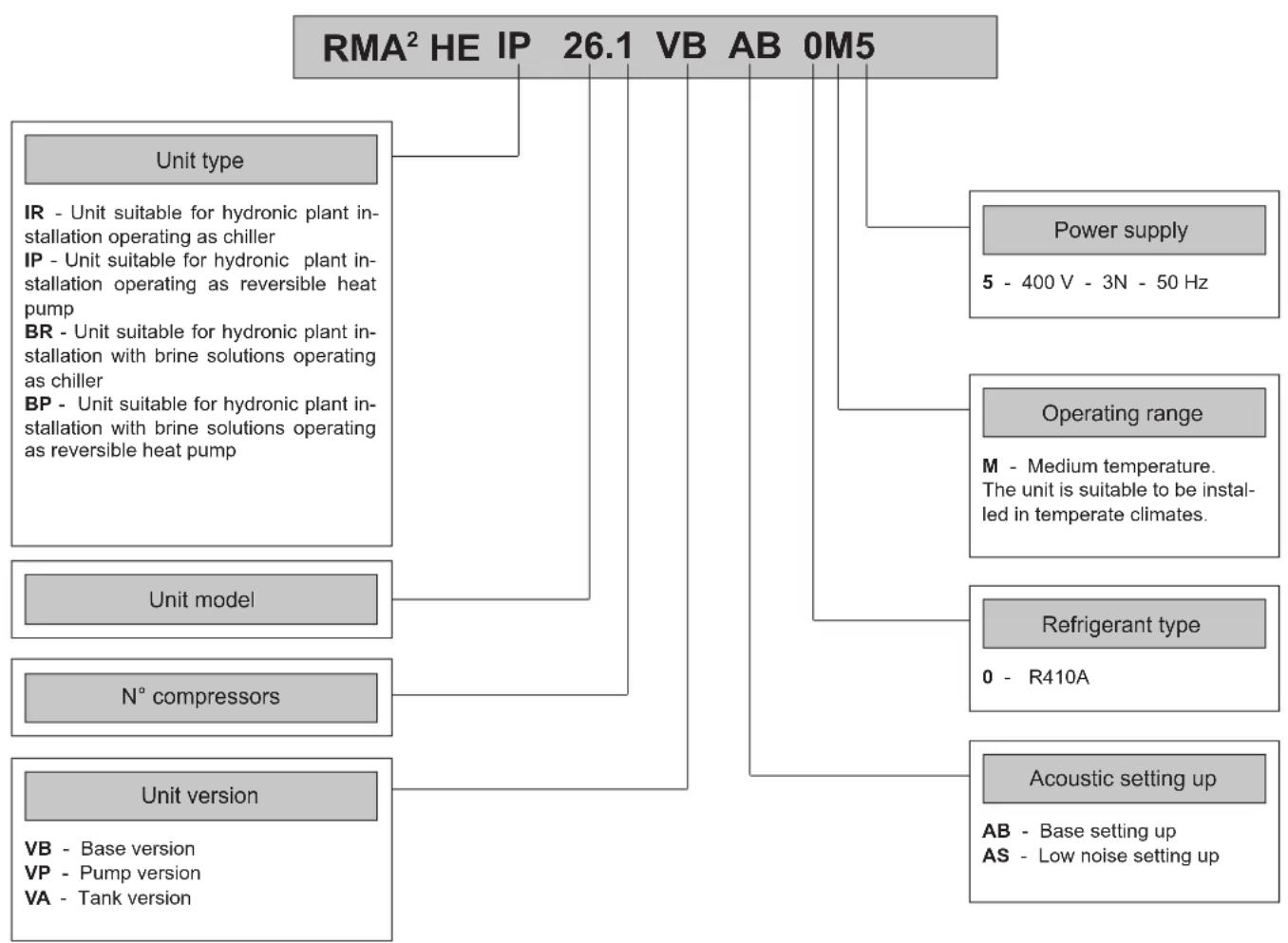
Unit identification code
The codes that identify the units and the meaning of the letters used are described below.
flowchart
graph TD
    A["RMA² HE IP 26.1 VB AB 0M5"] --> B["Unit type"]
    A --> C["Power supply\n5 - 400 V - 3N - 50 Hz"]
    A --> D["Operating range\nM - Medium temperature.\nThe unit is suitable to be instal-led in temperate climates."]
    A --> E["Refrigerant type\n0 - R410A"]
    A --> F["Acoustic setting up\nAB - Base setting up\nAS - Low noise setting up"]
    B --> G["IR - Unit suitable for hydronic plant in-stallation operating as chiller"]
    B --> H["IP - Unit suitable for hydronic plant in-stallation operating as reversible heat pump"]
    B --> I["BR - Unit suitable for hydronic plant in-stallation with brine solutions operating as chiller"]
    B --> J["BP - Unit suitable for hydronic plant in-stallation with brine solutions operating as reversible heat pump"]
    C --> K["Unit model"]
    D --> L["N° compressors"]
    E --> M["Unit version"]
    F --> N["VB - Base version\nVP - Pump version\nVA - Tank version"]
Description of components
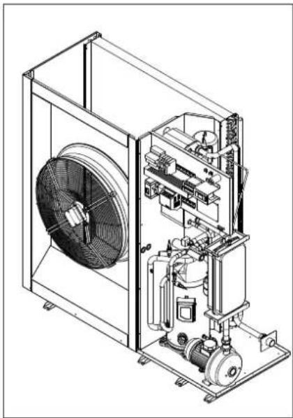
External structure. Basement, supporting structure and lateral panels are made of galvanized and painted sheet-steel (colour RAL 7035) to guarantee good resistance to atmospheric agents. Accessibility to internal parts is possible removing the frontal panel. For extraordinary manteinances also the rear panel can be removed.

natural_image
Technical line drawing of an open industrial fan or compressor unit with internal components (no text or symbols)Refrigerant circuit. It is contained inside a compartment separated from the air flow to simplify maintenance and control operations.
The hermetic scroll compressor (1) is mounted on damper supports and is protected against overtemperatures and overcurrents. It is equipped with an electrical heater, that is activated when the compressor turns off, to keep the compressor crankcase oil temperature high enough to prevent migration of the refrigerant during winter stops and to evaporate any liquid present in the crankcase, in order to prevent possible liquid rushes on starting (only heat pump units, accessory for cooling only units).
The plant side heat exchanger (2) is a brazed stainless steel plate heat exchanger, properly insulated to avoid condensate generation and to minimize thermal losses, and protected by a differential pressure switch that detects whatever water flow lack. It is moreover protected against freeze danger by an antifreeze electrical heater.
The source side heat exchanger (3) is a finned coil realized with grooved copper pipes and aluminium fins with notched profile to increase the heat exchange coefficient. A tray is obtained in the basement to collect the condensate generated in heating mode.
The expansion device (4), a thermostatic expansion valve with external equalizer, allows the unit to adjust itself to the different operating conditions keeping steady the set superheating.
The refrigerant circuit of each unit contains moreover solid core hermetic filter dryer (5) to restrain impurity and moisture
residuals that could be present in the circuit, high and low pressure switches in order to assure the compressor to operate inside the permitted limits, 4 way reverse cycle valve (6) to allow operating mode change reversing the refrigerant flow (only heat pump models), liquid receiver (7) to compensate the different refrigerant charge required in heating and in cooling mode (only heat pump models) and pressure connections SAE 5/16" - UNF 1/2" - 20 equipped with pin, gasket and blind nut, as required for the use of R410A refrigerant (they allow the complete check of the refrigerant circuit: compressor inlet pressure, compressor outlet pressure and thermostatic expansion valve upstream pressure).
The axial fans (8) are contained in a sheet nozzle and are equipped with a safety grille. The fans rotational speed can be modulated continuously by an inverter (option) to control the condensation pressure (in cooling) and the evaporation pressure (in heating) in order to extend the operating limits of the unit and to reduce noise emissions.
Hydraulic circuit. All the pipes are thermally insulated to avoid condensate generation and minimize thermal losses. The circuit can be equipped with different kind of circulation pump (option). In that case the circuit is also equipped with expansion vessel and air vents. It is also possible to integrate inside the unit a buffer tank arranged as buffer on the flow towards the plant (option). In that case the circuit is equipped not only with expansion vessel and air vents, but also with safety valve, automatic air vent and drain cock.
Electrical panel. It contains all the power, control and security components necessary to guarantee the unit to work properly. The unit is managed by a microprocessor controller to which all the electrical loads and the control devices are connected. The user interface, placed on the frontal panel, allows to view and to modify, if necessary, all the parameters of the unit.
All the units are supplied with an outdoor temperature sensor, already installed on the unit, in order to realize the climatic control.

GENERAL FEATURES
Control system
The unit is managed by a microprocessor controller to which, through a wiring board, all the electrical loads and the control devices are connected. The user interface is realized by a display and four buttons that allow to view and, if necessary, modify all the operating parameters of the unit. It's available, as an accessory, a remote control that reports all the functionalities of the user interface placed on the unit.
The main functions available are :
- water temperature management (through set point adjustment)
- adaptive function
- climatic control in heating and in cooling mode (automatic set point adjustment according to outdoor air temperature)
- dynamic defrost cycle management according to outdoor air temperature
- alarm memory management and diagnostic
-
fans management by means of continuous rotational speed control
-
pump management
- integrative electrical heaters management in heating mode (2 step logic)
- compressor and pump operating hours recording
- serial communication through Modbus protocol
- remote stand by
- remote cooling-heating
- general alarm digital output

Versions
Each model can be supplied in three different versions to satisfy the application requirements of the plants. The unit is always supplied assembled, wired and factory tested.
The version is automatically identified by the option "Storing and pumping module" selected.

natural_image
Technical line drawing of an industrial fan assembly with internal components (no text or labels)Base Version - VB
natural_image
Technical line drawing of an industrial fan assembly with internal components (no text or labels)Pump Version - VP

natural_image
Technical line drawing of an industrial fan assembly with visible internal components (no text or labels)Tank Version - VA
The unit does not contain neither circulating pump nor tank. Therefore a proper water flow through the plate heat exchanger must be guaranteed to prevent internal safety devices activation. In any case the pump, if properly sized, can be connected to the electrical panel of the unit and managed by the controller of the unit.
The unit contains a circulating pump, air vents, expansion vessel and drain cock.
The unit contains a tank (arranged as buffer on the flow towards the plant), safety valve, circulating pump, air vents, expansion vessel and drain cock.
The tank is also arranged for the installation of antifreeze or integrative electrical heaters.
ACCESSORIES AND OPTIONAL EQUIPMENT
Options
| Storing and pumping module | Standard pump Allows the circulation of the water on the plant side. | |
| High head pump | Allows the circulation of the water on the plant side and guarantees a higher available static head, suitable for high pressure drop plants. | |
| Modulating pump | Allows the circulation of the water on the plant side with the possibility to set the rotational speed of the pump in order to get the requested flow rate without the necessity to install other setting devices. | |
| Tank and standard pump | Allows the circulation of the water on the plant side.The thermal inertia of the buffer tank allows to reduce the number of compressor starts and to guarantee a more stable flow temperature. | |
| Tank and high head pump | Allows the circulation of the water on the plant side and guarantees a higher available static head, suitable for high pressure drop plants.The thermal inertia of the buffer tank allows to reduce the number of compressor starts and to guarantee a more stable flow temperature. | |
| Tank and modulating pump | Allows the circulation of the water on the plant side with the possibility to set the rotational speed of the pump in order to get the requested flow rate without the necessity to install other setting devices.The thermal inertia of the buffer tank allows to reduce the number of compressor starts and to guarantee a more stable flow temperature. | |
| Electrical heaters | Antifreeze | Activated together with the antifreeze electrical heater of the plate heat exchanger, it has the task to keep the water in the buffer tank at a temperature high enough to avoid ice generation during winter. |
| Integrative | Integrate or replace the heating power supplied by the heat pump and are managed by the unit controller with a 2 step logic.They are also activated as antifreeze electrical heaters.Available only for the VA version. | |
| Soft starter Reduces the compressor start current. | ||
| Compressor power factor correction | Allows to reduce the phase shift between the absorbed current and the power supply voltage keeping it above the value of 0,9. | |
| Fans control | Modulating control (condensation/evaporation control) | The fans rotational speed can be modulated continuously by an inverter to control the condensation pressure (in cooling) and the evaporation pressure (in heating) in order to extend the operating limits of the unit and to reduce noise emissions. |
| Electrical loads protection | Fuses Allows to protect the electrical loads with fuses. | |
| Thermal magnetic circuit breakers | Allows to protect the electrical loads with thermal magnetic circuit breakers simplifying the maintenance operations. | |
Hydraulic scheme
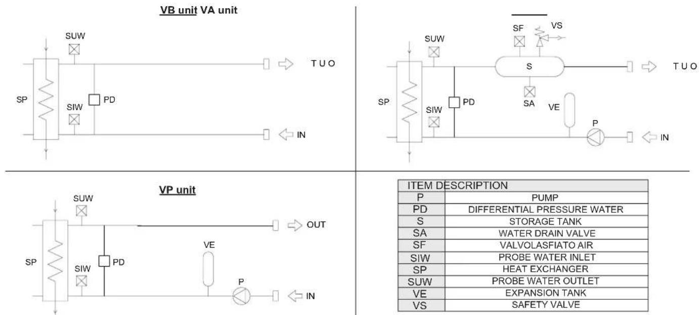
| ITEM DESCRIPTION | |
| P | PUMP |
| PD | DIFFERENTIAL PRESSURE WATER |
| S | STORAGE TANK |
| SA | WATER DRAIN VALVE |
| SF | VALVOLASFIATO AIR |
| SIW | PROBE WATER INLET |
| SP | HEAT EXCHANGER |
| SUW | PROBE WATER OUTLET |
| VE | EXPANSION TANK |
| VS | SAFETY VALVE |
ACCESSORIES AND OPTIONAL EQUIPMENT
Accessories
Supplied accessories
| Rubber vibration dampers | Allow to reduce the transmission to the unit support plane of the mechanical vibrations generated by the compressor and by the fans in their normal operating mode. |
| Coil protection grille Protects | the external surface of the finned coil.. |
| Remote control | It is suitable for wall mounting and reports all the control and visualization functions available on the user interface placed on the unit. It therefore allows the complete remote control of the unit. |
| Modbus serial interface on RS485 | It allows to communicate with the unit controller and to view the operating conditions of the unit through Modbus communication protocol. The RS485 serial line ensures the signal quality up to distances of about 1200 meters (that can be extended by means of proper repeaters). |
| Programmer clock | It allows the unit to be turned on and off according to a set program, through the digital input available on the unit wiring board (remote stand by). |
| Phase sequence and voltage controller | It checks not only the presence and correct order of the power supply phases but also the voltage level on each phase and avoid the unit to operate with voltage levels outside the permitted limits. |
| Water flow switch | Allows to detect the water flow lack through the plate heat exchanger and operates as an integration of the protection offered by the differential pressure switch (standard). |
Factory mounted accessories
| Coil protection grille Protects | the external surface of the finned coil.. |
| Coils protection kit (for transport) | It is a sheet of polystyrene which increases protection of the finned coil during transport. |
| Casing Kits protection (for transport) | Consisting of 4 profiles cardboard that increase the protection of the casing of the unit during transport. |
| Modbus serial interface on RS485 | It allows to communicate with the unit controller and to view the operating conditions of the unit through Modbus communication protocol. The RS485 serial line ensures the signal quality up to distances of about 1200 meters (that can be extended by means of proper repeaters). |
| Phase sequence and voltage controller | It checks not only the presence and correct order of the power supply phases but also the voltage level on each phase and avoid the unit to operate with voltage levels outside the permitted limits. |
| High and low pressure gauges | 2 pressure gauges allow visualization of high and low refrigerant gas pressure. |
| Pressure transducer* | It consists of a transducer, which allows operation of the control condensation, evaporation and defrost by reading the pressure. |
| Crankcase heaters compressor oil | (standard for IP and BP units, ccessory IR and BR units ) consist of electrical heaters heating oil compressors. |
NOTES
* This accessory can be selected only for units with modulating fan control.
TECHNICAL DATA AND PERFORMANCE - BASE VERSION (VB)
Technical data
| Frame | 1 | 2 | |||||
| Model | 19.1 22.1 | 26.1 30.1 | 35.1 40.1 | U.M. | |||
| Power supply | 400 - 3N - 50 400 | - 3N - 50 400 | - 3N - 50 400 - 3N | - 50 400 - 3N - 50 | 400 - 3N - 50 V | ph-Hz | |
| Refrigerant | |||||||
| Type | R410A R41 | 10A R410A R41 | 10A R410A R41 | 10A - | |||
| Compressor | |||||||
| Type | scroll scroll | scroll scroll scroll scroll - | |||||
| Quantity | 1 1 1 1 1 | 1 n° | |||||
| Power steps | 0 - 100 0 - | 100 0 - 100 0 - | 100 0 - 100 0 - | 100 % | |||
| Plant side heat exchanger | |||||||
| Type | stainless steel brazed plates | stainless steel brazed plates | stainless steel brazed plates | stainless steel brazed plates | stainless steel brazed plates | stainless steel brazed plates | - |
| Quantity | 1 1 1 1 1 | 1 n° | |||||
| Source side heat exchanger | |||||||
| Type | finned coil | finned coil | finned coil | finned coil | finned coil | finned coil | - |
| Quantity | 1 1 1 1 1 | 1 n° | |||||
| Fans | |||||||
| Type | axial axial | axial axial axial | axial - | ||||
| Quantity | 1 1 1 1 1 | 1 n° | |||||
| Diameter | 630 | 630 | 630 | 800 | 800 | 800 | mm |
| Maximum rotational speed | 900 | 900 | 900 | 900 | 900 | 900 | rpm |
| Total installed power | 0,6 | 0,6 | 0,6 | 1,8 | 1,8 | 1,8 | kW |
| Plant side hydraulic circuit | |||||||
| Expansion vessel volume VP - VA | 10 | 10 | 10 | 10 | 10 | 10 | I |
| Tank volume - VA | 85 | 85 | 85 | 85 | 85 | 85 | I |
| Safety valve set * - VP - VA | 3 3 3 3 3 | 3 bar | |||||
| Standard pump (option) | |||||||
| Type | centrifugal pump | centrifugal pump | centrifugal pump | centrifugal pump | centrifugal pump | centrifugal pump | - |
| Installed power | 0,6 | 0,6 | 0,6 | 0,8 | 0,8 | 0,8 | kW |
| High head pump (option) | |||||||
| Type | centrifugal pump | centrifugal pump | centrifugal pump | centrifugal pump | centrifugal pump | centrifugal pump | - |
| Installed power | 0,9 | 0,9 | 0,9 | 1,6 | 1,6 | 1,6 | kW |
| Modulating pump (option) | |||||||
| Type | centrifugal pump with inverter | centrifugal pump with inverter | centrifugal pump with inverter | centrifugal pump with inverter | centrifugal pump with inverter | centrifugal pump with inverter | - |
| Installed power | 0,6 | 0,6 | 0,6 | 0,8 | 0,8 | 0,8 | kW |
| Integrative electrical heaters in the tank (option) | |||||||
| Installed power | 6,6 | 6,6 | 6,6 | 6,6 | 6,6 | 6,6 | kW |
| Power steps | 2 2 2 2 2 | 2 n° | |||||
NOTES
*: Standard version for VA, to be installed by the customer for VP version.
TECHNICAL DATA AND PERFORMANCE - BASE VERSION (VB)
NET NOMINAL performances - Base setting up (AB) - Standard plants - EUROVENT certified data
| Frame | 1 | 2 | ||||||
| Model | 19.1 | 22.1 | 26.1 | 30.1 | 35.1 | 40.1 | U.M. | |
| IR | Cooling A35W7 (source: air in 35°C d.b. / plant: water in 12°C out 7°C) | |||||||
| Cooling capacity 20,1 22,3 26,1 31,5 | 36,6 41,3 | kW | ||||||
| Power input 6,51 7,15 8,29 10,3 11,9 | 13,5 | kW | ||||||
| EER 3,09 3,12 3,15 3,06 3,08 3,06 | W/W | |||||||
| ESEER | 3,44 3,48 3,51 3,44 3,45 3,45 W/W | |||||||
| Water flow rate plant side 3466 3844 | 4496 5439 6315 7138 | l/h | ||||||
| Pressure drops plant side | 26 | 32 | 26 | 37 | 32 | 41 | kPa | |
| IP | Cooling A35W7 (source: air in 35°C d.b. / plant: water in 12°C out 7°C) | |||||||
| Cooling capacity 19,7 21,9 25,6 30,9 | 35,9 40,5 | kW | ||||||
| Power input 6,45 7,08 8,20 10,2 11,8 | 13,4 | kW | ||||||
| EER 3,05 3,09 3,12 3,03 3,04 3,02 | W/W | |||||||
| ESEER | 3,40 3,46 | 3,47 3,42 3,40 | 3,40 | W/W | ||||
| Water flow rate plant side 3398 3775 | 4410 5337 619 | 4 7001 | l/h | |||||
| Pressure drops plant side | 25 | 31 | 25 | 36 | 31 | 39 | kPa | |
| Heating A7W45 (source: air in 7°C d.b. 6°C w.b. / plant: water in 40°C out 45°C) | ||||||||
| Heating capacity | 21,2 23,5 | 27,4 33,3 38,6 | 43,8 | kW | ||||
| Power input 6,21 6,82 7,89 9,79 11,3 | 12,9 | kW | ||||||
| COP | 3,41 3,45 | 3,47 3,40 3,42 | 3,40 | W/W | ||||
| Water flow rate plant side 3603 3995 | 4661 5651 655 | 6 7427 | l/h | |||||
| Pressure drops plant side | 28 | 34 | 28 | 40 | 34 | 43 | kPa | |
NET NOMINAL performances - Base setting up (AB) - Standard plants
| Frame | 1 | 2 | ||||||
| Model | 19.1 | 22.1 | 26.1 | 30.1 | 35.1 | 40.1 | U.M. | |
| IP | Heating A2W45 (source: air in 2°C d.b. 1°C w.b. / plant: water in 40°C out 45°C) | |||||||
| Heating capacity | 17,5 19,5 | 22,7 27,5 31,9 | 36,2 | kW | ||||
| Power input 6,12 6,70 7,78 9,62 11,1 | 12,7 | kW | ||||||
| COP | 2,86 2,91 | 2,92 2,86 2,87 | 2,85 | W/W | ||||
| Water flow rate plant side 2971 3312 | 3859 4678 5430 | 6147 | l/h | |||||
| Pressure drops plant side | 19 | 24 | 19 | 28 | 24 | 30 | kPa | |
Data declared according to EN 14511. The values are referred to units without options and accessories.
NET NOMINAL performances - Base setting up (AB) - Radiant plants
| Frame | 1 | 2 | |||||
| Model | 19.1 22.1 | 26.1 30.1 | 35.1 40.1 | U.M. | |||
| IR | Cooling A35W18 (source: air in 35°C d.b. / plant: water in 23°C out 18°C) | |||||||
| Cooling capacity 26,1 28,9 33,9 40,8 47,4 53,5 | kW | |||||||
| Power input 6,67 7,35 8,49 10,60 12,2 13,9 | kW | |||||||
| EER 3,91 3,93 3,99 3,85 3,89 3,85 | - | |||||||
| Water flow rate plant side 4517 4998 5856 7076 8209 9291 | l/h | |||||||
| Pressure drops plant side | 43 | 52 | 43 | 62 | 53 | 67 | kPa | |
| IP | Cooling A35W18 (source: air in 35°C d.b. / plant: water in 23°C out 18°C) | |||||||
| Cooling capacity 25,5 28,4 33,2 40,0 46,5 52,5 | kW | |||||||
| Power input 6,60 7,27 8,40 10,5 12,1 13,7 | kW | |||||||
| EER 3,86 3,91 3,95 3,81 3,84 3,83 | - | |||||||
| Water flow rate plant side 4414 4912 5736 6938 8055 9102 | l/h | |||||||
| Pressure drops plant side | 41 | 50 | 41 | 59 | 51 | 64 | kPa | |
| Heating A7W35 (source: air in 7°C d.b. 6°C w.b. / plant: water in 30°C out 35°C) | ||||||||
| Heating capacity | 21,6 24,0 | 28,0 34,0 39,4 | 44,7 | kW | ||||
| Power input 5,24 5,76 6,66 8,28 9,57 10,9 | kW | |||||||
| COP | 4,12 4,17 | 4,20 4,11 4,12 | 4,10 | - | ||||
| Water flow rate plant side 3686 4097 4783 5794 6720 7611 | l/h | |||||||
| Pressure drops plant side | 29 | 36 | 29 | 42 | 36 | 46 | kPa | |
| Heating A2W35 (source: air in 2°C d.b. 1°C w.b. / plant: water in 30°C out 35°C) | ||||||||
| Heating capacity | 17,9 19,9 | 23,3 28,2 32,6 | 37,1 | kW | ||||
| Power input 5,15 5,64 6,54 8,10 9,39 10,7 | kW | |||||||
| COP | 3,48 3,53 | 3,56 3,48 3,47 | 3,47 | - | ||||
| Water flow rate plant side 3051 3394 3977 4817 5571 6326 | l/h | |||||||
| Pressure drops plant side | 20 | 25 | 21 | 30 | 25 | 32 | kPa | |
Data declared according to EN 14511. The values are referred to units without options and accessories.
TECHNICAL DATA AND PERFORMANCE - BASE VERSION (VB)
NET NOMINAL performances - Low noise setting up (AS) - Standard plants - EUROVENT certified data
| Frame | 1 | 2 | ||||||
| Model | 19.1 | 22.1 | 26.1 | 30.1 | 35.1 | 40.1 | U.M. | |
| IR | Cooling A35W7 (source: air in 35°C d.b. / plant: water in 12°C out 7°C) | |||||||
| Cooling capacity 19,3 21,4 25,1 30,3 | 35,2 39,8 | kW | ||||||
| Power input 7,02 7,71 8,94 11,1 12,8 | 14,4 | kW | ||||||
| EER 2,75 2,78 2,81 2,73 2,75 2,76 | W/W | |||||||
| ESEER 3,06 3,10 3,12 3,07 3,08 3,09 | W/W | |||||||
| Water flow rate plant side 3329 3689 | 4324 5234 6074 6864 | l/h | ||||||
| Pressure drops plant side 24 29 24 35 30 38 | kPa | |||||||
| IP | Cooling A35W7 (source: air in 35°C d.b. / plant: water in 12°C out 7°C) | ||||||||
| Cooling capacity 18,9 21,0 24,6 29,7 | 34,5 39,0 | kW | |||||||
| Power input 6,95 7,63 8,84 11,0 12,7 | 14,3 | kW | |||||||
| EER 2,72 2,75 2,78 2,70 2,72 2,73 | W/W | ||||||||
| ESEER 3,03 3,07 3,09 3,04 3,05 3,05 | W/W | ||||||||
| Water flow rate plant side 3260 3621 | 4238 5131 5954 | 6726 | l/h | ||||||
| Pressure drops plant side 23 28 23 34 | 29 36 | kPa | |||||||
| Heating A7W45 (source: air in 7°C d.b. 6°C w.b. / plant: water in 40°C out 45°C) | |||||||||
| Heating capacity | 20,1 22,3 | 26,1 31,7 | 36,7 | 41,7 | kW | ||||
| Power input 5,95 6,54 7,56 9,38 10,9 | 12,4 | kW | |||||||
| COP | 3,38 3,41 | 3,45 3,38 | 3,37 | 3,36 | W/W | ||||
| Water flow rate plant side 3415 3790 | 4439 5378 | 6232 | 7069 | l/h | |||||
| Pressure drops plant side 25 31 25 36 | 31 40 | kPa | |||||||
NET NOMINAL performances - Low noise setting up (AS) - Standard plants
| Frame | 1 | 2 | ||||||
| Model | 19.1 | 22.1 | 26.1 | 30.1 | 35.1 | 40.1 | U.M. | |
| IP | Heating A2W45 ( source : air in 2°C d.b. 1°C w.b. / plant : water in 40°C out 45°C ) | |||||||
| Heating capacity | 16,5 18,5 | 21,6 26,1 30,2 | 34,3 | kW | ||||
| Power input 5,87 6,43 7,46 9,22 10,7 | 12,1 | kW | ||||||
| COP | 2,81 2,88 | 2,90 2,83 2,82 | 2,83 | W/W | ||||
| Water flow rate plant side 2817 3142 | 3671 4439 5139 | 5839 | l/h | |||||
| Pressure drops plant side 17 22 18 2$ 22 28 | kPa | |||||||
Data declared according to EN 14511. The values are referred to units without options and accessories.
NET NOMINAL performances - Low noise setting up (AS) - Radiant plants
| Frame | 1 | 2 | ||||||
| Model | 19.1 22.1 | 26.1 30.1 | 35.1 40.1 | U.M. | ||||
| IR | Cooling A35W18 (source: air in 35°C d.b. / plant: water in 23°C out 18°C) | |||||||
| Cooling capacity 25,0 27,8 32,6 39,3 45,6 51,5 | kW | |||||||
| Power input 7,18 7,91 9,14 11,4 13,1 14,8 | kW | |||||||
| EER 3,48 3,51 3,57 3,45 3,48 3,48 | - | |||||||
| Water flow rate plant side 4328 4809 5633 6818 7900 8930 | l/h | |||||||
| Pressure drops plant side 40 48 40 57 49 62 | kPa | |||||||
| IP | Cooling A35W18 (source: air in 35°C d.b. / plant: water in 23°C out 18°C) | |||||||
| Cooling capacity 24,5 27,2 31,9 38,6 44,8 50,5 | kW | |||||||
| Power input 7,10 7,81 9,04 11,2 12,9 14,7 | kW | |||||||
| EER 3,45 3,48 3,53 3,45 3,47 3,44 | - | |||||||
| Water flow rate plant side 4242 4706 5513 6681 7745 8759 | l/h | |||||||
| Pressure drops plant side 38 47 38 55 47 60 | kPa | |||||||
| Heating A7W35 (source: air in 7°C d.b. 6°C w.b. / plant: water in 30°C out 35°C) | ||||||||
| Heating capacity | 20,5 22,8 | 26,6 32,3 37,4 | 42,5 | kW | ||||
| Power input 5,02 5,52 6,38 7,92 9,17 10,5 | kW | |||||||
| COP | 4,08 4,13 | 4,17 4,08 4,08 | 4,05 | - | ||||
| Water flow rate plant side 3497 3891 4543 5503 6377 7234 | l/h | |||||||
| Pressure drops plant side 26 32 27 38 33 42 | kPa | |||||||
| Heating A2W35 (source: air in 2°C d.b. 1°C w.b. / plant: water in 30°C out 35°C) | ||||||||
| Heating capacity | 16,9 18,9 | 22,1 26,7 31,0 | 35,2 | kW | ||||
| Power input 4,93 5,42 6,28 7,76 9,00 10,3 | kW | |||||||
| COP | 3,43 3,49 | 3,52 3,44 3,44 | 3,42 | - | ||||
| Water flow rate plant side 2897 3223 3771 4560 5297 6000 | l/h | |||||||
| Pressure drops plant side 19 23 19 27 23 29 | kPa | |||||||
Data declared according to EN 14511. The values are referred to units without options and accessories.
TECHNICAL DATA AND PERFORMANCE - BASE VERSION (VB)
COOLING performances
The graphs allow to get the corrective factors to be applied to the nominal performances in order to obtain the real performances in the selected operating conditions. For the "Operation limits" of the unit refer to the section limits.
The reference nominal condition is: A35W7 (source : air in 35°C d.b. / plant : water in 12°C out 7°C)
Cooling capacity
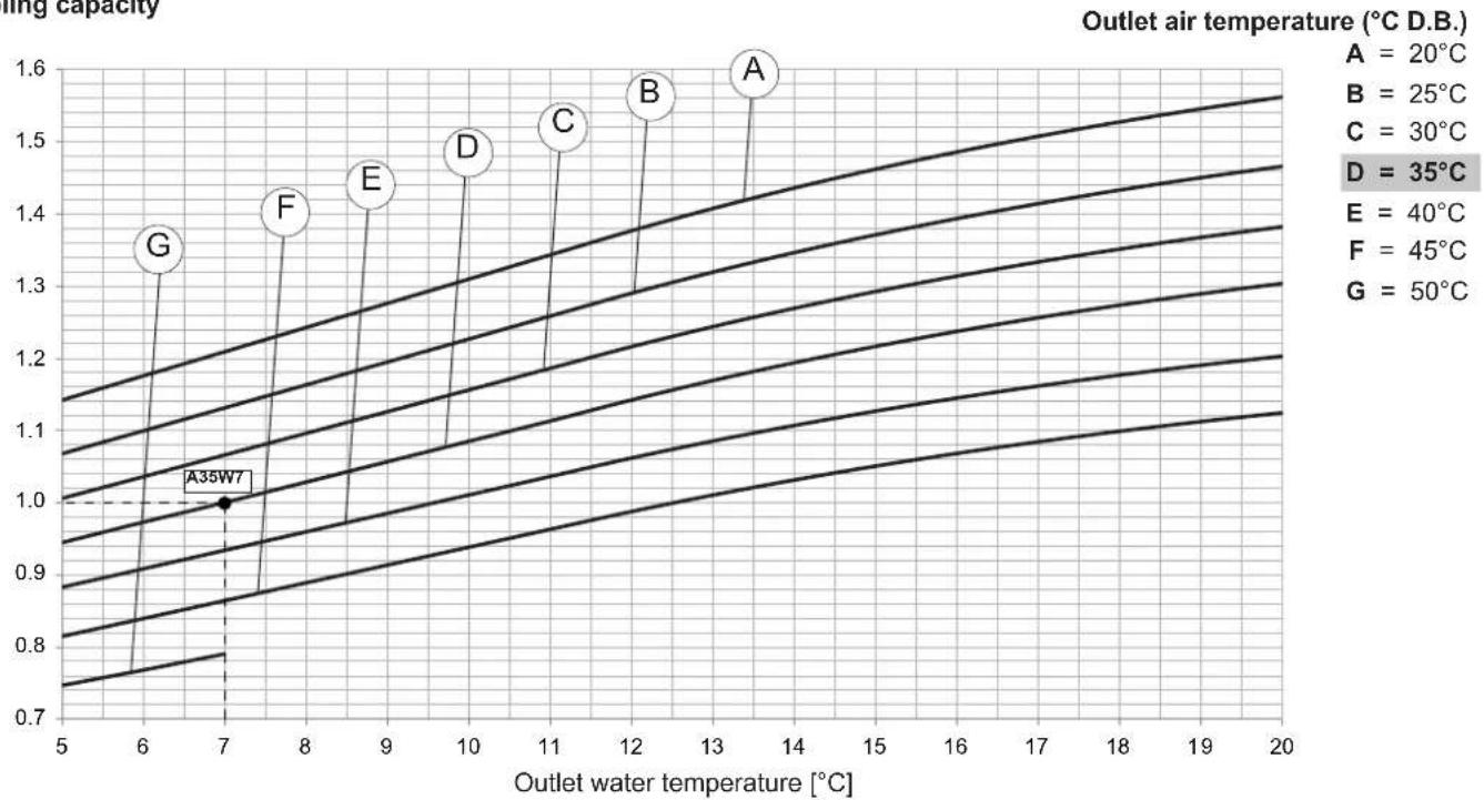
line
| Outlet water temperature [°C] | Outlet air temperature (°C D.B.) | | ----------------------------- | --------------------------------- | | 6 | 1.1 | | 7 | 1.0 | | 8 | 1.2 | | 9 | 1.3 | | 10 | 1.4 | | 11 | 1.5 | | 12 | 1.6 | | 13 | 1.5 | | 14 | 1.4 | | 15 | 1.3 | | 16 | 1.2 | | 17 | 1.1 | | 18 | 1.0 | | 19 | 0.9 | | 20 | 0.8 |Total power input

line
| Outlet water temperature [°C] | Outlet air temperature (°C D.B.) | | ----------------------------- | -------------------------------- | | 7 | 1.0 |The standard performances refer to a 5irc C temperature difference between the water entering and leaving the heat exchanger and to operation of the unit with all fans at nominal or maximum speed. A 0.44 × 10⁻⁴ m 2 K/W fouling factor has also been considered with the unit installed at zero meters above sea level (Pb = 1013mbar).
TECHNICAL DATA AND PERFORMANCE - BASE VERSION (VB)
HEATING performances
The graphs allow to get the corrective factors to be applied to the nominal performances in order to obtain the real performances in the selected operating conditions. For the "Operation limits" of the unit refer to the section limits.
The reference nominal condition is: A7W45 (source : air in 7°C d.b. 6°C w.b. / plant : water in 40°C out 45°C)
Heating capacity
Outlet air temperature (°C D.B. / W.B.)

line
| Outlet water temperature [°C] | Value | | ------------------------------ | ----- | | 36 | 1.2 | | 39 | 1.2 | | 42 | 1.2 | | 45 | 1.2 | | 48 | 1.2 | | 51 | 1.2 | | 53 | 1.0 | | 54 | 1.0 |Total power input
Outlet air temperature (°C D.B. / W.B.)

line
| Point | Outlet water temperature [°C] | Value Label | |-------|-------------------------------|-------------| | A | 37 | A | | B | 43 | B | | C | 49 | C | | D | 53 | D | | E | 55 | E | | F | 58 | F | | G | 60 | G | | D = 7 / 6°C | 54 | D = 7 / 6°C | E = 10,1 / 9°C, F = 13,2 / 12°C, G = 16,4 / 15°CThe standard performances refer to a 5irc C temperature difference between the water entering and leaving the heat exchanger and to operation of the unit with all fans at nominal or maximum speed. A 0.44 × 10⁻⁴ m 2 K/W fouling factor has also been considered with the unit installed at zero meters above sea level (Pb = 1013mbar).
NOTE For air temperatures of less than 7irc C, the heating capacity is declared without considering the effect of the defrosting, strictly correlated with the humidity in the outdoor air.
BR - BP UNIT
Corrective factors
Correction factors to apply to the basic version data.
ETHYLENE GLYCOL
| Percentage Of glycol in mass / volume 20 / | 18,1 | ||||||||
| Freezing point [°C] -8 | |||||||||
| Produced water temperature 4 2 0 -2 -4 | -6 | -8 | -10 | -12 | |||||
| CCPF - Cooling capacity | 0,912 | 0,855 | 0,798 | 0,738 | 0,683 | --- | --- | --- | --- |
| CCPA - Power input | 0,967 | 0,957 | 0,947 | 0,927 | 0,897 | --- | --- | --- | --- |
| CCQA - Water flow rate | 1,071 | 1,072 | 1,073 | 1,075 | 1,076 | --- | --- | --- | --- |
| CCDP - Pressure drop | 1,090 | 1,095 | 1,100 | 1,110 | 1,120 | - | - | - | |
| Percentage Of glycol in mass / volume 30 / | 27,7 | ||||||||
| Freezing point [°C] | -14 | ||||||||
| Produced water temperature 4 2 0 -2 -4 | -6 -8 -10 | -12 | |||||||
| CCPF - Cooling capacity 0,899 0,842 0,785 0,725 | 0,670 0,61 | 3 0,562 -- | |||||||
| CCPA - Power input 0,960 0,950 0,940 0,920 0,890 | 0,870 0,840 -- | ||||||||
| CCQA - Water flow rate | 1,106 | 1,107 | 1,108 | 1,109 | 1,110 | 1,111 | 1,112 | - | - |
| CCDP - Pressure drop | 1,140 1, | 145 1,150 | 1,155 1,160 | 1,175 1, | 190 -- | ||||
| Percentage Of glycol in mass / volume 40 / 37,5 | |||||||||
| Freezing point [°C] | -22 | ||||||||
| Produced water temperature 4 2 0 -2 -4 | -6 -8 -10 | -12 | |||||||
| CCPF - Cooling capacity 0,884 0,827 0,770 0,710 | 0,655 0,598 | 0,547 0,490 | 0,437 | ||||||
| CCPA - Power input 0,880 0,870 0,860 0,840 0,810 | 0,790 0,760 | 0,724 | 0,686 | ||||||
| CCQA - Water flow rate 1,150 1,151 1,153 1,154 1,155 | 1,157 | 1,158 | 1,159 | 1,161 | |||||
| CCDP - Pressure drop | 1,190 | 1,195 | 1,200 | 1,210 | 1,220 | 1,235 | 1,250 | 1,269 | 1,290 |
PROPYLENE GLYCOL
| Percentage Of glycol in mass / volume 20 / | 19,4 | ||||||||
| Freezing point [°C] -7 | |||||||||
| Produced water temperature 4 2 0 -2 -4 | -6 | -8 | -10 | -12 | |||||
| CCPF - Cooling capacity | 0,874 | 0,807 | 0,740 | 0,690 | 0,641 | --- | --- | --- | --- |
| CCPA - Power input | 0,945 | 0,935 | 0,925 | 0,900 | 0,875 | --- | --- | --- | --- |
| CCQA - Water flow rate | 1,037 | 1,038 | 1,039 | 1,039 | 1,040 | --- | --- | --- | --- |
| CCDP - Pressure drop | 1,110 | 1,115 | 1,120 | 1,130 | 1,140 | - | - | ||
| Percentage Of glycol in mass / volume 30 / | 29,4 | ||||||||
| Freezing point [°C] | -13 | ||||||||
| Produced water temperature 4 2 0 -2 -4 | -6 -8 -10 | -12 | |||||||
| CCPF - Cooling capacity 0,869 0,799 0,729 0,680 | 0,630 0,58 | 3 0,536 -- | |||||||
| CCPA - Power input 0,935 0,923 0,910 0,888 0,865 | 0,838 0,810 -- | ||||||||
| CCQA - Water flow rate 1,072 1,071 1,070 1,069 1,069 1,068 | 1,067 -- | ||||||||
| CCDP - Pressure drop | 1,160 1,175 1,190 | 1,200 1,210 | 1,255 1,300 -- | ||||||
| Percentage Of glycol in mass / volume 40 / 39,6 | |||||||||
| Freezing point [°C] | -21 | ||||||||
| Produced water temperature 4 2 0 -2 -4 | -6 -8 -10 | -12 | |||||||
| CCPF - Cooling capacity 0,848 0,784 0,719 0,670 | 0,620 0,570 | 0,520 0,478 | 0,438 | ||||||
| CCPA - Power input 0,865 0,855 0,845 0,820 0,795 | 0,773 0,750 | 0,714 | 0,680 | ||||||
| CCQA - Water flow rate | 1,116 | 1,114 | 1,112 | 1,110 | 1,108 | 1,107 | 1,105 | 1,103 | 1,101 |
| CCDP - Pressure drop | 1,230 | 1,275 | 1,320 | 1,375 | 1,430 | 1,500 | 1,570 | 1,642 | 1,724 |
Based on leaving water temperature of the evaporator and condensing temperature = 7irc C extract Cooling Capacity (kWf) and Compressors Power Input (kWa).
Based on type and percentage of glycol extract CCPF, CCPA, CCQA, CCDP.
Then calculate.
Pf brine = kWf x CCPF
Pass_CP_brine = kWa x CCPA
Then calculate brine flow rate:
Q_brine_evap [l/s]=CCQA x (Pf_brine [kW]*0.86/ΔT_brine)/3.6
where ΔT brine is the difference between inlet-outlet evaporator water temperature:
ΔT brine=Twin_evap_brine-Twout_evap_brine
With this brine flow rate enter in abscissa on the water pressure drop of the evaporator then you have Dp_app.
Finally you can calculate the actual pressure drop of the brine on evaporator side:
Dp_evap_brine =CCDP x Dp_app
BR and BP units must be used with a mixture of water and antifreeze fluid (eg glycol) in a percentage enough to prevent freezing of the mixture under all possible conditions, otherwise it will VOID THE WARRANTY.
Please contact our customer service to set the following parameters: →
| Parameter to set | Default value | How to calculate the value to set | Example with TWE = 0°C | Example with TWE = -5°C |
| tr-06 | 7 °C | TWE +5°C | +5 °C | 0 °C |
| tr-04 | 12 °C | TWE +5°C | +5 °C | 0 °C |
| HI-06 | 5 °C | TWE -2°C | -2 °C | -7 °C |
| RL-12 | 4,5 °C | TWE -3°C | -3 °C | -8 °C |
TWE= Evaporator outlet desired water temperature
NOISE LEVELS
Base setting up (AB)
| Model | Sound power levels [dB] by octave bands [Hz] | Sound power level | Sound pressure level | |||||||||||
| at 1 metre at 5 metres | at 10 metres | |||||||||||||
| 63 | 125 | 250 | 500 | 100 | 00 | 200 | 4000 | 8000 [dB] [dB(A)] [dB(A)] [dB(A)] [dB(A)] E | ||||||
| 19.1 | 82,4 | 8 | 3,6 | 80,2 | 74,8 | 71,0 | 65,5 | 59,4 | 53,6 | 87 | 77 | 61 | 51 | 46 |
| 22.1 | 82,6 | 8 | 3,8 | 80,4 | 75,0 | 71,2 | 65,7 | 59,6 | 53,8 | 88 | 77 | 62 | 51 | 46 |
| 26.1 | 83,5 | 8 | 4,7 | 81,3 | 75,9 | 72,1 | 66,6 | 60,5 | 54,7 | 89 | 78 | 62 | 52 | 47 |
| 30.1 | 88,2 | 8 | 3,4 | 80,0 | 78,2 | 76,5 | 72,3 | 69,5 | 60,5 | 90 | 81 | 65 | 55 | 50 |
| 35.1 | 88,6 | 8 | 3,8 | 80,4 | 78,6 | 76,9 | 72,7 | 69,9 | 60,9 | 91 | 82 | 66 | 55 | 50 |
| 40.1 | 88,9 | 8 | 4,1 | 80,7 | 78,9 | 77,2 | 73,0 | 70,2 | 61,2 | 91 | 82 | 66 | 56 | 50 |
Low noise setting up (AS)
| Model | Sound power levels [dB] by octave bands [Hz] | Sound power level | Sound pressure level | |||||||||||
| at 1 metre | at 5 metres | at 10 metres | ||||||||||||
| 63 | 125 | 250 | 500 | 100 | 200 | 4000 | 8000 | [dB] [dB(A)] | [dB(A)] | [dB(A)] [dB(A)] | [dB(A)] | |||
| 19.1 | 80,3 | 8 | 1,5 | 78,1 | 71,7 | 66,9 | 61,2 | 54,9 | 49,1 | 85 | 74 | 58 | 48 | 43 |
| 22.1 | 80,5 | 8 | 1,7 | 78,3 | 71,9 | 67,1 | 61,4 | 55,1 | 49,3 | 85 | 74 | 59 | 48 | 43 |
| 26.1 | 81,4 | 8 | 2,6 | 79,2 | 72,8 | 68,0 | 62,3 | 56,0 | 50,2 | 86 | 75 | 59 | 49 | 44 |
| 30.1 | 86,9 | 8 | 2,1 | 78,7 | 75,9 | 73,2 | 68,8 | 65,8 | 56,8 | 89 | 78 | 62 | 52 | 47 |
| 35.1 | 87,5 | 8 | 2,7 | 79,3 | 76,5 | 73,8 | 69,4 | 66,4 | 57,4 | 90 | 79 | 63 | 53 | 48 |
| 40.1 | 87,9 | 8 | 3,1 | 79,7 | 76,9 | 74,2 | 69,8 | 66,8 | 57,8 | 90 | 79 | 63 | 53 | 48 |
Reference conditions
Performances referred to units operating in cooling mode at nominal conditions A35W7.
Unit placed in free field on reflecting surface (directional factor equal to 2).
The sound power level is measured according to ISO 3744 standard.
The sound pressure level is calculated according to ISO 3744 and is referred to a distance of 1/5/10 metres from the external surface of the unit.
(E): EUROVENT certifield data
ELECTRICAL DATA
Electrical data
| Frame | 1 | 2 | ||||||
| Model | 19.1 22 | 1 26.1 30.1 | 1 35.1 40.1 | U.M. | ||||
Unit
| Power supply 400-3N-50 400-3N-50 400-3N-50 400-3N-50 400-3N-50 400-3N-50 | ||||||||
| F.L.A. Maximum total current input 15,8 17,6 19,1 24,4 | A | |||||||
| F.L.I. Maximum total power input 9,2 10,7 12,0 14,6 16,1 18,4 | kW | |||||||
| M.I.C. | Maximum total start current 106 116 129 156 | A | ||||||
| Maximum total start current with soft starter (option) | 61 | 67 | 74 | 85 | 87 | 106 | A | |
Units with pumping module STD
| Power supply 400-3N-50 400-3N-50 400-3N-50 400-3N-50 400-3N-50 400-3N-50 | V-ph-Hz | |||||||
| F.L.A. Maximum total current input 17,3 19,1 20,6 26,0 | 28,4 32,4 | A | ||||||
| F.L.I. Maximum total power input 9,8 11,3 12,6 15,4 16,9 19,2 | kW | |||||||
| M.I.C. | Maximum total start current 107 117 130 158 | 162 193 | A | |||||
| Maximum total start current with soft starter (option) | 62 | 68 | 76 | 86 | 89 | 107 | A | |
Units with pumping module HP1
| Power supply 400-3N-50 400-3N-50 400-3N-50 400-3N-50 400-3N-50 400-3N-50 400-3N-50 | V-ph-Hz | |||||||
| F.L.A. Maximum total current input 17,5 19,3 20,8 27,4 | 29,8 33,8 | A | ||||||
| F.L.I. Maximum total power input 10,1 11,5 | 12,9 16,2 17,7 20,0 | kW | ||||||
| M.I.C. | Maximum total start current 108 118 131 159 | 163 194 | A | |||||
| Maximum total start current with soft starter (option) | 62 | 68 | 76 | 88 | 90 | 109 | ||
Integrative electrical heaters standard in the tank (option)
| Power supply | 400-3-50 | 400-3-50 | 400-3-50 | 400-3-50 | 400-3-50 | 400-3-50 | V-ph-Hz | |
| F.L.A. | Maximum total current input | 9,5 | 9,5 | 9,5 | 9,5 | 9,5 | 9,5 | A |
| F.L.I. | Maximum total power input | 6,6 | 6,6 | 6,6 | 6,6 | 6,6 | 6,6 | kW |
Compressor
| Power supply | 400-3-50 | 400-3-50 | 400-3-50 | 400-3-50 | 400-3-50 | 400-3-50 | V-ph-Hz | |
| F.L.A. Maximum total current input 14,6 16,4 17,9 20,3 | 22,7 26,7 | A | ||||||
| F.L.I. Maximum total power input 8,6 10,1 11,4 12,8 14,3 16,6 | kW | |||||||
| L.R.A. | Maximum total start current | 101 | 111 | 124 | 141 | 145 | 176 | A |
| Maximum total start current with soft starter (option) | 61 | 67 | 74 | 85 | 87 | 106 | A | |
Fan
| Power supply | 400-3-50 | 400-3-50 | 400-3-50 | 400-3-50 | 400-3-50 | 400-3-50 | V-ph-Hz | |
| F.L.A. Maximum total current input 1,20 1,20 1,20 4,10 4,10 4,10 | A | |||||||
| F.L.I. Maximum total power input 0,60 0,60 0,60 1,80 1,80 1,80 | kW | |||||||
| L.R.A. | Start current | 5,0 | 5,0 | 5,0 | 15,0 | 15,0 | 15,0 | A |
Standard THREE-PHASE pump (option)
| Power supply | 400-3-50 | 400-3-50 | 400-3-50 | 400-3-50 | 400-3-50 | 400-3-50 | V-ph-Hz | |
| F.L.A. Maximum total current input 1,45 1,45 1,45 1,58 1,58 1,58 | A | |||||||
| F.L.I. Maximum total power input 0,61 0,61 0,61 0,82 0,82 0,82 | kW | |||||||
| L.R.A. | Start current | 6,3 | 6,3 | 6,3 | 9,4 | 9,4 | 9,4 | A |
High head THREE-PHASE pump (option)
| Power supply | 400-3-50 | 400-3-50 | 400-3-50 | 400-3-50 | 400-3-50 | 400-3-50 | V-ph-Hz | |
| F.L.A. Maximum total current input 1,65 1,65 1,65 3,00 | 3,00 3,00 | A | ||||||
| F.L.I. Maximum total power input 0,88 0,88 0,88 1,60 | 1,60 1,60 | kW | ||||||
| L.R.A. | Start current | 9,9 | 9,9 | 9,9 | 16,3 | 16,3 | 16,3 | A |
OPERATING LIMITS
The table below lists the operating limits within which correct operation of the units is guaranteed, depending on the Version and Operating Mode available for each type of unit.
Remember that in Heat Pump units, heat recovery only takes place during operation in the cooling mode.
| Thermal gradient of the water Limit value | ||
| Minimum °C 3 | ||
| Maximum °C 8 | ||
| Verify that water flow rate is inside the admissible limits. | ||
NOTE: the admissible limits for water flow rate on heat exchangers are indicated under the related pressure drop graph (see section "water pressure drop"). If the unit is equipped with pumping module the admissible limits are indicated under the related working head graph (see section "working head").
STANDARD UNIT IR-IP
IN COOLING MODE
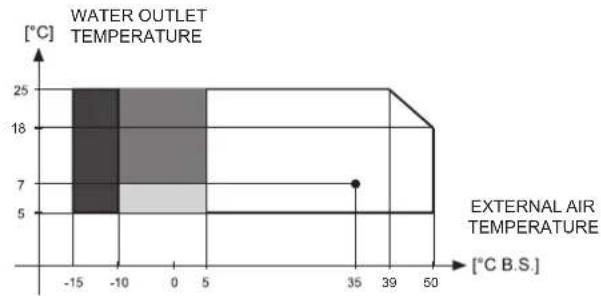
area
| Temperature Range | External Air Temperature (°C B.S.) | Water Outlet Temperature (°C) | | :--- | :--- | :--- | | -15 to -10 | 5 | 25 | | -10 to 0 | 7 | 25 | | 0 to 5 | 18 | 25 | | 5 to 39 | 25 | 25 | | 39 to 50 | 7 | 18 | The chart displays a single horizontal bar at the center, indicating that the temperature range is bounded by the external air temperature. The x-axis represents the temperature in °C B.S., and the y-axis represents the temperature in °C. The color-coded regions (dark gray for lower temperatures, light gray for higher temperatures) likely denote different temperature ranges or categories. The label 'WATER OUTLET TEMPERATURE' appears above the chart.
With fans modulating control options

With fans modulating control options and glicole water*

With fans modulating control options, glicole water* and "pressure transducer" accessory.
*: Or other antifreeze solutions
IN HEATING MODE

line
| External Air Temperature [°C B.S.] | Water Outlet Temperature [°C] | | ----------------------------------- | ------------------------------ | | -15425 | 45 | | 7 | 55 | | 30 | 30 |
With fans modulating control options
BRINE UNIT BR - BP
For these applications requires the use of brine or other antifreeze solutions.
IN COOLING MODE

line
| External Air Temperature [°C B.S.] | Temperature [°C] | | ---------------------------------- | ----------------- | | -15 | 5 | | -10 | -5 | | 0 | -12 | | 35 | -5 | | 40 | -12 | | 50 | 5 |
With fans modulating control options

With fans modulating control options and "pressure transducer" accessory.
IN HEATING MODE

line
| External Air Temperature [°C B.S.] | Water Outlet Temperature [°C] | | ---------------------------------- | ------------------------------ | | -15425 | 45 | | 7 | 55 | | 30 | 55 |
With fans modulating control options
Pressure drops - unit without options

line
| Pressure drops [kPa] | Value | | --------------------- | ------ | | 19.1 | 19.1 | | 22.1 | 22.1 | | 30.1 | 30.1 | | 35.1 | 35.1 |Flow rate [l/h]
| MODELS 19.1 22.1 26.1 30.1 35.1 40.1 UM NOTE | ||||||||||
| Lower limit value Q | 2500 | 3000 | 3500 | 4000 | 4500 | 5250 | lh | |||
| Upper limit value Q | 8500 | 10000 | 11500 | 12500 | 140000 | 14000 | lh | |||
The graphs are referred to units operating with water at the temperature of 10ircC (density 1000kg / m3 ).
Available static head - unit with option "Storing and pumping module" : "Standard pump" or "Tank and standard pump" "Modulating pump" or "Tank and modulating pump"
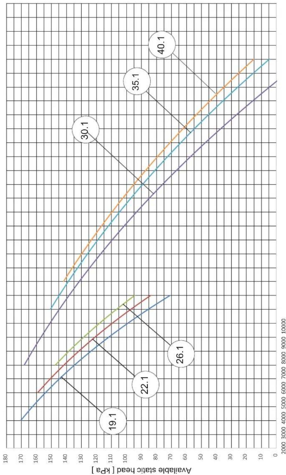
line
| X Value | Available static head [kPa] | | ------- | --------------------------- | | 4000 | 19.1 | | 6000 | 22.1 | | 8000 | 26.1 | | 10000 | 30.1 | | 12000 | 35.1 | | 14000 | 40.1 |Flow rate [l/h]
| MODELS 19.1 22.1 26.1 30.1 35.1 40.1 UM NOTE | |||||||||||
| Lower limit value Q | 2500 | 300 | 00 | 3500 | 4000 | 4500 | 5250 | lh | |||
| Upper limit value Q | 4750 | 7800 | 00 | 8500 | 8900 | kPa | |||||
The graphs are referred to units operating with water at the temperature of 10irc C (density 1000 kg/m3 ).
Available static head - unit with option "Storing and pumping module": "High head pump" or "Tank and high head pump"
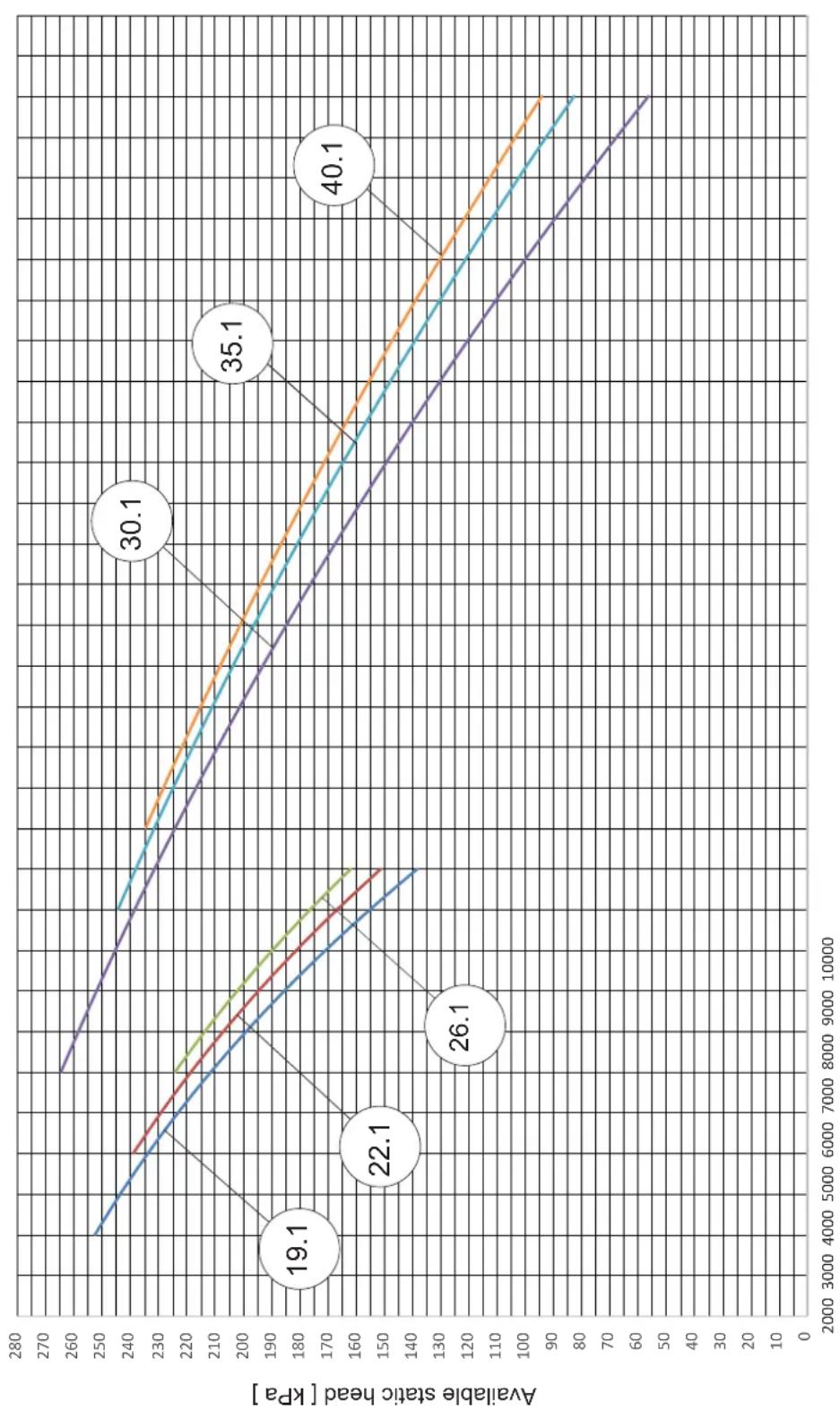
line
| Available static head [kPa] | Value | | --------------------------- | ----- | | 19.1 | 19.1 | | 22.1 | 22.1 | | 26.1 | 26.1 | | 30.1 | 30.1 | | 35.1 | 35.1 | | 40.1 | 40.1 |Flow rate [ l/h ]
| MODELS 19.1 22.1 26.1 30.1 35.1 40.1 UM NOTE | |||||||||
| Lower limit value Q | 2500 | 30 | 00 | 3500 | 400 | 0 | 4500 | 5250 | lh |
| Upper limit value Q | 4750 | 950 | 0 | kPa | |||||
The graphs are referred to units operating with water at the temperature of 10irc C (density 1000 kg/m3 ).
DIMENSIONAL AND PHYSICAL DATA
Overall dimensions
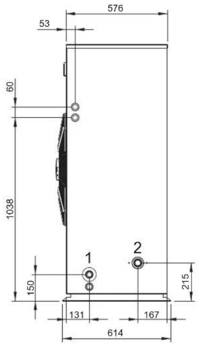

| Frame | 1 | 2 | ||||||
| Model | 19.1 22.1 | 26.1 30.1 | 35.1 40.1 | |||||
| Plant return | 1 1"1/4 | F 1"1/4 | F 1"1/4 | F 1"1/4 F 1"1/4 F 1"1/4 F | - | |||
| Plant flow | 2 1"1/4 | M 1"1/4 | M 1"1/4 | M 1"1/4 M 1"1/4 M 1"1/4 M 1"1/4 M | - | |||
| D 1494 | 1704 | mm | ||||||
| E 728 938 | mm | |||||||
Minimum operating area
Respect the free area around the unit as shown in the figure in order to guarantee a good accessibility and facilitate maintenance and control operations.
| A 400 mm |
| B 600 mm |
| C 200 mm |

natural_image
Isometric technical drawing of a large industrial fan or compressor unit with labeled dimensions A, B, and C (no text or symbols beyond labels)DIMENSIONAL AND PHYSICAL DATA
Weights
| Frame | 1 | 2 | ||||||
| Model | 19.1 22 | 1 26.1 30.1 | 1 35.1 40.1 | U.M. | ||||
Empty weight
| Unit without options 235 238 261 280 303 305 | kg | ||||||||
| Options | Storing and pumping module | Standard pump 9 9 9 9 11 11 | kg | ||||||
| High head pump 12 12 12 12 13 | 13 | kg | |||||||
| Modulating pump 12 12 12 14 16 | 16 | kg | |||||||
| Tank and standard pump | 31 31 31 | 31 33 33 | kg | ||||||
| Tank and high head pump | 34 34 34 | 34 35 35 | kg | ||||||
| Tank and modulating pump | 34 34 34 | 36 38 38 | kg | ||||||
| Integrative electrical heaters | Standard in the tank 5 5 5 5 5 5 | kg | |||||||
Transport weights
| Unità senza opzioni 251 254 277 300 323 325 | kg | ||||||||
| Options | Storing and pumping module | Standard pump 9 9 9 9 11 11 | kg | ||||||
| High head pump 12 12 12 12 13 | 13 | kg | |||||||
| Modulating pump 12 12 12 14 16 | 16 | kg | |||||||
| Tank and standard pump | 31 31 31 | 31 33 33 | kg | ||||||
| Tank and high head pump | 34 34 34 | 34 35 35 | kg | ||||||
| Tank and modulating pump | 34 34 34 | 36 38 38 | kg | ||||||
| Integrative electrical heaters | Standard in the tank | 5 5 5 5 | 5 5 | kg | |||||
Operating weights
| Unità senza opzioni 239 242 266 285 309 311 | kg | ||||||||
| Options | Storing and pumping module | Standard pump | 10 10 10 | 10 12 12 | kg | ||||
| High head pump 13 13 13 13 14 | 14 | kg | |||||||
| Modulating pump 13 13 13 15 17 | 17 | kg | |||||||
| Tank and standard pump | 117 | 117 | 117 | 117 | 119 | 119 | kg | ||
| Tank and high head pump | 120 120 | 120 120 121 | 121 | kg | |||||
| Tank and modulating pump | 120 120 | 120 122 124 | 124 | kg | |||||
| Integrative electrical heaters | Standard in the tank 5 5 5 5 5 5 | kg | |||||||
RECEPTION AND POSITIONING
Receiving
Check on receiving
As soon as the unit is received verify accurately the correspondence of the load to what was ordered to make sure that all the material has been delivered. Check carefully that the load has not been damaged. In case of goods with visible damages inform promptly the haulage contractor reporting on the delivery note the phrase “Collected with reserves owing to evident damage”. Delivery ex works implies reimbursement of any damage on charge of the insurance company as established by law.
Safety instructions
Observe the safety regulations in force concerning the equipment to use for unit handling or the operating formalities to follow.
Handling
Before handling the unit, check the weight of the unit, reported both on the dataplate and on the technical documentation. Make sure the unit to be handled with care avoiding any kind of collision that could damage the operating parts of the unit.
On the packaging of the unit are reported all the instructions
necessary for a corect handling during storing and installation.
The unit is supplied on a pallet suitable for the transport. It is advisable to place protective material between the truck and the unit to avoid damages to the unit. Prevent the unit or parts of it from falling down.
Storing
The units must be stored in a dry place, repaired from sun, rain, sand or wind.
Do not stack the units.
Maximum temperature = 60 °C
Minimum temperature = -10 °C
Humidity = 90 %
Packaging removal
Remove the packaging taking care not to damage the unit.
Check for any visible damage.
Get rid of the packaging material sending them to specialized recycling centres (observe the regulations in force).
Positioning
The units are suitable for outdoor installation.
Verify that the support surface can bear the weight of the selected unit and is perfectly horizontal. In order to limit the vibrations transmitted by the unit it is possible to place, between the unit base and the support surface, a strip of hard rubber or, if a higher level of insulation is required, vibration dampers.
In any case it is not advisable to place the unit near private offices, bedrooms or zones where very low noise levels are required.
Protect the finned coil against direct sunlight and prevailing winds and do not place the unit on dark ground (for example tarred surfaces) to avoid the risk of overheating during operation.
Do not place the unit under roofs or near plants (even if the unit is only partly covered) in order not to reduce the possibility of air recirculation.
Respect the minimum operating area and verify that the installation place is not subject to flooding.
HYDRAULIC CONNECTIONS
General rules
A mesh filter (hole <0.5mm for plates heat exchanger) must be installed on the unit's water inlet otherwise warranty is immediately forfeited. The filter performs the function of blocking any foreign matter in the system's plumbing circuit (shavings, machining debris, etc.) limiting or avoiding possible problems of fouling (that decreases the heat exchange coefficient), erosion, and clogging
The clogging and fouling of the exchanger can lead to a reduction of the water flow rate and. In the case that the exchanger works as evaporator- of the evaporation temperature: these 2 factors can cause the icing of the exchanger
The icing event leads to the bursting of the exchanger, the inlet of water into the refrigerant circuit and so the necessity of a replacement of the main components (compressors, filters, expansion valves,. Etc.) and an accurate washing of components as refrigerant pipes, coils, etc., practically the rebuilding nearly complete of the refrigerant circuit.
The filter must be maintained clean: this is so necessary to verify the cleanness after the unit installation and checking periodically the state.
Protection devices
Standard supply includes a differential pressure switch situated between the water inlet and outlet of the heat exchanger to avoid freezing if the water flow stops for any reason.
- Standard supply includes an antifreeze heater placed between the external thermal insulation and the shell of the exchanger and controlled by the main electronic controller of the unit in order to protect the evaporator full of water (but not the pipes) from the winter icing when the unit is in stand-by mode. The exchanger is protected down to an outdoor air temperature of -20ircC .
NOTE the antifreeze protection only work if the unit is electrically connected the standby period.
It is recommended to install a water paddle flow switch at the water inlet of the unit: the water paddle flow switch has to be electrically wired in series with the differential pressure switch.
It is mandatory to calibrate the trip out of the water paddle flow switch at a water flow rate value higher than the minimum water flow rate admissible for the exchanger (re. section Pressure Drop).
Tips for a successful installation
For a correct design and installation of the hydraulic plant comply the local laws governing safety matters and sound...
The following information is suggestion for a correct installation of the unit:
- Before connecting the unit to the system wash adequately the pipes using clean water, filling and emptying and cleaning the filters.
Only after that proceed connecting the unit to the system; this operation is crucial to ensure proper start-up without the need to have repeated stops to clean the filter, with the possible risk of damage to heat exchangers and other components.
- Check by qualified personnel the quality of the water or of the mixture used; avoid the presence of inorganic salts, biological load (seaweeds,
etc.) suspended solids, dissolved oxygen and the pH. Water with inadequate characteristics can cause a pressure drop increase due to a rapid fouling of the filter, energy efficiency decrease and corrosive symptom increase that can damage the unit.
- The pipes must have the least possible number of bends to minimize load losses and must be adequately supported in order to prevent the connections of the unit from being excessively stressed.
• Install on-off valves near components that need to be serviced to isolate them when maintenance work needs to be done and to allow them to be replaced without having to discharge the system.
- Before isolating the pipes and charging the system, carry out preliminary inspections to make sure that there are no leaks.
- Isolate all the chilled water pipes to prevent condensation from forming along the pipes themselves. Make sure that the material used is the steam barrier type, failing this, cover the insulation with an appropriate protection. Also make sure that the air venting valves can be accessed through the insulation.
- Do not forget to install or at least allow for the installation of pressure and temperature reading instruments on the inlet and outlet parts of the hydraulic circuit. These instruments will allow you to monitor the operation of the system.
- The circuit can be kept under pressure by means of an expansion tank and a pressure reducer. A plant filling unit can also be used in order to automatically charge the system and keep it at the desired pressure if it drops below a certain pressure value. Install manual or automatic values in the highest point of the system to eliminate air from the circuit.
Fit manual or automatic valves at the highest point in the circuit in order to vent air from the circuit.
- the water connections are Victaulic-type joints for hooking up to the unit.
The joints allow the pipes to expand due to changes in temperature and in addition the elastomer gasket and the specified play help insulate and absorb noise and vibration.
- If vibrations dampers are installed under the unit, it is recommended to use flexible couplings before and after the water circulation pump and near the unit.
• Install on the outlet of the unit a suitable valve able to regulate the water flow.
- Avoid that the weight of the connection pipes pushes on the hydraulic connections of the unit using approved supports.
Check that plant components are suitable to bear the maximum static pressure (it depends on the height of the building).
ATTENTION
For units in VP version equipped with expansion vessel is required to install a safety valve (SET = 3 bar) on the hydraulic circuit. If the unit is disconnected from the rest of the hydraulic system with shut-off valve or other equivalent device (eg during maintenance), check that the safety valve is always connected with the expansion vessel. See diagram:
| ITEM DESCRIPTION | |
| P | PUMP |
| PD | DIFFERENTIAL PRESSURE WATER |
| RA | SUCTION BALL VALVE |
| RM | DISCHARGE BALL VALVE |
| SIW | PROBE WATER INLET |
| SP | HEAT EXCHANGER |
| SUW | PROBE WATER OUTLET |
| VS | SAFETY VALVE |
| VE | EXPANSION TANK |
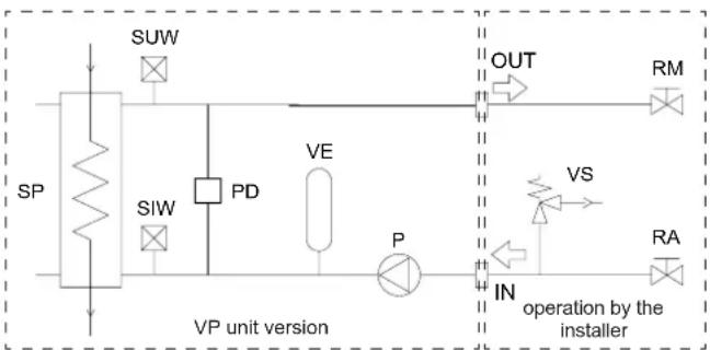
flowchart
graph TD
    SP -->|SP| A["Valve"]
    A --> B["SUW"]
    A --> C["SIW"]
    C --> D["PD"]
    D --> E["VE"]
    E --> F["P"]
    F --> G["OUT"]
    G --> H["VS"]
    H --> I["IN"]
    I --> J["RA"]
    J --> K["Operation by the installer"]
    style A fill:#f9f,stroke:#333
    style K fill:#ccf,stroke:#333
HYDRAULIC CONNECTIONS
Water component for corrosion limit
To avoid corrosion problems in water exchangers make sure that the water used in the plant meets the requirements listed in the table.
| pH 7.5 ÷ 9.0 - | ||
| SO4 -- < 100 ppm | ||
| HCO3-/SO4 -- >1.0 | ||
| Total hardness 8.0 ÷ 15.2 °F | ||
| Cl- < 50 ppm | ||
| PO4 3- < 2.0 ppm | ||
| NH3 < 0.5 ppm |
| Free Chlorine < 0 | 5 ppm | |
| Fe3+ | < 0.5 ppm | |
| Mn++ | < 0.05 | ppm |
| CO2 | < 50 ppm | |
| H2S | < 50 | ppb |
| Temperature | < 65 | °C |
| Oxygen content | < 0.1 ppm |
Precautions for the Winter
The water could freeze and damage the exchanger of the unit and other parts of the system during the winter period, if the system was to remain at a standstill. This problem can be obviated in 3 different ways:
-
Drain the system completely, taking care to drain the plate exchanger (in order to drain the unit's piping system completely, open the water drain ball valves and the air vent valves, open any valves closed).
-
Operate with glycol water taking account, depending on the % of glycol, of the factor of correction of the refrigerating capacity, power input, water flow rate and losses of head (see table on following page)
-
If it is certain that the unit will always be powered throughout the winter, the unit is able to protect itself from freezing, down to a temperature of -20ircC : this is possible thanks to an antifreeze electric heating element installed on the plate exchanger and intelligent control of the water pump that must be governed by the microprocessor board (see the “Electric Connections” section).
If the unit is fitted with a Storage tank, solution no. 3 requires installing the tank antifreeze heating element accessor.
Air vent and water drain
On the plumbing circuit feeding the unit, the installer must fit an appropriate number of valves (manual or automatic) at the top of the circuit in order to vent any air in the plumbing system. In the same way, he must install a water drain valve in order, when necessary, to drain the unit's plate exchanger completely (especially during the winter in order to prevent freezing that would seriously jeopardize the operation of the unit).
Maximum volume of water in the system with wet module
Before filling the water system, it is advisable to consider the type of installation in question, i.e. check the difference in level between the wet module and user. The following table gives the maximum water content of the water supply system in liters, depending on the capacity of the standard expansion vessel supplied and the pressure at which it should be charged. The expansion vessel setting must be regulated to suit the maximum positive difference in level of the user.
Maximum setting value 600 kPa.
With a positive H of more than 12.25 meters, calculate the expansion vessel precharge value in kPa using the formula below:
Expansion vessel precharge= [H/10.2+0.3] x100 = [kPa]
NOTE. In case A, make sure that the user's lowest point is able to withstand the global pressure.
Tab.1
| Expansion vessel volume (liters) | 10 | |||
| Safety valve set (bar) | 3 | |||
| Thermal expansion of water (10-40°C) | 0.0074 | |||
| Thermal expansion of water (10-60°C) | 0.0167 | |||
| H (metri) | Expansion vessel pressure (bar) | IR | IP | |
| Case A | H < 0 | 1 | 667 | 299 |
| Case B | 0 < H < 17 | 1 | 667 | 299 |
| 12 | 1,5 | 500 | 225 | |
| 15 | 1,8 | 400 | 180 | |
| 20 | 2,3 | 233 | 105 | |

NOTE: If the unit operates with brine, calculate the real volume of the system by taking into account the corrective factors for the volume of the system given in the table below.
Corrective factors per total maximum volume of the system with brine
| % of brine | 0% | 10% | 20% | 30% | 40% |
| Cooling Mode | 1,000 | 0,738 | 0,693 | 0,652 | 0,615 |
| Heating Mode | 1,000 | 0,855 0,811 0,769 | 0,731 |
Electrical connections
The electrical wirings must be carried out by qualified personnel according to the regulations in force at the installation time in the country of installation. Before starting any work on the electrical circuit make sure that the unit power supply line is disconnected at the start.
N.B. Refer to the electrical diagram enclosed in the unit.
Power supply system
The power cables of the heat pump power supply line must be connected to :
- for single phase power supply : from a single phase voltage system provided with neutral conductor and separated earth wire :
V = 230 V ± 10 %
f = 5 0 Hz
- for three phase power supply : from a symmetrical three phase voltage system provided with neutral conductor and separated earth wire :
V = 3 8 0 ÷ 4 2 0 V
f = 5 0 Hz
The units are shipped completely factory wired and arranged for the connection to the power supply.
The power cables must enter the unit through the holes on the lateral panel and must be connected to the power supply terminals of the unit.
The integrative electrical heaters (option) must be supplied by a dedicated power supply line to be connected to the power supply terminals inside the electrical board of the unit.
Unit power supply
The power supply cables must have an adequate section for the power absorbed by the unit and must be chosen in conformity with the regulations in force. Design the power supply line, always referring to the total FLI and FLA values of the unit, taking into account the selected options (except the integrative electrical heaters) and the installed accessories.
The power supply cables must have an adequate section for the power absorbed by the only integrative electrical heaters and must be chosen in conformity with the regulations in force.
The electrical heaters must be connected to a single phase power supply if the unit power supply is single phase or to a three phase power supply if the unit power supply is three phase.
Upstream protection
An automatic switch suitable for ensuring protection against overcurrents and indirect contacts must be installed upstream each power supply line.
Coordination between line switch must be carried out observing the regulations in force on electrical safety, regarding the type of installation and the installation ambient conditions.
Connections available for the user
The wiring board inside the electrical panel contains dedicated terminals for the following connections.
General alarm
Voltage output (230V - max 2A) to be used to notify the presence of an active alarm.
Output active : active alarms
Output not active : no active alarms
Remote stand by
To turn on and off the unit, a remote device (selector, programmer clock, centralised supervision device ...) with a voltage free contact suitable for switching loads of very low power, can be connected.
This function must be enabled by parameter (see the section "Adjustment and control") and prevails the settings made on the user interface.
Remote Cooling-Heating
It is possible to switch between cooling mode and heating mode from remote by connecting a device equipped with a voltage free contact suitable for switching loads of very low power.
This function must be enabled by parameter (see the section "Adjustment and control") and prevails the settings made on the user interface.
Remote control
It is possible to connect a remote control that has all the control and display functions available on the user interface on the unit and therefore enables the complete remote control of the unit.
Pump control
The controller of the unit can directly activate the circulating pump by means of a voltage free contact (maximum absorbed current 4A).
ATTENTION
Carry out all the connections outside the unit avoiding the power cables and the probe cables to be coupled.
R410A PROTECTION DEVICES
Protection devices HIGH PRESSURE
| LEVEL | 1 |
| Device | High pressure automatic switch |
| Trip out (barg) | 41.0 |
| Trip in (barg) | 29.5 |
| connected to | electronic controller |
| effect | stop the compressors and the fans of that circuit |
| reset * | YES by keyboard if the high pressure switch has trip-in and after the solution of the problem that generates the alarm |
*: For more details refers to section monitoring basic system.
Protection devices LOW PRESSURE
| LEVEL 1 | |
| Device | Low pressure automatic switch |
| Trip out (barg) | 4 bar (IR, IP unit in cooling mode) 2 bar (BR,BP, IP unit in heating mode) |
| Trip in (barg) | 6 bar (IR, IP unit in cooling mode) 4 bar (BR,BP, IP unit in heating mode) |
| connected to | electronic controller |
| effect | stop the compressors of that circuit |
| reset * | YES by keyboard if the low pressure switch has trip-in and after the solution of the problem that generates the alarm |
*: For more details refers to section monitoring basic system.
REFRIGERANT FLOW DIAGRAM
IR unit

flowchart
graph TD
    A["VSW"] --> B["R2"]
    B --> C["R1 / RAG"]
    C --> D["VI"]
    D --> E["OUT"]
    F["VES"] --> G["SFA"]
    G --> H["VA"]
    I["P"] --> J["FW"]
    J --> K["VI"]
    K --> L["VP + VA"]
    M["CP"] --> N["PP6"]
    N --> O["MAP"]
    P["PP5"] --> Q["MBP"]
    Q --> R["*"]
    S["PE"] --> T["PD"]
    U["VD"] --> V["FD"]
    W["SW"] --> X["SIW"]
    Y["PC"] --> Z["PP1"]
    AA["STAE"] --> AB["BE"]
    AC["SL**"] --> AD["PP3"]
    AE["TPL*"] --> AF["PP3"]
    style A fill:#f9f,stroke:#333
    style B fill:#f9f,stroke:#333
    style C fill:#f9f,stroke:#333
    style D fill:#f9f,stroke:#333
    style E fill:#f9f,stroke:#333
    style F fill:#f9f,stroke:#333
    style G fill:#f9f,stroke:#333
    style H fill:#f9f,stroke:#333
    style I fill:#f9f,stroke:#333
    style J fill:#f9f,stroke:#333
    style K fill:#f9f,stroke:#333
    style L fill:#f9f,stroke:#333
    style M fill:#f9f,stroke:#333
    style N fill:#f9f,stroke:#333
    style O fill:#f9f,stroke:#333
    style P fill:#f9f,stroke:#333
    style Q fill:#f9f,stroke:#333
    style R fill:#f9f,stroke:#333
    style S fill:#f9f,stroke:#333
    style T fill:#f9f,stroke:#333
    style U fill:#f9f,stroke:#333
    style V fill:#f9f,stroke:#333
    style W fill:#f9f,stroke:#333
    style X fill:#f9f,stroke:#333
    style Y fill:#f9f,stroke:#333
    style Z fill:#f9f,stroke:#333
    style AA fill:#f9f,stroke:#333
    style AB fill:#f9f,stroke:#333
    style AC fill:#f9f,stroke:#333
    style AD fill:#f9f,stroke:#333
* : Optional / accessory
** : Do not installed if present TPL accessory
| ID DESCRIPTION | |
| BE | finned coil |
| CB | Capillary by-pass |
| CP | compressor |
| FD | filter dryer |
| MAP | High pressure gauge |
| MBP | Low pressure gauge |
| PA | High pressure |
| PB | Low pressure |
| PD | differential pressure |
| ID DESCRIPTION | |
| PP | Outlet pressure |
| SC | Plate heat exchanger |
| SIW | Probe inlet water |
| SL | probe liquid |
| STAE | Outside air sensor |
| SUW | Water outlet probe |
| TPL | Liquid pressure transducer |
| VE | fan |
| VT | thermostatic valve |
IP unit

flowchart
graph TD
    A["VES"] --> B["SFA"]
    C["VSW"] --> D["R2 / RAG"]
    D --> E["VI"]
    E --> F["OUT"]
    G["VA"] --> H["FIW"]
    H --> I["P"]
    I --> J["N"]
    K["PD"] --> L["SIW"]
    L --> M["SC"]
    N["SPV + VA"] --> O["P"]
    P["OUT"] --> Q["IN"]
    R["VA"] --> S["FIW"]
    T["VA"] --> U["FIW"]
    V["VA"] --> W["FIW"]
    X["VA"] --> Y["FIW"]
    Z["VA"] --> AA["FIW"]
    AB["SUW"] --> AC["SC"]
    AD["PD"] --> AE["SC"]
    AF["SIW"] --> AG["SC"]
    AH["S4"] --> AI["SC"]
    AJ["S3"] --> AK["SC"]
    AL["RIC"] --> AM["CB"]
    AN["VC"] --> AO["MAP"]
    AP["PA"] --> AQ["PP2"]
    AR["CP"] --> AS["PP6"]
    AT["PD"] --> AU["PP4"]
    AV["PD"] --> AW["PD"]
    AX["PD"] --> AY["PD"]
    AZ["PD"] --> BA["PD"]
    BB["PD"] --> BC["PD"]
    BD["BE"] --> BE1["STAE"]
    BE1 --> BL["SL**"]
    BL --> BL1["TPL*"]
    BL1 --> BL2["PP3"]
    BL2 --> BL3["PP5*"]
    BL3 --> BL4["PP1"]
    BL4 --> BL5["MBP"]
* : Optional / accessory
** : Do not installed if present TPL accessory
| ID DE$CRIPTION | |
| BE | finned coil |
| CB | Capillary by-pass |
| CP | compressor |
| FD | filter dryer |
| MAP | High pressure gauge |
| MBP | Low pressure gauge |
| PA | High pressure |
| PB | Low pressure |
| PD | differential pressure |
| PP | Outlet pressure |
| ID DE$CRIPTION | |
| RIC | Liquid receiver |
| SC | Plate heat exchanger |
| SIW | Probe inlet water |
| SL | probe liquid |
| STAE | Outside air sensor |
| SUW | Water outlet probe |
| TPL | Liquid pressure transducer |
| VE | fan |
| VT | thermostatic valve |
CONTROL SYSTEM
Control system
The unit is managed by a microprocessor controller to which, through a wiring board, all the electrical loads and the control devices are connected. The user interface is realized by a display and four buttons that allow to view and, if necessary, modify all the operating parameters of the unit. It's available, as an accessory, a remote control that reports all the functionalities of the user interface placed on the unit. The interface, placed on the frontal panel of the unit, is accessible from the outside and is protected by a transparent plastic door.
It's available, as an accessory, a remote control that reports all the functionalities of the user interface placed on the unit.
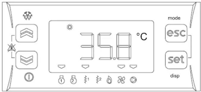
To each button are associated :
- a direct function : indicated on the button itself and activated pressing the button
- an associated function : indicated on the front of the instrument at the corresponding button and activated pressing the button for long (3 seconds)
- a combined function : activated pressing 2 buttons at the same time
| Button Direct function Associated function | ||||
 | UP | To increase the value of the selected parameterTo scroll up the menu | - | - |
 | DOWN | To decrease the value of the selected parameterTo scroll down the menu | - | - |
 | ESC | To go to the higher level of the menu without saving mode | To access the “Operating mode” menu | |
 | SET | To go to the higher level of the menu savingTo go to the lower level of the menuAccess the "Status" menu | - | - |
| - ALL | Alarm deactivation - - | |||
| Button Combined function | |||
| UP+DOWN |  | Manual reset | |
| ESC+SET | To access the“Programming”menu | ||
CONTROL SYSTEM
Display
Normally are shown :
- the setting temperature that is the water inlet temperature (in tenths of Celsius degree with decimal dot)
- alarm code, if at least one alarm is active (if more alarms are active, the first one according to the order of the Alarm Table, is shown)
In menu mode the informations on the display change according to the position inside the menu (see the structure of the menu).

| Icon Description | Colour Steady on Flashing on | |||||
| Status and operating modes |  | Alarm Red Active alarm | Deactivated alarm | |||
 | Heating Green | Heating mode from keyboard | Heating mode from remote | |||
 | Cooling Green | Cooling mode from keyboard | Cooling mode from remote | |||
 | Stand by Green | Stand by from keyboard | Stand by from remote | |||
 | Defrost Green Defrost in progress - | |||||
 | Economy Green not used - | |||||
| Measure units |  | Clock Red | Time display format 24.00 | Time setting format 24.00 | ||
 | Celsius degrees | Red | Unit of measure of the selected parameter | - | ||
 | Bar | Red | not used - | |||
 | Relative humidity | Red | not used - | |||
 | Menu Red | Menu browsing | - | |||
| Loads |  | [607X] | Compressor | Amber | Active load | Safety time in progress |
 | [4786] | not used | -- | - | ||
 | [247X] | Antifreeze heater Integrative heater 1st step | Amber | Active load | Safety time in progress | |
| [9722] | [628X] | Integrative heater 2nd step | Amber | Active load | Safety time in progress | |
| [AHSK] | [3K4K] | not used | -- | |||
| [14W6] | [784Y] | Fans | Amber | Active load | Safety time in progress | |
| [1622] | [144C] | Pump | Amber | Active load | Safety time in progress | |
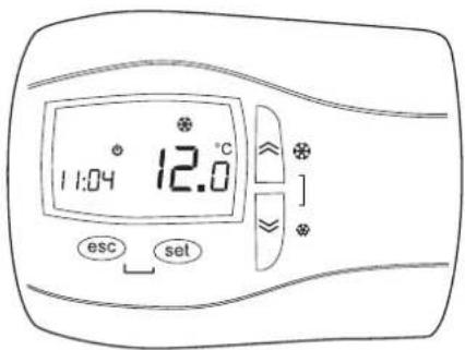
Remoto control
Suitable for wall mounting, it reports all the functions available on the user interface placed on the unit.
The buttons, functions associated with the buttons and the display indications are the same as those provided for the standard interface.
All configuration and control operations are further facilitated by the double display which allows the name and value of the selected parameter to be shown at the same time.
Refer to the enclosed manual for the installation and connection procedures and operating instructions.
CONTROL SYSTEM
Menu structure
The control system provides for three menus with tree structure.
| Menu Access procedure Sub menu | Parameters | Available functions | |||
| Operating mode | Press ESC button for long (ESC button associated function) | Stby | - | Operating mode change | |
| HERt | |||||
| COOL | |||||
| Status | Press SET button (SET button direct function) | A1 | R,01 | Display input AI1 | |
| R,02 | Display input AI2 | ||||
| R,03 | Display input AI3 | ||||
| R,04 | Display input AI4 | ||||
| d1 | d,01 | Display input ID1 | |||
| d,02 | Display input ID2 | ||||
| d,03 | Display input ID3 | ||||
| d,04 | Display input ID4 | ||||
| d,05 | Display input ID5 | ||||
| AO | AO1 | Display output AO1 | |||
| AO2 | Display output AO2 | ||||
| AO3 | Display output AO3 | ||||
| d0 | d001 | Display output DO1 | |||
| d002 | Display output DO2 | ||||
| d003 | Display output DO3 | ||||
| d004 | Display output DO4 | ||||
| d005 | Display output DO5 | ||||
| CL | HOUr | Clock adjustment : time | |||
| dATE | Clock adjustment : date | ||||
| YEAR | Clock adjustment : year | ||||
| AL | - | Display active alarms | |||
| SP | HERt | Set point display and setting : heating | |||
| COOL | Set point display and setting : cooling | ||||
| Sr | HERt | Display real set point : heating | |||
| COOL | Display real set point : cooling | ||||
| Hr | CPO1 | Display compressor operating hours | |||
| PUD1 | Display pump operating hours | ||||
| Programming | Press ESC + SET buttons at the same time (combined functioni ESC + SET buttons) | PRr | CF | CF 19 | Remote stand by enable |
| CF20 | Remote Cooling-Heating enable | ||||
| CF63 | Device address (Modbus protocol) | ||||
| CF66 | Display parameter map code | ||||
| CF67 | Display parameter map revision | ||||
| tr | tr01 | Heat pump enable | |||
| tr17 | Heat pump lock set point | ||||
| PI | PI 05 | Modulating pump speed : cooling | |||
| PI 11 | Modulating pump speed : heating | ||||
| H, H,02 | Integrative electrical heaters enable | ||||
| FnC EUR | Alarm memory reset | ||||
| EU | - | Alarm memory display | |||
To go from one level to the level below press the SET button. To return to the upper level press the ESC button. To scroll the menu up and down inside the same level, press respectively the UP and DOWN buttons.
To modify the value of the selected parameter press the UP and DOWN buttons. Press the SET button to confirm the new value. Press the ESC button not to confirm the new value.
CONTROL SYSTEM
Inputs and outputs
In order to control the unit, the controller is equipped with the following inputs and outputs :
All the inputs and outputs are connected to the wiring board except for output AO2 which directly controls a relay inside the electrical panel of the unit and output AO3 which directly control the modulating pump.
Controller technical data
| Description | Typical | Minimum | Maximum |
| Power supply voltage * | 12,0 V~ | 10,8 V~ | 13,2 V~ |
| Power supply frequency | 50 Hz / 60 Hz | - | - |
| Power | 5 VA | - | - |
| Insulation class | 2 | - | - |
| Protection degree | Frontale IP0 | - | - |
| Ambient operating temperature | 25 °C | -10 °C | 60 °C |
| Ambient operating humidity (not condensing) | 30 % | 10 % | 90 % |
| Ambient storage temperature | 25 °C | -20 °C | 85 °C |
| Ambient storage humidity (not condensing) | 30 % | 10 % | 90 % |
* The controller is powered by a proper insulated transformer mounted on the wiring board.
CONTROL SYSTEM
Alarms
Alarm activation and reset
The controller can perform a complete diagnosis of the unit, detecting all the operating faults and reporting a set of alarms. Activation of an alarm involves :
- locking of the loads concerned
- reporting of the alarm code on the display (in case of simultaneous alarms the one with the lowest index is displayed whereas the complete list of active alarms can be shown by accessing the “Status \ AL” menu)
- recording of the event in the alarms memory
Alarms that can damage the unit or the plant require a manual reset that implies an action by the operator to reset the controller (pressing the UP and DOWN buttons at the same time). It is recommended to carefully check the cause of the alarm and make sure the problem is eliminated before restarting the unit. In any case the unit restarts only if the cause of the alarm has disappeared.
Less critical alarms are automatically reset. As soon as the cause of the alarm is eliminated the unit starts working again and the alarm code disappears from the display. Some of these alarms require a manual reset if the number of events per hour exceeds a fixed limit.
Pressing any button it's possible to deactivate the alarm : alarm report disappears from the display, the alarm LED starts flashing and the Alarm digital output is disabled. The deactivation of the alarm does not affect the alarm in progress.
Number of events per hour
For some alarms the number of events per hour is recorded: if, in the last hour, the number of events reaches a fixed limit, the alarm reset change from automatic to manual.
Sampling of alarms occurs every 112 seconds. If an alarm is activated several times in a sampling period (112 seconds) it is counted only once.
Esempio. If the fixed limit of events per hour is 3, in order to change from automatic to manual reset, tha alarm has to remain active for a period of time between 2*112 seconds and 3*112 seconds.

bar_stacked
| Phase | Value | | -------------- | ----- | | Manual reset | 1 | | Counter | 1 | | Manual reset | 2 | | Manual reset | 3 | | Manual reset | 112 s | | Manual reset | 112 s | | Manual reset | 112 s | | Manual reset | 112 t | | Manual reset | 112 t | | Manual reset | 112 t | | Manual reset | 112 t | | Manual reset | 112 t | | Manual reset | 112 t | | Manual reset | 112 t | | Manual reset | 112 t | | Manual reset | 112 t | | Manual reset | 112 t |Alarms memory
The controller enables the recording of the alarms occurred during the unit operation (up to a maximum 99 events). The following informations are recorded for each event :
- alarm code
- activation time
- activation date
- deactivation time
- deactivation date
- type of alarm (automatic or manual reset)
Such informations can be shown by accessing the "Programming \ EU" menu.
When the number of events recorded is higher than 99 the following events are recorded overwriting the oldest alarms.
The alarms memory can be cancelled by means of the Eur function available inside the "Programming \FnC" menu, keeping pressed the SET button till YES appears on the display.
CONTROL SYSTEM
Alarms table
| Locked loads | ||||||||
| Compressor | Antifreeze heater 1st step | Pump | Integrative heaters 2nd step | Fans | ||||
| CODE ALARM RESET | (1) | INPUT DO2 | DO4 DO5 | AO3 AO1 | ||||
| Er05 | Low pressurePhase presence and sequence controllerSoft starter alarm | A / M ID2 | X X | |||||
| Er20 | Differential pressure switch A / M ID3 X | X X | (2) | X | X | |||
| Er30 | Antifreeze M AI2 X X | |||||||
| Er41 | High pressure / Fan thermal protection A / M ID1 X X | |||||||
| Er45 | Clock fault A - | |||||||
| Er46 | Clock to be adjusted A - | |||||||
| Er47 | Communication error with remote control | A - | ||||||
| Er60 | Water inlet probe fault | A | AI1 X X X | X X | ||||
| Er61 | Water outlet probe fault | A | AI2 | X | X | X | X | X |
| Er62 | Liquid line probe fault | A | AI3 | |||||
| Er68 | Outdoor air probe fault | A | AI4 | |||||
| Er75 | Liquid pressure transducer fault | A | AI3 | |||||
| Er80 | Configuration error | A - | X X X X | X | ||||
Notes:
(1) A = automatic reset, M = manual reset
(2) Only when the alarm change to manual reset
E-05 Low pressure – Phase presence and sequence controller - Soft starter alarm
The alarm becomes manual reset when the number of operations per hour is higher than the set value of the parameter AL01.
The alarm is bypassed for the time equal to the value defined by parameter AL02 starting from the activation of the compressor or of the reversing valve.
The alarm is disabled during defrost.
Er20 Differential pressure switch
The alarm is activated if the associated digital input remains activated for at least 2 seconds and automatically resets if the digital input remains not activated for at least 2 seconds. The alarm change to manual reset if the digital input remains activated for more than 10 seconds.
The start-up from stand-by mode of operation to cool or heat provides the by-pass of 'alarm for 30 seconds after the activation of the pump with the compressor off.
Er-30 Antifreeze
The alarm is bypassed for 3 minutes from switching on of the unit (in heating mode only).
Er41 High pressure / Fan thermal protection
The alarm change to manual reset when the number of events per hour is more than the value set in parameter AL03.
Er62 Liquid line probe fault
When the alarm is activated the fans work with on-off logic according to compressor request. The defrost cycle inlet and outlet are managed according to the operating time of the compressor.
Er-68 Outdoor air probe fault
When the alarm is activated, neither climate control nor dynamic defrost are available.
E-75 Liquid pressure transducer fault
When the alarm is activated the fans work with on-off logic according to compressor request. The defrost cycle inlet and outlet are managed according to the operating time of the compressor.
CONTROL SYSTEM
Functions available for the user
Operating mode selection
It's possible to select the operating mode by accessing the "Operating mode" menu:
- Cooling COOL
- Heating HERE
- STAND BY * 5tdby
* The antifreeze function is still active.
Remote STAND BY
This function allows remote selection of the STANDBY mode. If the input is activated (open contact) the controller is in STANDBY mode and the operating mode can not be modified from the user interface.
The digital input used is DI4. Set the parameter [F\ 19 = -27] to enable this function.
Remote Cooling-Heating
This function allows remote selection of Cooling or Heating mode. If the input is activated (open contact) the unit is in heating mode. If the input is not activated (closed contact) the unit is in cooling mode. The operating mode can not be modified from the user interface (but STAND BY mode can be selected).
The digital input used is DI5. To enable this function set the parameter CF20 = 14.
Set point
The set point value in cooling (COOL) and heating (HERE) can be set by accessing the "SERAUS \ SP" menu. These values must be between a fixed maximum and minimum value. The purpose of the controller is to keep the water temperature at the unit inlet as close as possible to the set value, by activating the compressor according to an on-off logic.
Operating in heat pump mode
For all the heat pump units the parameter tr01 enables operation in heat pump mode when its value is 1. It is possible to set an outdoor air temperature value (parameter tr17) below which heat pump mode is locked (in any case the integrative electrical heaters, if present, remain activated).
Antifreeze
The plate heat exchanger is protected by the activation of an electrical antifreeze heater and the activation of the antifreeze alarm, occurring in sequence when the temperature of the water at the exchanger outlet reaches dangerous values. The buffer tank is protected by the antifreeze heater (accessory) activated together with the plate heat exchanger heater.
When the outdoor air temperature approaches 0irc C, if the unit is not working, the pump is activated in any case to prevent excessive cooling of the water in the pipes.
Integrative electrical heaters
The parameter H102 enables the electrical heaters, as integration of the heat pump, when its value is 1. The heaters are activated according to a two step logic depending on the unit inlet water temperature. When present, the heaters also carry out the storage tank antifreeze function.
Dynamic defrost
The activation limit is modified in a dynamic way according to the outdoor air temperature.
Serial communication
The device is configured to communicate on a serial line using the MODBUS protocol. When the device is connected, it must be assigned an address univocally identifying it among all the devices connected to the same serial line ("Modbus individual address"). This address must be between 1 and 247 and is configurable by means of the parameter [F63] (see section on serial communication).
Operating hours recording
The controller can record the operating hours of compressor and pump. Access the "SEREUS \Hr" menu to see the values. The hours are reset by pressing the SET button for long, while the hours of operation are displayed.
Power failure
In case of a power failure, when the power is restored the controller will return to the status before the power failure. If a defost cycle was in progress the procedure is cancelled. All safety timing in progress are cancelled and reinitialized.
Clock
The controller is equipped with an internal clock to record date and time of each alarm occurred during unit operation (see "Alarms memory"). The clock can be set by accessing the "SEAEUS \CL" menu.
Modulating pump management
Modifying the parameters PI 05 (for cooling mode) and PI I I (for heating mode). It is possible to set the rotational speed of the modulating pump in order to get the water flow rate required to maintain the desired temperature difference between the water inlet and outlet. Verify that the value set ensures a flow of water within the operating limits specified in the installation manual and use.
CONTROL SYSTEM
Serial communication
The unit can communicate on a serial line using the Modbus communication protocol with RTU coding.
The unit can be connected to an RS485 network by means of the serial interface supplied as an accessory, and reply to the requests of any master device connected to the network.
Serial line settings
The serial line must be set as follows :
- baud rate
- data bits : 8
- stop bits : 1
• parity : even
All the devices connected to the same serial line MUST use the same settings.
Device address
To communicate properly, each device connected to the serial network must have an univocal address ("Modbus individual address") contained between 1 and 247. This address can be set by modifying the parameter [F63].
Modbus commands
The Modbus commands implemented by the controller are :
• parameter reading 3 (Hex 03 : Read Holding Registers)
• parameter writing 16 (Hex 10 : Write Multiple Registers)
Addresses table
All the available resources are stored in the controller as WORD (2 byte) and therefore require the reading or writing of an entire Modbus register. According to the Modbus protocol, to identify a register of address X the address X-1 must appear in the message. Some registers contain more than one piece of information: in this case the bits representing the resource value are identified by means of the number of bits used ("Bit number") and by the least significant bit ("Lsb"). In the writing operation for these registers it is necessary to read the current register value, modify the bits representing the resource concerned and rewrite the entire register.
Example.
Bit number = 4 Lsb = 7 Resource value = 3
1 5 amp; 1 4 amp; 1 3 amp; 1 2 amp; 1 1 amp; 1 0 amp; 9 amp; 8 amp; 7 amp; 6 amp; 5 amp; 4 amp; 3 amp; 2 amp; 1 amp; 0 0 amp; 1 amp; 1 amp; 0 amp; 1 amp; 0 amp; 0 amp; 1 amp; 1 amp; 1 amp; 0 amp; 1 amp; 1 amp; 0 amp; 1 amp; 0
The resources can be only read (R), only written (W) or read and written (RW).
To interpret the value written in the register it is necessary to consider the value of CPL, EXP and UM :
CPL : if the register represents a number with sign (CPL = Y) carry out the following conversion :
0 = register value lt; 3 2 7 6 7: resource value = register value 3 2 7 6 8 = register value lt; 6 5 5 3 5: resource value = register value - 6 5 5 3 6
EXP : indicates the exponent of the power of 10 to be multiplied by the register value to obtain the resource value.
| EXP | Moltiplicatore | |
| -2 | 10-2 | 0,01 |
| -1 | 10-1 | 0,1 |
| 0 | 100 | 1 |
| 1 | 101 | 10 |
| 2 | 102 | 100 |
MU : indicates the unit of measure of the resource
IMPORTANT. DO NOT modify any parameter not indicated in the table provided or indicated as a read only parameter (R), otherwise the warranty will be invalidated.
CONTROL SYSTEM
| Label Description RW | Register address | Bit number | Lsb CPL EXP UM | ||||||
| Dec Hex | |||||||||
| COOL Set point cooling RW 16900 4204 16 0 Y -1 °C | |||||||||
| HERE Set point heating RW 16902 4206 16 0 Y -1 °C | |||||||||
| CF 19 | Remote stand by enable | RW | 49303 | C097 | 8 | 0 | Y | 0 | - |
| CF20 | Remote Cooling-Heating enable | RW | 49304 | C098 | 8 | 0 | Y | 0 | - |
| CF63 | Device serial address | RW | 49178 | C01A | 8 | 0 | N | 0 | - |
| Er01 | Heat pump enable | RW | 49665 | C201 | 8 | 0 | N | 0 | - |
| Er17 | Heat pump lock set point | RW | 16930 | 4222 | 16 | 0 | Y | -1 | °C |
| PI 05 | Modulating pump speed : cooling | RW | 49749 | C255 | 8 | 0 | N | 0 | % |
| PI 11 | Modulating pump speed : heating | RW | 49757 | C25D | 8 | 0 | N | 0 | % |
| H 02 | Integrative electrical heaters enable | RW | 49858 | C2C2 | 8 | 0 | N | 0 | - |
| CP01 | Compressor operating hours | R | 753 | 02F1 | 16 | 0 | N | 0 | ore |
| PUO1 | Pump operating hours | R | 763 | 02FB | 16 | 0 | N | 0 | ore |
| RI 01 | Water inlet probe | R | 344 | 0158 | 16 | 0 | Y | -1 | °C |
| RI 02 | Water outlet probe | R | 346 | 015A | 16 | 0 | Y | -1 | °C |
| RI 03 | Liquid line probe | R | 348 | 015C | 16 | 0 | Y | -1 | °C/BAR |
| RI 04 | Outdoor air probe | R | 350 | 015E | 16 | 0 | Y | -1 | °C |
| - | Unit operating in COOLING | R | 33028 | 8104 | 1 | 4 | N | 0 | - |
| - | Unit operating in HEATING | R | 33028 | 8104 | 1 | 6 | N | 0 | - |
| - | Unit in STAND BY (user interface or serial communication) | R | 33028 | 8104 | 1 | 2 | N | 0 | - |
| - | Unit in STAND BY (digital input) | R | 33028 | 8104 | 1 | 3 | N | 0 | - |
| - | Unit in OFF | R | 33028 | 8104 | 1 | 0 | N | 0 | - |
| - | COOLING mode enable * | W | 33471 | 82BF | 1 | 3 | N | 0 | - |
| - | HEATING mode enable * | W | 33471 | 82BF | 1 | 4 | N | 0 | - |
| - | STAND BY enable * | W | 33471 | 82BF | 1 | 5 | N | 0 | - |
| - | Unit switching on (1 = ON ; 0 = OFF ) | W | 33471 | 82BF | 1 | 7 | N | 0 | - |
| - Alarm Er-05 R 33037 810D 1 5 N 0 - | |||||||||
| - | Alarm Er-20 | R | 33039 | 810F | 1 | 4 | N | 0 | - |
| - | Alarm Er-30 | R | 33040 | 8110 | 1 | 6 | N | 0 | - |
| - | Alarm Er-41 | R | 33042 | 8112 | 1 | 1 | N | 0 | - |
| - | Alarm Er-45 | R | 33042 | 8112 | 1 | 5 | N | 0 | - |
| - | Alarm Er-46 | R | 33042 | 8112 | 1 | 6 | N | 0 | - |
| - | Alarm Er-60 | R | 33044 | 8114 | 1 | 4 | N | 0 | - |
| - | Alarm Er-61 | R | 33044 | 8114 | 1 | 5 | N | 0 | - |
| - | Alarm Er-62 | R | 33044 | 8114 | 1 | 6 | N | 0 | - |
| - | Alarm Er-68 | R | 33045 | 8115 | 1 | 4 | N | 0 | - |
| - | Alarm Er-75 | R | 33046 | 8116 | 1 | 3 | N | 0 | - |
* If several operation modes are enabled by mistake :
- OFF has priority over STAND BY, HEATING, COOLING
- STAND BY has priority over HEATING, COOLING
- HEATING has priority over COOLING
Probes characteristics
The temperature probes used are NTC 10K (10 kΩ at 25°C).
When the probe bulb is at the temperature of 25irc C the electrical resistance measurable at the probe ends is 10 k Ω .
The thermistor of these probes has a negative temperature coefficient: the electrical resistance value decreases as the temperature increases.
To find out if a temperature probe is faulty or disconnected, check the correspondence between the resistance value in kΩ and the bulb temperature in °C according to the table.
For a reliable verify it is not necessary to check all the single values but is enough to check some random values. If the instrument indicates neverending resistance then the probe is interrupted.
| Temperature | Resistance |
| [°C] | [kΩ] |
| 0 | 25,7950 |
| 5 | 21,3963 |
| 10 | 17,7477 |
| 15 | 14,7213 |
| 20 | 12,2110 |
| 25 | 10,1287 |
| 30 | 8,4015 |
| 35 | 6,9688 |
| 40 | 5,7805 |
| 45 | 4,7948 |
| 50 | 3,9771 |
| 55 | 3,2989 |
INVERTER
The display is accessible from the external of the unit dismounting the frontal panel of the electrical box. (ref. fig.1). The unit can be equipped with n° 1 for each pump (part. 1-fig.2) and/or with n° 1 for each fan (part. 2-fig.2).

Operating setting procedure
To access the Delta VFD-EL settings:
- Ensure the inverter is in STOP mode by pressing
- Press MODE until the message appears

- To enter int the Frd menu press

- At this point, we are in the main parameters menu.
-To access and modify the parameters, choose the parameter, press ENTER, change value with the arrows keys and confirm with
- The modified parameter will be confirmed with the label

- At the end of the parameters settings, turn OFF and turn ON power supply, then check that the RUN light is on and the STOP light is flashing.
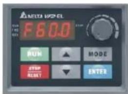
Fig.3
Alarm
Note that the intervention of the inverter alarm stops the inverter and so stops the device controlled by the inverter with the result of generating alarms on the main electronic controller: i.e. the alarm of the water pump inverter generates the water pump thermal switch alarm.
| Code | Input on inverter | Alarm Cause Troubleshooting | |
| oc | U-V-W Over current | Abnormal increase in current | 1. Check if motor power corresponds with the AC motor drive output power2. Check the wiring connections to U/T1, V/T2, W/T3 for possible short circuits3. Check the wiring connections between the AC motor drive and motor for possible short circuits, also to ground4. Check for loose contacts between AC motor drive and motor5. Increase the Acceleration Time6. Check for possible excessive loading conditions at the motor7. If there are still any abnormal conditions when operating the AC motor drive after a shortcircuit is removed and the other points above are checked, it should be sent back to manufacturer |
| oU | - Over voltage | The DC bus voltage has exceeded its maximum allowable value | 1. Check if the input voltage falls within the rated AC motor drive input voltage range2. Check for possible voltage transients3. DC-bus over-voltage may also be caused by motor regeneration. Either increase the Decel. Time or add an optional brake resistor (and brake unit)4. Check whether the required braking power is within the specified limits |
INVERTER
| Code | Input on inverter | Alarm Cause Troubleshooting | |
| oH I | - Overheating | Heat sink temperature too high | 1. Ensure that the ambient temperature falls within the specified temperature range2. Make sure that the ventilation holes are not obstructed3. Remove any foreign objects from the heatsinks and check for possible dirty heat sink fins4. Check the fan and clean it5. Provide enough spacing for adequate ventilation |
| oH2 | - Overheating | Heat sink temperature too high | 1. Ensure that the ambient temperature falls within the specified temperature range2. Make sure that the ventilation holes are not obstructed3. Remove any foreign objects from the heatsinks and check for possible dirty heat sink fins4. Check the fan and clean it5. Provide enough spacing for adequate ventilation |
| LU | - Low voltage | The AC motor drive detects the the DC bus voltage has fallen below its minimum value | 1. Check whether the input voltage falls within the AC motor drive rated input voltage range2. Check for abnormal load in motor3. Check for correct wiring of input power to R-ST (for 3-phase models) without phase loss |
| oL | - Overload | The AC motor drive detects excessive drive output current | 1. Check whether the motor is overloaded2. Reduce torque compensation setting in Pr.07.023. Use the next higher power AC motor drive model |
| oL I | - Overload 1 | Internal electronic overload trip | 1. Check for possible motor overload2. Check electronic thermal overload setting3. Use a higher power motor4. Reduce the current level so that the drive output current does not exceed the value set by the Motor Rated Current Pr.07.00 |
| oL2 | - Overload 2 Motor overload | 1. Reduce the motor load2. Adjust the over-torque detection setting to an appropriate setting (Pr.06.03 to Pr.06.05) | |
| HPF I | - | CC (Current clamp) | Internal error Return to factory |
| HPF2 | - | OV hardware error | Internal error Return to factory |
| HPF3 | - | GFF hardware error | Internal error Return to factory |
| HPF4 | - | OC hardware error | Internal error Return to factory |
| bb | - | External base block | External base block |
| ocR | - | Over-current during acceleration | Over-current during acceleration |
| acd | - | Over-current during deceleration | Over-current during deceleration |
| ocn | - | Over-current during constant speed operation | Over-current during constant speed operation |
| EF | - External fault External fault | 1. When multi-function input terminals (MI3-MI9) are set to external fault, the AC motor drive stops output U, V and W2. Give RESET command after fault has been cleared | |
INVERTER
| Code | Input on inverter | Alarm Cause Troubleshooting | ||
| cF 1.0 | - | Internal EEPROM can not be programmed | Internal error Return to factory | |
| cF 1.1 | - | Internal EEPROM can not be programmed | Internal error Return to factory | |
| cF2.0 | - | Internal EEPROM can not be read | Internal error | 1. Press RESET key to set all parameters to factory setting2. Return to the factory |
| cF2.1 | - | Internal EEPROM can not be read | Internal error | 1. Press RESET key to set all parameters to factory setting2. Return to the factory |
| cF3.0 | -U-phase error Internal error Return to factory | |||
| cF3.1 | -V-phase error Internal error Return to factory | |||
| cF3.2 | -W-phase error Internal error Return to factory | |||
| cF3.3 | -OV or LV Internal error Return to factory | |||
| cF3.4 | - | Temperature sensor error | Internal error Return to factory | |
| cF3.5 | - | Temperature sensor error | Internal error Return to factory | |
| OFF | -Ground fault Ground fault | When (one of) the output terminal(s) is grounded, short circuit current is more than 50% of AC motor drive rated current, the AC motor drive power module may be damagedNOTE: The short circuit protection is provided for AC motor drive protection, not for protection of the user1. Check whether the IGBT power module is damaged2. Check for possible poor insulation at the output line | ||
| cFR | - | Auto accel/decel failure | Auto accel/ decel failure | 1. Check if the motor is suitable for operation by AC motor drive2. Check if the regenerative energy is too large3. Load may have changed suddenly |
| cE-- | - | Communication error | No communication | 1. Check the RS485 connection between the AC motor drive and RS485 master for loose wires and wiring to correct pins2. Check if the communication protocol, address, transmission speed, etc. are properly set3. Use the correct checksum calculation4. Please refer to group 9 in the chapter 5 for detail information |
| codE | - | Software protection failure | Internal error Return to factory | |
| AErr | AVI-ACM | Analog signal error | No signal on ACI | Check the wiring of ACI |
| FbE | AVI-ACM | PID feedback signal error | No signal on ACI | 1. Check parameter settings (Pr.10.01) and AVI/ACI wiring2. Check for possible fault between system response time and the PID feedback signal detection time (Pr.10.08) |
| PHL | - | Phase loss | Loss of a input phase | Check input phase wiring for loose contacts |
| AUE | - | Auto tuning error | Auto tuning feature failure | 1. Check cabling between drive and motor2. Retry again |
| CP 10 | - | Communication time-out error on the control board or power board | Communication time-out | 1. Press RESET key to set all parameters to factory setting2. Return to the factory |
| PLC 1 | - | Motor overheat protection | Possible motor overheat | 1. Check if the motor is overheat2. Check Pr.07.12 to Pr.07.17 settings |
| PLC2 | - | Motor overheat protection | Possible motor overheat | 1. Check if the motor is overheat2. Check Pr.07.12 to Pr.07.17 settings |
START UP
Start up
The following operations must be carried out only by properly trained personnel. To make the contractual warranty effective, start up must be carried out by authorized service centres.
Before calling the service centre it is advisable to make sure that all the installation steps have been completed (positioning, electrical connections, hydraulic connections).
Preliminary operation
WARNING - Before you perform the checks listed below, please read carefully the section "Safety and Maintenance"
Verify that :
- the unit has not suffered visible damages due to transport or positioning
- the unit is placed on an horizontal surface able to bear its weight
- the minimum operating area are respected
- the ambient conditions comply with the provided operating limits
- the hydraulic and electrical connections has been carried out correctly
Electrical cheks
Verify that the unit power supply line complies with the regulations in force. Check that the section of power cables are suitable to withstand the overall absorption of the unit (see electrical data), and that the unit has been properly grounded.
Check that all electrical connections are well fixed and all terminals properly tightened.
Switch on the unit by turning the switch in position ON. The display will light a few seconds after power up, check the operating status of both Std-by or off (via keyboard). A wrong sequence of the power supply phases is immediately detected by the phase sequence controller (standard on all the three phase power supply units) and reported on the display of the unit. To eliminate the error switch each other two phases of the power supply line.
Verify that:
- the voltage of the power supply line complies with the nominal one of the unit
- for three phase power supply units, the unbalance between the phases is lower than 3% (a higher value produces an excessive current input on one or more phases causing possible damages to the electrical components of the unit)
NOTE. Example of phase unbalance calculation
- Read the value of the three line voltages using a voltmeter :
| line voltage between phases L | 1 and L2 : V- | 1-2 = 390 V |
| line voltage between phases L | 2 and L3 : V | 2-3 = 397 V |
| line voltage between phases L | 3 and L1 : V | 3-1 = 395 V |
- Calculate the difference between the maximum and minimum value of the measured line voltages :
ΔV = (V1-2;V2-3;V3-1) - (V1-2;V2-3;V3-1) = V2-3 - V1-2 = 397 - 390 = 7V
- Calculate the average line voltage value :
Δ_ average = (V _ 1 - 2 + V _ 2 - 3 + V _ 3 - 1) / 3 = (3 9 0 + 3 9 7 + 3 9 5) / 3 = 3 9 4 V
- Calculate the percentage unbalance value :
ΔV _ / V _ average × 100 = 7 / 394 × 100 = 1,78 % lt; 2 %
Check that the connections made by the installer comply with the data reported here.
If present, check that the resistance of the compressors oil crankase are operating, by measuring the temperature rise of the oil crankase. The resistance / s must be in operation for at least 24 hours before starting the compressor , and in each case the temperature of the oil crankase must be 10 - 15 °C higher than the ambient temperature .
WARNING - At least 24 hours prior to the operation of the unit (or at the end of each period of prolonged pause) the unit must be powered in such a way as to allow the heating elements of the compressor crankcases to evaporate the refrigerant present in the oil. Failure to do so may cause serious damage to the compressor and will void the warranty.
Hydraulic circuit checks
Check that all hydraulic connections are executed correctly: Refer to the installation manual.
Check that the hydraulic system is filled, under pressure and air free (possibly vent it).
Make sure that any shutoff valves present in the system are properly open. Make sure that the circulation pump is running and that the water flow is sufficient to close the contact of the differential pressure and / or flow switches.
Check the correct operation of the differential pressure and / or flow
switches: close the shutoff valve at the outlet of the heat exchanger, the unit display must show the alarm message, eventually reopen the valve and reset the alarm.
Turning on
ATTENTION. The operation must be agreed in advance depending on the timing of construction of the plant. Before the intervention of Service Department all works (electrical and plumbing connections, water filling and air vent of the plant) will have been completed.
Start all the plant components necessary to guarantee an adequate water flow rate on the plant hydraulic circuit.
Activate the unit in cooling or in heating mode operating on the user interface and setting a set point suitable to require the unit to work.
Refrigerant circuit checks
The vibrations during transport, may have loose connections: check for leaks of refrigerant gas especially at the refrigerant pressure taps, pressure transducers and pressure switches.
After a short period of operation, check the oil level of the compressor (if present siight oil) and the absence of bubbles in the glass of liquid indicator (if present). The continuous passage of vapor bubbles may mean that the refrigerant charge is low or that the expansion valve is not properly adjusted. The presence of bubbles in the running for short periods, however, is possible.
Evaporation and condensation temperature
Verify that:
- the saturation temperature (dew point) corresponding to the condensing pressure is about 10-15°C higher than the outdoor air temperature in cooling and about 5°C higher than the water outlet temperature in heating
- the saturation temperature (dew point) corresponding to the evaporating pressure is about 5°C lower than the water outlet temperature in cooling and about 5-10°C lower than the outdoor air temperature in heating
Superheat
Check the superheat comparing the temperature measured with a contact thermostat fitted to the compressor suction pipe, with the temperature shown on the low pressure gauge (saturation temperature corresponding to the evaporation pressure). The difference between these two temperatures gives the value of the superheta. The optimal values are between 4 and 8 °C.
Subcooling
Check the subcooling comparing the temperature measured with a contact thermostat on the pipe outlet of the condenser, with the temperature shown on the pressure gauge of high pressure (saturation temperature corresponding to the condensation pressure). The difference between these two temperatures gives the value of subcooling. The optimal values are between 4 and 5ircC , for reversible units with subcooler in the coil the optimal values are between 10 and 20ircC depending on the external air temperature.
Discharge temperature
If the values of subcooling and superheat are regular, the temperature measured at the outlet of the compressor discharge pipe must be:
- Units charged with R410A of 30/40 °C higher than the condensing temperature
- Units charged with R134a of 15/20 °C higher than the condensing temperature.
Hydraulic circuit check
- the difference between the water inlet and outlet temperature from the plate heat exchanger of the unit is inside the limits provided.
Electrical setting check
- the current absorbed by the compresor and the fans is lower than the maximum value admitted (FLA), as indicated in the section "Technical data and performances"
SAFETY AND MAINTENANCE
Basic safety rules
Recall that the use of products that use electricity and water entails the observance of some basic safety rules, such as: This appliance is not intended for use by persons (including children) with reduced physical, sensory or mental capabilities or lack of experience and knowledge, unless supervised or instructed on the use of the appliance by a person responsible for their safety. Children should be supervised to ensure that they do not play with the appliance.
It is forbidden to any technical intervention or maintenance without first disconnecting the unit from the mains supply by moving the master switch and the main control panel to "Off".
You may not modify safety equipment or settings.
Do not pull, detach or twist the electrical cables coming from the unit even if it is disconnected from the mains supply.
It is forbidden to leave containers of flammable substances near the unit.
Do not touch the appliance when barefoot or with wet or damp parts of the body.
It is forbidden to open the doors of access to the internal parts of the unit without first ensuring that the system switch to "Off".
Not dispose of, abandon or leave within reach of children packaging materials as it can be a potential source of danger.
IMPORTANT SAFETY INFORMATION
There is no guarantee proper operation as a result of a fire, before restarting the machine, contact an authorized service center. If equipped with safety valves refrigerant, in case of excessive pressure the safety valves can discharge high temperature refrigerant gas to the atmosphere. Wind, earthquakes and other natural phenomena of exceptional intensity were not considered. When using the unit in an aggressive atmosphere and or with aggressive water consult the factory.
Residual Risks
The machine has been designed with a view to reducing the risks to persons and the environment in which it is installed, to the minimum. To eliminate residual risks, it is therefore advisable to become as familiar as possible with the machine in order to avoid accidents that could cause injuries to persons and/or damage to property.
a. Access to the unit
Only qualified persons who are familiar with this type of machine and who are equipped with the necessary safety protections (footwear, gloves, helmet, etc.) may be allowed to access the machine. Moreover, in order to operate, these persons must have been authorized by the owner of the machine and be recognized by the actual Manufacturer.
b. Elements of risk
The machine has been designed and built so as not to create any condition of risk. However, residual risks are impossible to eliminate during the designing phase and are therefore listed in the following table along with the instructions about how to neutralize them.
| Part in question Residue hazard Mode Precautions | |||
| Compressor and delivery pipe | Burns | Contact with the pipes and/or compressor | Avoid contact by wearing protective gloves |
| Delivery pipes, heat recovery exchanger and coils | Explosion Excessive pressure | Turn off the machine, check the high pressure switch and safety valve, the fans and condenser | |
| Pipes in general Ice burns | Leaking refrigerant Do not pull on the pipes | ||
| Electrical cables, metal parts | Electrocution, serious burns | Defective cable insulation, live metal parts | Adequate electrical protection (cor-rectly ground the unit) |
| Heat exchange coils | Cuts | Contact | Wear protective gloves |
| Fans | Cuts Contact with the skin | Do not push the hands or objects through the fan grille | |
Disconnection and disposal
The machine contains lubricating oil and refrigerant gas for which, during the destruction of the unit, these fluids will be recovered and disposed of in accordance with the rules in force in the country where it is installed.
During the disconnection thus avoid spills or leaks of refrigerant gas and of the plant water if treated with additives or antifreeze substances.
The machine must not be abandoned in the process of destruction, but it can also be stored outdoors with gas, water and electrical circuits intact and closed.
For dismissing and disposal, deliver the units to specialized centres according to your national laws.
SAFETY AND MAINTENANCE
General recommendations about the R410A refrigerant used
1 SUPPLIER COMPANY AND PRODUCT IDENTIFICATION
Card No. FRIG 8
Product
R-410A
Supplier company identification RIVOIRA SpA
2 COMPOSITION / INFORMATION ON INGREDIENTS
Substance / Preparation Preparation
Components / Impurities Contains the following components :
Difluoromethane (R32) 50 % in weight
Pentafluoroethane (R125) 50 % in weight
EEC No. Non-applicable for mixtures
Trade-name / /
3 IDENTIFICATION OF HAZARDS
Identification of hazards Liquefied gas.
The vapours are heavier than air and can cause suffocation, reducing the oxygen available for breathing.
Rapid evaporation of the fluid can cause freezing.
Can cause cardiac arrhythmia.
4 FIRST-AID MEASURES
Inhalation Do not administer anything if the person has fainted.
Take the person outdoors. Use oxygen or artificial respiration if necessary.
Do not administer adrenaline or similar substances.
Contact with eyes Rinse thoroughly with plenty of water for at least 15 minutes and see a doctor.
Contact with skin Wash immediately with plenty of water. Immediately remove all contaminated garments.
Swallowing
5 FIRE-PREVENTION MEASURES
Specific hazards
Increase in pressure.
Dangerous fumes Halogen acids, traces of carbonyl halides.
Fire-extinguishing means usable
All the known fire-extinguishing means can be used.
Specific methods
Cool the containers/tanks with water sprays.
Special protection equipment
Use self-contained breathing apparatus in confined spaces.
6 MEASURES AGAINST ACCIDENTAL SPILLING OF THE PRODUCT
Personal protection
Evacuate personnel to safe areas. Provide for adequate ventilation. Use personal protection equipment
Protection for the environment
It evaporates.
Product removal methods
It evaporates.
7 HANDLING AND STORAGE
Handling and storage
Ensure an adequate air change and/or extraction in the workplaces. Only use well-ventilated rooms. Do not breathe vapours or aerosols. Carefully close the containers and keep them in a cool, dry and well-ventilated place. Keep in the original containers.
Incompatible products
Explosives, flammable materials, organic peroxides.
8 CONTROL OF EXPOSURE / PERSONAL PROTECTION
Personal protection
Ensure adequate ventilation, especially in closed areas.
Control parameters
Difluoromethane (R32): Recommended exposure limits: AEL (8h and 12h TWA) = 1000 ml/m3
Pentafluoroethane (R125): Recommended exposure limits: AEL (8h and 12h TWA) = 1000 ml/m3
Respiratory tract protection
For rescue and for maintenance works in tanks, use self-contained breathing apparatus. The vapours are heavier than air and can cause suffocation, reducing the oxygen available for breathing.
Eye protection
Total protection glasses.
Hand protection
Rubber gloves.
Hygiene measures
Do not smoke.
9 CHEMICAL-PHYSICAL PROPERTIES
Relative density, gas (air=1)
Heavier than air.
Solubility in water (mg/l)
Not known, but deemed very low.
Appearance
Colourless liquefied gas.
Odour
Similar to ether.
Fire point
Does not ignite.
10 STABILITY AND REACTIVITY
Stability and reactivity
No decomposition if used according to the special instructions.
Materials to be avoided
Alkali metals, alkali-earth metals, granulated metal salts, Al, Zn, Be, etc. in powder.
Hazardous products of decomposition
Halogen acids, traces of carbonyl halides.
11 TOXICOLOGICAL INFORMATION
Local effects
Concentrations substantially above the value TLV (1000 ppm) can cause narcotic effects. Inhalation of highly concentrated products of decomposition can cause respiratory insufficiency (pulmonary oedema).
Long-term toxicity No carcinogenic, teratogenic or mutagenic effects have been recorded in experiments on animals.
Specific effects
Rapid evaporation of the fluid can cause freezing. Can cause cardiac arrhythmia.
12 ECOLOGICAL INFORMATION
Effects linked to ecotoxicity
Pentafluoroethane (R125)
Potential global warming with halocarbides; HGWP (R-11 = 1) = 0.84
Potential impoverishment of the ozone; ODP (R-11 = 1) = 0
SAFETY AND MAINTENANCE
13 CONSIDERATIONS ON DISPOSAL
General Do not dispose of where accumulation can be hazardous.
Usable with reconditioning.
The depressurised containers must be returned to the supplier.
Contact the supplier if instructions for use are deemed necessary.
14 INFORMATION FOR TRANSPORT
Designation for transport LIQUEFIED GAS N.A.S.
( DIFLUOROMETHANE, PENTAFLUOROETHANE )
UN No. 3163
Class/Div
2.2
ADR /RID No. 2, 2nd A
ADR/RID hazard no. 20
ADR label Label 2 : non-toxic non-flammable gas.
CEFIC Groupcard 20g39 - A
Other information for transport Avoid transport on vehicles where the loading zone is not separate from the cab.
Make sure the driver is informed about the potential risk of the load and knows what to do in case of
accident or emergency
Before starting transport, make sure the load is properly secured and :
make sure the valve of the container is closed and does not leak;
make sure the blind cap of the valve (when provided) is correctly fitted;
make sure the cap (when provided) is correctly fitted and that there is an adequate ventilation passage;
ensure compliance with the current provisions.
15 INFORMATION ON REGULATIONS
The product must not be labelled according to Directive 1999/45/EC.
Comply with the regulations given below, and the relevant applicable updates and amendments.
Circulars no. 46/79 and 61/81 of the Ministry of Labour : Risks related to the use of products containing aromatic amines
Leg. Decree no. 133/92 : Regulations on the discharge of hazardous substances in waters
Leg. Decree no. 277/91 : Protection of workers against noise, lead and asbestos
Law 256/74, Decree 28/1/92, Leg. Decree no. 52 dated 3/2/97, Decree dated 28/4/97 as amended : Classification, packing and labelling of hazardous substances and preparations
Decree no. 175/88, as amended : Activities with significant accident risks (Seveso Law)
Decree no. 203/88 : Emissions into the atmosphere
Decree no. 303/56 : Work hygiene
Decree no. 547/55 : Regulations on accident prevention
Leg. Decree no.152 dated 11/5/99 : Protection of waters
16 OTHER INFORMATION
Recommended uses Refrigerant
Can cause suffocation in high concentration.
Keep in a well-ventilated place.
Do not breathe the gas.
The risk of suffocation is often underestimated and must be clearly explained during the training of operators.
Ensure compliance with all the national and regional regulations.
Before using this product in any new process or trial, an in-depth study on safety and compatibility of the product with the materials must be carried out.
The above information is based on our current know-how and describes the product according to the safety requirements. It does not however represent a guarantee and assurance of the qualities in a legal sense. Each person responds personally for compliance with such regulations.
First aid
- Move the victim away from the toxic source, keep him warm and allow him to rest.
- Administer oxygen if necessary.
• Proceed with artificial respiration if necessary.
- Give heart massage in the case of heart failure.
- Immediately seek medical help.
Contact with the skin:
- Immediately thaw the affected parts under running lukewarm water.
- Remove contaminated clothing (garments may stick to the skin in the case of ice burns) if they have not adhered to the skin.
- Seek medical assistance if necessary.
Contact with the eyes:
- Immediately rinse the eyes with physiologic eyewash or clean water for at least 10 minutes with the eyelids pulled open.
- Seek medical assistance if necessary.
Swallowing:
- Do not make the victim vomit. If the victim is conscious, have him rinse his mouth out with clean water and then drink 200, 300 ml of water.
- Immediately seek medical help.
- Do not administer adrenaline or sympathomimetic drugs after exposure owing to the risk of cardiac arrhythmia.
For further information about the characteristics of the refrigerant, consult the technical briefs that can be obtained from manufacturers of refrigerant products.
SAFETY AND MAINTENANCE
General Rules for Maintenance
The maintenance is extremely important for the functioning of the system and the regular working of the unit over time.
In accordance with the European Regulation EC 303/2008, it should be noted that companies and engineers in maintenance, repair, leak testing and recovery / recycle refrigerant gases should be CERTIFIED in accordance with local regulations.
Maintenance must be performed in compliance with the safety rules and tips given in the manual supplied with the unit.
Routine maintenance helps maintain unit efficiency, reduce the rate of deterioration which each device is subject in time and gather information and data to understand the efficiency of the unit and prevent failures.
For extraordinary maintenance or in case you need service, contact only to a specialized service center approved by the manufacturer and use original spare parts.
In accordance with the European Regulation EC 1516/2007 it is necessary to prepare a “equipment record”.
Provide anyway a databook (not supplied) that allows you to keep track of interventions made on the unit; in this way it will be easier to properly program the various interventions and will facilitate a possible troubleshooting.
Bring on the databook : date, type of intervention made, description of the intervention , measurements , reported anomalies , alarms recorded in the alarm history , etc. ...
Routine maintenance
The inspections described below, to which the unit must be subjected, do not require specific technical know-how.
They merely include a few simple inspections involving certain parts of the unit.
The table below gives a recommended list of inspections which should be carried out at the indicated intervals.
Provide controls and interventions more frequently in case of heavy (continuous or intermittent high, close to operating limits, etc ...) or critical (essential service such as data centres, hospital etc ...) use.
| DESCRIPTION WEEKLY MONTHLY EVERY SIX MONTHS | ||
| Visual inspection of the unit • | ||
| Inspection of hydraulic circuit • | ||
| Inspection of electrical system • | ||
| Inspection of condensing system • | ||
| Inspection of the water heat exchanger • | ||
| Inspection of the water filter • | ||
| Inspection of the water pumps (if present) • | ||
| Reading and adjustment of the operating parameters • |
- Visual inspection of the structure of the unit
When checking the condition of the parts that form the structure of the unit, pay particular attention to the parts liable to rust.
If traces of rust are noted, they must be treated with rust-inhibitor paint in order to eliminate or reduce the problem.
Check to make sure that the external panels of the unit are well fixed.
Bad fixing gives rise to noise and abnormal vibrations.
• Inspection of hydraulic circuit
Check visually to make sure that there are no leaks in the hydraulic circuit. Check that water filters are clean.
• Inspection of electrical system
Make sure that power cables that supply the unit are not torn, cracked or damaged in a way that could impair its insulation.
- Inspection of the ventilated condensing/evaporating section
WARNING: The finned pack exchanger has fins made of aluminium or some other thin material, thus even accidental contact could cause cuts.
Condensing/Evaporating coils
In view of the function of this component, it is very important for the surface of the exchanger to be as free as possible from clogging caused by items that could reduce the fan's air flow rate and, thus, the performances of the unit itself.
The following operations may be required:
- Remove all impurities (such as paper scraps, leaves, etc.) that could be clogging the surface of the bank either by hand or using a brush (comply with the above mentioned safety prescriptions).
- If the dirt has deposited on the fins and is difficult to remove by hand, use a flow of compressed air or pressurized water on the aluminium surface of the coils, remembering to direct the flow in a vertical and opposite to the standard flow direction to prevent the fins from being damaged.
- "Comb" the coils with the relative tool, using the appropriate comb spacing for the fins if some parts of them are bent or squashed.
SAFETY AND MAINTENANCE
Axial fans
Visually inspect these parts to make sure that the fans are well fixed to the bearing grille and that this latter is fixed to the structure of the unit. Check the fan bearings, and close the terminal box and cable glands. Bearings damaged and bad fixing are the source of abnormal noise and vibrations,
• Inspection of the water heat exchangers
The exchangers must ensure the maximum heat transfer possible so keep them clean and free from dirt that may reduce efficiency; make sure that the temperature difference between water outlet temperature and evaporation/condensation does not increase over time, if the difference exceeds 8 -10 °C it is necessary to proceed cleaning the water side of the exchanger, keeping in mind the following: water circulation must be in the opposite direction than normal, the fluid velocity does not exceed 1.5 times the nominal velocity and use just water or moderately acid products but only water for final washing.
• Inspection of the water filters
Make sure to clean the filter and remove any impurities that block the proper flow of water, contributing to increase pressure drop and therefore energy consumption of the pumps. Refer to the section “Hydraulic Connections” too.
• Inspection of the water pumps
Check water leakages, the state of the bearings, the closing of the terminal box and integrity of the cable. Bearings damaged and bad fixing are the source of abnormal noise and vibrations,
- Reading and adjustment of the operating parameters
This control can be done using the pressure gauges (if installed) of the refrigerant circuits and using the pressure and temperature gauges (if installed) of the hydraulic circuits of the unit (evaporator + heat recovery - if present)
NOTE: FOR THE PLANT WATER FILL AND DRAIN REFER TO THE SECTION HYDRAULIC CONNECTIONS
CAUTION
As a result of extraordinary maintenance on the cooling circuit with component replacement, before restarting the machine, perform the following steps:
- Pay attention to restore the refrigerant charge indicated on the name plate of the machine.
- Open all the ball valves in the refrigerant circuit.
- Correctly connect the power supply and grounding.
- Check the hydraulic connections.
- Check that the water pump is working properly.
- Clean water filters.
- Check that the finned coils are not dirty or clogged.
- Check the proper rotation of fans.
The manufacturer declines all responsibility for any inaccuracies in this manual due to printing or typing errors. The reserves the right to modify the products contents in this catalogue without previous notice.

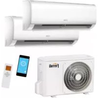
- CE
- TABLE OF CONTENTS
- GENERAL FEATURES 4
- ACCESSORIES AND OPTIONAL EQUIPMENT....8
- TECHNICAL DATA AND PERFORMANCE - BASE VERSION (VB) 10
- BR-BP UNIT....15
- NOISE LEVELS....16
- ELECTRICAL DATA 17
- OPERATING LIMITS....18
- WATER PRESSURE DROP 19
- WORKING HEAD. 20
- DIMENSIONAL AND PHYSICAL DATA 22
- RECEPTION AND POSITIONING....24
- HYDRAULIC CONNECTIONS....25
- ELECTRICAL CONNECTIONS....27
- R410A PROTECTION DEVICES....28
- REFRIGERANT FLOW DIAGRAM 29
- CONTROL SYSTEM 30
- INVERTER....39
- START UP 42
- SAFETY AND MAINTENANCE....43
- GENERAL FEATURES
- General specifications
- Declaration of conformity
- Unit dataplate
- Unit description
- Unit identification code
- Description of components
- Control system
- Versions
- ACCESSORIES AND OPTIONAL EQUIPMENT
- Options
- Hydraulic scheme
- Accessories
- NOTES
- TECHNICAL DATA AND PERFORMANCE - BASE VERSION (VB)
- COOLING performances
- HEATING performances
- BR - BP UNIT
- Corrective factors
- NOISE LEVELS
- Reference conditions
- ELECTRICAL DATA
- OPERATING LIMITS
- BRINE UNIT BR - BP
- DIMENSIONAL AND PHYSICAL DATA
- Minimum operating area
- RECEPTION AND POSITIONING
- Receiving
- Check on receiving
- Safety instructions
- Handling
- Storing
- Packaging removal
- Positioning
- HYDRAULIC CONNECTIONS
- General rules
- Protection devices
- Tips for a successful installation
- ATTENTION
- Water component for corrosion limit
- Precautions for the Winter
- Air vent and water drain
- Maximum volume of water in the system with wet module
- Electrical connections
- Power supply system
- Unit power supply
- Upstream protection
- Connections available for the user
- General alarm
- Remote stand by
- Remote Cooling-Heating
- Remote control
- Pump control
- R410A PROTECTION DEVICES
- REFRIGERANT FLOW DIAGRAM
- Display
- Remoto control
- Menu structure
- Inputs and outputs
- Alarms
- Alarm activation and reset
- Number of events per hour
- Alarms memory
- Functions available for the user
- Operating mode selection
- Set point
- Operating in heat pump mode
- Antifreeze
- Integrative electrical heaters
- Dynamic defrost
- Serial communication
- Operating hours recording
- Power failure
- Clock
- Modulating pump management
- Serial line settings
- Device address
- Modbus commands
- Addresses table
- Probes characteristics
- INVERTER
- Operating setting procedure
- Alarm
- START UP
- Preliminary operation
- WARNING - Before you perform the checks listed below, please read carefully the section "Safety and Maintenance"
- Verify that :
- Electrical cheks
- Verify that:
- NOTE. Example of phase unbalance calculation
- Hydraulic circuit checks
- Turning on
- Refrigerant circuit checks
- Evaporation and condensation temperature
- Superheat
- Subcooling
- Discharge temperature
- Hydraulic circuit check
- Electrical setting check
- SAFETY AND MAINTENANCE
- Basic safety rules
- IMPORTANT SAFETY INFORMATION
- Residual Risks
- a. Access to the unit
- b. Elements of risk
- Disconnection and disposal
- General recommendations about the R410A refrigerant used
- SUPPLIER COMPANY AND PRODUCT IDENTIFICATION
- COMPOSITION / INFORMATION ON INGREDIENTS
- IDENTIFICATION OF HAZARDS
- FIRST-AID MEASURES
- FIRE-PREVENTION MEASURES
- MEASURES AGAINST ACCIDENTAL SPILLING OF THE PRODUCT
- HANDLING AND STORAGE
- CONTROL OF EXPOSURE / PERSONAL PROTECTION
- CHEMICAL-PHYSICAL PROPERTIES
- STABILITY AND REACTIVITY
- TOXICOLOGICAL INFORMATION
- ECOLOGICAL INFORMATION
- CONSIDERATIONS ON DISPOSAL
- INFORMATION FOR TRANSPORT
- INFORMATION ON REGULATIONS
- OTHER INFORMATION
- First aid
- General Rules for Maintenance
- Routine maintenance
- - Visual inspection of the structure of the unit
- • Inspection of hydraulic circuit
- • Inspection of electrical system
- - Inspection of the ventilated condensing/evaporating section
- Condensing/Evaporating coils
- Axial fans
- • Inspection of the water heat exchangers
- • Inspection of the water filters
- • Inspection of the water pumps
- - Reading and adjustment of the operating parameters
- NOTE: FOR THE PLANT WATER FILL AND DRAIN REFER TO THE SECTION HYDRAULIC CONNECTIONS
- CAUTION
Brand : FERROLI
Model : RMA2 He
Category : Air Conditioning