
TP3 COND 65÷1000 - Boiler FERROLI - Free user manual and instructions
Find the device manual for free TP3 COND 65÷1000 FERROLI in PDF.

| Product type | Condensing boiler, TP3 COND series |
| Brand | Ferroli |
| Fuel | Gas (G20) or oil (diesel) |
| Nominal thermal output | From 61.3 kW (model 65) to 935 kW (model 1000) depending on fuel |
| Useful efficiency (80/60 °C) | Up to 98.8% (gas, model 1000) |
| Useful efficiency (50/30 °C) | Up to 107% (gas) or 104% (diesel) |
| Seasonal energy efficiency class | A |
| NOx class | 4 or 5 (gas), 1 or 3 (diesel) depending on model |
| Dimensions (L x W x H) model 65 | 700 x 1437 x 1157 mm (A x B x C) |
| Dimensions (L x W x H) model 1000 | 1180 x 1424 x 2760 mm (A x B x C) |
| Empty weight | From 377 kg (model 65) to 2150 kg (model 1000) |
| Power supply | 230 V / 50 Hz, single phase |
| Electrical protection | IPX0D |
| Max service pressure | 6 bar |
| Max heating temperature | 95 °C |
| Heating circuit water capacity | From 237 L (model 65) to 1565 L (model 1000) |
| Hydraulic connections | Flow and return DN 125 (models 820-1000); drain 1"1/2 |
| Flue connection | Diameter 350 mm (models 820-1000) |
| Construction | 3 flue passes, submerged cylindrical combustion chamber, tubular bundle with turbulators |
| Maintenance | Annual cleaning of tubes, combustion chamber and flue box; condensate check |
| Safety | Safety thermostat, pressure switch, safety valve, anti-freeze system (6 °C) |
| Use | Central heating, indoor installation, connection to expansion vessel |
Frequently Asked Questions - TP3 COND 65÷1000 FERROLI
User questions about TP3 COND 65÷1000 FERROLI
0 question about this device. Answer the ones you know or ask your own.
Ask a new question about this device
Download the instructions for your Boiler in PDF format for free! Find your manual TP3 COND 65÷1000 - FERROLI and take your electronic device back in hand. On this page are published all the documents necessary for the use of your device. TP3 COND 65÷1000 by FERROLI.
USER MANUAL TP3 COND 65÷1000 FERROLI
natural_image
Three Ferroli industrial cooling units with mounting flanges, shown in 3D rendering (no text or symbols on the units themselves)CE
IT ANUALE PER L'INSTALLAZIONE, L'USO E LA MANUTENZIONE
ES ANUAL DE INSTALACIÓN, USO Y MANTENIMIENTO
EN INSTALLATION, USE AND MAINTENANCE MANUAL
FR OTICE POUR L'INSTALLATION, L'UTILISATION ET L'ENTRETIEN
natural_image
Technical schematic of a mechanical device with internal flow arrows indicating material movement (no text or symbols)fig. 3 - Da modello TP3 COND 65 a TP3 COND 230
natural_image
Technical line drawing of a mechanical device with mounting flanges and a labeled component (A), no text or symbols present.fig. 4 - Da modello TP3 COND 370 a TP3 COND 1000
natural_image
Technical line drawing of a mechanical lift or pallet jack with wheels and structural supports (no text or symbols)natural_image
Technical line drawing of a mechanical device with a vertical column and control panel (no text or symbols)fig. 7
fig. 10
natural_image
Technical line drawing of a mechanical housing with circular components and labeled parts (A), no readable text or symbols present.fig. 11 fig. 12

natural_image
Technical line drawing of a mechanical assembly with labeled component A (no text or symbols beyond label)fig. 13
natural_image
Technical line drawing of a mechanical assembly with no visible text or symbolsfig. 14
natural_image
Simple line drawing of a mechanical component with curved lines and a circular base (no text or symbols)fig. 18
Legenda
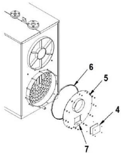
fig. 20 fig. 21
natural_image
Cross-sectional diagram of a mechanical device with internal flow arrows indicating material movement (no text or symbols)fig. 3 - De modelo TP3 COND 65 a TP3 COND 230
natural_image
Technical line drawing of a mechanical enclosure with mounting flanges and a labeled component (no text or symbols present)fig. 4 - De modelo TP3 COND 370 a TP3 COND 1000
natural_image
Technical line drawing of a mechanical lift or pallet jack assembly (no text or symbols)natural_image
Technical line drawing of an industrial machine with a tall chimney and control panel (no text or symbols)fig. 7
natural_image
Technical line drawing of a mechanical device with two circular components and labeled parts (A), showing internal structure without any text or symbols.fig. 11 fig. 12

natural_image
Technical line drawing of a mechanical assembly with labeled component A (no text or symbols beyond label)fig. 13
natural_image
Technical line drawing of a mechanical assembly with two views: one showing a bolted joint and the other showing a curved pipe connection (no text or symbols present)fig. 14
natural_image
Simple line drawing of a mechanical component with curved lines and a base (no text or symbols)fig. 18
Leyenda
1 Bulbo termostato 1a etapa
2 Bulbo termostato 2a etapa
3 Bulbo termostato de seguridad
4 Sonda de temperatura
IMPORTANTE
SI SE DECIDE INSTALAR OTRO TIPO DE TERMORREGULACIÓN, SE DEBE UTILIZAR E INSTALAR, COMO SE INDICÓ ANTE- RIORMENTE, UN TERMOSTATO DE SEGURIDAD CONFORME A LA NORMATIVA VIGENTE, CON TEMPERATURA DE DISPARO (SWITCHING POINT) = 110-6°C.
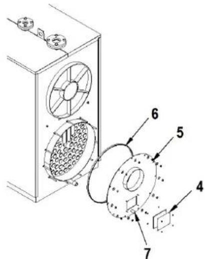
fig. 20 fig. 21
-
General instructions 49
-
Certifications 49
-
Introduction 50
-
Technical, constructive and dimensional characteristics....50
4.1 Description of unit 50
4.2 Working principle 50
4.3 Technical data - Dimensions - Hydraulic connections 51
4.4 Identification....59
- Installation 59
5.1 Packing....59
5.2 Handling....59
5.3 Installation room 60
5.4 Discharge of combustion products 61
5.5 Plumbing connections....61
5.6 Front door opening and adjustment....63
5.7 Burner assembly 64
5.8 Flame control sight glass connection- 64
5.9 Probe and bulb positioning 65
-
Schematic diagram - System for heating and domestic hot water 66
-
Startup....67
7.1 Preliminary checks....67
7.2 First ignition 67
7.3 Boiler shutdown 67
- Maintenance 67
8.1 General rules 67
8.2 Routine maintenance....67
8.3 Extraordinary maintenance....67
8.4 Boiler cleaning 68
8.5 Boiler operation check 68
8.6 Burner operation check....69
8.7 Troubleshooting 69
1. GENERAL INSTRUCTIONS
- The instruction manual is an integral part of the product and provides a description of everything that must be followed during installation, use and maintenance.
- This unit must only be used for its intended purpose.
- This unit is designed to heat water to a temperature below boiling point at atmospheric pressure and must be connected to a heating system compatible with its performance, characteristics and heat output.
- Before installation, make sure the boiler has not been damaged during handling and transport.
• Installation must be carried out by suitably qualified personnel, in accordance with current regulations. - Disconnect the unit from the power supply before carrying out any cleaning or maintenance.
- FERROLI declines any liability for damage to persons and/or property due to incorrect installation, adjustment and maintenance, and improper use.
- Startup of the boiler and related system must be carried out by authorized personnel.
- First startup is for checking that all the control and adjustment devices work properly.
- Long periods of non-use of the unit require the intervention of qualified personnel.
- The unit and its accessories must be disposed of appropriately, in conformity with the current regulations.
Regulations
The installer must ensure compliance with local and current regulations regarding: the place where the boiler is installed, the required ventilation conditions; perfect tightness of the connection and flue; the fuel and electrical system connections, and any other provisions regarding safety.
Warranty conditions
The validity of the warranty is subject to compliance with the rules and recommendations on use contained in this manual. Any non-compliance or modification will void the warranty. The warranty does not cover damage due to corrosion from the acidic condensate of combustion products or as a result of encrustations caused by the use of hard or aggressive water, such damage being attributable solely to operation of the system.
2. CERTIFICATIONS

The CE marking certifies that the products meet the essential requirements of the applicable directives.
The declaration of conformity may be requested from the manufacturer.
PRODUCT IDENTIFICATION CODES
| OIL / GAS | |
| TP3 COND 65 0RGZ3AXA | |
| TP3 COND 100 0RGZ4AXA | |
| TP3 COND 150 0RGZ5AXA | |
| TP3 COND 230 0RGZ8AXA | |
| TP3 COND 370 0RGZBAXA | |
| TP3 COND 500 0RGZDAXA | |
| TP3 COND 650 0RGZGAXA | |
| TP3 COND 820 0RGE01XA | |
| TP3 COND 1000 0RGF02XA | |
COUNTRIES OF DESTINATION: IT
3. INTRODUCTION
Dear Customer,
Thank you for choosing a TP3 COND boiler. This manual has been prepared in order to provide instructions and advice on the installation, proper use and maintenance of the boiler.
Please read it carefully and keep it for further consultation. Carefully follow the instructions provided, to ensure the best use of this high quality product. Failure to comply with that given in this manual exonerates the Manufacturer from any liability and voids the warranty.
4. TECHNICAL, CONSTRUCTIVE AND DIMENSIONAL CHARACTERISTICS
4.1 Description of unit
The type of construction of TP3 COND series boilers ensures high performance and high efficiency with low fume temperatures, resulting in reduced pollutant emissions.
The main technical elements of the design are:
- Careful study of the geometries, to obtain an optimum combination of combustion volumes and exchange surfaces.
• The choice of materials used, to ensure long service life.
These boilers feature pressurized combustion, with triple gas pass, double overlaid cladding and firebox totally wet at the top and tube bundle at the bottom, holding the turbulators that create a swirling path, increasing the heat exchange by convection. At the tube bundle outlet the fumes are collected in the rear chamber and conveyed to the flue. The boilers have a hinged door for right or left opening, adjustable in height and depth. The shell is insulated with a thick glass wool mat and covered with an additional layer of tear-resistant material.
The exterior finish consists of painted steel panels. Lifting hooks are located on top of the boilers.
The boilers have two 1/2" attachments for bulb holder sheaths (suitable for holding 3 bulbs each).
The pre-wired control panel (to be ordered separately) will be placed in the special housing in the boiler shell and allows automatic operation of the boiler.
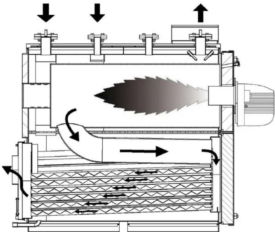
4.2 Working principle
TP3 COND boilers have a totally wet blind cylindrical firebox in which the first gas pass is developed, a larger firebox return tube (2nd pass) and a tube bundle at the bottom (3rd pass). At the tube bundle outlet the fumes are collected in the rear smoke chamber and conveyed to the flue. The combustion chamber is always pressurized when the burner is working. For the value of this pressure, see the table on pag. 52 at "Fume side pressure losses". The flue and flue connection must comply with the current Standards and Legislation, using rigid pipes that are resistant to heat, condensate and mechanical stresses, and be tight (fig. 1).
natural_image
Cross-sectional diagram of a mechanical device showing internal flow and heat transfer (no text or labels)fig. 1 - Working principle
4.3 Technical data - Dimensions - Hydraulic connections
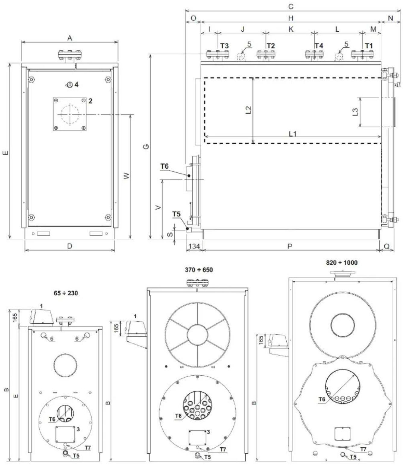
fig. 2 - Dimensions and connections
Legend
1 Instrument panel
2 Burner connection flange
3 Smoke chamber cleaning door
4 Flame control sight glass
5 Lifting hooks
6 Holes for lifting hook
T1 Heating delivery
T2 High temperature return
T3 Low temperature return
T4 Expansion vessel connection
T5 Boiler discharge connection
T6 Flue connection
T7 Condensate discharge connection
4.3.1 Table of technical data, dimensions and connections
The column on the right gives the abbreviation used on the data plate.
| TP3 COND 65 100 150 230 370 500 650 | ||||||||||||||||
| Gas category I2H (IT - ES) | ||||||||||||||||
| Pmax | Pmin | Pmax | Pmin | Pmax | Pmin | Pmax | Pmin | Pmax | Pmin | Pmax | Pmin | |||||
| Heat input (kW) . 61.3 18.4 94.3 28.3 141.5 42.5 217.0 65.1 349.1 | 104.7 47 | 1.7 141 | 5 613.2 | 184 Qr | (Hi) | |||||||||||
| Effective rated output (80/60°C) (kW) | 59.5 | 18.0 | 91.5 | 27.7 | 137.3 | 41.6 | 210.5 | 63.8 | 338.6 | 102.6 | 457.5 | 138.7 | 594.8 | 180.3 | P 80° - 60° | |
| Effective rated output (50/30°C) (kW) | Gas | 65 | 19.7 | 100 | 30.3 | 150 | 45.4 | 230 | 69.7 | 370 | 112 | 500 | 151.4 | 650 | 196.8 | P 50° - 30° |
| Oil | 62.9 | 19.1 | 96.7 | 29.4 | 145 | 44.2 | 222.4 | 67.7 | 357.8 | 108.9 | 483.5 | 147.2 | 628.5 | 191.3 | P 50° - 30° | |
| Efficiency (80/60°C) (%) | 97.2 | 98 | 97.0 | 98 | 97.7 | 98 | 97.9 | 98 | 98.2 | 98 | 98.4 | 98 | 98.5 | 98 | ||
| Efficiency (50/30°C) (%) | Gas | 106 | 107 | 106 | 107 | 106 | 107 | 106 | 107 | 106 | 107 | 106 | 107 | 106 | 107 | |
| Oil | 102.5 | 104 102 | 5 104 | 102.5 104 | 102.5 | 104 102 | 5 104 | 102.5 104 | 102.5 104 | |||||||
| Efficiency 30% | Gas | 107.5 | 107.5 | 107.5 | 107.5 | 107.5 | 107.5 | 107.5 | ||||||||
| Oil | 104.5 | 104.5 | 104.5 | 104.5 | 104.5 | 104.5 | 104.5 | |||||||||
| NOx class | Gas | 4 | 4 | 5 | 5 | 5 | 4 | 4 | NOx | |||||||
| Oil | 3 | 1 | 1 | 1 | 1 | 1 | 1 | NOx | ||||||||
| Fuel consumption Max. output | Gas (G20) m3/h | 6.46 | 9.98 | 14.97 | 22.96 | 36.94 | 49.92 | 64.9 | ||||||||
| Oil kg/h | 5.17 | 7.95 | 11.93 | 18.3 | 29.43 | 39.77 | 51.7 | |||||||||
| Max. working pressure bar | 6 | 6 | 6 | 6 | 6 | 6 | 6 | PMW | ||||||||
| Max. heating temperature °C | 95 | 95 | 95 | 95 | 95 | 95 | 95 | tmáx | ||||||||
| Heating water content liters | 237 | 296 | 349 | 571 | 881 | 1202 | 1327 | |||||||||
| Pressure loss on fume side mbar | 0.4 0.65 | 1.7 1.7 | 2 | 3.5 4.2 | ||||||||||||
| Pressure loss on water side with Δt=10°C KPa | 0.15 | 0.2 | 3.0 | 3.4 | 2.4 | 2.6 | 3.2 | |||||||||
| Pressure loss on water side with Δt=20°C KPa | 0.07 | 0.13 | 1.7 | 1.3 | 1.8 | 0.8 | 0.9 | |||||||||
| Pmax | Pmin | Pmax | Pmin | Pmax | Pmin | Pmax | Pmin | Pmax | Pmin | Pmax | Pmin | |||||
| Flue gas temp. (80/60) | Gas °C | 73 | 62 | 82 | 61 | 78 | 56 | 79 | 59 | 75 | 60 | 73 | 58 | 71 | 57 | |
| Oil °C | 76 | 61 | 75 | 61 | 76 | 54 | 81 | 57 | 75 | 58 | 75 | 56 | 74 | 55 | ||
| Flue gas temp. (50/30) | Gas °C | 54 | 34 | 66 | 36 | 54 | 37 | 52 | 33 | 54 | 34 | 52 | 32 | 50 | 31 | |
| Oil °C | 50 | 34 | 53 | 36 | 53 | 36 | 55 | 32 | 55 | 32 | 52 | 33 | 48 | 33 | ||
| Fume flow rate | Gas Kg/h | 93.3 28.0 | 143.5 | 43.1 215 | 3 64.7 | 330.2 99 | 9.1 531 | 2 159.2 | 716.8 215 | 93.3 31 280.0 | ||||||
| Oil Kg/h | 91.8 | 27.6 | 141.2 | 42.4 | 211.9 | 63.6 | 324.9 | 97.5 | 522.7 | 156.8 | 705.4 | 211.9 | 918.2 | 275.5 | ||
| Fume flow rate | Gas g/s | 26 | 8 | 40 | 12 | 60 | 18 | 92 | 28 | 148 | 44 | 199 | 60 | 259 | 78 | |
| Oil g/s | 25 | 8 | 39 | 12 | 59 | 18 | 90 | 27 | 145 | 44 | 196 | 59 | 255 | 77 | ||
| CO2 | Gas % | 0.1 10.1 | 10.1 10.1 | 10.1 10.1 | 10.1 10.1 | 10.1 10.1 | 10.1 10.1 | 10.1 10.1 | 10.1 10.1 | 10.1 10.1 | ||||||
| Oil % | 3.3 13.3 | 13.3 13.3 | 13.3 13.3 | 13.3 13.3 | 13.3 13.3 | 13.3 13.3 | 13.3 13.3 | 13.3 13.3 | 13.3 13.3 | |||||||
| Protection rating | IPXOD | |||||||||||||||
| Electrical power supply V/Hz | 230/50 | 230/50 | 230/50 | 230/50 | 230/50 | 230/50 | 230/50 | |||||||||
| Empty weight kg | 377 | 436 | 490 | 645 | 1035 | 1338 | 1451 | |||||||||
| Sizes | A mm | 700 | 700 | 700 | 800 | 950 | 1050 | 1050 | ||||||||
| B mm | 1437 | 1437 | 1437 | 1637 | 1462 | 1462 | 1462 | |||||||||
| C mm | 1157 | 1377 | 1577 | 1777 | 1987 | 2187 | 2387 | |||||||||
| D mm | 650 | 650 | 650 | 750 | 900 | 1000 | 1000 | |||||||||
| E mm | 1275 | 1275 | 1275 | 1475 | 1655 | 1805 | 1805 | |||||||||
| G mm | 1335 | 1335 | 1335 | 1535 | 1715 | 1860 | 1860 | |||||||||
| H mm | 878 | 1098 | 1298 | 1498 | 1698 | 1900 | 2100 | |||||||||
| I mm | 123 123 123 123 123 123 123 123 123 123 123 123 123 123 123 123 123 123 123 123 123 123 123 123 123 123 | |||||||||||||||
| J mm | 200 260 350 400 450 500 500 | |||||||||||||||
| K mm | 200 300 320 400 450 500 500 | |||||||||||||||
| L mm | 200 260 350 400 450 500 500 | |||||||||||||||
| M mm | 155 155 155 156 176 221 221 | |||||||||||||||
| N mm | 157 157 157 157 167 167 167 | |||||||||||||||
| O mm | 122 122 122 122 122 122 122 122 122 122 122 122 122 122 122 122 122 122 122 122 122 122 122 122 122 122 | |||||||||||||||
| P mm | 846 | 1066 | 1266 | 1467 | 1667 | 1867 | 2067 | |||||||||
| Q mm | 134 134 134 134 134 134 134 134 134 134 134 134 134 134 134 134 134 134 134 134 134 134 134 134 134 134 | |||||||||||||||
| S mm | 70 | 70 | 70 | 70 | 60 | 60 | 60 | |||||||||
| V mm | 450 443 435 500 550 587 580 | |||||||||||||||
| W mm | 905 | 905 | 905 | 1055 | 1200 | 1315 | 1315 | |||||||||
| Firebox internal diameter L2 ∅ mm 420 420 420 500 550 610 610 | ||||||||||||||||
| Firebox length L1 mm 686 906 1106 1308 1473 1672 1872 | ||||||||||||||||
| Nozzle max. diameter L3 ∅ mm 155 155 155 190 190 190 190 190 190 190 190 190 190 190 190 190 190 190 190 190 190 190 190 190 190 190 190 190 19 | ||||||||||||||||
| Nozzle min. length mm 160 160 160 160 160 160 160 160 160 160 160 160 160 160 160 160 160 160 160 160 160 160 160 160 160 16 | ||||||||||||||||
| Heating delivery T1 DN 50 DN 50 DN 50 DN 50 DN 50 DN 50 DN 50 DN 50 DN 50 DN 50 DN 50 DN 50 DN 50 DN 50 DN 50 DN 50 DN 50 DN 50 DN 50 DN 50 DN 50 DN 50 DN 50 DN 50 DN 50 DN 5 | ||||||||||||||||
| High temperature heating return T2 DN 40 DN 40 DN 40 DN 40 DN 40 DN 40 DN 40 DN 40 DN 40 DN 40 DN 40 DN 40 DN 40 DN 40 DN 40 DN 40 DN 40 DN 40 DN 40 DN 40 DN 40 DN 40 DN 40 DN 40 DN 40 DN 4 | ||||||||||||||||
| TP3 COND 820 1000 | ||||||
| Gas category | ||||||
| Pmax Pmin Pmax | Pmin | |||||
| Heat input (kW) . 767 498 935 608 Qn (Hi) | ||||||
| Effective rated output (80/60°C) (kW) 752 489 916 595 P 80° - 60° | ||||||
| Effective rated output (50/30°C) (kW) | Gas 820 533 1000 650 P 50° - 30° | |||||
| Oil 793.5 516.7 967.7 630 P 50° - 30° | ||||||
| Efficiency (80/60°C) (%) 98.7 98.2 98.8 97.8 | ||||||
| Efficiency (50/30°C) (%) | Gas 106 107 106 107 | |||||
| Oil 102.5 104 102.5 104 | ||||||
| Efficiency 30% | Gas 107.5 107.5 | |||||
| Oil | 104.5 104.5 | |||||
| NOx class | Gas | 5 | 5 | NOx | ||
| Oil | 1 | 1 | NOx | |||
| Fuel consumption Max. output | Gas (G20) m3/h | 81.2 | 99 | |||
| Oil kg/h | 64.7 78.8 | |||||
| Max. working pressure | bar | 6 | 6 | PMW | ||
| Max. heating temperature | °C | 95 | 95 | tmáx | ||
| Heating water content | liters | 1450 | 1565 | |||
| Pressure loss on fume side | mbar | 6 | 6.4 | |||
| Pmax Pmin Pmax | Pmin | |||||
| Flue gas temp. (80/60) | Gas °C | 72 | 58 | 73 | 62 | |
| Oil °C | 753 | 57 | 75 | 63 | ||
| Flue gas temp. (50/30) | Gas °C | 50 | 32 | 50 | 33 | |
| Oil °C | 51 | 33 | 51 | 33 | ||
| Fume flow rate | Gas Kg/h | 1176 | 764 | 1434 | 932 | |
| Oil Kg/h | 1172 | 761 | 1428 | 929 | ||
| Fume flow rate | Gas g/s $27 | 213 398 259 | ||||
| Oil g/s | 325 | 211 | 396 | 257 | ||
| CO2 | Gas % | 10 | 10 | 10 | 10 | |
| Oil % | 13 | 13 | 13 | 13 | ||
| Protection rating | IPXOD | |||||
| Electrical power supply V/Hz | 230/50 | 230/50 | ||||
| Empty weight kg | 2050 | 2150 | ||||
| Sizes | A mm | 1180 | 1180 | |||
| B mm | 1424 | 1424 | ||||
| C mm | 2620 | 2760 | ||||
| D mm | 1120 | 1120 | ||||
| E mm | 2006 | 2006 | ||||
| G mm | 2075 | 2075 | ||||
| H mm | 2094 | 2244 | ||||
| I mm | 224 | 224 | ||||
| J mm | 650 | 650 | ||||
| K mm | 300 | 450 | ||||
| L mm | 600 | 600 | ||||
| M mm | 320 | 320 | ||||
| N mm | 278 2783 | |||||
| O mm | 262 | 262 | ||||
| P mm | 2068 | 2216 | ||||
| Q mm | 226 | 226 | ||||
| S mm | 78 | 78 | ||||
| V mm | 830 | 830 | ||||
| W mm | 1480 | 1480 | ||||
| Firebox internal diameter | L2 ∅ mm | 700 | 700 | |||
| Firebox length | L1 mm | 1980 | 2130 | |||
| Nozzle max. diameter | L3 ∅ mm | 270 | 270 | |||
| Nozzle min. length | mm | 320 | 320 | |||
| Heating delivery | T1 | DN 125 | DN 125 | |||
| High temperature heating return | T2 | DN 65 | DN 65 | |||
| Low temperature heating return | T3 | DN 125 | DN 125 | |||
| Expansion vessel connection | T4 | DN 80 | DN 80 | |||
| Boiler discharge connection | T5 | 1"1/2 | 1"1/2 | |||
| Flue connection | T6 ∅e mm | 350 | 350 | |||
ErP product fiche
MODEL: TP3 COND 65 (OIL)
| Trademark: FERROLI | |||
| Condensing boiler: YES | |||
| Low-temperature boiler (**): NO | |||
| B1 Boiler: NO | |||
| Combination heater: NO | |||
| Cogeneration space heater: NO | |||
| Item Symbol Unit Value | |||
| Seasonal space heating energy efficiency class A | |||
| Rated heat output Pn kW 60 | |||
| Seasonal space heating energy efficiency | _s | % 92 | |
| Useful heat out put | |||
| Useful heat output at rated heat output and high-temperature regime (*) P4 kW 59,5 | |||
| Useful heat output at 30% of rated heat output and low-temperature regime (**) P1 kW 19,1 | |||
| Useful efficiency | |||
| Useful efficiency at rated heat output and high-temperature regime (*) | _4 | % 90,9 | |
| Useful efficiency at 30% of rated heat output and low-temperature regime (**) | _1 | % 97,9 | |
| Auxiliary electricity consumption | |||
| At full load elmax kW 0,170 | |||
| At part load | elmin | kW 0,170 | |
| In standby mode | PSB | kW 0,003 | |
| Other items | |||
| Standby heat loss | Pstby | kW 0,450 | |
| Ignition burner power consumption | Pign | kW | 0,000 |
| Annual energy consumption | QHE | GJ | 187 |
| Sound power level | LWA | dB | 65 |
| Emissions of nitrogen oxides | NOx | mg/kWh | 111 |
(*) High-temperature regime means 60°C return temperature at heater inlet and 80°C feed temperature at heater outlet..
(**) Low temperature means for condensing boilers 30°C, for low-temperature boilers 37°C and for other heaters 50°C return temperature (at heater inlet).
ErP product fiche
MODEL: TP3 COND 65 (GAS)
| Trademark: FERROLI | |||
| Condensing boiler: YES | |||
| Low-temperature boiler (**): NO | |||
| B1 Boiler: NO | |||
| Combination heater: NO | |||
| Cogeneration space heater: NO | |||
| Item Symbol Unit Value | |||
| Seasonal space heating energy efficiency class A | |||
| Rated heat output Pn kW 60 | |||
| Seasonal space heating energy efficiency | _s | % 91 | |
| Useful heat out put | |||
| Useful heat output at rated heat output and high-temperature regime (*) P4 kW 59,5 | |||
| Useful heat output at 30% of rated heat output and low-temperature regime (**) P1 kW 19,7 | |||
| Useful efficiency | |||
| Useful efficiency at rated heat output and high-temperature regime (*) | _4 | % 87,4 | |
| Useful efficiency at 30% of rated heat output and low-temperature regime (**) | _1 | % 96,8 | |
| Auxiliary electricity consumption | |||
| At full load elmax kW 0,174 | |||
| At part load | elmin | kW 0,150 | |
| In standby mode | PSB | kW 0,003 | |
| Other items | |||
| Standby heat loss | Pstby | kW 0,450 | |
| Ignition burner power consumption | Pign | kW | 0,000 |
| Annual energy consumption | QHE | GJ | 189 |
| Sound power level | LWA | dB | 65 |
| Emissions of nitrogen oxides | NOx | mg/kWh | 74 |
(*) High-temperature regime means 60°C return temperature at heater inlet and 80°C feed temperature at heater outlet.
(**) Low temperature means for condensing boilers 30°C, for low-temperature boilers 37°C and for other heaters 50°C return temperature (at heater inlet).
ErP product fiche
MODEL: TP3 COND 100 (OIL)
| Trademark: FERROLI | |||
| Condensing boiler: YES | |||
| Low-temperature boiler (**): NO | |||
| B1 Boiler: NO | |||
| Combination heater: NO | |||
| Cogeneration space heater: NO | |||
| Item Symbol Unit Value | |||
| Rated heat output Pn kW 92 | |||
| Seasonal space heating energy efficiency | _s | % 92 | |
| Useful heat out put | |||
| Useful heat output at rated heat output and high-temperature regime (*) P4 kW 91,5 | |||
| Useful heat output at 30% of rated heat output and low-temperature regime (**) P1 kW 29,4 | |||
| Useful efficiency | |||
| Useful efficiency at rated heat output and high-temperature regime (*) | _4 | % 90,9 | |
| Useful efficiency at 30% of rated heat output and low-temperature regime (**) | _1 | % 97,9 | |
| Auxiliary electricity consumption | |||
| At full load elmax kW 0,170 | |||
| At part load elmin kW 0,170 | |||
| In standby mode | PSB | kW 0,003 | |
| Other items | |||
| Standby heat loss | Pstby | kW 0,710 | |
| Ignition burner power consumption | Pign | kW | 0,000 |
| Annual energy consumption | QHE | GJ | 285 |
| Sound power level | LWA | dB | 65 |
| Emissions of nitrogen oxides | NOx | mg/kWh | 141 |
(*) High-temperature regime means 60°C return temperature at heater inlet and 80°C feed temperature at heater outlet.
(**) Low temperature means for condensing boilers 30°C, for low-temperature boilers 37°C and for other heaters 50°C return temperature (at heater inlet).
ErP product fiche
MODEL: TP3 COND 100 (GAS)
| Trademark: FERROLI | |||
| Condensing boiler: YES | |||
| Low-temperature boiler (**): NO | |||
| B1 Boiler: NO | |||
| Combination heater: NO | |||
| Cogeneration space heater: NO | |||
| Item Symbol Unit Value | |||
| Rated heat output Pn kW 92 | |||
| Seasonal space heating energy efficiency | _s | % 91 | |
| Useful heat out put | |||
| Useful heat output at rated heat output and high-temperature regime (*) P4 kW 91,5 | |||
| Useful heat output at 30% of rated heat output and low-temperature regime (**) P1 kW 30,3 | |||
| Useful efficiency | |||
| Useful efficiency at rated heat output and high-temperature regime (*) | _4 | % 87,4 | |
| Useful efficiency at 30% of rated heat output and low-temperature regime (**) | _1 | % 96,8 | |
| Auxiliary electricity consumption | |||
| At full load elmax kW 0,180 | |||
| At part load elmin kW 0,120 | |||
| In standby mode | PSB | kW 0,003 | |
| Other items | |||
| Standby heat loss | Pstby | kW 0,710 | |
| Ignition burner power consumption | Pign | kW | 0,000 |
| Annual energy consumption | QHE | GJ | 289 |
| Sound power level | LWA | dB | 65 |
| Emissions of nitrogen oxides | NOx | mg/kWh | 75 |
(*) High-temperature regime means 60°C return temperature at heater inlet and 80°C feed temperature at heater outlet..
(**) Low temperature means for condensing boilers 30°C, for low-temperature boilers 37°C and for other heaters 50°C return temperature (at heater inlet).
ErP product fiche
MODEL: TP3 COND 150 (OIL)
| Trademark: FERROLI | |||
| Condensing boiler: YES | |||
| Low-temperature boiler (**): NO | |||
| B1 Boiler: NO | |||
| Combination heater: NO | |||
| Cogeneration space heater: NO | |||
| Item Symbol Unit Value | |||
| Rated heat output Pn kW 137 | |||
| Seasonal space heating energy efficiency | _s | % 93 | |
| Useful heat out put | |||
| Useful heat output at rated heat output and high-temperature regime (*) P4 kW 137,3 | |||
| Useful heat output at 30% of rated heat output and low-temperature regime (**) P1 kW 44,2 | |||
| Useful efficiency | |||
| Useful efficiency at rated heat output and high-temperature regime (*) | _4 | % 90,9 | |
| Useful efficiency at 30% of rated heat output and low-temperature regime (**) | _1 | % 97,9 | |
| Auxiliary electricity consumption | |||
| At full load elmax kW 0,195 | |||
| At part load elmin kW 0,170 | |||
| In standby mode | PSB | kW 0,003 | |
| Other items | |||
| Standby heat loss | Pstby | kW 0,990 | |
| Ignition burner power consumption | Pign | kW | 0,000 |
| Annual energy consumption | QHE | GJ | 426 |
| Sound power level | LWA | dB | 68 |
| Emissions of nitrogen oxides | NOx | mg/kWh | 128 |
(*) High-temperature regime means 60°C return temperature at heater inlet and 80°C feed temperature at heater outlet..
(**) Low temperature means for condensing boilers 30°C, for low-temperature boilers 37°C and for other heaters 50°C return temperature (at heater inlet).
ErP product fiche
MODEL: TP3 COND 150 (GAS)
| Trademark: FERROLI | |||
| Condensing boiler: YES | |||
| Low-temperature boiler (**): NO | |||
| B1 Boiler: NO | |||
| Combination heater: NO | |||
| Cogeneration space heater: NO | |||
| Item Symbol Unit Value | |||
| Rated heat output Pn kW 137 | |||
| Seasonal space heating energy efficiency | _s | % 92 | |
| Useful heat out put | |||
| Useful heat output at rated heat output and high-temperature regime (*) P4 kW 137,3 | |||
| Useful heat output at 30% of rated heat output and low-temperature regime (**) P1 kW 45,4 | |||
| Useful efficiency | |||
| Useful efficiency at rated heat output and high-temperature regime (*) | _4 | % 87,4 | |
| Useful efficiency at 30% of rated heat output and low-temperature regime (**) | _1 | % 96,8 | |
| Auxiliary electricity consumption | |||
| At full load elmax kW 0,230 | |||
| At part load elmin kW 0,110 | |||
| In standby mode | PSB | kW 0,003 | |
| Other items | |||
| Standby heat loss | Pstby | kW 0,990 | |
| Ignition burner power consumption | Pign | kW | 0,000 |
| Annual energy consumption | QHE | GJ | 432 |
| Sound power level | LWA | dB | 66 |
| Emissions of nitrogen oxides | NOx | mg/kWh | 63 |
(*) High-temperature regime means 60°C return temperature at heater inlet and 80°C feed temperature at heater outlet..
(**) Low temperature means for condensing boilers 30°C, for low-temperature boilers 37°C and for other heaters 50°C return temperature (at heater inlet).
ErP product fiche
MODEL: TP3 COND 230 (OIL)
| Trademark: FERROLI | |||
| Condensing boiler: YES | |||
| Low-temperature boiler (**): NO | |||
| B1 Boiler: NO | |||
| Combination heater: NO | |||
| Cogeneration space heater: NO | |||
| Item Symbol Unit Value | |||
| Rated heat output Pn kW 211 | |||
| Seasonal space heating energy efficiency | _s | % 93 | |
| Useful heat out put | |||
| Useful heat output at rated heat output and high-temperature regime (*) P4 kW 210,5 | |||
| Useful heat output at 30% of rated heat output and low-temperature regime (**) P1 kW 67,7 | |||
| Useful efficiency | |||
| Useful efficiency at rated heat output and high-temperature regime (*) | _4 | % 90,9 | |
| Useful efficiency at 30% of rated heat output and low-temperature regime (**) | _1 | % 97,9 | |
| Auxiliary electricity consumption | |||
| At full load elmax kW 0,700 | |||
| At part load | elmin | kW 0,170 | |
| In standby mode | PSB | kW 0,003 | |
| Other items | |||
| Standby heat loss | Pstby | kW 1,370 | |
| Ignition burner power consumption | Pign | kW | 0,000 |
| Annual energy consumption | QHE | GJ | 653 |
| Sound power level | LWA | dB | 78 |
| Emissions of nitrogen oxides | NOx | mg/kWh | 135 |
(*) High-temperature regime means 60°C return temperature at heater inlet and 80°C feed temperature at heater outlet..
(**) Low temperature means for condensing boilers 30°C, for low-temperature boilers 37°C and for other heaters 50°C return temperature (at heater inlet).
ErP product fiche
MODEL: TP3 COND 230 (GAS)
| Trademark: FERROLI | |||
| Condensing boiler: YES | |||
| Low-temperature boiler (**): NO | |||
| B1 Boiler: NO | |||
| Combination heater: NO | |||
| Cogeneration space heater: NO | |||
| Item Symbol Unit Value | |||
| Rated heat output Pn kW 211 | |||
| Seasonal space heating energy efficiency | _s | % 91 | |
| Useful heat out put | |||
| Useful heat output at rated heat output and high-temperature regime (*) P4 kW 210,5 | |||
| Useful heat output at 30% of rated heat output and low-temperature regime (**) P1 kW 69,7 | |||
| Useful efficiency | |||
| Useful efficiency at rated heat output and high-temperature regime (*) | _4 | % 97,4 | |
| Useful efficiency at 30% of rated heat output and low-temperature regime (**) | _1 | % 96,8 | |
| Auxiliary electricity consumption | |||
| At full load elmax kW 0,730 | |||
| At part load | elmin | kW 0,180 | |
| In standby mode | PSB | kW 0,003 | |
| Other items | |||
| Standby heat loss | Pstby | kW 1,370 | |
| Ignition burner power consumption | Pign | kW | 0,000 |
| Annual energy consumption | QHE | GJ | 664 |
| Sound power level | LWA | dB | 78 |
| Emissions of nitrogen oxides | NOx | mg/kWh | 64 |
(*) High-temperature regime means 60°C return temperature at heater inlet and 80°C feed temperature at heater outlet..
(**) Low temperature means for condensing boilers 30°C, for low-temperature boilers 37°C and for other heaters 50°C return temperature (at heater inlet).
ErP product fiche
MODEL: TP3 COND 370 (OIL)
| Trademark: FERROLI | |||
| Condensing boiler: YES | |||
| Low-temperature boiler (**): NO | |||
| B1 Boiler: NO | |||
| Combination heater: NO | |||
| Cogeneration space heater: NO | |||
| Item Symbol Unit Value | |||
| Rated heat output Pn kW 339 | |||
| Seasonal space heating energy efficiency | _s | % 93 | |
| Useful heat out put | |||
| Useful heat output at rated heat output and high-temperature regime (*) P4 kW 338,6 | |||
| Useful heat output at 30% of rated heat output and low-temperature regime (**) P1 kW 108,9 | |||
| Useful efficiency | |||
| Useful efficiency at rated heat output and high-temperature regime (*) | _4 | % 90,9 | |
| Useful efficiency at 30% of rated heat output and low-temperature regime (**) | _1 | % 97,9 | |
| Auxiliary electricity consumption | |||
| At full load elmax kW 0,760 | |||
| At part load elmin kW 0,190 | |||
| In standby mode | PSB | kW 0,003 | |
| Other items | |||
| Standby heat loss | Pstby | kW 1,690 | |
| Ignition burner power consumption | Pign | kW | 0,000 |
| Annual energy consumption | QHE | GJ | 1047 |
| Sound power level | LWA | dB | 78 |
| Emissions of nitrogen oxides | NOx | mg/kWh | 123 |
(*) High-temperature regime means 60°C return temperature at heater inlet and 80°C feed temperature at heater outlet.
(**) Low temperature means for condensing boilers 30°C, for low-temperature boilers 37°C and for other heaters 50°C return temperature (at heater inlet).
ErP product fiche
MODEL: TP3 COND 370 (GAS)
| Trademark: FERROLI | |||
| Condensing boiler: YES | |||
| Low-temperature boiler (**): NO | |||
| B1 Boiler: NO | |||
| Combination heater: NO | |||
| Cogeneration space heater: NO | |||
| Item Symbol Unit Value | |||
| Rated heat output Pn kW 339 | |||
| Seasonal space heating energy efficiency | _s | % 92 | |
| Useful heat out put | |||
| Useful heat output at rated heat output and high-temperature regime (*) P4 kW 338,6 | |||
| Useful heat output at 30% of rated heat output and low-temperature regime (**) | P1 | kW | 112,0 |
| Useful efficiency | |||
| Useful efficiency at rated heat output and high-temperature regime (*) | _4 | % 87,4 | |
| Useful efficiency at 30% of rated heat output and low-temperature regime (**) | _1 | % 96,8 | |
| Auxiliary electricity consumption | |||
| At full load elmax kW 0,760 | |||
| At part load elmin kW 0,190 | |||
| In standby mode | PSB | kW 0,003 | |
| Other items | |||
| Standby heat loss | Pstby | kW 1,690 | |
| Ignition burner power consumption | Pign | kW | 0,000 |
| Annual energy consumption | QHE | GJ | 1064 |
| Sound power level | LWA | dB | 78 |
| Emissions of nitrogen oxides | NOx | mg/kWh | 64 |
(*) High-temperature regime means 60°C return temperature at heater inlet and 80°C feed temperature at heater outlet..
(**) Low temperature means for condensing boilers 30°C, for low-temperature boilers 37°C and for other heaters 50°C return temperature (at heater inlet).
4.4 Identification
The boiler can be identified by means of:
- Bag documents
It is applied on one side and contains:
- TECHNICAL MANUAL
- WARRANTY CERTIFICATE
- LABELS WITH BAR CODES
- Data plate
It gives the technical data and performance of the unit.
It is applied in a visible place at the top of one of the casing side panels.
If lost, ask the FERROLI After-Sales Service for a duplicate.
Tampering, removal or lack of the identification plate prevents sure identification of the product, and makes any installation and maintenance operation difficult.
5. INSTALLATION
5.1 Packing
TP3 COND boilers are supplied inside wooden packing, complete with door, smoke chamber, insulation on the body and casing. The instrument panel is supplied according to the equipment chosen by the user.
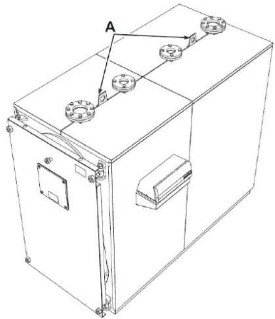
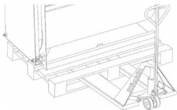
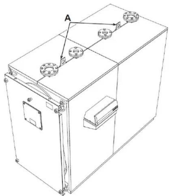
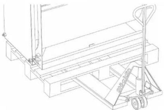
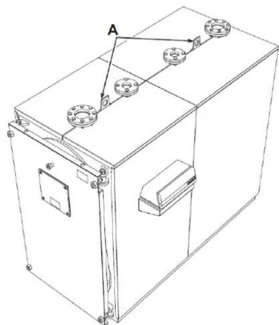
5.2 Handling
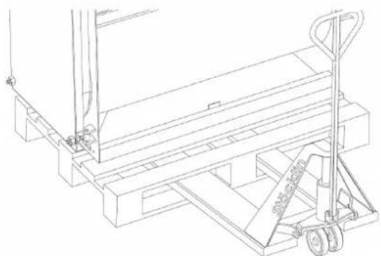
TP3 COND boilers have lifting hooks "A" (see fig. 3 and fig. 4). Be careful during handling, and use equipment suitable for the weight. Before positioning the boiler, remove the wooden base by undoing the fixing screws (fig. 5).
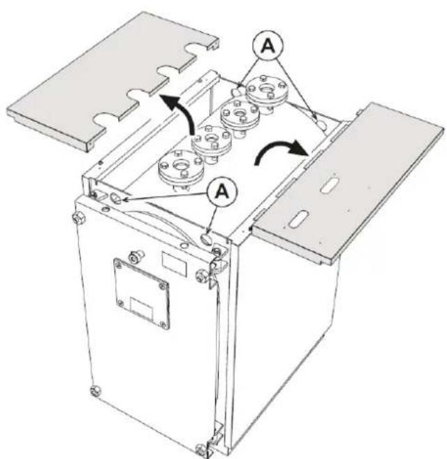
fig. 3 - From model TP3 COND 65 to TP3 COND 230
natural_image
Technical line drawing of a mechanical device with mounting flanges and a labeled component (no text or symbols present)fig. 4 - From model TP3 COND 370 to TP3 COND 1000
natural_image
Technical line drawing of a mechanical pallet jack with handle and wheels (no text or symbols)fig. 5 - Positioning
5.3 Installation room
TP3 COND boilers must be installed in dedicated rooms, meeting the current Technical Standards and Legislation and equipped with adequate ventilation openings. The ventilation openings must be permanent, communicating directly with the outside and located at the top and bottom in accordance with current regulations. The location of the ventilation openings and the fuel supply, electricity and lighting circuits must comply with the regulations in force according to the type of fuel used. To facilitate cleaning the smoke circuit, at the front of the boiler there must be a free space of at least the length of the boiler body and, in any case, never less than 1300 mm; it is also necessary to check that, with the door open 90°, the distance between the door and the adjacent wall (fig. 6) is at least equal to the length of the burner.
The boiler support surface must be perfectly horizontal. It is advisable to provide a flat cement plinth able to take the total weight of the boiler plus the water. For the plinth dimensions, see the dimensions P x D (see table on pag. 52). If the burner is fed with fuel gas of specific weight greater than that of the air, the electrical parts must be placed more than 500 mm above the floor. The appliance cannot be installed outdoors because it is not designed to operate outside and does not have automatic anti-freeze systems.
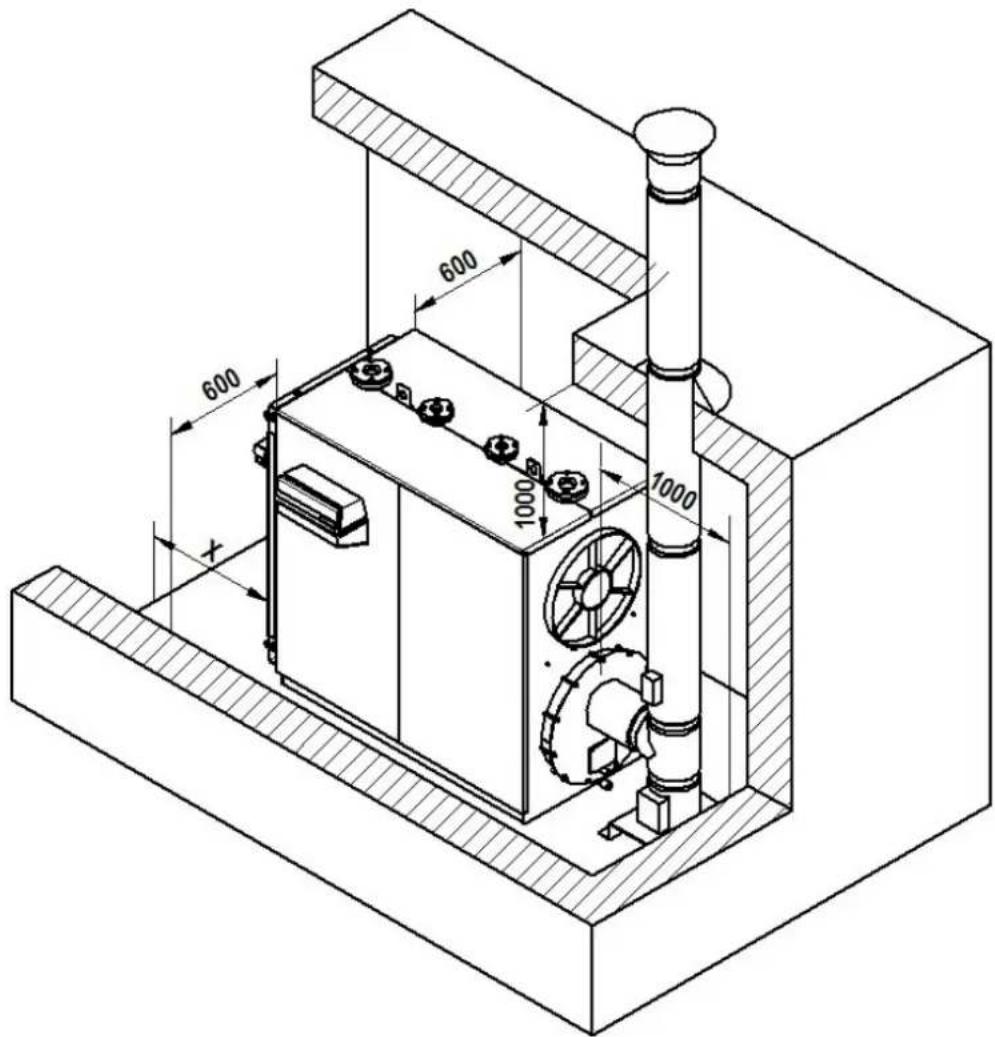
fig. 6 - Installation room
INSTALLATION IN OLD SYSTEMS OR SYSTEMS TO BE UPGRADED
When the boiler is installed in old systems or systems to be upgraded, make sure:
- The flue is suitable for the fume temperatures, calculated and built according to the current Regulations, and that it is tight, isolated, and has no occlusions or constrictions.
- The electrical system is carried out by qualified personnel in compliance with the current Regulations.
- The fuel supply line and possible tank comply with the current Regulations.
- The expansion vessel is adequate for the expansion of the fluid in the system.
- The capacity, head and flow direction of the circulating pumps are appropriate.
- The system is washed, cleaned of sludge and scale, vented and tight.
- A feed/replenishing water treatment system is provided (see reference values).
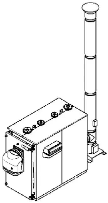
5.4 Discharge of combustion products
The flue pipe and flue connection must comply with the current Regulations and Legislation, using pipes that are resistant to heat, condensate and mechanical stresses, and be tight. The flue must ensure the minimum negative pressure required by the current Regulations, considering "zero" pressure at the flue pipe connection. Inadequate or incorrectly sized flues and flue pipes can increase the noise of combustion, generate condensation problems and adversely affect the combustion parameters. Non-insulated discharge pipes are a potential source of danger. The seals of the joints must be in materials resistant to temperatures of at least 100°C. In the connection section between the boiler and flue, there must be suitable measuring points for the smoke temperature and combustion products analysis. Regarding the section and height of the flue, refer to the national and local regulations in force.
ATTENTION: Condensate can form inside the flue, due to the low temperature of the fumes
natural_image
Technical line drawing of a mechanical device with a vertical column and control panel (no text or symbols)fig. 7
5.5 Plumbing connections
5.5.1 System water characteristics
TP3 COND boilers are suitable for installation in heating systems with non-significant entry of oxygen (ref. systems "case I" EN14868). A separator (e.g. plate heat exchanger) must be provided in systems with continuous entry of oxygen (e.g. underfloor systems without antidiffusion pipes), or intermittent (e.g. in case of frequent replenishments).
The water inside a heating system must have the characteristics required by UNI8065, and comply with laws and regulations in force and the provisions of EN14688 (protection of metallic materials against corrosion).
The filling water (first filling and subsequent replenishment) must be clear, with hardness below 3^ F and treated with suitable chemical conditioners against the initiation of corrosion, that are not aggressive on metals and plastics, do not develop gases and, in low-temperature systems, do not cause proliferation of bacterial or microbial masses.
The water contained in the system must be periodically checked (at least twice a year during the season when the systems are used, as required by UNI8065) and have: possibly a clear appearance, hardness below 10^ F for new systems or 15^ F for existing systems, pH above 7 and below 8.5, iron content (Fe) below 0.5 mg/l, copper content (Cu) below 0.1 mg/l, chloride content below 50mg/l, electrical conductivity below 200 us/cm, and must contain chemical conditioners in a concentration sufficient to protect the system for at least one year. Bacterial or microbial loads must not be present in systems at low temperature.
Only use conditioners, additives, inhibitors and antifreeze liquids declared by the producer suitable for use in heating systems and that do not cause damage to the heat exchanger or other components and/or materials of the boiler and system.
Chemical conditioners must ensure complete deoxygenation of the water, contain specific protection for yellow metals (copper and its alloys), anti-fouling agents for scale, neutral pH stabilizers and, in low-temperature systems, specific biocides for use in heating systems.
Recommended chemical conditioners:
SENTINEL X100 and SENTINEL X200
FERNOX F1 and FERNOX F3
The unit is equipped with a frost protection system that activates the boiler in heating mode when the system delivery water temperature falls below 6^ C. The device is not active if the power and/or gas supply to the unit are turned off. If necessary, to protect the system use a suitable antifreeze liquid that meets the above requirements and provided for by UNI 8065.
In the presence of adequate chemical/physical system and feed water treatments and related high cyclicity controls able to ensure the required parameters, for exclusively industrial process applications the product can be installed in open-vessel systems with vessel hydrostatic height able to ensure compliance with the minimum operating pressure indicated in the product technical specifications.
The presence of deposits on the boiler exchange surfaces due to non-compliance with the above requirements will involve non-recognition of the warranty.
5.5.2 System delivery/return pipes
The sizes of the delivery and return pipes are given for each boiler model in the DIMENSIONS table.
Make sure the system has a sufficient number of vents. Boiler connections must not be stressed by the weight of the system connection pipes. Therefore the installer must provide for appropriate supports.
5.5.3 Condensate discharge
No part of the condensate discharge system must be narrower than the boiler condensate discharge system.
The connection to the drainage system must comply with the current legislation and any local regulations.
To prevent the combustion products from escaping into the boiler room, a trap ensuring a minimum head equal to the firebox pressure increased by 25 mm must be installed in the condensate discharge path. The connection section between the boiler and trap and between the trap and drain must have a slope of at least 3^ and be such as to prevent any accumulation of condensate.
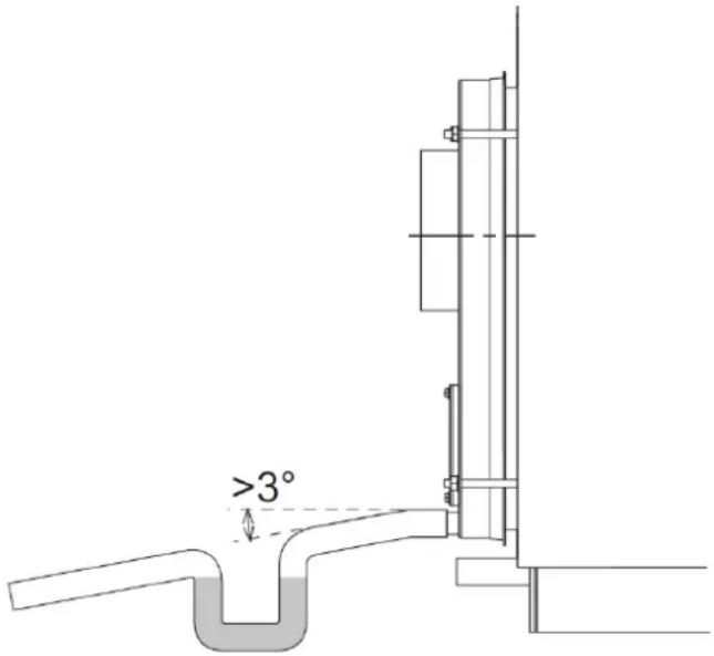
fig. 8 - Condensate discharge
5.5.4 System filling/draining pipes
For filling and draining the boiler a faucet can be connected to the fitting T5 located at the back (see fig. 2).
5.5.5 Safety valve and expansion vessel pipes
TP3 COND boilers are suitable for operating with forced water circulation with open or closed expansion vessel. An expansion vessel is always necessary in order to compensate the increase in water volume due to heating. In the first case, the height of the hydrostatic column should be at least 3 meters above the boiler casing and be able to contain, between the free water surface in the vessel and the overflow pipe, the increase in volume of all the water in the system. High and narrow vessels should be preferred in order to expose the smallest possible water surface to the air, thereby reducing evaporation. In the second case, the capacity of the closed expansion vessel must be calculated taking into account:
• total volume of water contained in the system
• system maximum operating pressure
- expansion vessel max. working pressure
- expansion vessel initial prefilling pressure
The expansion pipe connects the expansion vessel to the system. This pipe, which will start from the fitting T4 (see fig. 2), must not have a shut-off valve. Install on the fitting T4, or on the delivery pipe within 0.5 meters of the starting flange, a safety valve suitable for the boiler capacity and in accordance with the local and current regulations. It is forbidden to interpose any type of shut-off between the boiler and the expansion vessel and between the boiler and the safety valves; make sure to use valves adjusted for intervention within the maximum permitted working pressure.
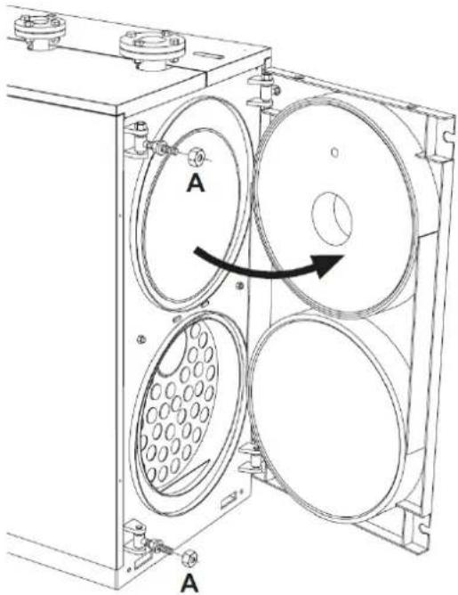
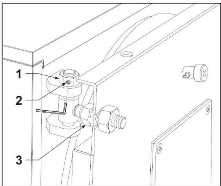
5.6 Front door opening and adjustment
Take note of the measurement "X" in fig. 9 at the 4 corners of the door.
Unscrew the 4 nuts "A" and locknuts "B" to near the end of the thread. Make sure the door does not fall off the flaring of the 4 nuts "A".
Nut "A" must be accompanied step by step with its locknut "B".
To open the door to the right, tighten the right nuts "A" and locknuts "B" with each other, remove the left nuts "A" and open the door.
To open the door to the left, tighten the left nuts "A" and locknuts "B" with each other, remove the right nuts "A" and open the door.
Once the door is closed, refit it place, gradually tightening the 4 nuts and locknuts alternately. Lastly, check fume tightness in operation.
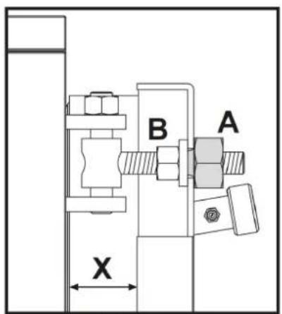
fig. 9
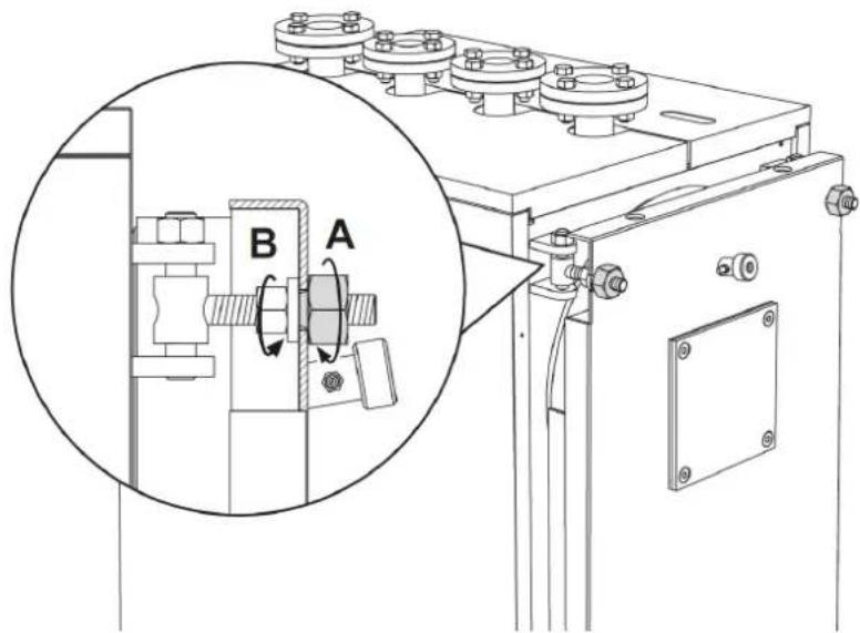
fig. 10
Door opening can be either left or right by unscrewing the respective nut (e.g. A - fig. 11).
- Door height adjustment is done with the nut (pos. 1); after adjusting, tighten the grub screws (pos. 2 - fig. 12).
• Lengthwise adjustment is done with the screw pos. 3 - fig. 12.
natural_image
Technical line drawing of a mechanical device with two circular components and labeled parts A (no text or symbols beyond labels)fig. 11 fig. 12
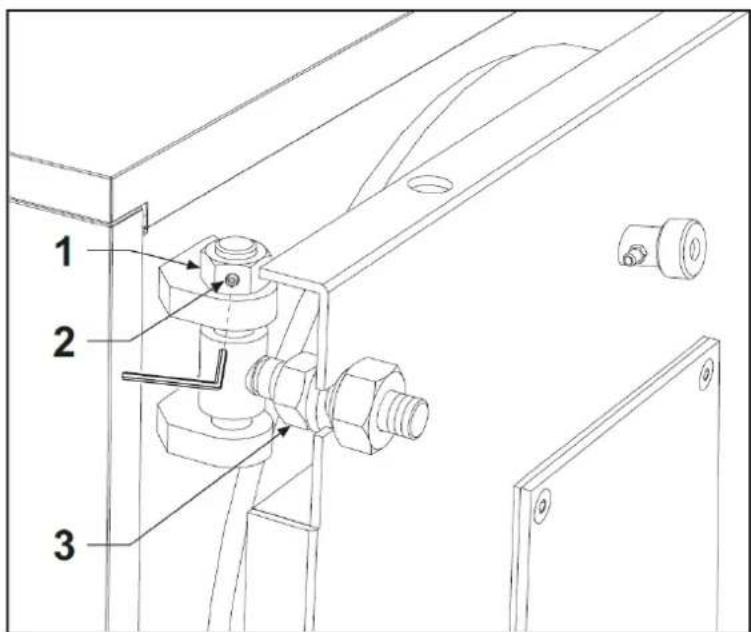
5.7 Burner assembly
Burner mounting on the boiler door must ensure perfect tightness to the combustion products. When the burner is installed on the boiler, the space between the burner nozzle and the refractory material of the door must be filled with the ceramic mat (ref. A - fig. 13) supplied. This prevents overheating of the door which would otherwise become permanently deformed. The ceramic mat is supplied as standard inside the combustion chamber.
natural_image
Technical line drawing of a mechanical assembly with labeled component A (no text or symbols beyond label)fig. 13
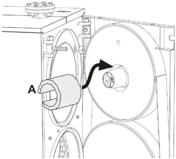
5.8 Flame control sight glass connection
The flame control sight glass has a pressure outlet (ref. 1 - fig. 14) to be connected to the burner outlet via a tube in silicone (not supplied) or copper. This operation allows the air blown by the fan to cool the glass and prevent blackening. Failure to connect the tube to the sight glass can cause the glass to break.
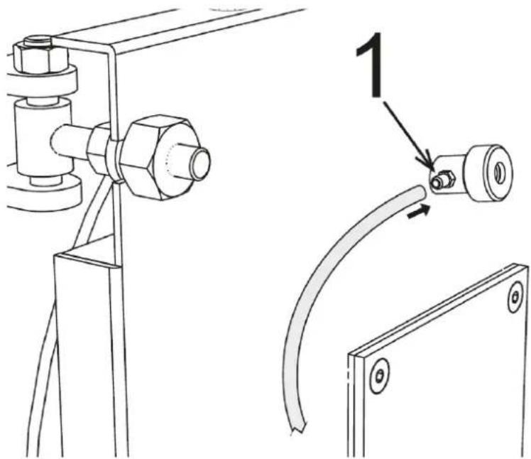
fig. 14
5.9 Probe and bulb positioning
The control panel is equipped with a temperature probe and three bulbs.
There are two wells "A" and "B" near the heating delivery "T1" (see fig. 15).
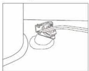
IT IS MANDATORY to insert in the well "A" (fig. 17) the temperature probe "4" and the safety thermostat bulb "3".
Insert in the well "B" (fig. 16), the bulb of the 1st stage thermostat (1) and that of the 2nd stage thermostat (2).
Make sure the probe and bulbs reach the end of the sheath.
Place the capillaries of the bulbs and probe as shown in fig. 18.
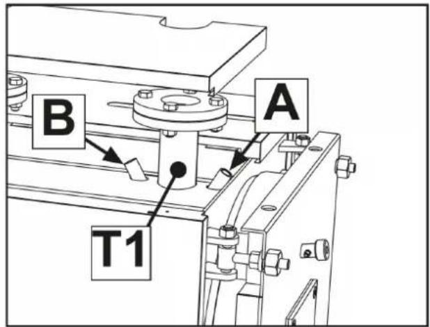
fig. 15 - Probe and bulb wells
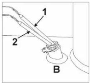
fig. 16 - Well B
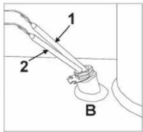
fig. 17 - Well A
natural_image
Simple line drawing of a mechanical component with curved lines and a circular base (no text or symbols)fig. 18
Legend
1 Thermostat bulb 1st Stage
2 Thermostat bulb 2nd Stage
3 Safety Thermostat bulb
4 Temperature probe
IMPORTANT
TO INSTALL ANOTHER TYPE OF TEMPERATURE CONTROL, IT IS NECESSARY TO USE AND INSTALL (AS PREVIOUSLY DESCRIBED) A SAFETY THERMOSTAT COMPLYING WITH THE CURRENT REGULATIONS, WITH INTERVENTION TEMPERATURE (SWITCHING POINT) = 110-6°C.
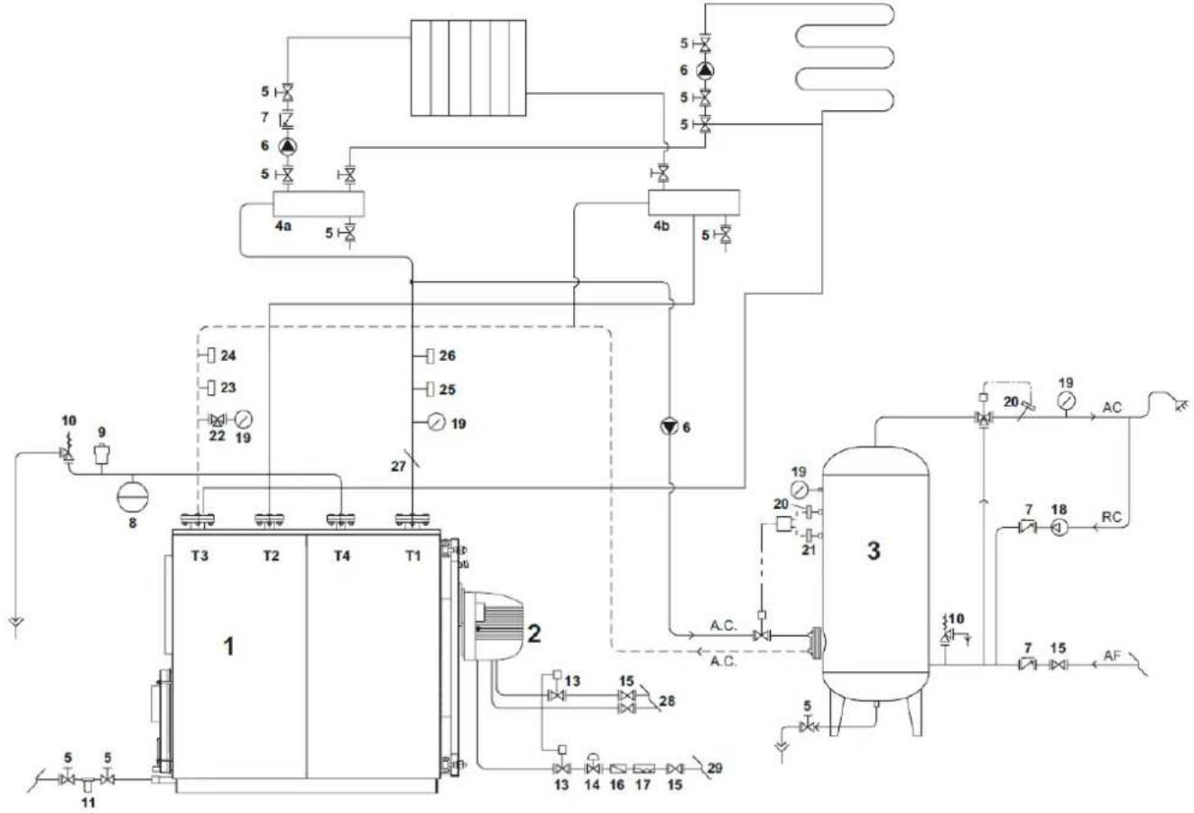
6. SCHEMATIC DIAGRAM - SYSTEM FOR HEATING AND DOMESTIC HOT WATER
The choice and installation of the system components is up to the installer, who must operate according to good practice and the current Legislation. Systems with antifreeze require the use of backflow preventers. Remember that the diagram in fig. 19 is a schematic diagram. In case of different systems, please contact our After-Sales Service which will provide all the elements you require.
flowchart
graph TD
    A["1"] --> B["T3"]
    A --> C["T2"]
    A --> D["T4"]
    A --> E["T1"]
    B --> F["2"]
    C --> G["26"]
    C --> H["25"]
    C --> I["19"]
    D --> J["27"]
    E --> K["2"]
    L["3"] --> M["A.C."]
    M --> N["13"]
    M --> O["15"]
    M --> P["28"]
    Q["4a"] --> R["5"]
    S["4b"] --> T["5"]
    U["5"] --> V["7"]
    W["6"] --> X["5"]
    Y["5"] --> Z["5"]
    AA["10"] --> AB["9"]
    AC["8"] --> AD["11"]
    AE["20"] --> AF["AC"]
    AG["19"] --> AH["RC"]
    AI["7"] --> AJ["18"]
    AK["15"] --> AL["AF"]
    AM["5"] --> AN["13"]
    AO["14"] --> AP["16"]
    AQ["17"] --> AR["15"]
    AS["20"] --> AT["13"]
    AU["21"] --> AV["15"]
    AW["27"] --> AX["20"]
fig. 19
Legend
T1 Heating delivery
T2 High temperature return
T3 Low temperature return
T4 Expansion vessel connection
1 Heat generator
2 Burner complete with shutoff and control valves
3 Hot water tank
4 System manifolds
5 Disconnecting valves
6 Circulating pump
7 Non-return valves
8 System expansion vessel
9 Automatic vent valve
10 Safety valve
11 Softener filter
12 System loading
13 Fuel shutoff valve
14 Gas pressure stabilizer
15 Manual shutoff valve
16 Gas filter
17 Vibration-damping coupling
18 Pump
19 Pressure gauge
20 Safety thermostat
21 Control thermostat
22 3-way valve
23 Manual reset pressure switch
24 Flow switch
25 Control thermostat
26 Manual reset thermostat
27 Temperature test well
28 Oil supply
29 Gas supply
7. STARTUP
7.1 Preliminary checks
After carrying out the plumbing, electrical and fuel connections to the boiler, before startup make sure:
- The expansion vessel and the safety valve (if required) are properly connected and cannot be shut off in any way.
- The bulbs of the operation, safety and minimum thermostats and the thermometer are secured within their respective sheaths.
- The turbulators are positioned in all the flue gas pipes
- The system is filled with water and completely vented.
• The pump/pumps work properly. - The hydraulic, electrical, safety and fuel connections comply with the current national and local regulations.
- The burner is mounted according to the instructions contained in the manufacturer's manual.
- The mains voltage and frequency are compatible with the burner and the boiler's electrical equipment.
- The system can absorb the amount of heat produced.
7.2 First ignition
After the positive outcome of the checks described above, it is possible to proceed with first ignition of the burner, which must be done by a technician enabled and approved by the burner Manufacturer.
The technician assumes all responsibility regarding the calibration range within the boiler's declared and approved power range. After opening the fuel shut-off valves and making sure there is no leakage in the feed network, turn all the switches ON. The burner is thus arranged for first ignition and for adjustment to be carried exclusively by the qualified technician. During first ignition, make sure the door, burner flange and the connections to the flue are tight and that the base of the flue has a slight negative pressure. The fuel flow must match the boiler rating and under no circumstances should it exceed the declared maximum rated power value.
7.3 Boiler shutdown
- Adjust the operating thermostat to minimum.
- Turn off the power to the burner and the fuel supply.
- Allow the pumps to run until they are stopped by the minimum thermostat.
- Turn off the power to the electrical panel.
8. MAINTENANCE
8.1 General rules
Periodic maintenance is essential for the safety, efficiency and service life of the unit. All operations must be carried out by qualified personnel. All cleaning and maintenance operations must be preceded by turning off the fuel supply, after disconnecting the power.
To ensure proper operation and maximum boiler efficiency, regularly clean the combustion chamber, flue gas pipes and smoke chamber.
8.2 Routine maintenance
Maintenance depends on the fuel used, the number of ignitions, system characteristics, etc., therefore a maintenance frequency or schedule cannot be fixed beforehand. In principle, the following cleaning intervals are advisable once a year.
In any case, the local regulations regarding maintenance must be observed. During routine maintenance, after removing the turbulators the tube bundle and firebox must be cleaned using a brush. Remove the accumulated deposits in the smoke box through the opening of the inspection doors. If necessary, remove the rear smoke chamber and replace the smoke seal if deteriorated. Make sure the condensate drain is not obstructed. Check the proper functioning of the generator control and measurement parts, and also the amount of replenishing water used. After analyzing the water, carry out preventive descaling. With repeated topping up, the calcium and magnesium salts dissolved in the raw water form deposits in the boiler and cause overheating of the plates with possible damage that cannot be attributed to the materials or the construction technique and therefore not covered by warranty. After carrying out maintenance, cleaning and subsequent lighting, check the door and smoke chamber seals and replace them in case of leakage of combustion products.
The operations carried out will be recorded in the heating system maintenance booklet.
8.3 Extraordinary maintenance
Extraordinary maintenance at end of season or for long periods of non-use.
It is necessary to carry out all the operations described in the previous section, and also:
- Check turbulator wear.
- Do not empty the system and boiler.
The operations carried out will be recorded in the heating system maintenance booklet.
8.4 Boiler cleaning
To carry out cleaning, proceed as follows (see fig. 20 and fig. 21):
- Open the front door (ref. 1) and remove the turbulators (ref. 2).
- Clean the inside of the combustion chamber and flueways using a brush (3 - not supplied) or other implements suitable for the purpose.
- Remove the accumulated deposits in the smoke box through the opening of the inspection doors (4). If necessary, remove the smoke box closure (5), replacing the seal before assembly.
• Periodically check that condensate drain (6) is not obstructed.
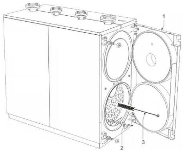
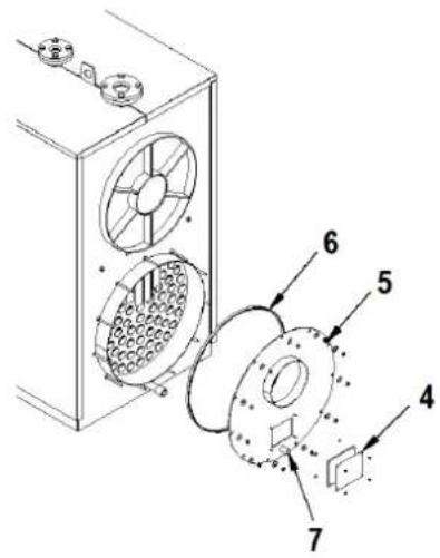
fig. 20 fig. 21
8.5 Boiler operation check
Before igniting the boiler and carrying out the functional check, make sure:
- the turbulators are correctly positioned with the exchange tubes.
• The hydraulic and fuel circuit valves are open.
• There is enough fuel available.
• The expansion vessel is properly loaded. - The hydraulic circuit pressure, when cold, is above 1 bar and below the boiler's maximum limit.
• The hydraulic circuits are vented. - The live-neutral connection must absolutely be respected; the ground connection is mandatory.
• The electrical connections to the power supply and components (burner, pump, control panel, thermostats, etc.) have been carried out.
After carrying out the above operations, to start the boiler:
- If the system is equipped with a temperature controller or programmable thermostat(s), check that they are "active".
- Set the room programmable thermostat(s) or temperature control to the desired temperature.
- Turn the system main switch "On"
- Set the boiler thermostat on the control panel to "On" and check lighting up of the green indicator.
The boiler will carry out the ignition phase and keep working until the set temperatures are reached. In case of ignition or operation faults, the boiler will do a "LOCKOUT" signaled by the red warning light on the burner and the red indicator on the control panel. After a "LOCKOUT" wait about 30 seconds before restoring the startup conditions. To reset startup conditions, press the burner "button/indicator" and wait for the flame to ignite. If this operation fails, it can be repeated 2-3 times, then check:
• The information provided in the burner instruction booklet.
• The section "BOILER OPERATION CHECK".
- The electrical connections on the diagram supplied with the control panel.
After startup, make sure the unit stops and then starts again:
- Changing the boiler thermostat setting.
- Operating the main switch on the control panel.
- Adjusting the room thermostat, timer programmer or temperature control.
- Checking the free and correct rotation of the circulating pumps.
- Checking complete boiler shutdown by operating the system main switch.
If all the conditions are met, restart the unit and check the combustion (smoke analysis), fuel flow rate and tightness of the door and smoke chamber seals.
8.6 Burner operation check
- See the burner instruction manual.
- Follow all the requirements of local regulations regarding burner maintenance.
8.7 Troubleshooting
The following boiler troubleshooting guide gives the main faults or failures that may occur, with possible causes and cures.
| FAULT | |||
| THE GENERATOR GETS DIRTY EASILY | |||
| CAUSE: Burner incorrectly adjusted CURE: Check burner adjustment (fume analysis) | |||
| Flue obstructed Clean the flueways and flue | |||
| Dirty burner air path Clean the burner air volute | |||
| THE GENERATOR DOES NOT HEAT | |||
| CAUSE: Dirty generator body Clean | |||
| Burner/generator combination Use a suitable burner | |||
| Insufficient burner capacity Restore the capacity | |||
| Control thermostat Check correct positioning of the capillary or replace the thermostat | |||
| THE GENERATOR GOES INTO THERMAL SAFETY SHUTDOWN STATUS WITH CONTROL PANEL WARNING LIGHT ON | |||
| CAUSE: Control thermostat CURE: Check proper operation | |||
| Check the set temperature | |||
| Check the electrical wiring | |||
| Check bulbs and probes | |||
| Lack of water Check the circuit. pressure | |||
| Presence of air Check the vent valve | |||
| THE GENERATOR IS WORKING BUT THE HEATING SYSTEM IS COLD | |||
| CAUSE: Air in the system CURE: Vent the system | |||
| Circulating pump fault | Free the circulating pump | ||
| Minimum thermostat (if present) | Check the set temperature | ||
| SMELL OF UNBURNT PRODUCTS | |||
| CAUSE: Smoke in the room CURE: Check generator body cleanness | |||
| Check fume duct cleanness | |||
| Check the tightness of generator, fume duct and flue | |||
| FREQUENT SAFETY VALVE INTERVENTION | |||
| CAUSE: System circuit pressure CURE: Check the load pressure | |||
| Check the system circuit | |||
| Check the calibration | |||
| Check the set temperature | |||
| System expansion vessel | Check | ||
4.4 Identification....81
4.5 Emballage 81
4.6 Manutention....81
4.7 Local d'installation....82
natural_image
Cross-sectional diagram of a mechanical device with internal flow arrows indicating material movement (no text or symbols)natural_image
Technical line drawing of a mechanical enclosure with mounting flanges and a labeled component (no text or symbols present)natural_image
Technical line drawing of a mechanical pallet jack with handle and wheels (no text or symbols)fig. 5 - Emplacement
natural_image
Technical line drawing of a mechanical device with a vertical column and control panel (no text or symbols)fig. 7
4.9 Raccordements hydrauliques
natural_image
Technical line drawing of a mechanical device with two circular components and labeled parts A (no text or symbols beyond labels)fig. 11 fig. 12
natural_image
Technical line drawing of a mechanical assembly with labeled component A (no text or symbols beyond label)fig. 13
natural_image
Technical line drawing of a mechanical assembly with two views: one showing a bolted joint and the other showing a curved pipe connection (no text or symbols present)fig. 14
natural_image
Simple line drawing of a mechanical component with curved lines and a circular base (no text or symbols)fig. 18
Légende
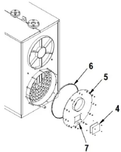
fig. 20 fig. 21


- CE
- Legenda
- Leyenda
- IMPORTANTE
- GENERAL INSTRUCTIONS
- Regulations
- Warranty conditions
- CERTIFICATIONS
- INTRODUCTION
- TECHNICAL, CONSTRUCTIVE AND DIMENSIONAL CHARACTERISTICS
- Description of unit
- Working principle
- Technical data - Dimensions - Hydraulic connections
- Legend
- Table of technical data, dimensions and connections
- ErP product fiche
- Identification
- - Bag documents
- - Data plate
- INSTALLATION
- Packing
- Handling
- Installation room
- INSTALLATION IN OLD SYSTEMS OR SYSTEMS TO BE UPGRADED
- Discharge of combustion products
- Plumbing connections
- System water characteristics
- System delivery/return pipes
- Condensate discharge
- System filling/draining pipes
- Safety valve and expansion vessel pipes
- Front door opening and adjustment
- Burner assembly
- Flame control sight glass connection
- Probe and bulb positioning
- IMPORTANT
- SCHEMATIC DIAGRAM - SYSTEM FOR HEATING AND DOMESTIC HOT WATER
- STARTUP
- Preliminary checks
- First ignition
- Boiler shutdown
- MAINTENANCE
- General rules
- Routine maintenance
- Extraordinary maintenance
- Boiler cleaning
- Boiler operation check
- Burner operation check
- Troubleshooting
- Raccordements hydrauliques
- Légende
Brand : FERROLI
Model : TP3 COND 65÷1000
Category : Boiler