
Atlas D Eco Cond Unit - Boiler FERROLI - Free user manual and instructions
Find the device manual for free Atlas D Eco Cond Unit FERROLI in PDF.
| Product Type | Oil-fired condensing boiler (diesel) |
| Brand | Ferroli |
| Model | Atlas D Eco Cond Unit (ATLAS D ECO 34 COND UNIT / ATLAS D ECO 45 COND UNIT) |
| Dimensions (L x W x H) | 34: 930 x 600 x 900 mm (approx.) 45: 1030 x 600 x 900 mm (approx.) |
| Empty weight | 34: 177 kg 45: 216 kg |
| Power supply | 230 V ~ 50 Hz, single-phase |
| Nominal thermal output (heating 80/60°C) | 34: 32 kW 45: 42 kW |
| Nominal thermal output (heating 50/30°C) | 34: 33.8 kW 45: 44.5 kW |
| Efficiency at 30% load (low temperature operation) | 34: 103.5% 45: 102.8% |
| Maximum heating circuit pressure | 3 bar |
| Minimum heating circuit pressure | 0.8 bar |
| Expansion vessel capacity | 10 litres (pre-charge 1 bar) |
| Main functions | Central heating and domestic hot water production (with optional external tank), climatic regulation with outdoor sensor, Summer/Winter mode, Eco/Comfort mode, compensation curve, self-diagnosis, frost protection |
| Burner | Forced draught oil burner, power adjustable, with ignition electrodes and photo-resistive cell |
| Circulator pump | High efficiency variable speed circulator pump (proportional or fixed setting) |
| Maintenance and cleaning | Annual check by qualified professional: cleaning of burner, heat exchanger, flue gas recuperator, checking of safety devices, water pressure, magnesium anode. External cleaning with damp cloth (no abrasive products). |
| Safety | Overheating sensor, frost protection, pressure switch, 3 bar safety valve, burner lockout device, self-diagnosis of anomalies (codes A01, A02, etc.) |
| Spare parts and repairability | Use only genuine Ferroli parts. Repairs by qualified professional. Easy access to burner, electrodes, nozzle, filters, and sensors. |
| General information | Manufacturer warranty under conditions. Compliant with CE standards. User manual included. Available languages: FR, NL, ES, IT, PL, GR. |
Frequently Asked Questions - Atlas D Eco Cond Unit FERROLI
User questions about Atlas D Eco Cond Unit FERROLI
0 question about this device. Answer the ones you know or ask your own.
Ask a new question about this device
Download the instructions for your Boiler in PDF format for free! Find your manual Atlas D Eco Cond Unit - FERROLI and take your electronic device back in hand. On this page are published all the documents necessary for the use of your device. Atlas D Eco Cond Unit by FERROLI.
USER MANUAL Atlas D Eco Cond Unit FERROLI
- Read the warnings in this instruction booklet carefully since they provide important information on safe installation, use and maintenance.
- This instruction booklet is an integral and essential part of the product and must be kept with care by the user for future reference.
- If the unit is sold or transferred to another owner or if it is to be moved, always make sure the booklet stays with the boiler so that it can be consulted by the new owner and/or installer.
- Installation and maintenance must be carried out by professionally qualified personnel, according to current regulations and the manufacturer's instructions.
- Incorrect installation or inadequate maintenance can result in damage or injury. The manufacturer declines any liability for damage caused by errors in installation and use or by failure to follow the instructions provided.
- Before carrying out any cleaning or maintenance operation, disconnect the unit from the power supply using the system switch and/or the special cut-off devices.
-
In case of a fault and/or poor operation, deactivate the unit and do not try to repair it or directly intervene. Contact professionally qualified personnel. Any repair/replacement of the products must only be carried out by qualified personnel using genuine parts. Failure to comply with the above can compromise the safety of the unit.
-
Periodic maintenance performed by qualified personnel is essential in order to ensure proper operation of the unit.
- This unit must only be used for its intended purpose. Any other use is deemed improper and therefore hazardous.
- After unpacking, check the good condition of the contents. The packing materials are potentially hazardous and must not be left within the reach of children.
- The unit can be used by children aged at least 8 years and by persons with reduced physical, sensory or mental capabilities, or lacking experience or the necessary knowledge, only if under supervision or they have received instructions on its safe use and the related risks. Children must not play with the unit. Cleaning and maintenance intended to be done by the user can be carried out by children aged at least 8 years only if under supervision.
- In case of doubt, do not use the unit. Contact the supplier.
- The unit and its accessories must be appropriately disposed of in compliance with current regulations.
- The images given in this manual are a simplified representation of the product. In this representation there may be slight and insignificant differences with respect to the product supplied.
| This symbol indicates “CAUTION” and is placed next to all safety warnings. Strictly follow these instructions in order to avoid danger and damage to persons, animals and things | |
| This symbols calls attention to a note or important notice. | |
| This symbol, which is used on the product, packaging or documents, means that at the end of its useful life, this product must not be collected, recycled or disposed of together with domestic waste. Improper management of electric or electronic waste can lead to the leakage of hazardous substances contained in the product. For the purpose of preventing damage to health or the environment, users are kindly asked to separate this equipment from other types of waste and to ask for it to be dealt with by the municipal waste service or dealer under the conditions and according to the methods set down in national and international laws transposing the Directive 2012/19/EU. Separate waste collection and recycling of unused equipment helps to save natural resources and to guarantee that this waste is processed in a manner that is safe for health and the environment. For more information about how to collect electric and electronic equipment and appliances, please contact your local Council or Public Authority competent to issue the relevant permits. |

The CE marking certifies that the products meet the essential requirements of the relevant directives in force.
The declaration of conformity may be requested from the manufacturer.
COUNTRIES OF DESTINATION: IT ES NL PL GR
1. OPERATING INSTRUCTIONS
1.1 Introduction
Dear Customer,
Thank you for choosing a FERROLI boiler featuring advanced design, cutting-edge technology, high reliability and quality construction. Please read this manual carefully since it provides important information on safe installation, use and maintenance.
ATLAS DECO COND UNIT is a high-efficiency condensing heat generator for heating and domestic hot water production (optional), equipped with a blown oil burner, wet fume chamber and fume heat recuperator in ceramic material. The boiler shell consists of castiron elements, assembled with double cones and steel stays. The control system is with microprocessor and digital interface with advanced temperature control functions.

The boller is arranged for connection to an external hot water storage tank (optional). In this manual all the functions relevant to domestic hot water production are only active with the optional hot water tank connected as indicated in sec. 2.3
1.2 Control panel
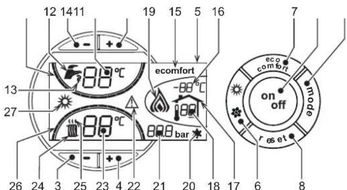
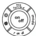
Panel
fig.1 - Control panel
Panel key
1 = DHW temperature setting decrease button
2 = DHW temperature setting increase button
3 = Heating system temperature setting decrease button
4 = Heating system temperature setting increase button
5 = Display
6 = Summer / Winter mode selection button
7 = Economy / Comfort mode selection button
8 = Reset button
9 = Unit On / Off button
10 = "Sliding Temperature" menu button
11 = Set DHW temperature reached
12 = DHW symbol
13 = DHW mode
14 = DHW outlet temperature / setting
15 = Eco (Economy) or Comfort mode
16 = External sensor temperature (with optional external probe)
17 = Appears on connecting the external Probe or the Remote Timer Control (optionals)
18 = Room temperature (with optional Remote Timer Control)
19 = Burner On
20 = Antifreeze operation
21 = Heating system pressure
22 = Fault
23 = Heating delivery temperature/setting
24 = Heating symbol
25=Heatingmode
26 = Set heating delivery temperature reached
27 = Summer mode
Indication during operation
Heating
A heating demand (generated by the Room Thermostat or Remote Timer Control) is indicated by flashing of the hot air above the radiator (details 24 and 25 - fig. 1).
The heating graduation marks (detail 26 - fig. 1) light up as the heating sensor temperature reaches the set value.
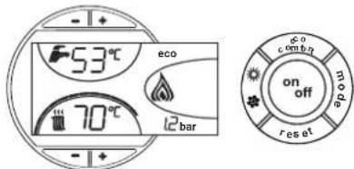
fig.2
DHW (Comfort)
A DHW demand (generated by drawing domestic hot water) is indicated by flashing of the hot water under the tap (details 12 and 13 - fig. 1). Make sure the Comfort function (detail 15 - fig. 1) is activated
The DHW graduation marks (detail 11 - fig. 1) light up as the DHW sensor temperature reaches the set value.
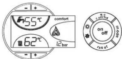
fig. 3
Exclude hot water tank (economy)
Hot water tank temperature maintaining/heating can be excluded by the user. If excluded, domestic hot water will not be delivered.
When hot water tank heating is activated (default setting), the COMFORT symbol (detail 15 - fig. 1) is activated on the display, and when off, the ECO symbol (detail 15 - fig. 1) is activated on the display
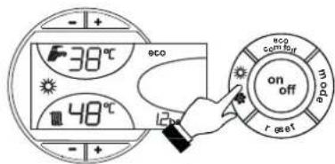
The hot water tank can be deactivated by the user (ECO mode) by pressing the eco/comfortfig. 1 button (detail 7 -). To activate the COMFORT mode, press the eco/comfort button (detail 7 -) fig. 1again.
1.3 Lighting and turning off
Boiler not electrically powered
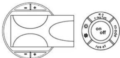
fig. 4 - Boiler not electrically powered
The antifreeze system does not work when the power and/or gas to the unit are turned off. To avoid damage caused by freezing during long idle periods in winter, it is advisable to drain all water from the boiler, DHW circuit and system; or drain just the DHW circuit and add a suitable antifreeze to the heating system, complying with that prescribed in sec. 2.3.
Boiler lighting
- Open the fuel on-off valves.
- Switch on the power to the unit.

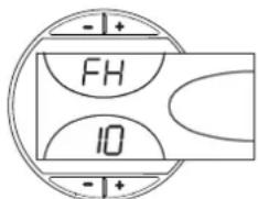
fig.5-Boiler lighting
For the next 120 seconds "FH" will be displayed in the upper part of the display, which identifies the heating system air venting cycle.
During the first 5 seconds the software version of the card will also be shown in the lower part of the display.
- When the message FH disappears, the boiler is ready to operate automatically whenever domestic hot water is drawn or in case of a room thermostat demand.
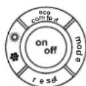
Turning the boiler off
Press the on/off button (detail 9 - fig. 1) for 1 second.
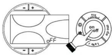
fig. 6 - Turning the boiler off
When the boiler is turned off, the PCB is still powered.
Domestic hot water and heating are disabled. The antifreeze system remains activated. To relight the boiler, press the on/off button (detail 9 fig. 1) again for 1 second.
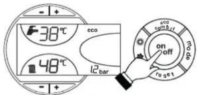
fig. 7
The boiler will be immediately ready to operate whenever domestic hot water is drawn or in case of a room thermostat demand.
1.4 Adjustments
Summer/Winter Swithover
Press the summer/winter button (detail 6 - fig. 1) for 1 second.
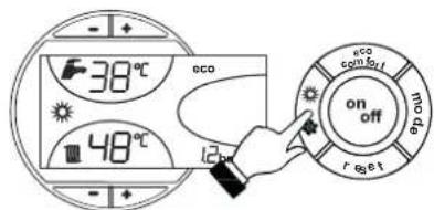
fig. 8
The display activates the Summer symbol (detail 27 - fig. 1): the boiler will only deliver domestic hot water. The antifreeze system remains activated.
To deactivate the Summer mode, press the summer/winter button (part. 6 - fig. 1) again for 1 second.
Heating temperature setting
Use the heating buttons (details 3 and 4 - fig. 1) to adjust the temperature from a min. of 30ircC to a max. of 80ircC .
In any case it is advisable not to operate the boiler below 45ircC
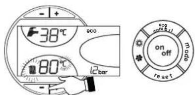
fig.9
DHW temperature adjustment
Use the DHW buttons (details 1 and 2 - fig. 1) to adjust the temperature from a min. of 10ircC to a max. of 65ircC .
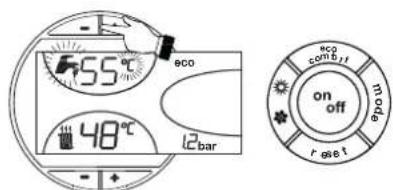
fig. 10
Room temperature adjustment (with optional room thermostat)
Using the room thermostat, set the temperature desired in the rooms. If the room thermostat is not installed the boiler will keep the heating system at its setpoint temperature.
Room temperature adjustment (with optional remote timer control)
Using the remote timer control, set the temperature desired in the rooms. The boiler unit will set the system water according to the required room temperature. For information on the remote timer control, please refer to its user's manual.
Sliding temperature
When the optional external probe is installed the control panel display (detail 5 - fig. 1) shows the actual outside temperature read by the probe. The boiler control system operates with "Sliding Temperature". In this mode, the temperature of the heating system is adjusted according the outside weather conditions, in order to ensure high comfort and energy saving throughout the year. In particular, as the outside temperature increases, the system delivery temperature is decreased according to a specific "compensation curve".
With Sliding Temperature adjustment, the temperature set with the heating buttons (details 3 and 4 - fig. 1) becomes the maximum system delivery temperature. It is advisable to set a maximum value to allow system adjustment throughout its useful operating range.
The boiler must be adjusted at the time of installation by qualified personnel. Possible adjustments can in any case be made by the user to improve comfort.
Compensation curve and curve offset
Press the mode button (detail 10 - fig. 1) once to display the actual compensation curve (fig. 11), which can be modified with the DHW buttons (details 1 and 2 - fig. 1).
Adjust the required curve from 1 to 10 according to the characteristic (fig. 13).
By setting the curve to 0, sliding temperature adjustment is disabled.
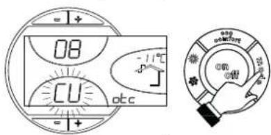
fig. 11 - Compensation curve
Press the heating buttons (details 3 and 4 - fig. 1) to access parallel curve offset (fig. 14), modifiable with the DHW buttons (details 1 and 2 - fig. 1).
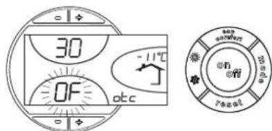
fig. 12 - Curve parallel offset
Press the mode button (detail 10 - fig. 1) again to exit parallel curve adjustment mode. If the room temperature is lower than the required value, it is advisable to set a higher order curve and vice versa. Proceed by increasing or decreasing in steps of one and check the result in the room.
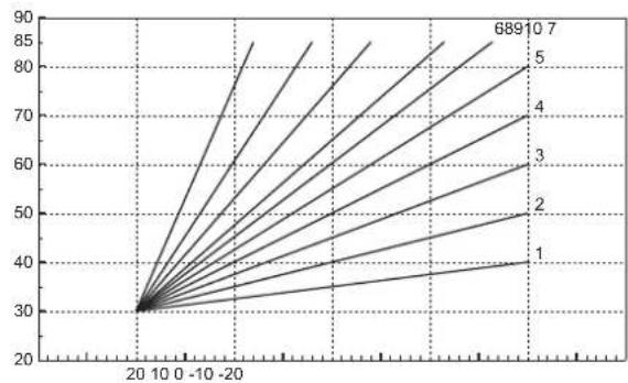
fig. 13 - Compensation curves
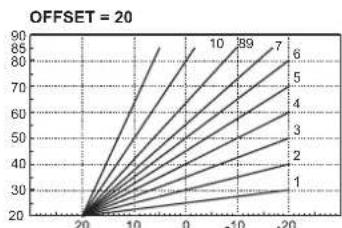
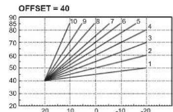
fig. 14 - Example of compensation parallel curve offset
Adjustments from Remote Timer Control

If the Remote Timer Control (optional) is connected to the boiler, the above adjustments are managed according to that given in table 1. Also, the control panel display (detail 5 - fig. 1) shows the actual room temperature detected by the Remote Timer Control.
Table.1
| Heating temperature setting | Adjustment can be made from the Remote Timer Control menu and the boiler control panel. |
| DHW temperature adjustment | Adjustment can be made from the Remote Timer Control menu and the boiler control panel. |
| Summer/Winter Swithover | Summer mode has priority over a possible Remote Timer Control heating demand. |
| Eco/Comfort selection | On disabling DHW from the Remote Timer Control menu, the boiler selects the Economy mode. In this condition, the button 7 - fig. 1 on the boiler panel is disabled. |
| On enabling DHW from the Remote Timer Control menu, the boiler selects the Comfort mode. In this condition it is possible select one of the two modes with the button 7 - fig. 1 on the boiler panel. | |
| Sliding Temperature | Both the Remote Timer Control and the boiler card manage Sliding Temperature adjustment: of the two, the Sliding Temperature of the boiler card has priority. |
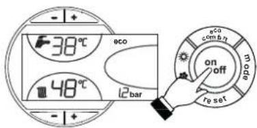
Water system pressure adjustment
The filling pressure with system cold, read on the display, must be approx. 1.0 bar. If the system pressure falls to values below minimum, the boiler card will activate fault F37 (fig. 15).
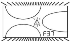
fig. 15 - Low system pressure fault

Once the system pressure is restored, the boiler will activate the 120-second air venting cycle indicated on the display by FH.
2. INSTALLATION
2.1 General Instructions
BOILER INSTALLATION MUST ONLY BE PERFORMED BY QUALIFIED PERSONNEL, IN ACCORDANCE WITH ALL THE INSTRUCTIONS GIVEN IN THIS TECHNICAL MANUAL, THE PROVISIONS OF CURRENT LAW, THE PRESCRIPTIONS OF NATIONAL AND LOCAL STANDARDS AND THE RULES OF PROPER WORKMANSHIP.
2.2 Place of installation
The boiler unit must be installed in a specific room with ventilation openings to the outside as prescribed by current regulations. If there are several burners or suction units that can work together in the same room, the ventilation openings must be sized for simultaneous operation of all the units. The place of installation must be free of flammable materials or objects, corrosive gases, powders or volatile substances that, conveyed by the burner fan, can obstruct the internal lines of the burner or the combustion head. The room must be dry and not exposed to rain, snow or frost.

If the unit is enclosed in a cabinet or mounted alongside, a space must be provided for removing the casing and for normal maintenance operations.
2.3 Plumbing connections
Important
The heating capacity of the unit must be previously established by calculating the building's heat requirement according to the current regulations. The system must be provided with all the components for correct and regular operation. It is advisable to install shutoff valves between the boiler and heating system allowing the boiler to be isolated from the system if necessary.

The safety valve outlet must be connected to a funnel or collection pipe to prevent water spurting onto the floor in case of overpressure in the heating circuit. Otherwise, if the discharge valve cuts in and floods the room, the boiler manufacturer cannot be held liable.
Do not use the water system pipes to earth electrical appliances.
Before installation, flush all the pipes of the system thoroughly to remove any residuals or impurities that could affect proper operation of the unit.
Carry out the relevant connections according to the diagram in cap. 4 and the symbols given on the unit.
High efficiency circulating pump
Circulating pump adjustment with boiler connected to an external hot water storage tank
For proper operation of the boiler ATLAS D ECO COND UNIT with it connected to an external hot water storage tank, the speed selector (see fig. 16) must be set to position III.
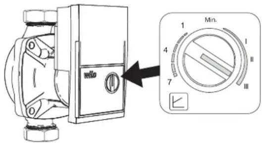
fig. 16
Circulating pump adjustment without a connection to an external hot water storage tank
The factory setting is suitable for all installations; however a different operation strategy can be set, depending on the characteristics of the system.
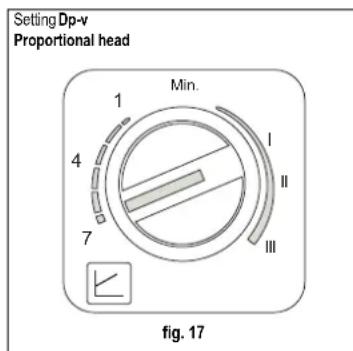
- Setting Dp-v Proportional head (fig. 17)
The circulating pump head will be automatically reduced with the decrease in flow rate required by the system. This setting is optimum for systems with radiators (2 pipes or single pipe) and/or thermostatic valves.
The strong points are the reduction in power consumption with the decrease in system demand and reduction of noise in radiators and/or thermostatic valves. The operating range is from min. (1) to max. (7).
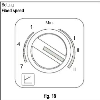
- Setting Fixed speed (fig. 18)
The circulating pump does not modulate its power. The operating principle is that of conventional 3-speed circulating pumps (with a reduction in power consumption compared to them). The operating range goes from speed 1 (I) to speed 3 (III).
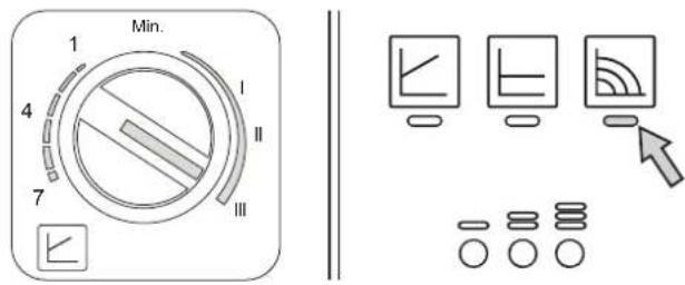
High-efficiency circulating pump (model PARA)
Control buttons and signaling LEDs
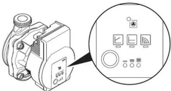
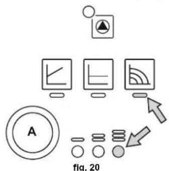
fig. 19
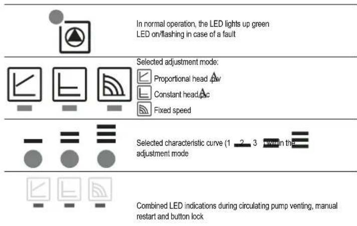
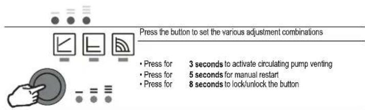
For a correct result of the "Thermal quantity balance" calculation (see section 11 THERMAL QUANTITY BALANCE (METERIN), the circulating pump must be set to "Constant speed" and to the position. To set this adjustment, press button "A" several times until the LEDs shown in the figure below light up.
However, a different operating strategy can be set, depending on the characteristics of the system.
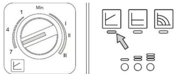
- Setting A-v Proportional Head
The circulating pump head will be automatically reduced with the decrease in flow rate required by the system.
The strengths are reduced power consumption as the system demand decreases, and reduced noise. The operating range is from minimum to maximum.
- Setting A-c Constant Head
The circulating pump head is constant as the flow rate required by the system varies.
- Setting Fixed speed
The circulating pump does not modulate its power. The operating principle is that of conventional 3-speed circulating pumps (with a reduction in power consumption compared to them). The operating range is from speed 1 (to speed 3 ( ).
Water system characteristics
In the presence of water harder than 25irc Fr (1ircF = 10ppm CaCO3), use suitably treated water in order to avoid possible scaling in the boiler. Treatment must not reduce the hardness to values below 15ircF (Decree 236/88 for uses of water intended for human consumption). Treatment of the water used is indispensable in case of very large systems or with frequent introduction of replenishing water in the system.
If water softeners are installed at the boiler cold water inlet, make sure not to reduce the water hardness too much, as this could cause early deterioration of the magnesium anode in the hot water tank.
Antifreeze system, antifreeze fluids, additives and inhibitors
The boiler is equipped with an antifreeze system that turns on the boiler in heating mode when the system delivery water temperature falls under 6ircC . The device will not come on if the electricity and/or gas supply to the unit are cut off. If it becomes necessary, it is permissible to use antifreeze fluid, additives and inhibitors only if the manufacturer of these fluids or additives guarantees they are suitable for this use and cause no damage to the heat exchanger or other components and/or materials of the boiler unit and system. It is prohibited to use generic antifreeze fluid, additives or inhibitors that are not expressly suited for use in heating systems and compatible with the materials of the boiler unit and system.
Connection to a storage tank for domestic hot water production
The unit's electronic board is arranged for managing an external storage tank for domestic hot water production. Make the plumbing connections according to the diagram fig. 21. Carry out: electrical connections as shown in the wiring diagram in cap. 4.5. A probe FERROL must be used.
Carry out the access procedure described below.
"Service Menu"
The card Service Menu is accessed by pressing the Reset button for 10 seconds.
Press the Heating buttons to select "tS", "In", "Hi" or "rE". "tS" means Transparent Parameters Menu, "In" Information Menu, "Hi" History Menu, and "rE" History Menu Reset. Select "tS" and press the Reset button.
The card has 20 transparent parameters also modifiable from Remote Control (Service Menu).
Press the Heating buttons to scroll the list of parameters in increasing or decreasing order. Press the DHW buttons to modify the value of a parameter: the change will be automatically saved.
Change parameter P02 of the "Transparent Parameters Menu" to 6.
Press the Reset button to return to the Service Menu. Press the Reset button for 10 seconds to exit to the card Service Menu.
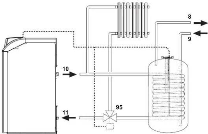
Fig. 21 - Diagram of connection to external hot water tank
Key
8 Domestic hot water outlet
9 Domestic cold water inlet
10 System delivery
11 System return
95 3-way valve - 2 wires with spring return (not provided)
2.4 Burner connection
The burner is equipped with flexible pipes and a filter for connection to the oil feed line. Run the flexible pipes out of the back and install the filter as indicated in fig. 22.
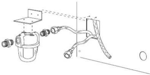
fig.22-Fuel filter installation
The oil feed circuit must be made according to one of the following diagrams, without exceeding the pipe lengths (LMAX) given in the table.
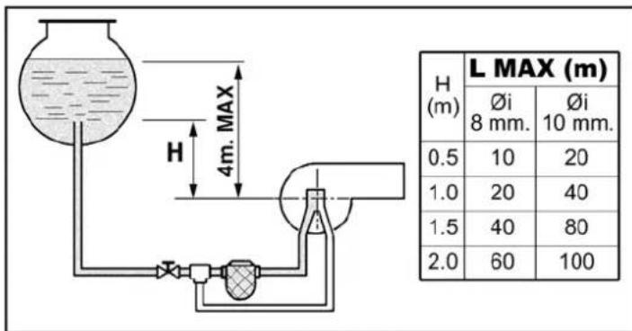
fig. 23 - Gravity feed
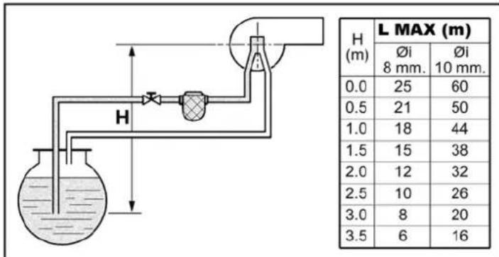
fig.24 - Suction feed
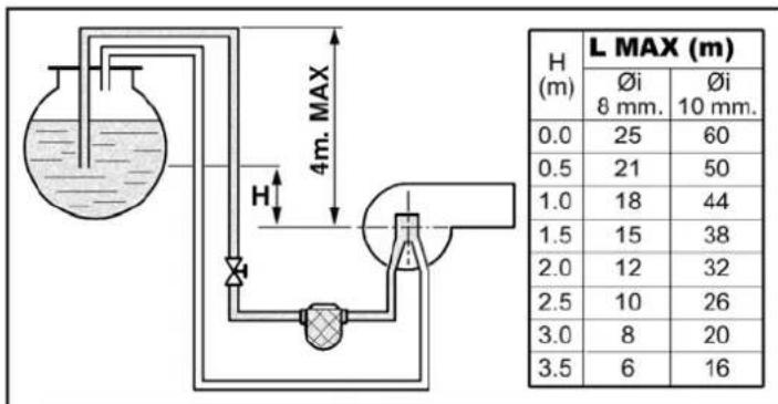
fig.25 - Siphon feed
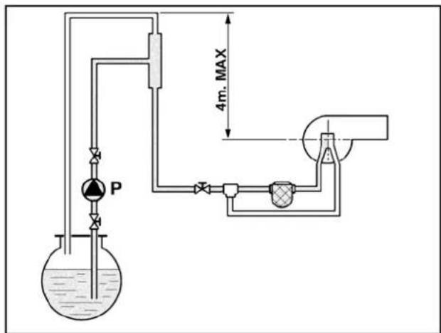
fig.26-Ring feed
2.5 Electrical connections
Connection to the electrical grid
The unit's electrical safety is only guaranteed when correctly connected to an efficient earthing system executed according to current safety standards. Have the efficiency and suitability of the earthing system checked by professionally qualified personnel. The manufacturer is not responsible for any damage caused by failure to earth the system. Also make sure that the electrical system is adequate for the maximum power absorbed by the unit, as specified on the boiler data-plate.
The boiler is prewired and provided with a Y-cable and plug for connection to the electricity line. The connections to the grid must be made with a permanent connection and equipped with a bipolar switch whose contacts have a minimum opening of at least 3 mm, interposing fuses of max. 3A between the boiler and the line. It is important to respect the polarities (LINE: brown wire / NEUTRAL: blue wire / EARTH: yellow-green wire) in making connections to the electrical line. During installation or when changing the power cable, the earth wire must be left 2 cm longer than the others.
The user must never change the unit's power cable. If the cable gets damaged, switch off the unit and have it changed solely by professionally qualified personnel. If changing the electric power cable, use solely "HAR H05 VV-F" 3x0.75 mm2 cable with a maximum outside diameter of 8 mm.
Room thermostat (optional)
IMPORTANT: THE ROOM THERMOSTAT MUST HAVE VOLTAGE-FREE CONTACTS. CONNECTING 230 V TO THE ROOM THERMOSTAT TERMINALS WILL PERMANENTLY DAMAGE THE ELECTRONIC BOARD.
When connecting time controls or a timer, do not take the power supply for these devices from their breaking contacts Their power supply must be by means of direct connection from the mains or with batteries, depending on the kind of device.
Accessing the electrical terminal block
Undo the two screws "A" located on the top part of the control panel and remove the cover.
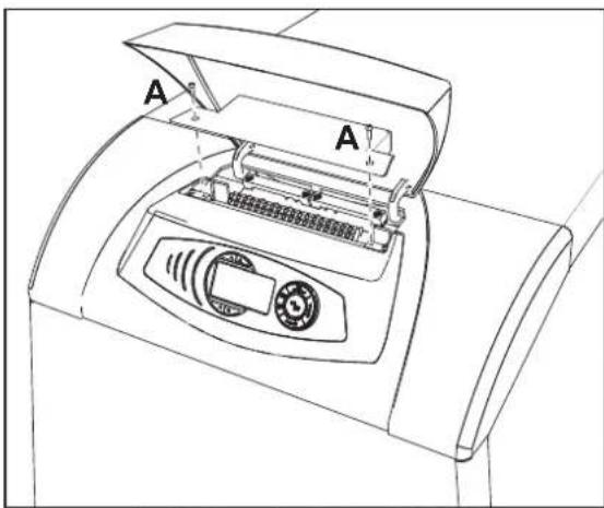
fig. 27 - Accessing the terminal block
2.6 Connection to the flue
The unit must be connected to a flue designed and built in compliance with the current regulations. The pipe between the boiler and flue must be made from material suitable for the purpose, i.e. heat and corrosion resistant. Ensure the seal at the joints.
2.7 Condensate drain connection
The unit's condensate drain must be connected to a suitable disposal system. Comply with the specific local and national regulations on discharging condensate water into the waste water disposal system. For boilers not using exclusively low-sulphur gas oil (S content < 50 ppm) make sure to provide for a suitable condensate neutralisation device. Connect the condensate drain pipe located at the back of the boiler (ref. A - fig. 28) to the neutralisation device connected to the waste water system. The condensate discharge pipes must be acidproof and installed sloping at least 3irc towards the drain, without any constrictions and obstructions.
IMPORTANT. Fill the trap with water before starting the unit.
ATTENTION: The unit must never be operated with the trap empty!
Periodically check the water in the trap.
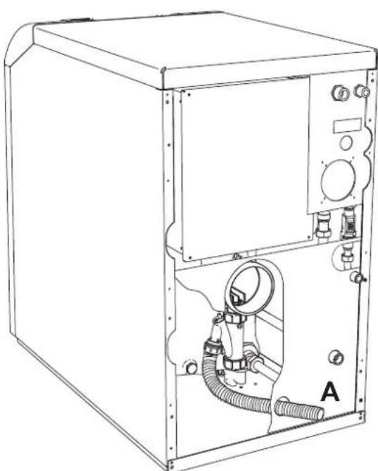
fig.28-Condensate drain
2.8 Conversion of boiler with burner to sealed chamber (only version ATLAS DECO 34 COND UNIT)
ATTENTION: The connection with separate pipes indicated here can be done only and exclusively with the sealed chamber kit.
A kit is available on request for converting the boiler with burner to sealed chamber. This conversion allows the air necessary for combustion to be sucked directly from the outside.
For installation, refer to the instructions contained in the kit.
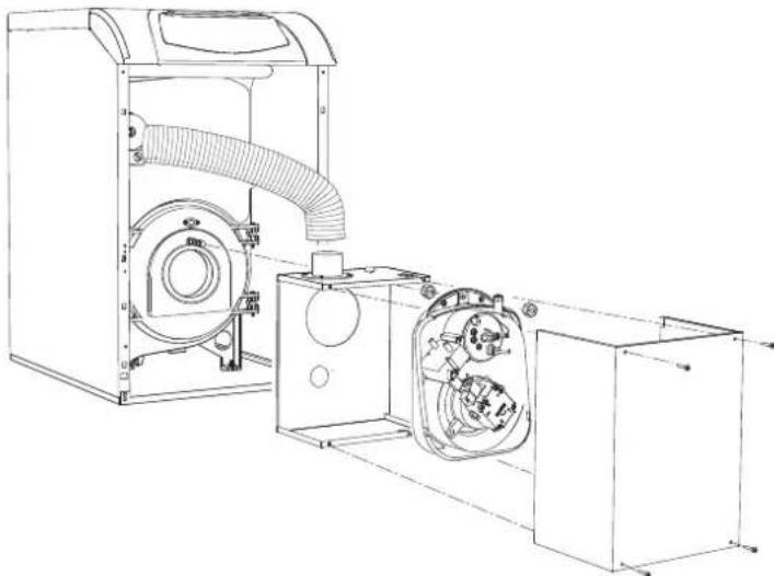
fig. 29 - Sealed chamber conversion kit
After installation, the unit becomes a "C type" with sealed chamber and forced draught. The air inlet and fume outlet must be connected to one of the extraction/suction systems specified below. The unit is approved to operate with all the Cxy flue configurations given in these instructions. Some configurations may be expressly limited or not permitted by law, standards or local regulations. Before proceeding with installation, check and carefully observe the above instructions. Also, comply with the provisions on the positioning of wall and/or roof terminals and the minimum distances from windows, walls, ventilation openings, etc.

Only use ducts in stainless steel, suitable for use with oil-fired condensing heat generators.
Connection with separate pipes
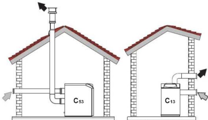
fig. 30 - Examples of connection with separate pipes (Air / Fumes)
Before installation, make sure the maximum permissible length has not been exceeded, by means of a simple calculation:
- Completely establish the layout of the system of split flues, including accessories and outlet terminals.
- Consult the table 3 and identify the losses in m eq (equivalent metres) of every component, according to the installation position.
- Check that the sum total of losses is less than or equal to the maximum permissible length in table 2.
Table. 2 - Separate ducts
| Separate ducts | |
| Model ATLAS D ECO 34 COND UNIT | |
| Max. permissible length | 25 m_eq |
Table. 3 - Accessories
| Losses in \( m_{eq} \) | |||||
| Air adjustment | Fume exhaust | ||||
| Vertical Horizontal | |||||
| Ø 80 PIPE | BEND | 0.5 m M/F 0.5 | |||
| 1 m M/F 1.0 | |||||
| 2 m M/F 2.0 | |||||
| 45° F/F 1.2 | |||||
| 45° M/F 1.2 | |||||
| 90° F/F 2.0 | |||||
| 90° M/F 1.5 | |||||
| 90° M/F + Test point 1.5 | |||||
| PIPE SECTION | with test point 0.2 | ||||
| for condensate drain | - | ||||
| TEE | for condensate drain | - | |||
| TERMINAL | air, wall 2.0 | ||||
| fumes, wall with antiwind | - | ||||
| FLUE | Split air/fumes 80/80 | - | |||
| Fume outlet only Ø80 | - | ||||
| Ø 100 | REDUCTION | from Ø80 to Ø100 | 0.0 | ||
| from Ø100 to Ø80 | 1.5 | ||||
| PIPE | 1 m M/F 0.4 0.4 | 0.8 | |||
| BEND | 45° M/F 0.6 1.0 | ||||
| 90° M/F 0.8 1.3 | |||||
| TERMINAL | air, wall 1.5 | - | |||
| fumes, wall with antiwind | - | 3.0 | |||
3. SERVICE AND MAINTENANCE
All adjustment, conversion, commissioning and maintenance operations described below must only be carried out by Qualified Personnel (meeting the professional technical requirements of current regulations) such as the personnel of the Local After-Sales Technical Service.
FERROLI declines any liability for damage and/or injury caused by unqualified and unauthorized persons tampering with the unit.
3.1 Adjustments
TEST mode activation
Press the heating buttons (details 3 and 4 - fig. 1) together for 5 seconds to activate the
TEST mode. The boiler switches on irrespective of the system or DHW request
The heating symbol (detail 24 - fig. 1) and DHW symbol (detail 12 - fig. 1) flash on the display.
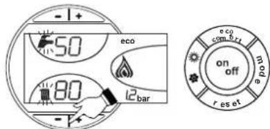
fig. 31 - TEST mode
To deactivate the Test mode, repeat the activation sequence.
The TEST mode is automatically disabled in any case after 15 minutes.
Burner adjustment
The burner is factory-set. The burner can be set to a different output by acting on the pump pressure, nozzle, head adjustment, and air adjustment as per the following paragraphs. In any case, the new adjusted output must fall within the boiler's nominal operating range. After making any adjustments, using a combustion analyser check that the CO2 content in the fumes is between 11% and 12% .
Nozzle flow rate table for oil
table 4 gives the oil flow rates (in kg/h) according to the change in pump pressure and nozzles.
N.B. - The values given below are only approximate, since nozzle flow rates can vary by ± 5% . Also, with burners having a preheater, the fuel flow rate decreases by about 10% .
Table.4
| Pump pressure (bar) | |||||||
| NOZZLE GPH. | 8 | 9 | 10 | 11 | 12 | 13 | 14 |
| 0.40 | 1.32 | 1.40 | 1.47 | 1.54 | 1.61 | 1.68 | 1.75 |
| 15.66 | 16.60 | 17.43 | 18.26 | 19.09 | 19.92 | 20.75 | |
| 0.50 | 1.57 | 1.65 | 1.73 | 1.81 | 1.89 | 1.97 | 2.05 |
| 18.62 | 19.57 | 20.51 | 21.50 | 22.42 | 23.36 | 24.31 | |
| 0.60 | 1.93 | 2.01 | 2.23 | 2.32 | 2.42 | 2.52 | 2.64 |
| 22.89 | 23.83 | 26.44 | 27.51 | 28.70 | 29.88 | 31.31 | |
| Pump pressure (bar) | |||||||
| 0.65 | 2.12 | 2.25 | 2.40 | 2.63 | 2.74 | 2.80 | 2.91 |
| 25.14 | 26.68 | 28.46 | 31.19 | 32.49 | 33.21 | 34.51 | |
| 0.75 | 2.50 | 2.65 | 2.80 | 2.95 | 3.07 | 3.20 | 3.33 |
| 29.65 | 31.43 | 33.21 | 34.99 | 36.41 | 37.95 | 39.49 | |
| 0.85 | 2.92 | 3.10 | 3.27 | 3.45 | 3.60 | 3.75 | 3.90 |
| 34.63 | 36.76 | 38.78 | 40.92 | 42.69 | 44.47 | 46.25 | |
| 1.00 | 3.30 | 3.50 | 3.67 | 3.85 | 4.02 | 4.20 | |
| 39.13 | 41.51 | 43.52 | 45.66 | 47.67 | 48.72 | 51.95 | |
| Flow rate at nozzle outlet in kg/h | |||||||
Pump pressure adjustment
The pump is factory-set to 12 bar. Use an oil bath gauge to check the pressure. The pressure can be adjusted between 11 and 14 bar.
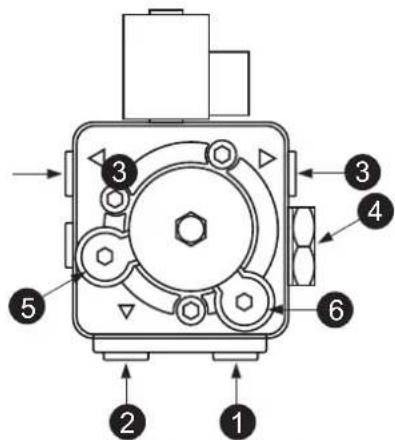
fig. 32-Pump ITALPUMP
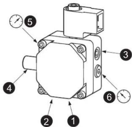
fig. 33-Pump DANFOSS
- Suction 01/4"
- Return 01/4
- Oil delivery 01/8"
- Pressure adjustment
- Pressure gauge connection 1 / 8irc
- Vacuum gauge connection 1 / 8irc
Combustion head adjustment
The head is adjusted by means of the screw 1, according to the indications of the pointer 2.
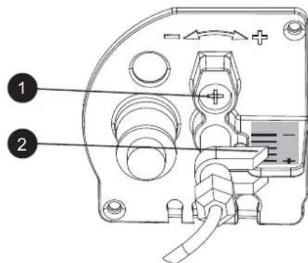
fig. 34
Air damper adjustment
After loosening the screw 3, operating the screw 1, the combustion air is adjusted according to the indications of the pointer 2. After adjustment, lock the screw 3.
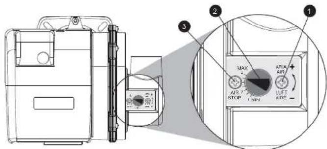
fig. 35
Position of electrodes - baffle
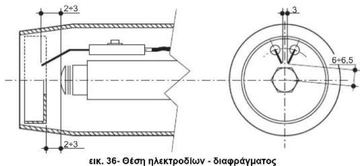
After fitting the nozzle, check correct positioning of the electrodes and baffle, according to the dimensions given below. It is advisable to check the dimensions after each operation on the head.
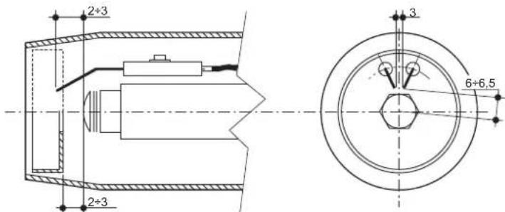
fig. 36- Position of electrodes - baffle
3.2 Commissioning
Checks to be made at first lighting, and after all maintenance operations involving disconnection from the systems or an operation on safety devices or parts of the boiler:
Before lighting the boiler
- Open any on-off valves between the boiler and the systems.
- Check the tightness of the fuel system.
- Check the pre-filling of the expansion tank
- Fill the water system and make sure that all air contained in the boiler and the system has been vented by opening the air vent valve on the boiler and any vent valves on the system.
- Make sure there are no water leaks in the system, hot water circuits, connections or boiler.
- Make sure the electrical system is properly connected and the earth system works properly.
- Make sure there are no flammable liquids or materials in the immediate vicinity of the boiler.
- Fit the pressure gauge and the vacuum gauge on the pump (remove after starting) of the burner.
open the gate valves along the diesel pipe
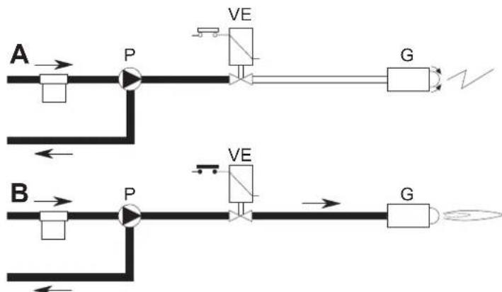
Start-up
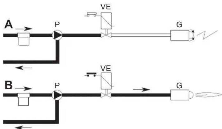
fig. 37 - Starting
A
When the thermostalic line closes, the burner motor starts turning together with the pump: all the oil sucked is sent to the return. The burner blower and the ignition transformer are also working, therefore the following stages are carried out:
- firebox prevention.
- prewash of a part of the oil circuit.
preignition, with discharge between electrode tips.
B
At the end of prewash, the unit opens the electromagnetic valve: the oil reaches the nozzle, where it is finely sprayed.
Its contact with the discharge between the electrode tips creates the flame.
The safety time begins simultaneously.
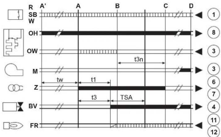
Unit cycle

fig. 38 - Unit cycle
R-SB-W Thermostats/Pressure switches
OH Oil pre-heater
OW Operation enabling contact
M Burner motor
Z Ignition transformer
BV Electromagnetic valve
FR Photoresistance
A' Starting with pre-h
A Starting without pre-heater
B Flame present
C Normal operation
D Adjustment stop (TA-TC)
t1 Pre-ventilation time
TSA Safety time
t3 Pre-ignition time
t3n Post-ignition time
tw Pre-heating time
Output signals from the unit
Necessary input signals
Checks during operation
- Ignite the appliance as described in sec. 1.3.
- Check that the fuel circuit and water systems are airtight.
- Check the efficiency of the flue and air-fume ducts while the boiler is working.
- Check that the water is circulating properly between the boiler and the systems.
- Check the proper ignition of the boiler by performing various tests, turning it on and off with the room thermostat or remote control.
- Check that the burner door and fume chamber are tight.
- Check that the burner works properly
- Analyse the combustion (with the boiler unit stable) and check that the content of COx in the fumes is between 11% and 12% .
- Check the parameters are programmed correctly and perform any required customization (compensation curve, power, temperatures, etc.).
3.3 Maintenance
Periodical check
To ensure correct operation of the unit over time, have qualified personnel carry out a yearly check, providing for the following:
The control and safety devices must function correctly.
The fume exhaust circuit must be perfectly efficient.
- Check there are no obstructions or dents in the fuel supply and return pipes.
- Clean the filter of the fuel suction line.
Measure the correct fuel consumption
- Clean the combustion head in the fuel outlet zone, on the swirl disc.
- Leave the burner running at full rate for approximately ten minutes, then analyse the combustion, checking:
- All the elements specified in this manual are set correctly
- Temperatures of the fumes at the flue
- CO2 percentage content
The air-fume end piece and ducts must be free of obstructions and leaks
- The burner and exchanger must be clean and free of deposits. For possible cleaning do not use chemical products or wire brushes.
The gas and water systems must be airtight.
- The water pressure in the cold water system must be approx. 1 bar; otherwise, bring it to that value.
The circulating pump must not be blocked.
The expansion tank must be filled.
- Check the magnesium anode and replace it if necessary.

The boiler casing, control panel and aesthetic parts can be cleaned with a soft and damp cloth, if necessary soaked in soapy water. Do not use any abrasive detergents and solvents.
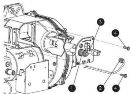
Accessing the electrode and nozzle
- Disconnect the transformer electrode cables and remove the photoresistance 1, and the union 2 connecting the oil pipe to line 3 of the nozzle. Loosen the screws 4 and pull out the nozzle-baffle-electrode flange assembly.
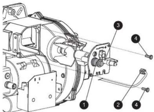
fig. 39
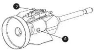
- Undo the screw 5 to remove the baffle and screw 6 to remove the electrodes. Proper cleaning of the nozzle is obtained by removing the filter and cleaning the slots and spraying hole with petrol, rinsing it with fuel oil. When reassembling everything, pay attention to the correct positioning of the electrodes-baffle.
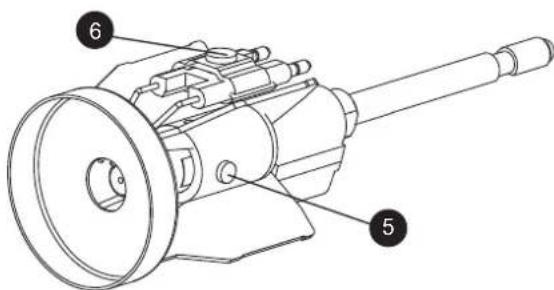
fig. 40
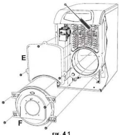
Boiler cleaning
- Disconnect the power supply to the boiler.
- Remove the burner as described above.
- Remove the panels "E" and "F" undoing the respective nuts
- Clean the inside of the boiler and the entire path of exhaust fumes, using a tube brush or compressed air.
- Close the panels.

fig.41
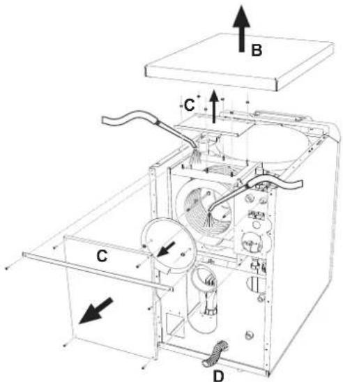
Cleaning the fume recuperator
To clean the fume recuperator:
- Remove the cover B.
- Remove the fume recuperator closing covers C
- Carefully clean the inside of the recuperator using an aspirator.
- If particularly dirty, a suitable device for spraying water inside can be used. In this case, make sure large amounts of water do not come into contact with the cast iron elements in the smoke chamber. Run the water through the condensate drain D after disconnecting the trap.

fig. 42 - Cleaning the recuperator
Positioning of combs
After cleaning the recovery unit make sure the combs are positioned correctly, as shown in fig. 43. Tighten the nuts on the compressor disk "A" respecting the torque setting of 0.6Nm . If a torque wrench is unavailable, check that there is a fume passage of 1mm between the coils.

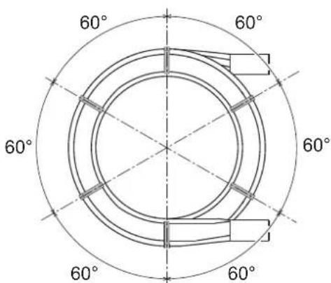
fig. 43 - Positioning of combs
3.4 Troubleshooting
Diagnostics
The boiler is equipped with an advanced self-diagnosis system. In case of a boiler fault, the display will flash together with the fault symbol (detail 22 - fig. 1) indicating the fault code.
There are faults the cause permanent shutdowns (marked with the letter "A"): to restore operation, just press the RESET button (detail 8 - fig. 1) for 1 second or use the RESET on the remote timer control (optional) if installed; if the boiler does not restart, it is necessary to eliminate the fault indicated in the operation LEDs.
Other faults cause temporary shutdowns (marked with the letter "F") which are automatically reset as soon as the value returns within the boiler's normal working range.
ATTENTION
From software version 23, an additional feature has been introduced to facilitate burner calibration, i.e. flame flashing on the display to indicate that the burner is on but with indication of non-optimal flame.
For the various software versions, the meanings of the symbols shown on the display can be found in the table 1.
Table. 5- Flame symbol indications
| Indication on the display and meaning | |||
| Software Version | Flame Off Flame On Steady | Flame Flashing | |
| ≤22 | Burner off Burner on | - | |
| ≥23 | Burner off | Burner on and indication of stable flame | Burner on with indication of NOT optimal flame |
Table. 6 - List of faults
| Fault code | Fault Possible cause | use Cure | |
| A01 Burner block | Pump blocked Replace | ||
| Faulty electric motor Replace | |||
| Faulty oil valve Replace | |||
| No fuel in tank, or water on bot- tom | Refill with fuel or suck the water | ||
| Oil line feed valves closed Open | |||
| Dirty filters (line-pump-nozzle) Clean | |||
| Pump unprimed Prime and find the cause of unpriming | |||
| Ignition electrodes not properly adjusted, or dirty | Adjust or clean them | ||
| Nozzle clogged, dirty or deformed | Replace | ||
| Unsuitable head and shutter adjustments | Adjust | ||
| Faulty electrodes or earthed Replace | |||
| Faulty ignition transformer Replace | |||
| Faulty electrode wires or earthed Replace | |||
| Electrode wires deformed by high temperature | Replace and protect | ||
| Faulty valve or transformer elec- trical connections | Check | ||
| Broken pump-motor joint Replace | |||
| Pump inlet connected to return pipe | Correct the connection | ||
| Faulty photoresistance | Replace | ||
| Dirty photoresistance | Clean the photoresistance | ||
| A02 | Flame present signal with burner off | Photoresistance short circuit | Replace the photoresist- ance |
| Extraneous light strikes the pho- toresistance | Eliminate the light source | ||
| A03 | Overtemperature protection activa- tion | Heating sensor damaged | Check the correct position- ing and operation of the heating sensor |
| No water circulation in the sys- tem | Check the circulating pump (See table 7) | ||
| Air in the system | Vent the system | ||
| A04 | Card parameter fault | Wrong card parameter setting | Check the card parameter and modify it if necessary |
| F07 | Preheater fault (the contact does not close in 120 seconds) | Preheater fault | Check the preheater |
| Wiring disconnected Check the wiring | |||
| F09 | Card parameter fault | Wrong card parameter setting | Check the card parameter and modify it if necessary |
| F10 | Delivery sensor 1 fault | Sensor damaged | Check the wiring or replace the sensor |
| Wiring shorted | |||
| Wiring disconnected | |||
| Fault code | Fault Possible cause | Use Cure | |
| F11 | DHW sensor fault | Sensor damaged | Check the wiring or replace the sensor |
| Wiring shorted | |||
| Wiring disconnected | |||
| F12 | Card parameter fault | Wrong card parameter setting | Check the card parameter and modify it if necessary |
| F14 | Delivery sensor 2 fault | Sensor damaged | Check the wiring or replace the sensor |
| Wiring shorted | |||
| Wiring disconnected | |||
| F16 | Card parameter fault | Wrong card parameter setting | Check the card parameter and modify it if necessary |
| F34 | Supply voltage under 170V. | Electric mains trouble | Check the electrical system |
| F35 | Faulty mains frequency | Electric mains trouble | Check the electrical system |
| F37 | Incorrect system water pressure | Pressure too low | Fill the system |
| Sensor damaged | Check the sensor | ||
| F39 | External probe fault | Probe damaged or wiring shorted | Check the wiring or replace the sensor |
| Probe disconnected after activat-ing the sliding temperature | Reconnect the external sen-sor or disable the sliding temperature | ||
| F40 | Incorrect system water pressure | Pressure too high | Check the system |
| Check the safety valve | |||
| Check the expansion tank | |||
| A41 | Sensor position-ing | Delivery sensor not inserted in boiler shell | Check the correct position-ing and operation of the heating sensor |
| F42 | Heating sensor fault | Sensor damaged | Replace the sensor |
| F47 | System water pressure sensor fault | Wiring disconnected | Check the wiring |
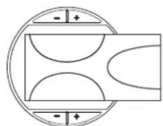
Circulating pump diagnostics
Some faults linked to the circulating pump are signalled by the LED located around the speed selector (fig. 44 - fig. 45).
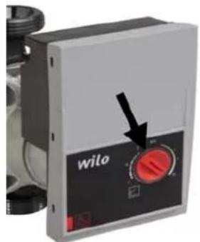
fig. 44
Table. 7 - Circulating pump LED indications
| 4 1 7 6 | Off Circulating pump on STANDBY |
| Green ON Circulating pump Working | |
| Green Flashing Air venting cycle | |
| Green/Red alternating Circulating pump blocked due to external causes: - Overvoltage (>270V) - Insufficient voltage (<160V) - Motor overload | |
| Red Flashing Circulating pump blocked due to internal causes: - Motor blocked - Damaged electronics |
Circulating pump diagnostics (model PARA)
Some faults linked to the circulating pump are signaled by the LED (fig. 45).
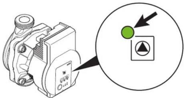
fig. 45
| LED Fault Cause Cure | |||
| On with red light | Fault Blacked rotor | Activate manual restart or contact Customer Service | |
| Contact/winding Faulty winding | |||
| Flashing with red light | Under/overvoltage Supply side voltage too low/high | Check the mains voltage and conditions of use. Request Customer Service | |
| Excessive module temperature | Inside of module too hot | ||
| Short circuit Motor current too high | |||
| Flashing with red/green light | Turbine operation | The hydraulic system of pumps is fed but the pump does not have mains voltage | Check the mains voltage, the water flow/pressure as well as the environmental conditions |
| Dry running Air in pump | |||
| Overload | The motor turns with difficulty. Pump operation not in accordance with specifications (e.g. high module temperature). The speed is lower than in normal operation. | ||
4. TECHNICAL DATA AND CHARACTERISTICS
4.1 Main components, dimensions and connections
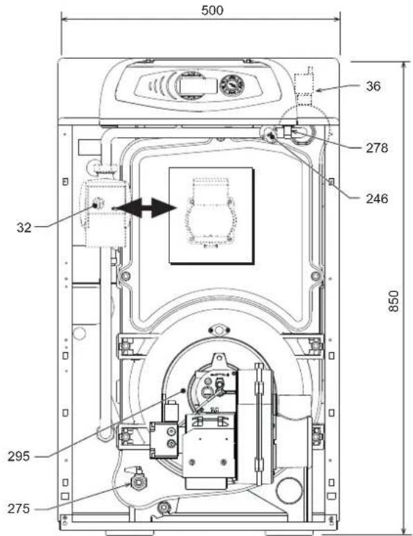
fig.46-Frontview
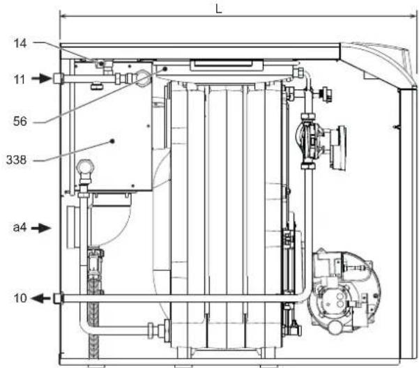
fig. 47- Side view
| L | |
| ATLAS D ECO 34 COND UNIT | 930 |
| ATLAS D ECO 45 COND UNIT | 1030 |
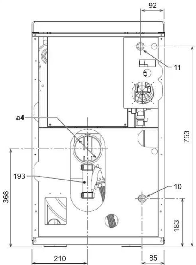
fig.48 - Rear view
a4 Flue 0100
10 System delivery - 0 3/4"
11 System return - 0 3/4
14 Heating safety valve
32 Heating circulating pump
36 Automatic air vent
56 Expansion tank
193 Trap
246 Pressure transducer
275 Drain - 0 1/2
278 Double sensor (Safety + heating)
295 Burner
338 Fumes recuperator
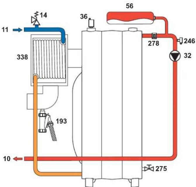
4.2 Water circuit
fig.49-Water circuit
4.3 Diagrams
Circulating pumps Head/Pressure loss
- Circulating pump with "fixed speed" setting.
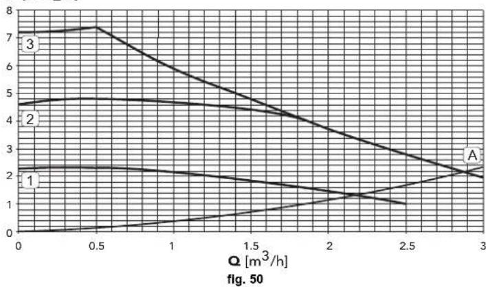
H [m H2O]
A Boiler pressure losses
1-2-3 Circulating pump speed
- Circulating pump with "proportional head" setting.
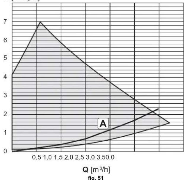
H [m H2O]
A Boiler pressure losses
4.4 Technical data table
| Data | Unit | ATLAS DECO 34 COND UNIT | ATLAS DECO 45 COND UNIT | |
| Number of elements no. 3 4 | ||||
| Max. heating capacity kW 33.0 43.5 (Q) | ||||
| Min. heating capacity kW 16.3 30.9 (Q) | ||||
| Max. heat output in heating (80/60) | kW | 32 | 42 | (P) |
| Min. heat output in heating (80/60) | kW | 16 | 30 | (P) |
| Max. heat output in heating (50/30) kW 33.8 44.5 (P) | ||||
| Min. heat output in heating (50/30) | kW | 17.0 | 31.7 | (P) |
| Efficiency Pmax (80-60°C) | % | 97.2 96.6 | ||
| Efficiency Pmin (80-60°C) | % | 97.8 97.3 | ||
| Efficiency Pmax (50-30°C) | % | 102.6 | 102.3 | |
| Efficiency Pmin (50-30°C) | % | 103.7 | 102.8 | |
| Efficiency 30% | % | 103.5 | 102.8 | |
| Max. working pressure in heating | bar | 3 (PMS) | ||
| Min. working pressure in heating | bar | 0.8 | 0.8 | |
| Max. heating temperature | °C | 100 | 100 | (tmax) |
| Heating water content | liters | 21 | 26 | |
| Heating expansion vessel capacity | liters | 10 | 10 | |
| Heating expansion vessel precharge pressure | bar | 1 | ||
| Protection rating | IP | XOD XOD | ||
| Power supply voltage | V/Hz | 230/50 | 230/50 | |
| Electrical power input W 224 228 | ||||
| Empty weight | kg | 177 | 216 | |
| Combustion chamber length | mm | 350 | 450 | |
| Combustion chamber diameter | mm | 300 | 300 | |
| Pressure loss on fume side | mbar | 0.12 0.18 |
ErP product fiche
MODEL:ATLASDECO34CONDUNIT-(0JHW3YWA) MODEL:ATLASDECO45CONDUNIT-(0JHW4YWA)
| Trademark: FERROLI | ||||
| Condensing boiler: YES | ||||
| Low-temperature boiler (**) : YES | ||||
| B1 Boiler: NO | ||||
| Combination heater: NO | ||||
| Cogeneration space heater: NO | 0JHW3YWA - 0JHW4YWA | |||
| Item | Symbol | Unit | Value | Value |
| Seasonal space heating energy efficiency class (from A+++ to D) | A | A | ||
| Rated heat output | Pn | kW | 32 | 42 |
| Seasonal space heating energy efficiency | ηs | % | 91 | 90 |
| Useful heat out put | ||||
| Useful heat output at rated heat output and high-temperature regime (*) | P4 | kW | 32,1 | 42,0 |
| Useful heat output at 30% of rated heat output and low-temperature regime (**) | P1 | kW | 9,6 | 12,6 |
| Useful efficiency | ||||
| Useful efficiency at rated heat output and high-temperature regime (*) | η4 | % | 91,3 | 90,7 |
| Useful efficiency at 30% of rated heat output and low-temperature regime (**) | η1 | % | 97,2 | 96,5 |
| Auxiliary electricity consumption | ||||
| At full load | elmax | kW | 0,200 | 0,230 |
| At part load | elmin | kW | 0,105 | 0,118 |
| In standby mode | PSB | kW | 0,003 | 0,003 |
| Other items | ||||
| Standby heat loss | Pstby | kW | 0,105 | 0,120 |
| Ignition burner power consumption | Pign | kW | 0,000 | 0,000 |
| Annual energy consumption | QHE | GJ | 102 | 133 |
| Sound power level | LWA | dB | 62 | 63 |
| Emissions of nitrogen oxides | NOx | mg/kWh | 91 | 89 |
() High-temperature regime means 60ircC return temperature at heater inlet and 80ircC feed temperature at heater outlet.
(*) Low temperature means for condensing boilers 30ircC for low-temperature boilers 37ircC and for other heaters 50ircC return temperature [at heater inlet].
4.5 Wiring diagram
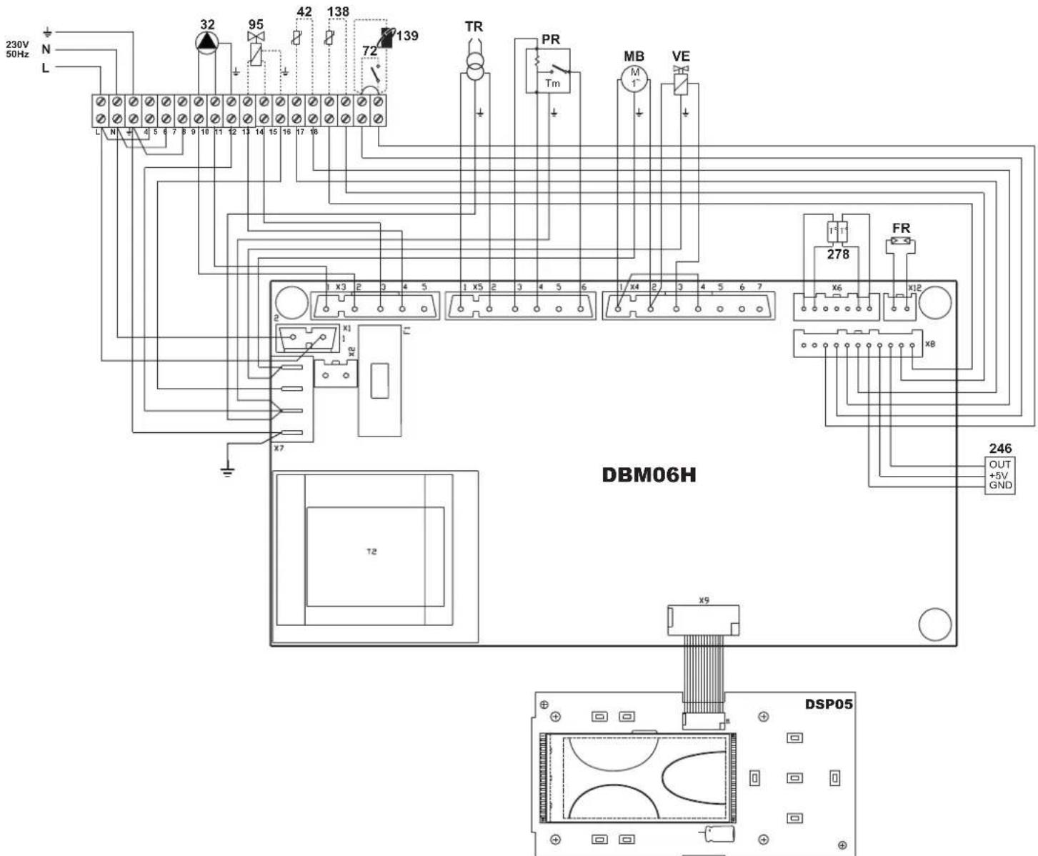
fig. 52 - Wiring diagram
32 Heating circulating pump
42 DHW temperature probe (optional)
72 Room thermostat (optional)
95 Diverter valve (optional)
- Powered (230 Vac) = Heating position
Not powered = DHW position
138 External probe (optional)
139 Remote Timer Control (optional)
246 Pressure transducer
278 Double sensor (Safety + Heating)
TR Ignition transformer
PR Preheater
FR Photoresistance
MB Burner motor
VE Electromagnetic valve


fig.28-Evacuation condensation
Tableau 7 - Indications led circulator
1.2 Bedleningspaneel
Paneel<
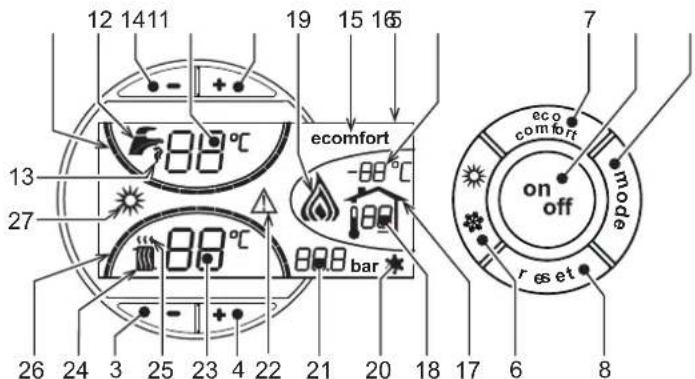
fig.1 - Controlepaneel
Legenda paneel
Sanitair water (Comfort)
Uitschakeling boiler (economy)
Egapiepn mroiaep (economy)
O xipntnc mtopei va diakoei tn thepuavan/diatnpn on nts eepokpaaic tou mioiep. Tnv tpiwn autn dev utapxeyi npaywyn cetou vepou xpns.
Oav n 6epaovon Tou mIoep elvai evpyn (Tpoetnioyn), oTIV oOvyn elvai evpyo to oUBOLO COMFORT (AeTTIOU. 15 - EK. 1), eVvOtavai aTeVEpyoToInJeuN, oTIV oOvyn evpyoToeiTA to OuBPO ECO (AETTI. 15 - EK. 1)
To tiolepe npoei ve atteevytoinoei to xpnnt (eitoupyia ECO) natovac to koujti eco/comfort (eTT. 7 -Eik. 1). Ia nve evytoinon TcI eantoupyiac COMFORT TATOTET EK VOU TO KOUJIeco/comfort (eTT. 7 -Eik. 1).
1.3 Evepytooinn kalteevpoytoinon
AeBntasXwpiis nEkrptiKt troofooio
EIK.4-AeBntaXwipnnaektpknTpoopooia
AiaKoTTovTac TnV TpoOoOia nAekTPIKOU peuatoC n/Kai aepiou Tns OuaKEuNC,TO ouoTma TPOoTAoIAC aTo TO PAYeTO DEV LEIToupyei. Ia va aTPOeUxOouv BALAEc Tous OpeiIoAVtai OTOV PAETO e Eeyalec TEPIOOUs biakOtnc xPnOg To xeiuWva, Ouviotatai n EKKevwOn oAou Tou Vepou aTo TO AEBnta, too Tou Vepou oIKiAKNc xPnOng 000 KAI TOU VEPou TNS EYkATAOtaOns. DIApOpETiKa, Ouviotatai n EKKEVWOn MVO Tou Vepou oIKiAKNc XPnOng Kai n TPOoTHKn EIDIKOU AVTIuKTIOU OTNV EYkATAOtaOn Thepavonc OUMFWVA ME TIG ODNyIEc OTN SEZ.2.3.
EvpyoToInOnn Aebnta
AvolTe Tg BaBldes biakOnns Taopxns KaouJou.
SUVDEOTIoukeun OTNVnAekpiKnpoobogia.
EIK.5-EepyoToiOnnAeBnta
Sigma ETEUVEA 120 DEUTEPOLETTA, OTO TAVW MEPOCS aOVOV cEAPAVCEaI eEvdeiE FH TOU UTODEIKVUEI TNY KKTAEON TOU KUKLAOU EEAePwON TC Nc EYKAATAOANC 8epauvAnS.
Sta 5 Pwota deutepoAeTTA, eupavicTai EIncS OTo KAtu Tnua Tns OboVnc n Ekoon loyioikou nTn NkAeTas.
Otaatapnai evaepavicetai nEvbeiH F, oEbetaac evai Etouc yiautoaetaeupyia kabe pao TnXPnoiotoeiTceto Vepo iokianxpnans divetaievtol an toeepoataxwpu.
ATEVEpyOToina λβητ
PntnoTe To Koupti on/off (AETT. 9-EIK.1) yia 1 EutepeoAETTO

EIK.6-AntevepyoTOnn Aebnta
Otav aTepepyoToiOnBei o AebnTac, n naektpik npopooia Tns naektpovikns taaketac ouvexicai.
ATVEpyoTIOeIa n aeioupvia vepou oikiaKs xipnks kai bepuvans. Napapeve I Epeytoiuevo to ouatma npoataiaac ato tv naet.
Tia va evepytoietae 5aVa to aeBnTa, TATnate kai taI To Koupi on/off (AETTT.9 EIK.1) ia 1 eutepeoAeTo.
EK.7
O Aéβηtrac éivai eioiouc yia ayean aeitoupyia kαθe φρa triu xρnoiμtonoiitai ζeotovp oikänkx pniangn idivatnEvtoan to Bepoostatn xwpou.
1.4 Pubuigeic
Emoyn 0epivns/xeiueepivns aeitoupyias
PnTnote To KOUPTI eepivic/xeiuepivics aeitoupyias (AETT.6-EK.1) yia 1 EeutepeLTTo.
EIK.8
Awaioyko maovotepiko uoos p-v
Teaepo maovopetpkó uos p-c
Sigma
EvEeig Etnyuevns xaoaikmpoianKKaumuans 1 ,2 ,3
I vO S TOU pOToU pOToHnS
SuvouaTikcEvEeieuAUXwGLELDKATAIaENoupyiaEeaepoongtou Kukaoopopyn, TxepokivnETTROVEKKIVNpKai ToKaEoiWQAoumIO
Eevnnte to koumtl mptelte va pubaetote touk dappoocu ouvuaoupou poun
Eav to natoe via 3 deutepoAetia, evpytoioi ta n Aetoupiy
Eav to taoe fo 5 eepoAETTA, npayatotooiE xepoknTt eravekkyn
EAV TO TIOIHOETE YO 8 EUTEPOAEETRA, KAEISWVEIgKAEIDWVEI TO KOUPTI
Tia ootao tnteaejou tou uoloyiouu Ioouyu 0epukns pnootnac (β λ) evotna 1I OZYIO OEPIMKHE NOSOTHTA2 (KATAOXPIH), o kukloopnptnc Tp va exei puoiote ot nteitoupyia Etaepoc apioos opoov Kai otn Bcn . Tia va ekeetaeate autyntu pueoiian, tnatotie PAAe, opeoc to koupti Aexpi v avayouv oi auviic LED TIO paivovtai OTnv Tnapakatw Eikova.
Xapaktnpiotka tou vepou tns eykatataoans
Eav n okknptnta Tou vepou tnc ykataotaanc utepbaivei touc 25° Fr (1°F = 10ppm CaCO3), uviotatai n xhon kataanae tceepyaevou vepou wote aantoepueyetai o tiavoc oxnatuaoc atawv toa eBnta. H tteepyaee a th penei va meuvei tn okknpnta oe tiec mikpotepe cto 15°F (π,Δ. 236/88 ia xphoe ievou piocs Katavaow an to tov dovpumoo. Se kae tpepiTuwn, n tteepyaia Tou xpanoiauoivevou evov el attapaintn ekyataaec ieyalanc ektaanc n e ouxve avatianpwaeis Tou vepou tnc ykataataanc.
O tivakac diathe 20 napapetpouv Tou ptoopoov va TpoTOnToHouv kai ato to nExeiptipio (Mevou epeBic).
TATWYAC ta KOUMTI BepaVAnC, MTPOEte va METAKINthe Tn IAta TAPaTePua Ue auoua nΦthoua oepia. Vp TaTOPTOInoAe Tm NIm ia TAPaETpu, TIPeTeVa TATHOte ta KOUMTI vepou iKIAKNS XphonC: nTOPTOInoAToTHKeUeTaAutaOpA.
AAaTe Tny TnapaETPO 02 TOU Mevou Tapaepwv 6
Tia va EITiTpEeTe OTo Mevou eepBic, TATnATE To KOUmTI EITavaopopa. Ia efo 0to MeVou eepBic TOU nIvaka, TpETeVA TATnOe To KOUmTI EITavaopopa. Yia 10 DEUTePOAETTA.
8
9
A
EIK.20
Otoo, mopeite va putheta e diapopetikto tpo taioupyiac avaoa µ ta xapaktipitka tsykatataans.
-PuOuian p-v aVauoyikou mavouetpiokou 0ouc
To yapovetpiok uosoc tou kukloopnnt tha eiwthetaautopata otav eiwtheta nnapoxnou atanatei ato tv evkataotaon.
Ta TIAEVOETJMAI EAVI N JELIOW TNC N KKTPIKNG KATAVALUANG OTAV MEIWEI N GNTN TNS EYKAATAOANs KA I EIWON TOU OTOBPOU. To EUPOCS LEITOUPYIAKUAIEVATAI ATN TY EAXAIXT WECN T MEOIIN TNI.
-PuOiO p-c Oaepou aavoetipkoU uyous
To avoetpiok uoc Tou kukopopnT npauevei oaepe otav eataaenei npox Tou aaiteirai ato tv Eykataotan.
OeOnnAeKtpoBiw-BiaqpaayatoS
Meta TNYTOTOBENIOTU μTKE, ELEYE TE OAWTNTOTOEETN TUV NAEKPOBIW KAI TOI 11aipaypatoc ouPwovA TE TAPAKATOWIc. Suviotata O AeyxosT W TIVW M TaO kabe ETIEBaON Tny KEpaH
3.2 QeON OE Aetoupyia
'EAeyxoi TOU PPeTI VA EKTALOUVTAI KAa TIV TIPwTN EVpyoTIOJOn, KaWc KAI eTAtro EpyaOIEC OuvtnpOAnG YIA TIG OTIOE CATAIeITAI aTOOuVDeON TOW OuaTnmuTsw n ETEμBaON OTA opyava aOgAaleiac n OTA EGApTnpuTau LEBNTa:
Pivavoveto λeβητα
AvoIeTc Tc EvexoEvcs BaJIbEs dakottns metaU aeBnta kai EykaataoaeWv.
ELeyTe Tn OteyavotntaTc Tng EYkataoTaon Kaouou.
EeYTe Tn Owtn PpOPOTIOI TO DOxeiou DiaToA
F EJIaIe Tn U6paAunikvEYkataOaon Kai BepaWBeite yia Tny TAnp EaePwOn Tou aepa Tn TepiExei OlambdaTc Ka n EYkataOaon AoviovVtac n BaAlbda Biaqpyns aepa Tn ElambdaTc Ka Tc Evxoepeves Baalbdes Eaepuwns Tc NkEATaOaons.
Beaiwthei 10vI auXovuapooce vpu oTny evkataaon, ota kukawata vpu xphnc, otc suvdeoeic n oto Aebnta.
BaeiWthe iay niouwn ouveon nnc naekptikc Ekyataoans kai yni atoteaepatikotntn cyselwng.
Bbaowte otov npxouv eukkta uypa nukov ta oAeeta.
TOTOBETNTOA JAVOJPO KAI TO KEVOpTeo ATNv AVTLia Tou KAUATnPa (aapaipeTe Ta tegT In Theon Oe Aeioupyla).
Avoigt Tis Baveos OTouc oWAnveTou TETpeAiaou
Evauon
EIK.37-EvEpyoToin
A
OaV Kaei ngepooatnynpaun, o kivntnpac tou kauotnpa tibetai oe aeitoupyia paqi me tvavta: to ttepeiaio ncs avapopqnns onoynelai oao npoc nvy eitipopn. Aetioupyov EETION O avepiatnpac tou kauotnpa ka o paaanpatnc evauanc kai kata ouvetieia kctekouvtaoi o poaeic
TPOeEaepiooC ts Eaia
PpOuOgEvOgTuKkWpatOgTepaioU.
TPOaVapalegncEeKkewwn eTaTuWakpWtWnAektpoivw.
B
TeAos Tns TpOAnOs O IVaKaE Aevxou avolye TnV nAeKtpoayvnti KaBla: to TETpeAio QTaeI OTo MTek aTo TOtolo Yekacetai.
H eTnEe Tnv EKevwn PeaTu wv NektpodiWv POKaEI to oxnuaioo nC oovac.
Tauroxpova, apxiEIO xpovos aepaaleas
Kuklos ouakeun
EK.38-Kuklos ouokeuins
R-SB-W ΕεμοστάτεςΠεδοστάτες
OH Ppoepmuavnpa nTpeaaifou
OW Etnaipn eEyxou aeitoupyia
M Kivntnpac kauotnpa
Z Metaoxnpatiotnc evauonc
BV Hektpoayvntik β λ βiδ
FR
A' EvapgEvauonG ppoepmuvtnpa
A Evapg envaunx wpi npoepaavnpa
B Napouoiαλoγα
C OuaHn Aetoupyia
D Naouonpuθμiσns(TA-TC)
t1 Xpovoc TpoeEaepiou
TSA Xpovoc aopaaieas
t3 Xpovoc npoavapAeEns
t3n Xpovoc µ τανα
tw Xpovoc ppoepmuavong
Σηματεξόδου αποτον πίνακα
∑nua aaykala stny eioo
EeYxo kata th diapkeia tns aeitoupyias
Avayte Tn ouakeun ouuowua e Tc obnye cTny sez.1.3.
BebaiwBeite yia n oteyavotnTa Tou kukkwpatoc kaoumuou kai twv eykataotaeewvepou.
EAEyTE TnV aTIOoON TNS KAIVADaC KAI TOW V ayWyyw aepa-kaUOaepiW ME To AEBNTa OE AIEIoupyia.
Beaiwtheire yia in oawtn kukloopopia tou vepou oto λeβnta kai otic eykataotaeic.
EAEYETn OWTNI AEIOUPVIA TOU AEBNTI PPAYATOTIOAVTAC OPIOVEC 0KIOEC evauoN KBI OINIATOC MEOW TOU BEPPOATN TEPBAALOVTO N TOU EIGTEPIKO XeipiTNIPIOU.
ELeyTe Tn Oteyavotnta TnTnpTaou KauoTpa KaI Tou Balaou Kauoaeplw.
Bεβαιωθείe οτο καυστήραςλειουργέι σωτά.
EKTAEOTIa avauon ts kaounO (e To λebnta staepooinuevo) kai βepaowtei 0TI TOIOOOTO CO, OTA KAUaaepia Kuaivetai ano 11% EwC 12%.
EAEYETO OAWOTIPOypaumiaoTOUVTAPaETPWKAI EKTEAEOTUXOVavaykaie TPOOWNIKEspuHIOIEG(KaUMNAnVNTATBIOIg,IOXUS,EPouOKpaoiesK.AT).
3.3 Evvtnponn
πepiδikos λεγxos
Tia va eEgapalicietai n owtn aeitoupyia tnc oukeuins me tvnpodou xpvou, ta TPTeirva aovabece de EeEieikkeuve Ptooowtko to Etioo epic no Ta PtoaPaeTeIO Touc AokolouBocEAEYXOC
Ta ouotnmuata xeiipaoou kai aopaaieac PpTei va aeitoupyoov owaTa.
To kukawga aattaywyng twv kauaepiw npetie va aeitoupye tEia
Bbaowte 01 o wlnves tropooboc kai eioptpohc kaouou dev evai Bouluevoi kai dev exouv xutnmuata.
Kaaiote to pIATPO TnS ypaunC avappnoTou kauipou.
Metphote tn owath katavawon kaouipou
Kaapate nV Keapn KaanC atn Zwn Eoo Tou Kaouou, oTo biako 0tpoiaou.
Aphote Tov kauotnpa va aleitoupyne ie t n meviot ioxy eti deka lettta tepinou KAI OTN OUVEXIA AVAUte ta kauoepia ia va ekyete:
Tis oowotc puoipieic oawv wv toxieiw Tou npiypapovtai oto npov Eeyxepio
Tic 0epuokpaoies tw kauoapeiw otny kaivaba
-To TnoooCo2
Oi ayyoai kai to Teppatiko aepa-kaauaepiw npetie va eivai euehepoia ato Emuia kai va mny napouotaoov diappots.
O KaUToIpaC KAI O evAAakTc TpTei VA EIVA KAbaoi KAI EAEUBepoi ATOAaTA. Ia To EvExoMeV KOaipoiO np XpnaiotIOeITE XnmuKia TPOIOvTA n ATAOIAVECS BOpTOE
Olyekataotadaeic kauooukai vepou Tpentei va eivai oteyavec.
H niocn Tou vepou e Tnv Ekyataoan Kpua npetra va evai npitou 1 bar. avtBttn nepittwn npetra va nv enavapepe ae auty tv tni.
O Kukaoopopnns 6ev TpeT eiv aiv aiaokapiaevoC.
To doxio diaoToAns npenv aivayeepato.
EAEyTe TnV avoOaaynoIou kEv avayknavtikataotneTnV.

Tia tv TIAVIO KABAPIO TOI PEPBAAHATOC,TOU NIVAKA KAI TOW BIAKOJNTIKUVO ATOXIEUV TOA EJIHTa UTOPEITE VA XPOIOTIOEETE EVA MAKOK KAI UVPVTBIPEYEV OVEQYEWEO SE DIAUMA ME ATOPPUTAVIKO. PENTI VA ATOPEUYOVTAOA TDAIBPWTIAATOPPUTAVIKO KAI DIAULTEC.
Pp6oBaaon 0To nAekTpodio kai 0To pTtEK
Atoouvde ta kalwia tuv nektpoiwiu tou metaoynnatiotn kai apaipeote tn qutoavtioaon 1 kai to pakop 2 tou ouvseei to ownaTETPEAIou OTypaui 3 Tou uTK. Xaalapowte Tc BiEc 4 KAI apaipeote To ouoTnua qAvvtacmTEKdiappayatoc-naktpoiwiw.
EIK.39
EbiowTe Tbi0a 5 ia va apaipeeteto diappayka kai tn bi6 yia va apaipeeteto naekpobia. KaacKaapaiocou Tou ttek EENTUYXavetau pe apaipeon Tou pfalpou, KaepapioTuw EKOTWv KNTc OTNtpsiKaaou je BeVcnk AETLua. Kata nTv EtavatoTOBENn OAWv Tu aOteiWv, antaeiTn PPOoxn otwn ToTtoBttnoTuv NkEkpodiWv-Tou diaqpayatoc.
EIK.40
KaopioosAeBnta
- AnouvOeTo λεβηTa απo ην Λεκτρικ Tpopoδoσia.
- Apaipoe TOV Kauo npa oTWC Tepiypapetai TapaTavw
- ApaipoteTOUS IVAKES EKAI FF EBiowovTAsOxETIA
- KaBaplate To eouteipko Tou Aebeta Kai ooknpn Tbiapoun Twkauaepiw Xpnootowrtos Boptoc nTETeouevo aepa.
- KAEIOTE TOU TIVAKEC
Kaepiopocouoatmuosavaktnonkaaepiwv
Tia tov kaabapioo tou ouatniatoa avaktnnks kauaaepiw TpTei va:
Apaipate To Kattaki B
ApaipoeTe Ta kattakia kleiojatoc C Tou ouotmuoc avaktnnc kauoepiwv.
XpooiotoiovtacnAekpiKooutaKaBapite PPOeKTiKaTO eawtepko Tou auTmuatocavaktnang.
Eav utapxouv noaies akabapieis, mtopei va xpoiooitnoe tia kataan an oukeun yia ekaov oevp oTo eotwepikoi. Tny npiipttwn autn, attariteai ibaitepn npooyn wote va atopveuxei n etapn neyalnc troootntac vepu me ta otoixeia ato utooipno oTo dalaqau kawaeipvi. Apnrote to vepva tpeelieu wtnc eaywnsouittkuvmatoC d apov atouuvseetoe to opovi.
EK.42-KaBapiooosouotnatoacavaktnons
TOnToBcTeHnXTeVivv
Metavot katoo tou ouatnatoos avaktnons, pteie va bebaiote et on ta xevia exouv totoe tneoiota otwc atowc palvatai otyn Eik. 43. sice ta taoiaodia otepuwong odo kao soumtiet A) peoitn ouoigns 0,6 Nm. Eaov eexte duvaopetko kleiidi, beaiote on n diieueon twkauoeipwu metae uot oeipw eviai 1 mm.
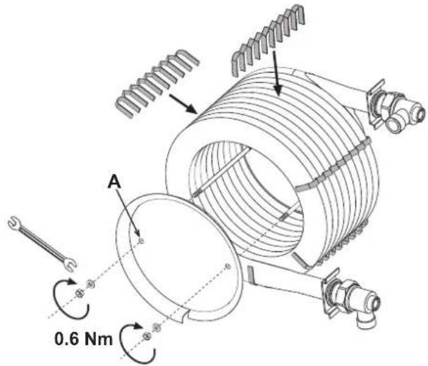

EIK.43-TOTTOBETONXTEVIW


- OPERATING INSTRUCTIONS
- Introduction
- Control panel
- Panel key
- Indication during operation
- Heating
- DHW (Comfort)
- Exclude hot water tank (economy)
- Lighting and turning off
- Boiler lighting
- Turning the boiler off
- Adjustments
- Summer/Winter Swithover
- Heating temperature setting
- DHW temperature adjustment
- Room temperature adjustment (with optional room thermostat)
- Room temperature adjustment (with optional remote timer control)
- Sliding temperature
- Compensation curve and curve offset
- Adjustments from Remote Timer Control
- Water system pressure adjustment
- INSTALLATION
- General Instructions
- Place of installation
- Plumbing connections
- Important
- High efficiency circulating pump
- High-efficiency circulating pump (model PARA)
- Water system characteristics
- Antifreeze system, antifreeze fluids, additives and inhibitors
- Connection to a storage tank for domestic hot water production
- Burner connection
- Electrical connections
- Room thermostat (optional)
- Accessing the electrical terminal block
- Connection to the flue
- Condensate drain connection
- Conversion of boiler with burner to sealed chamber (only version ATLAS DECO 34 COND UNIT)
- Connection with separate pipes
- SERVICE AND MAINTENANCE
- Adjustments
- TEST mode activation
- Burner adjustment
- Pump pressure adjustment
- Combustion head adjustment
- Air damper adjustment
- Position of electrodes - baffle
- Commissioning
- Before lighting the boiler
- A
- B
- Checks during operation
- Maintenance
- Periodical check
- Accessing the electrode and nozzle
- Boiler cleaning
- Cleaning the fume recuperator
- Positioning of combs
- Troubleshooting
- Diagnostics
- ATTENTION
- Circulating pump diagnostics
- Circulating pump diagnostics (model PARA)
- TECHNICAL DATA AND CHARACTERISTICS
- Diagrams
- Technical data table
- ErP product fiche
- Wiring diagram
- Bedleningspaneel
- Legenda paneel
- Sanitair water (Comfort)
- Uitschakeling boiler (economy)
- Egapiepn mroiaep (economy)
- Evepytooinn kalteevpoytoinon
- EvpyoToInOnn Aebnta
- ATEVEpyOToina λβητ
- Pubuigeic
- Emoyn 0epivns/xeiueepivns aeitoupyias
- EIK.20
- OeOnnAeKtpoBiw-BiaqpaayatoS
- QeON OE Aetoupyia
- Pivavoveto λeβητα
- Evauon
- EeYxo kata th diapkeia tns aeitoupyias
- Evvtnponn
- πepiδikos λεγxos
- Pp6oBaaon 0To nAekTpodio kai 0To pTtEK
- KaopioosAeBnta
- Kaepiopocouoatmuosavaktnonkaaepiwv
- Apaipate To Kattaki B
- TOnToBcTeHnXTeVivv
Brand : FERROLI
Model : Atlas D Eco Cond Unit
Category : Boiler