
TP3 LN - Boiler FERROLI - Free user manual and instructions
Find the device manual for free TP3 LN FERROLI in PDF.
| Brand | Ferroli |
| Model | TP3 LN |
| Type | High-efficiency three-pass flue gas boiler |
| Fuel | Oil or gas |
| Nominal power (kW) | 70 - 2360 (depending on model) |
| Firebox power (kW) | 48 - 2450 (depending on model) |
| Max operating pressure (bar) | 6 |
| Dry weight (kg) | 236 - 4041 (depending on model) |
| Dimensions L x W x H (mm) | 670x770x1116 to 1340x2998x2371 |
| Flow/return connection | 2"1/2 to DN200 |
| Flue gas outlet connection (mm) | Ø160 to Ø500 |
| Burner connection (mm) | Ø145 to Ø350, nozzle length 250-480 |
| Safety connection | 1"1/2 to DN125 |
| Condensate drain | 3/4" to 1"1/2 |
| Main functions | Three-pass flue gas, wet combustion chamber, turbulators, fiberglass insulation, painted steel cladding, adjustable door, control panel (optional) |
| Maintenance | Periodic cleaning of flue tubes and combustion chamber, replacement of seals, combustion check |
| Safety | Safety thermostat, safety valve, expansion vessel |
| Certifications | CE (compliant with GAR regulation) |
| Warranty | Subject to proper installation and maintenance conditions |
| Target countries | ES, IT, FR, RU |
Frequently Asked Questions - TP3 LN FERROLI
User questions about TP3 LN FERROLI
0 question about this device. Answer the ones you know or ask your own.
Ask a new question about this device
Download the instructions for your Boiler in PDF format for free! Find your manual TP3 LN - FERROLI and take your electronic device back in hand. On this page are published all the documents necessary for the use of your device. TP3 LN by FERROLI.
USER MANUAL TP3 LN FERROLI
High-efficiency boiler for liquid or gas fuels
INSTRUCTIONS FOR USE, INSTALLATION AND ASSEMBLY
INSTRUCTIONS D'UTILISATION, D'INSTALLATION ET DE MONTAGE
TEXHnueCKnIACNOPTN3JIINr
PYKOBOCTBO IO 3KCIYATAUIM,MOHTAXUYTEXOBCJYXUBAHIO
4.1 Description of the appliance 31
4.2 Operating principle 32
4.3 Technical data - Dimensions - Hydraulic connections 33
4.4 Identification 34
- INSTALLATION 34
5.1 Packaging 34
5.2 Handling 34
5.3 Boiler room (Fig. 5) 35
5.4 Discharge of combustion products (Fig. 6) 36
5.5 Hydraulic connections 36
5.5.1 Supply water 36
5.5.2 Central heating outlet/return pipes 36
5.5.3 System fill/drain pipe 36
5.5.4 Pipes, expansion vessel and safety valves 37
5.5.5 Recirculation pump (Fig. 7) 37
5.6 Opening and adjusting the front door 37
5.7 Assembling the burner (Fig. 9) 38
5.8 Connecting the flame inspection window (Fig. 10) 39
5.9 Assembling the panels, models 92÷ 190 39
5.10 Assembling the panels, models 240÷ 2360 40
6.COMMISSIONING 41
6.1 Preliminary checks 41
6.2 First ignition 41
6.3 Shutting down the boiler 41
7. MAINTENANCE 41
7.1 General instructions 41
7.2 Routine maintenance 41
7.3 Special maintenance 42
7.4 Cleaning the boiler 42
7.5 Checking boiler operation 42
7.6 Checking burner operation 43
7.7 Troubleshooting 43
1. INTRODUCTION
Dear customer:
Thank you for choosing a TP3 LN boiler. This manual was written to provide information, warnings and advice on the proper installation, use and maintenance of the boiler.
Please read it carefully and save it for future reference. It is in your own interest to carefully follow and observe the instructions given in this manual, in order to fully enjoy this high-quality product.
Failure to comply with and observe the instructions contained in this manual exonerates the manufacturer from all liability, and invalidates the warranty.
2. GENERAL WARNINGS
- The instructions manual is an integral part of the product, and provides a description of all instructions that must be observed during the installation, use and maintenance phase.
- This appliance must only be used for the purpose for which it was expressly intended.
This appliance is intended to heat water to below-boiling temperatures at atmospheric pressure, and must be connected to a central heating and/or domestic hot water distribution system, in accordance with its characteristics, performance, and heat output. - Before installation, check that the boiler has not been damaged during handling and transport.
- The boiler is to be installed on a non-combustible base.
- The boiler is to be installed with a distance of at least 100mm to any combustible material or component.
- The installation must be performed by duly qualified personnel, in accordance with current standards.
- Before performing any cleaning or maintenance operations, unplug the appliance from the mains power supply.
- THE MANUFACTURER is not liable for any damage to people or things due to errors in installation, adjustment, maintenance, or improper use.
- The boiler and corresponding system must be commissioned by authorized personnel.
- Commissioning is performed in order to verify proper operation of all adjustment and control devices.
- Qualified personnel must be contacted if the appliance is not used for an extended period.
Standards
The installer must observe current local regulations with regard to: the site chosen for the installation of the boiler, compliance with required ventilation conditions, the tightness of the connection to the chimney, connections to fuel lines, electrical systems, and any other relevant safety standards.
Warranty conditions
The warranty is only valid if the standards and recommendations for use contained in this manual are observed. Any non-compliance or modification will void the warranty. The warranty does not cover damage caused by acidic condensate corrosion from the products of combustion, or the formation of deposits caused by the use of hard or aggressive water, as these are caused solely by system operation.
3. CERTIFICATION

The CE marking certifies that the products meet the essential requirements of the GAR regulation and other applicable directives. The declaration of conformity may be requested from the manufacturer.
PRODUCT IDENTIFICATION CODES
4.1 Description of the appliance
The construction of the TP3 LN series boilers guarantees high output and efficiency at low flue gas temperatures, thus ensuring reduced polluting emissions. The appliances are made according to the EN 303 standard, part 1.
The main technical elements of the design are:
- the careful design of the shapes, to ensure an optimum ratio between the combustion volumes and the heat exchange surfaces
- the choice of materials used, for the long life of the boiler.
The boilers use pressurised combustion, with three flue passes, overlapping double plating with completely cooled furnace on the bottom part and the tube bundle on the top part, and featuring turbulators to create a swirling path that increases the heat exchange by convection.
On leaving the tube bundle, the flue gas enters the rear chamber and is transferred to the chimney.
The boilers are fitted with a door featuring hinges that can be reversed for opening to the right or the left, and is adjustable in both height and depth. The body plating is insulated with a thick layer of glass wool, and covered with a further layer of tearproof material. The external finish consists of painted steel panels. The hoisting hooks are fitted on the top of the plating. The boilers feature two 1/2 fittings for bulb sheaths (able to house three bulbs each). The pre-wired control panel (to be ordered separately) is located above the boiler, and ensure automatic operation.
4.2 Operating principle
The TP3 LN boilers are fitted with a closed cylindrical furnace, in which the flame produced by the burner is reversed peripherally towards the front, from where the burned gas enters the fire tubes. At the outlet, the gas is collected in the smokebox and is then sent to the chimney. The combustion chamber is always pressurised during the operation of the burner. For the pressure values, see the tables on page 16, under the column Flue gas side pressure drop. The flue and the flue stack fitting must be made in compliance with the standards and the legislation in force, using rigid pipes that are resistant to high temperatures, condensate and mechanical stress, and are airtight (Fig. 1).
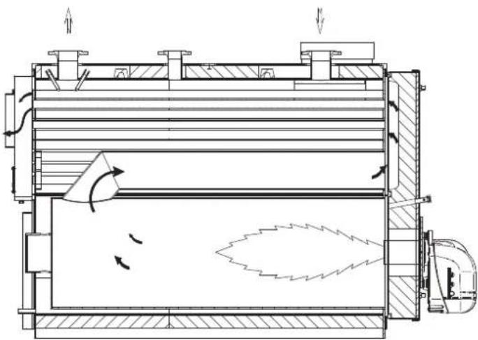
fig.1
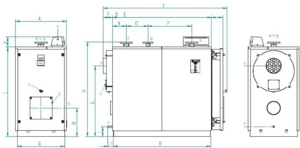
fig.2
Key
1 Control panel T2 Water return
2 Burner mounting flange T3 Expansion vessel connection
3 Smoke box cleaning door T4 Discharge/exhaust boiler
4 Flame inspection window T5 Chimney connection
T1 Water delivery T6 Burner connection
4.3 Technical data - Dimensions - Hydraulic connections
| TP3 LN 70 92 107 152 190 240 320 401 500 | |||||||||||
| Heat output | min. kW 46 60 70 100 137 160 196 260 341 | ||||||||||
| max. kW 70 92 107 152 190 240 320 401 500 | |||||||||||
| Heat input | min. kW 48 62,7 73,2 104,7 143,8 167,8 205,2 271,5 354,6 | ||||||||||
| max. kW 73,9 97,1 112,9 160,5 200,8 252,9 335,7 419,4 522,8 | |||||||||||
| Water side load. loss | Dt 15°C | mbar | 6 | 6 | 12 | 7 | 10 | 17 | 23 | 22 | 28 |
| Flues side load. loss | mbar | 0,54 | 0,89 | 1,2 | 1,65 | 1,8 | 2,4 | 3,3 | 4,4 | 5,43 | |
| Flue gas flow-rate* | kg/h | 119 | 156 | 182 | 258 | 321 | 405 | 539 | 670 | 838 | |
| Max operating pressure** | bar | 6 | 6 | 6 | 6 | 6 | 6 | 6 | 6 | 6 | |
| Weight 6 bars standard | kg | 236 | 236 | 332 | 332 | 460 | 524 | 833 | 833 | 1146 | |
| DIMENSIONS | A | mm | 670 670 | 670 670 760 | 760 820 820 | 855 | |||||
| B | mm | 770 | 770 | 1190 | 1190 | 1190 | 1390 | 1590 | 1590 | 1990 | |
| C | mm | 1116 | 1116 | 1116 | 1116 | 1271 | 1271 | 1456 | 1456 | 1546 | |
| D | mm | 165 165 | 165 165 165 | 165 165 165 | 165 | ||||||
| E | mm | 146 146 | 146 146 165 | 165 184 184 | 184 | ||||||
| F | mm | 152 152 | 152 152 152 | 152 152 152 | 152 | ||||||
| G | mm | 880 | 880 | 880 | 880 | 985 | 985 | 1140 | 1140 | 1225 | |
| H | mm | 390 390 | 390 390 420 | 420 460 460 | 480 | ||||||
| I | mm | 1130 | 1130 | 1555 | 1555 | 1570 | 1770 | 1990 | 1990 | 2390 | |
| M | mm | 160 160 | 160 160 145 | 145 160 160 | 155 | ||||||
| ATTACHMENTS | outlet | T1 | 2" 1/2 | 2" 1/2 | 2" 1/2 | 2" 1/2 | 2" 1/2 | 2" 1/2 | DN 80 | DN 80 | DN 100 |
| return | T1 | 2" 1/2 | 2" 1/2 | 2" 1/2 | 2" 1/2 | 2" 1/2 | 2" 1/2 | DN 80 | DN 80 | DN 100 | |
| safety devices | T3 | 1" 1/2 | 1" 1/2 | 1" 1/2 | 1" 1/2 | 1" 1/2 | 1" 1/2 | DN 50 | DN 50 | DN 65 | |
| discharge | T4 | 3/4" | 3/4" | 3/4" | 3/4" | 3/4" | 3/4" | 3/4" | 3/4" | 3/4" | |
| flue gas outlet | T5 Ø mm | 160 | 160 | 160 | 160 | 220 | 220 | 250 | 250 | 300 | |
| burner connection | T6 Ø mm | 145 145 | 145 150 150 | 150 240 240 | 240 | ||||||
| min/max draught tube length | T6 | 250/320 | 250/320 | 250/320 | 250/320 | 250/320 | 250/320 | 250/320 | 290/360 | 290/360 | |
| TP3 LN | 600 | 720 | 820 | 940 | 1060 | 1250 | 1480 | 1890 | 2360 | ||
| Heat output | min. | kW | 390 | 468 | 533 | 611 | 689 | 813 | 962 | 1229 | 1535 |
| max. kW | 600 720 | 20 940 1060 | 250 1480 180 | 2360 | |||||||
| Heat input | min. | kW | 403,8 | 484,8 | 552,3 | 633,4 | 714,5 | 843,7 | 999,1 | 1278,1 | 1598,9 |
| max. | kW | 627,2 | 752,5 | 856,7 | 981,6 | 1106,3 | 1303,6 | 1542,0 | 1919,3 | 2449,8 | |
| Water side load. loss | Dt 15°C | mbar | 18 | 25 | 25 | 33 | 40 | 55 | 45 | 70 | 65 |
| Flues side load. loss | mbar | 6,2 | 5,9 | 6,7 | 6,3 | 7,2 | 7 | 7,4 | 7,2 | 7,8 | |
| Flue gas flow-rate* | kg/h | 1005 | 1207 | 1376 | 1574 | 1774 | 2088 | 2474 | 3091 | 3947 | |
| Max operating pressure** | bar | 6 | 6 | 6 | 6 | 6 | 6 | 6 | 6 | 6 | |
| Weight 6 bars standard | kg | 1146 | 1557 | 1584 | 2329 | 2329 | 2601 | 2871 | 3552 | 4041 | |
| DIMENSIONS | A | mm | 855 | 990 | 990 | 1150 | 1150 | 1180 | 1180 | 1340 | 1340 |
| B | mm | 1990 1944 | 1944 2394 | 2394 2594 | 2894 2698 2998 | ||||||
| C | mm | 1546 1791 | 1791 2021 | 2021 2021 | 2021 2371 2371 | ||||||
| D | mm | 165 165 | 165 165 165 | 165 165 165 | 165 | ||||||
| E | mm | 184 184 | 184 206 206 | 206 206 206 | 206 | ||||||
| F | mm | 152 212 | 212 212 212 | 212 212 212 | 212 | ||||||
| G | mm | 1225 1395 | 1395 1625 | 1625 1605 | 1605 1920 1920 | ||||||
| H | mm | 480 530 | 530 600 600 | 575 575 670 | 670 | ||||||
| I | mm | 2390 241 | 2410 2880 | 2880 3080 | 3380 3180 3480 | ||||||
| M | mm | 1615 186 | 1860 2100 | 2100 2100 | 2100 2440 2440 | ||||||
| ATTACHMENTS | outlet | T1 | DN 100 | DN 125 | DN 125 | DN 150 | DN 150 | DN 150 | DN 150 | DN 200 | DN 200 |
| return | T1 | DN 100 | DN 125 | DN 125 | DN 150 | DN 150 | DN 150 | DN 150 | DN 200 | DN 200 | |
| safety devices | T3 | DN 65 | DN 80 | DN 80 | DN 100 | DN 100 | DN 100 | DN 100 | DN 125 | DN 125 | |
| discharge | T4 | 3/4" | 3/4" | 3/4" | 1" 1/2 | 1" 1/2 | 1" 1/2 | 1" 1/2 | 1" 1/2 | 1" 1/2 | |
| flue gas outlet | T5 Ø mm | 300 | 350 | 350 | 400 | 400 | 450 | 450 | 500 | 500 | |
| burner connection | T6 Ø mm | 210 210 | 270 270 270 | 270 350 350 | 350 | ||||||
| min/max draught tube length | T6 | 320/390 | 320/390 | 320/390 | 320/390 | 340/410 | 340/410 | 340/410 | 340/470 | 350/480 | |
- Oil fuel: CO2 = 13% - Gas fuel: CO2 = 10%
4.4 Identification
The boiler can be identified from the:
- Document envelope (1)
This is applied to the door, and contains:
TECHNICAL MANUAL
WARRANTY CERTIFICATE
LABELS WITH BARCODE
RATING LABEL
CONSTRUCTION CERTIFICATE
(certifying that the water pressure tests have been passed)
Rating label (2)
This describes the technical specifications and the performance of the appliance.
It is included in the document envelope and MUST BE APPLIED by the installer, when installation is complete, to the top front part of one of the side panels of the casing, in a visible position. If the label is lost, contact the Ferroli Technical Service for a duplicate.
Tampering with or the removal or absence of rating labels or other means enabling the unit to be identified causes problems during installation and maintenance.
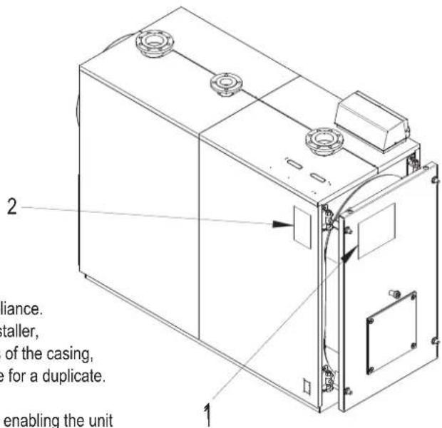
fig. 3
5. INSTALLATION
5.1 Packaging
The TP3 LN boilers are supplied complete with the door and smokebox fitted and insulation on the body, while the casing is contained in a separate cardboard box (Fig. 2). The instrument panel (accessory to be ordered separately) is supplied in a cardboard box and positioned inside the combustion chamber.
5.2 Handling
The TP3 LN boilers are fitted with eyebolts for lifting.
Make sure the hoisting equipment used is suitable for the weight being lifted. Before positioning the boiler, remove the wooden base support by unscrewing the fastening screws (Fig. 4).
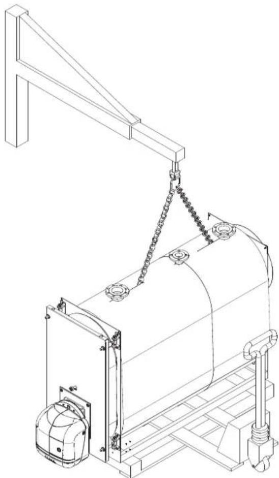
fig. 4
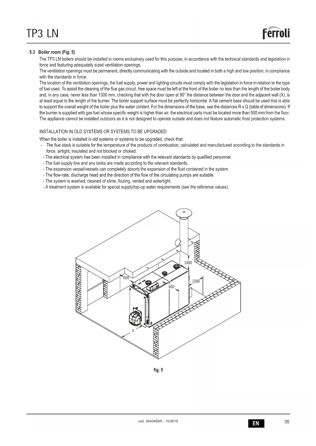
5.3 Boiler room (Fig. 5)
The TP3 LN boilers should be installed in rooms exclusively used for this purpose, in accordance with the technical standards and legislation in force and featuring adequately sized ventilation openings.
The ventilation openings must be permanent, directly communicating with the outside and located in both a high and low position, in compliance with the standards in force.
The location of the ventilation openings, the fuel supply, power and lighting circuits must comply with the legislation in force in relation to the type of fuel used. To assist the cleaning of the flue gas circuit, free space must be left at the front of the boiler no less than the length of the boiler body and, in any case, never less than 1300mm checking that with the door open at 90^ the distance between the door and the adjacent wall (X) is at least equal to the length of the burner. The boiler support surface must be perfectly horizontal. A flat cement base should be used that is able to support the overall weight of the boiler plus the water content. For the dimensions of the base, see the distances R x Q (table of dimensions). If the burner is supplied with gas fuel whose specific weight is higher than air, the electrical parts must be located more than 500mm from the floor. The appliance cannot be installed outdoors as it is not designed to operate outside and does not feature automatic frost protection systems.
INSTALLATION IN OLD SYSTEMS OR SYSTEMS TO BE UPGRADED
When the boiler is installed in old systems or systems to be upgraded, check that:
The flue stack is suitable for the temperature of the products of combustion, calculated and manufactured according to the standards in force, airtight, insulated and not blocked or choked.
- The electrical system has been installed in compliance with the relevant standards by qualified personnel.
- The fuel supply line and any tanks are made according to the relevant standards.
- The expansion vessel/vessels can completely absorb the expansion of the fluid contained in the system.
- The flow-rate, discharge head and the direction of the flow of the circulating pumps are suitable.
- The system is washed, cleaned of slime, fouling, vented and watertight.
- A treatment system is available for special supply/top-up water requirements (see the reference values).
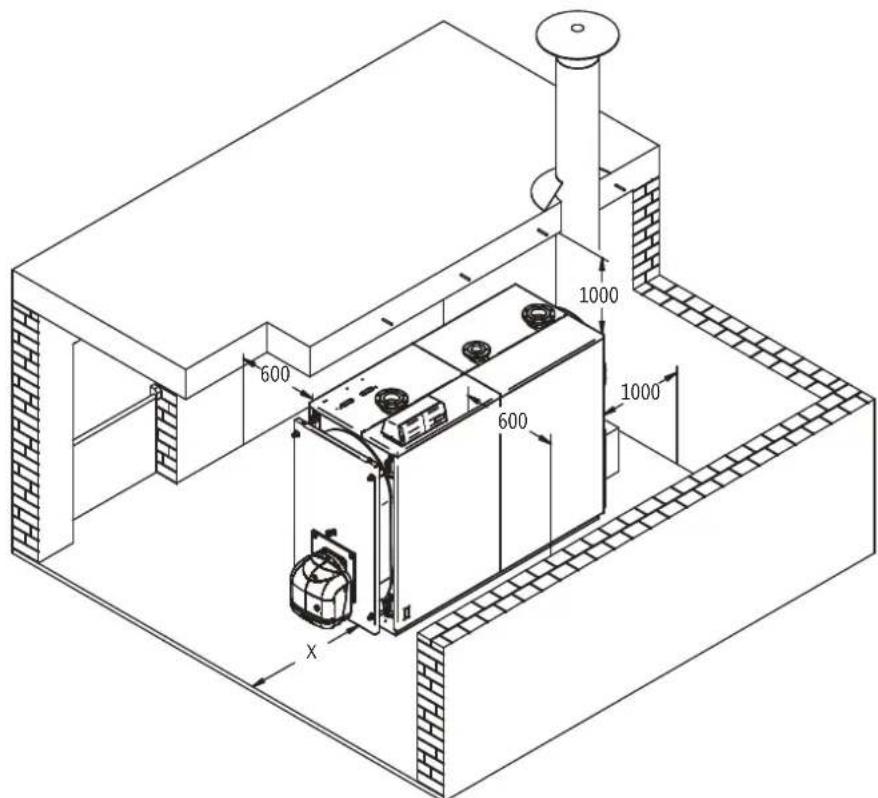
fig.5
5.4 Discharge of the products of combustion (Fig. 6)
The flue and the flue fitting must be made in compliance with the standards and the legislation in force, using rigid pipes that are resistant to high temperatures, condensate and mechanical stress, and are airtight.
The flue must ensure the minimum negative pressure specified by the standards in force, considering "zero" pressure at the fitting to the flue. Unsuitable or incorrectly sized flues may increase the noise produced due to combustion, generate problems involving condensation and negatively affect the combustion parameters.
Non-insulated flues are a source of potential danger. The joint seals should be made using materials that can resist temperatures of at least 250^ . Suitable points for measuring the flue gas temperature and analysing the products of combustion must be prepared in the connection between the boiler and the flue. As regards the cross-section and the height of the chimney, refer to the national and local standards in force.
WARNING: it may be possible formation of condensation inside the stack, because of the low temperature of flue gases.
5.5 Water connections
5.5.1 Supply water
The chemical characteristics of the supply and top-up water are fundamental for the correct operation and the safety of the boiler. The water should be treated using suitable systems. The values shown in the table below can be used as references.
TOTAL HARDNESS ppm 10
ALKALINITY mg/l CaCO3 750
PH8÷9
SILICA ppm 100
CHLORIDES ppm 3500

fig. 6
The water used in the central heating system must be treated in the following cases:
- Very large systems
- Very hard water
- Frequent introduction of water to top up the system.
If, in these cases, the system needs to be partially or completely emptied, it must be refilled with treated water. To control the volume of water automatically refilled, an hour counter should be installed.
The most common phenomena that occur in heating systems are:
- Lime scale deposits
Lime scale tends to concentrate at the points where the temperature of the wall is higher. Due to their low heat conductivity, lime scale deposits cause a reduction in heat exchange to the extent that even when just a few millimetres thick, the heat exchange between the flue gas and the water is limited, bringing an increase in the temperature of the parts exposed to the flame and consequently breakages (cracks) on the tube plate. - Corrosion on the water side
Corrosion of the metal surfaces on the water side of the boiler is due to the dissolution of iron into its ions. The presence of dissolved gases, in particular oxygen and carbonic dioxide, play an important part in this process. Softened and/or demineralised water provides protection against lime scale and other deposits, however does not protect against corrosion. The water therefore must be treated with corrosion inhibitors.
5.5.2 Central heating outlet/return pipes
The dimensions of the outlet and return pipes are shown for each model of the boiler, in the table of DIMENSIONS.
Check that the system features a sufficient number of vent openings. The boiler fittings must not be stressed by the weight of the connection pipes to the system, and consequently special supports must be installed.
5.5.3 System fill/drain pipes
To fill and drain the boiler, a cock can be connected to fitting T4 at the rear (see the drawing of the DIMENSIONS).
5.5.4 Expansion vessel and safety valve pipes
The TP3 LN boilers are suitable for operation with forced water circulation, both with open and closed expansion vessels.
An expansion vessel is always required, to allow for the increase in water volume due to heating.
In the first case, the height of the hydrostatic column must be at least 3 metres above the boiler casing and must have a sufficient capacity to contain, between the surface of the water in the vessel and the overflow pipe, the increase in volume of all the water in the system.
High and narrow vessels are better, as they ensure minimum contact between the water surface and the air, thus reducing evaporation.
In the second case, the capacity of the closed expansion vessel must be calculated considering:
- the total volume of water contained in the system
- the maximum operating pressure of the system
- the maximum operating pressure of the expansion vessel
- the initial pre-charge pressure of the expansion vessel.
The expansion pipes connect the expansion vessel to the system. This pipes that run from fitting T3 (see the table of Dimensions), must not be fitted with on-off valves. On fitting T3, or on the outlet pipe, within 0.5 metres from the first flange, install a safety valve sized for the capacity of the boiler and in compliance with the local standards in force. No type of shut-off device may be installed between the boiler and the expansion vessel, and between the boiler and the safety valves, while the valves should calibrated for activation at values no higher than the maximum admissible operating pressure.
5.5.5 Recirculating pump (Fig. 7)
The condensation of the water vapour contained in the flue gas leaving the boiler (condensate) occurs when the return water temperature is less than 55^ and is significant above all when starting in the morning, after the boiler has been off all night. This condensate is acidic and corrosive and, over time, attacks the metal plate on the boiler. Consequently, a recirculating pump with the function of preventing condensate should be installed between the outlet and return fittings, upstream of any mixing valve.
The pump must ensure, when the system is operating, a flow-rate of between 20 and 30% of the total; it must also ensure a return water temperature no less than 55^ , while the required discharge head is quite low, as it only needs to overcome the resistance of the boiler and the valves. To measure the effective central heating return inlet temperature for the purpose of controlling the condensate prevention pump or managing the functions for getting the system to stable temperature operation, a probe socket must be fitted at a distance equivalent to 3-5 times the diameter of the return pipe upstream of the water coupling.
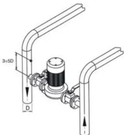
fig. 7
5.6 Opening and adjusting the front door
For TP3 LN models the door is hinged, fastened and reversed as regards the direction of opening as shown in Fig. 8. The following operations are required:
- The door is supplied with four equal brackets (pos. 3) and hinges.
To establish the direction of opening, RIGHT or LEFT, unscrew the nut (pos. 7), unscrew and remove the R or L nut (pos. 6), depending on which side the door opens from.
Height adjustment of the door is performed using the nut (pos. 2); after having completed the adjustments tighten the dowels (pos. 1). - Longitudinal adjustment is performed using the screw (pos. 8).
Key (Fig. 8)
1 Fastening dowel
2 Door support/adjustment nut
3 Hinge bracket
4 Hinge pin
5 Hinge screw
6 Hinge fastening nut
7 Fastening nut
8 Hinge bracket fastening/adjustment screws and nuts
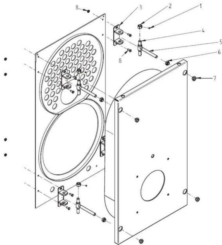
fig. 8
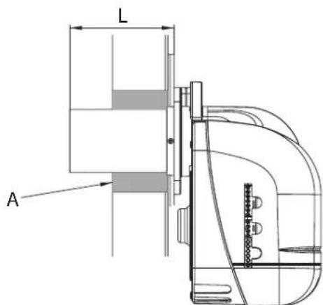
5.7 Assembling the burner (Fig. 9)
The assembly of the burner to the door of the boiler must ensure perfect tightness to the products of combustion. Once having installed the burner on the boiler, the space between the burner draught tube and the refractory material on the door must be filled with the layer of ceramic fibre (A) supplied. This prevents the door from overheating and consequently from being irreversibly deformed.
The fuel connections to the burner must be located so as to allow the complete opening of the boiler door with the burner installed.
| Models L min. (mm) L max. (mm) | |
| 70-152 230 300 | |
| 190-240 250 320 | |
| 320-401 290 360 | |
| 500-600 320 390 | |
| 720-820 320 390 | |
| 940-1060 340 410 | |
| 1250-1480 340 470 | |
| 1890-2360 350 480 | |

fig.9
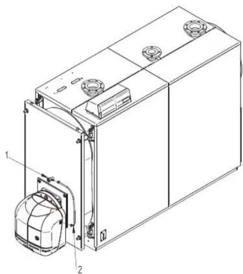
5.8 Connecting the flame inspection window (Fig. 10)
The flame inspection window features a pressure fitting (1) to be connected via a silicone hose or copper pipe to the outlet on the burner (2). This operation allows the air blown by the fan to cool the glass and prevent it from turning black. Failure to connect the hose or pipe to the window may cause the glass to break. For Ferroli boilers, configurations other than those indicated above are also possible, as each combination has been developed in our facilities through specific laboratory tests.
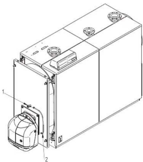
fig.10
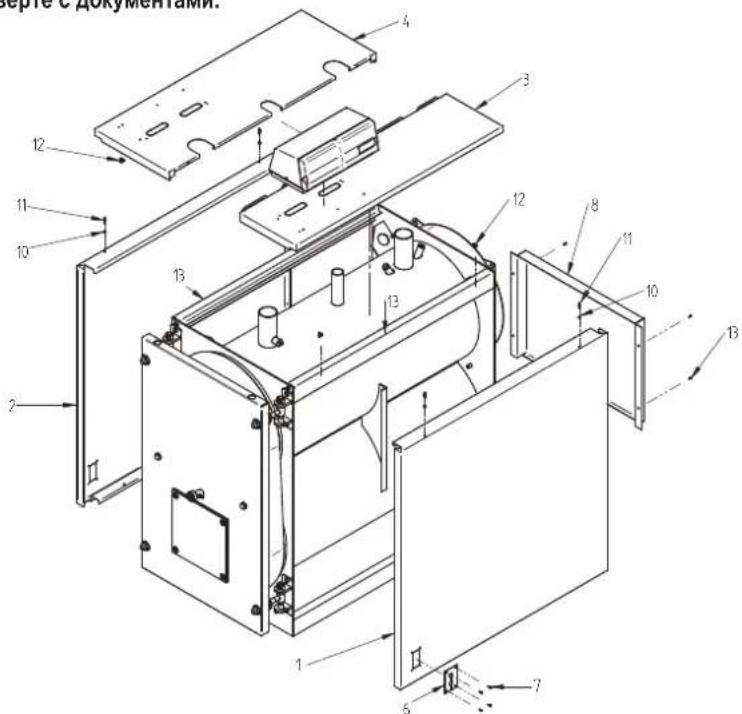
5.9 Assembling the panels, models 92-190
Assembly sequence (Fig. 11)
a) Position the right and left side panels (pos. 1-2) hooking them to the support (pos. 13). To know which of the two sides is the right or the left, refer to the hole for the cable gland plate (pos. 6), which must be facing the front of the boiler.
b) Fasten the control panel to the top panel (pos. 3)
c) Rest the top right panel (pos. 3), complete with the control panel, to the side panel (pos. 1) complete with springs, closing pins and nuts (pos. 10-11-12).
d) Insert the bulbs of the instruments into the sheaths as shown in Fig. 20 and make the electrical connection between the control panel and the power line, burner and any pumps etc. The probes should be inserted fully into the corresponding sockets, to improve contact. Then secure the capillary tubes with the springs. Close the cover on the electrical panel, pass the burner plug through the side plate (pos. 6) and secure the cable with the cable gland supplied. Fasten the plate (pos. 6) with the screws (pos. 7).
e) Fit the panel left top (pos. 4) to the left side panel (pos. 2) complete with springs, closing pins and nuts (pos. 10-11-12).
f) Fit the rear panel (pos. 8) to the boiler using the screws (pos. 13).
g) Fasten the rating label to the boiler, see Chap. 1, after having cleaned and degreased the part in question using a suitable solvent, and apply it so as to ensure perfect adhesion. Do not remove the rating label, as it will lose its adhesiveness.
The rating label is included in the document envelope.

fig. 11
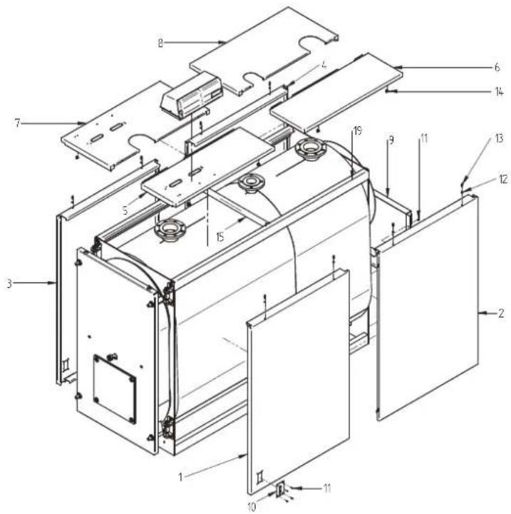
5.10 Assembling the panels, models 240-2360
Assembly sequence (Fig. 12)
a) Position the side panels (pos. 1-2 and 3-4) hooking them to the supports (pos. 19).
b) Position the top right panel (pos. 5-6) and then the left panel (7-8) hooking them to the supports on the boiler (pos. 19) and to the crossbeam (pos. 15).
c) Fasten the control panel to the top right panel (pos. 5).
d) Rest the top panel (pos. 5), complete with the control panel, to the side panel (pos. 1) complete with springs, closing pins and nuts (pos. 12-13-14).
e) Insert the bulbs of the instruments into the sheats as shown in Fig. 19 and make the electrical connection between the control panel and the power line, burner and any pumps etc. The probes should be inserted fully into the corresponding sockets, to improve contact. Then secure the capillary tubes with the springs. Close the cover on the electrical panel, pass the burner plug through the side plate (pos. 10) and secure the cable with the cable gland supplied. Fasten the plate (pos. 10) with the screws (pos. 11).
f) Fit the support (pos. 15).
g) Fit the top panels (pos. 5-6-7-8) hooking them to the side panels (pos. 1-2-3-4) complete with springs, closing pins and nuts (12-13-14).
h) Fasten the rating label to the boiler, see Chap. 1, after having cleaned and degreased the part in question using a suitable solvent, and apply it so as to ensure perfect adhesion. Do not remove the rating label, as it will lose its adhesiveness.
The rating label is included in the document envelope.
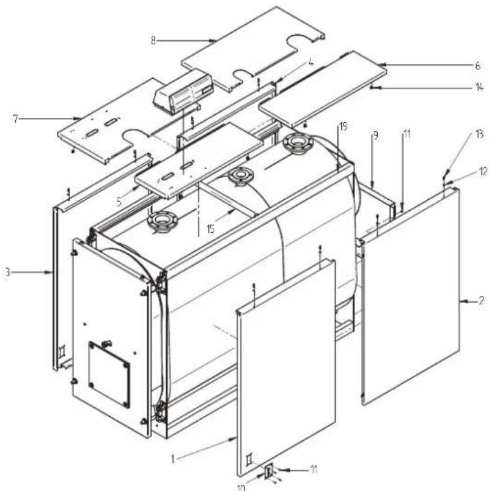
fig. 12
6.COMMISSIONING
6.1 Preliminary checks
Once the hydraulic, electrical and fuel connections to the boiler have been made, the following must be verified before starting the boiler:
- The expansion vessel and safety valve are properly connected and cannot be blocked in any way.
The bulbs for the control and minimum safety thermostats and thermometer have been secured in the corresponding sheaths. - The turbulators have been positioned in all the fire tubes.
- The system is filled with water and completely vented of air.
- The pump or pumps are operating correctly.
The hydraulic, electrical, safety device, and fuel connections have been performed in accordance with current local and national legislation.
- The burner has been installed according to the instructions in the manufacturer's manual.
- The mains voltage and frequency are compatible with the burner and the boiler's electrical equipment.
- The system is able to absorb the amount of heat that will be produced.
- The recirculation pump is installed as described in section 5.5.5.
6.2 First ignition
After successfully completing the checks indicated in the previous paragraph, the burner may be ignited for the first time. This must be done by a technician authorized by the manufacturer of the burner. The technician will be fully responsible for the field of calibration within the declared and approved output range of the boiler. After opening the fuel on-off cocks and checking that there are no leaks in the supply line, place all switches in the ON position.
The burner is now ready for first ignition, and for the adjustments that may only be made by the authorized technician.
On first ignition, check that the door, burner flange and connections to the chimney are tight, and that there's a slight negative pressure at the base of the flue. The fuel rate must match the information on the boiler's rating card. Under no circumstances may it exceed the declared maximum rated output value. The temperature of the flue gas must never fall below 160^ .
6.3 Shutting down the boiler
- Set the operating thermostat to the minimum value.
- Turn off the power to the boiler and cut off the fuel supply.
- Let the pumps operate until they are stopped by the minimum thermostat.
- Disconnect the power to the electrical panel.
7. MAINTENANCE
7.1 General instructions
Periodic maintenance is essential for the safety, efficiency, and long life of the appliance.
All operations must be carried out by qualified personnel. Before performing any cleaning or maintenance operations, the fuel supply must be cut off after first shutting off the power.
For proper boiler operation and maximum efficiency, the combustion chamber, fire tubes and smokebox must be cleaned regularly.
7.2 Routine maintenance
Maintenance must be scheduled based on the fuel used, number of ignitions, system characteristics, etc. Maintenance intervals can therefore not be determined in advance.
As a reference, we recommend the following cleaning intervals, depending on the fuel:
- Gas boilers: Once a year
- Gas oil boilers: Twice a year
In any case, local maintenance standards must be observed.
During routine maintenance, remove the turbulators and then brush the tube bundle and furnace. Remove the deposits accumulated in the smokebox through the open inspection doors. For more thorough cleaning, remove the rear smokebox. If worn, replace the flue gas seal. Check that the condensate drain is not blocked. Make sure the control and measurement devices on the boiler are working correctly.
On this occasion, record the amount of top-off water used. After analyzing the water, perform a preventive descaling.
After repeated fills, the calcium and magnesium salts dissolved in the water will produce deposits in the boiler, cause the metal plates to overheat, and may cause damage that is not attributable to materials or workmanship, and is therefore not covered by the warranty. After performing cleaning and maintenance operations and the next ignition, check the tightness of the door and smokebox. In the event of combustion leaks, replace the corresponding gasket.
The operations performed must be recorded in the system logbook.
7.3 Special maintenance
Special maintenance must be carried out at the end of the season or for extended shutdowns.
All of the operations described in the previous section must be performed, in addition to the following:
- Check the condition of the turbulators for wear.
After cleaning the flue gas circuit, wipe with a rag dipped in a diluted caustic soda solution. After letting it dry, wipe all surfaces with a rag dipped in oil.
Hygroscopic substances (quicklime, silica gel in small containers) should be placed inside the furnace, which must then be closed hermeti-cally so air cannot enter.
- Do not empty the system or boiler.
- Protect the screws, nuts and pins on the door with graphite grease.
The operations performed must be recorded in the maintenance logbook.
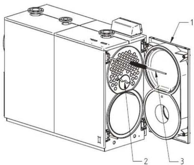
7.4 Cleaning the boiler
To clean the boiler, proceed as follows:
- The boiler comes with a brush for cleaning the fire tubes.
- Open the front door (1) and remove the turbulators (2).
Clean the inside surfaces of the combustion chamber and the flue gas path using a brush (3) or other suitable implement.
-
Remove the deposits accumulated in the smokebox through the open cleaning door (4). For more thorough cleaning, remove the smokebox (5) and replace the gasket before reassembling.
-
Check periodically that the condensate drain (6) is not blocked.
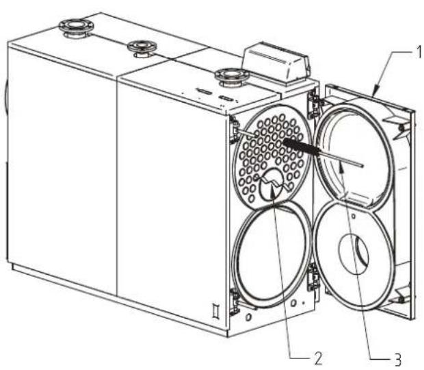
fig. 13
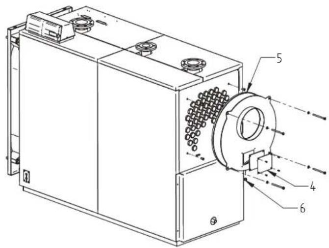
fig. 14
7.5 Checking boiler operation
Before starting the boiler and running the functional tests, check that:
- The turbulators are inside the exchanger tubes.
- The cocks on the water circuit and fuel line are open.
- There is fuel available.
- The expansion vessel is suitably filled.
- The pressure of the water circuit, when cold, is over 1 bar and under the maximum limit for the boiler.
- The water circuits have been vented.
The electrical connections to the mains power and components (burner, pump, control panel, thermostats, etc.) have been completed.
- The phase-neutral connection must be strictly observed, and grounding is mandatory.
After completing the steps described above, the following operations are necessary to start the boiler:
- If the system is equipped with a temperature controller or timer-thermostat, check that they are on.
- Set the room timer-thermostat(s) or temperature controller to the desired temperature.
- Place the main system switch in the "on" position
- Set the boiler thermostat located on the control panel.
- Place the main switch on the control panel in the "on" position and check that the green indicator light comes on.
The boiler will run the ignition phase, and will remain on until the set temperatures have been reached. If problems occur during ignition or operation, the boiler will "LOCKOUT," as signaled by the red light on the burner and the red indicator on the control panel. After a "LOCKOUT," wait about 30 seconds before resetting the ignition conditions. To reset the ignition conditions, press the burner "button/light" and wait for the flame to ignite. If this operation fails, it can be repeated a maximum of 2 or 3 times. Then check:
- The instructions manual for the burner.
- The section "CHECKING BOILER OPERATION."
- The electrical connections shown on the diagram next to the control panel.
Once the boiler has started, check that it stops and starts again:
- Adjust the setting on the boiler thermostat.
- Operate the main switch on the control panel.
- Set the room thermostat, timer, or temperature controller.
- Check that the pumps are not blocked and rotate correctly.
- Check that the boiler shuts down completely by operating the main system switch.
If all conditions are correct, restart the appliance, check the combustion (flue gas analysis), fuel rate, and tightness of the gaskets on the door and smokebox.
7.6 Checking burner operation
- Check the instructions manual for the burner.
- Follow all local regulations and standards with regard to burner maintenance.
7.7 Troubleshooting
The following is a list of the main faults and problems that may occur during boiler operation, specifying possible causes and solutions.
| FAULT | |||
| THE BOILER IS EASILY SOILED | |||
| CAUSE: Burner poorly | adjusted SOLUTION: Check the burner adjustlment (flue gas analysis) | ||
| Flue blocked Clean the flue gas path and the flue | |||
| Burner air intake path dirty Clean the burner air intake | |||
| THE BOILER DOES NOT REACH THE SET TEMPERATURE | |||
| CAUSE: Boiler body d | ty SOLUTION: Clean the flue gas path adjustments | ||
| Boiler/burner combination Check the data and adjustment | |||
| Burner flow-rate insufficient Check the burner | |||
| Control thermostat Check correct operation | |||
| Check the set temperature | |||
| BOILER THERMAL SAFETY SHUTDOWN WITH INDICATOR LIGHT ON THE CONTROL PANEL | |||
| CAUSE: Control therm | ostat SOLUTION: Check correct operation | ||
| Check the set temperature | |||
| Check the electrical wiring | |||
| Check the probe bulbs | |||
| Lack of water Check the circuit pressure | |||
| Air present | Check the vent valve | ||
| THE BOILER REACHES THE SET TEMPERATURE, BUT THE CENTRAL HEATING SYSTEM IS COLD | |||
| CAUSE: Air present in | the system SOLUTION: Vent the system | ||
| Pump fault | Reset the pump | ||
| Minimum thermostat (if featured) | Check the set temperature | ||
| ODOR OF UNBURNED SUBSTANCES | |||
| CAUSE: Flue gas leak | ng into the environment SOLUTION: Check that the boiler body is clean | ||
| Check that the flue is clean | |||
| Check the tightness of the boiler and flue | |||
| FREQUENT ACTIVATION OF THE SAFETY VALVE | |||
| CAUSE: System circuit | pressure SOLUTION: Check the fill pressure | ||
| Check the system circuit | |||
| Check the calibration | |||
| Check the set temperature | |||
| System expansion vessel | Check | ||
- PRESENTATION 45
- MISES EN GARDE GENÉRALES 45
- CERTIFICATION 45
- CARACTERISTIQUES TECHNIQUES, DE FABRICATION ET MESURES 45
- Plaquette technique (2)
5.5 Raccordements hydrauliques
DURETE TOTALE ppm 10
ALCALINITE mg/1 CaCO3 750
PH8÷9
SILICE ppm 100
CHLORURES ppm 3500
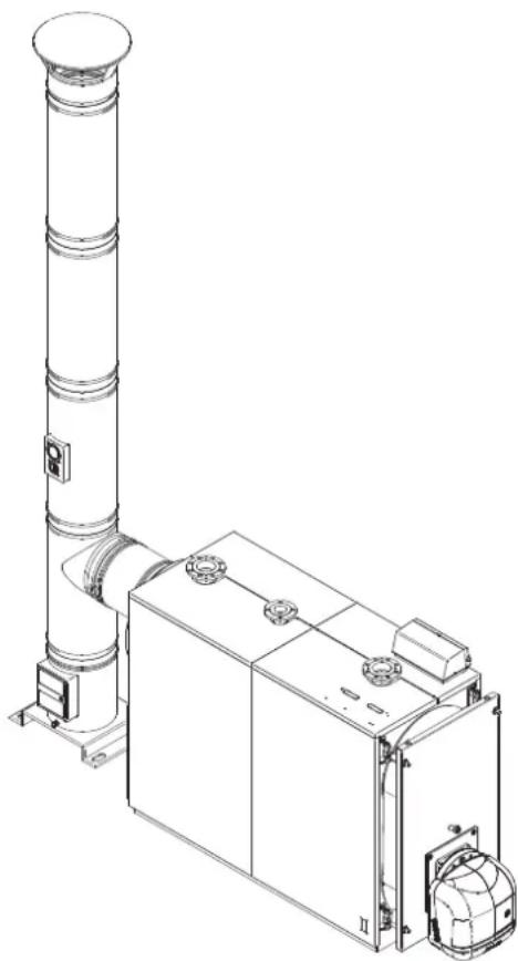
fig. 6
03 = PpOu3BODCTBeHHaH HeJeIa
AC = JINHnC6opKn
0001 = PporpeccnBhoe Yncno
- PPEINCSIOBNE 60
- OBUUNE PEKOMEHDAUIN 60
- CEPTNΦUKALJIA 60
- TEXHnueCKNE INIPOIN3BOIDCTBEHHbIE XAPAKTEPNUCTIKN, PA3MEPbl 60
4.1 Oncanhe kotnoarperata 60
4.2 PnHun paobToB 61
4.3 Texnueckne nokaatei -pa3meby -npabnuueckne coeHHH 62
4.4 63
- MOHTAX 63
5.1 Ynakovka 63
5.2 Iorpy3ka/pa3rpy3ka 63
5.3 TomeueHne KoteIbHO (pnc. 5) 64
5.4 YdaneHne npOyKToB cropania (pnc.6) 65
5.5 Tnpabnueckne npokkouehna 65
5.5.1 Ptatbna Bda 65
5.5.2 Patapy6kn noaHn/Bo3Bpata cncTeMbI OTOpJIeHnA 65
5.5.3 CnCTema HapolneHry/peHaxa 65
5.5.4 PoiKJIIOHHe paacuPteIbHoro 6aka n npdoxpanTeIbHoro Klanana h
5.5.5 PeunpkyIauHnHbH hacoc (pnc. 7) 66
5.6 OtkpbTne npereynipovka nepednei dervn 66
5.7 MoHTaxK ropeNk (pnc. 9) 67
5.8 YctaHOBka rna3ka KOHTpOJI pIameHn (pnc. 10) 68
5.9 MoNTaXn paHenei o6uWKn, moe nn 92+190 68
5.10 MoNTax naHenei o6uBKn, moeinn 240+2360 69
6.BBOB B 3KcIpyATAUIO 70
6.1 PpeBapntelbHbe npoeepK 70
6.2 IepbI 3aynck 70
6.3 OctaHObKa kOTna 70
- OBCJNYKUBAHNE 70
7.1 06uie yka3aHnra 70
7.2 Tekyuuee obcykubane 70
7.3 CneuialbHoe o6cnyKmbaHne 71
7.4 71
7.5 IpoBepka pa6oToocno6HocTn KOTna 71
7.6 DnaHocTnka paobToI ropeKu 72
7.7 YcTpaHHe HeIcnpabNocte 72
1. INPEДИСЛВОВЕ
Ybaxaembl nokynatelb,6narodapm Bac 3a nokynky kotna PREXTHERM RSW N. 3To pykoBDCTBO cneuaNBHO noqroTOBHeO dIra TOrO, yTo6bl O3hakOMtB Bac C IHΦopMauné, Mepamn npedoctopoKHOCTN pekomHdaunm NO MOHTAXy, npabInbHOJ Kcnpnyataumn I TexHneCKOMy o6clyKBAHIO KO7Na.IoxaynctA, IpOHTte erO BRHMATEbHO IN COxpaHNTe DnI NCNoB3OBAHn B DaNbHeWEM. Mbl COBETyEM BAM BHMATeBHO O3hakOMtBCr C CODepXaHMe DMHORO pykoBDCTBA, YTo6bl NcNOB3OBATB 3To BbICOKOaHECTBeHHOE HdENe MAKCImalbHO eFpKeTbHBO.HecobIoJeHne pekomHdaunm IN Yka3AHn, CODepXaUnxCB B DAHNOM pykoBDCTBE, OCBO60JaET N3ROTOBtEner OT IIO60I OTBETCTBeHHOCn I anHyIuPYet rapaHTnIO.
2. OBUNI PEKOMEHDAUIN
3To pyKOBODCTBO RnEeTcHHeOTbEMMeo YactbIO N3dennI INpeOCTabNReT BaxHbIE peKOMeHaun No MOHTaKy, yXOy I TeHXueckomy
-Данhoeи3deneHnDENYCKaETcKИСОнь3OBAHnIONCKHOnTeJIbHO NO pRyMOMy Ha3HaHeHnIO.
JaHHeu 3eHnne npedHa3NaheHo dIHarpeBa BoBb Do TempeaTpbl Hxke ToKn KIneHn I DoJXHO 6bITb NOKJIHOeHO K CNTeMe cHTpaJIbHOrO OTOnJIeHn N/INN CNCTeMe 6bITOBORO RopyeBO BDOCHA6KeHn, B COOTBeTCTBUN Cero XapaKTepNCtHKAMN, OcObeHHoCTMaN N TEPNOB MOUHOCTbIO.
- PpeI npOBeHnEM MOHTaXbIX pa6OT y6eHntecb B TOM. YTO KOTeH He 6bl NOBpeXdE H BO BPEM nORPV3Kn/pa3rPV3Kn I TPAHCNOPTNDOBKN
-KoTeIdoJXKeH6bItbYCTaHOBJIeHHaHEROpIOHeM OCHOBaHHN.
KOTEN JONXEN 6bITb yCTaHOBnH Ha pacctOHRn 6oonee 100 MM OT IIO6oro rOIOHeR MaTePnana HnEero KOMNOHEHTA.
- YCTAHOBKA KOTJNA DOJXHA IPOUN3BOOINTCBKBAINDNIUPOBAHHBIM NEPCOHAIOM IN B COOTBETCTBNN C DeICTBYIOUMN HOPMAMN.
- Peped npoBedeHem IO6bIX pa6OT NO UcCTke IIN O6CNyKBAHN KOTJa. OTKNIOHTe ETO CTn NtAHNA.
IPOIN3BOIDNTIEL He Hecet HnKaKoN OTBcTBeHHocTH 3a yuep6, npHnHeHbI IIOJAM N/IN BeuaM n3-3a Oun6ok npn ycTaHOBKe, HanaKe, o6cnyKBaHmN HnepaBnblHoN 3kCnpyatau.
- KOTEN COOTBETCTBVIOUe OOBYDOBAHNE DOJXHBI 6bITb BBeDEHb I EKCNVATAHUO YONHOMOHHBM INEPCOHANOM.
-BoBDEMBA BONA B3KcPnVATAUMH Heo6XoMIMO VbeJIbTcB INaBnHOCrN daobTH BCex YCTOONCTB DEVNPDBAHM N KOHTDQN.
B cnlyae nnntelbHoro nepnoa npocToor o6opyobanHnI erO 3anycka Heo6xmo npBneHne KbaHmDnnpoBaHoro nepcoHana.
Hopmbi
MOnTaXobOpDobAHnDoJKeH BbInonHbTcBpNcoBIOeHN DeIeCTByOuNX MeCTbIX HOPm NO BbIBopy N NOITROBKe IIOUaKn NOD yctahOBky KOTn, no ObecneHeHHo Heo6xOdBmBix ycNOBn BeHTnJIaUN, No NOdepKAnHIO WTyuePOB, DbIMOBn Tpy6bl N TOINHBbIX Tpy60npoBOOB INeAalbHom CoCToHNN, No 6eONaCHOCTn 3IEKtpuecknx CNTem, a TAKKE BCEx Dpynx DeIeCTByOuNX npabIN 6eONaCHOCTn Oxpahbl Tpyda.
TapaHTmHbIe 6o3aTeNbctBa
IpaHTnHbte 63aTeBCTBa RnIOCTeNtBHeIMTOJbKO npu yCNOBm co6IOeHnBCex HOpM n peKOMHeaun, cOepKaUxCR B daHOM pykoBDCTBE. Hco6IIOHeH Hopm n PnBeDeHHbIX peKOMHeau nnlaaetnpaHa rapaHTnHynoNDepkky. IpaHTn He pacpncptpanreTc Ha cnuyan noBpeKdEHN KOTNA B pe3yblTaTe BO3eJeCTBnK MCLNOTHO KOHdHcTa npOdyKTOB CropaHn Nn OTNOXeHn HaKNn B pe3yblTaTe NCNoJIb3OBAHn JKeCTKoN INN arpeccNBHO Bobl, NOckONbky DaHbIe NobpeKdEHN RBLIOCTcJeCDTBm EKCIpytaUN O6OpyDobAHN.
3. CEPTNΦIKALIN

Mapkpobka CE noTBepeKaet, yTo 3dene CoOTBcTBye OCHOBHbIM Tpe6oBaHnM npaBn GAr n Dpynx DeiCTByOuixm Dmpektnb.
Deknapaun o cooTBeCTBm MOKet 6bIt npedocTabHeHa npOn3BounteIeM.
INDHTNΦUKAUNOHHBIEKoDbI N3DEJIN
- NaKeTeY DOKyMeHToB (1)
KOTOpBIMeETcH a nepeDHeN DBeepn COeepXHT
TEXHINUECKOE PYKOBODCTBO
TAPAHINHBI CEPTNOKAT
HAKJEIKCOSHTPXXKOJAMN
WIIINbDnK
CBNDETEJIbCTBOIPIEMKIN
5.7 MoHTax ropeKn (Pnc. 9)
MoHTaK ropeKn Ha DBeB kOTJa DOJKeH oEeChuBaT b 6cOJIIOTHyO rAOnIOITHOCTb IIN pOdyKTOB cropAnH. Tocne MoTAtka ropeKn Ha KOTen, 3aOp MExny rHezdom ropeKn n OReHyNOpHbIM MaTePnAmoH Ha DBePn DOJKeH 6bTy 3aONHeH Cnoem KepamUeCKoro Uhpya (A), NoCTabnEmoC KOtIOM. 3To npedotBpauaet DBeB ot neperpeBa n, KaK cJeDCTBne, OT OCTaTOHH DeOpMaun. POnkIoUeHnRAODaH ToPnIBa K ropeKe DoJHKbI pacononaratcb Taq, YTObI NOBONr BNOHoe ONKpbItNe DBePn KOtJa C yctAHOBHeHOr ROpeKoN.
| Мо dyeл L мин. | (MM) L м akс. | (MM) |
| 70-152 230 | 300 | |
| 190-240 250 | 320 | |
| 320-401 290 | 360 | |
| 500-600 320 | 390 | |
| 720-820 320 | 390 | |
| 940-1060 340 | 410 | |
| 1250-1480 340 | 470 | |
| 1890-2360 350 | 480 |
pnc.9
5.8 YcTaHOBbKa rJa3Ka KOHTpOJI pJaMeHn (Pnc. 10)
Глбдгьгьгьгьгьгьгьгьгьгьгьg (1), KOTOPOEДОЛЖHO NOДКЛHQUATbC RINKHOBOH INI MEHNO Tpy6kON K BbIXOy Ha ropeJIke (2).Takay KOHCTpyKUIN NO3BOJNET BO3dxy, NOCTyNAIOeMy OT BeHTNIArTOPA ropeIKO OxJAAqDaT bCTEKN I pEDoTBApaAeT erO OT 3aOKnHBaHry. HeNCnPabHocTh npICoeHNHeHry Tpy6Kn K Tla3ky MoKeT Bb3BaT NOlOMKy Tla3ka.
HarpeBaTeIbHbIe yCTaHOBKn FerroI MOrY IMeTb KOHpypaHIO,OTNIuHyIO TnpBedeHHbIX BbIe, B CBy3N C TEM, YTO BCE DOnONHeHn6 bInn pa3pa6OtaHbB HauWe KOMNaHm N npoJn Na6opatOpHbE nCbItHaH.
pnc.10
5.9 YcTaHOBKa nHaHeIeN o6uINBKN, moDen 92-190
IocneobatebHoctbMOHTaKa(pnc.11)
a) YctahOBtE 60KObIe npabBle n neBbIe naHEn (no3.1-2) 3akpenNB uX Ha epkxtene (no3.13).ДЯ onpeDeneHn KaKaJn 3 cTOpOH npabBa IINJIIEBAObATNE BHNMaHHe Ha OTBepCTne B pIacTInHe dIy npoBOKn Ka6eJeN (no3.6), OHa DoJnxHa 6blb nobepHyTa B npeDHO CTOpOHy KOTJa.
6) 3aKpeNITe naHb ynpabLeHnHa bepxHIO naHb (no3.3).
B) YcTaHOBtE BepXHIO npAByIO naHeIb (no3. 6) C naHeIbIO ynpaBJIeHna H6OKoByIO naHeIb (no3. 1) BMeCTe C npyKHO, nepeKNaIHAMn I raikamn (no3. 10-11-12).
r) Bctabte B yexnb kon6bI dAchkoB, Ka n oka3aHO ha pnc. 20 n npo3BeHne 3JeKTPueeckoe noKnIOueHne naHEn ynpabnHn Knnn HnTaHn, ropeKe, hacocy n T.D. PekomeHnyetc BCTaBntb daTNN do ynpoa B COOTBETCTBYUeNE KONoDzbl, oecneHNB X KONTAKT. 3aTEM 3akpennte npyknkamn. 3akpoTe KpbuKy 3JeKTooHTa, npoeHne Bnky ropeKNe Upe3 60KOByo nnactHy (no3. 6) n 3a6NOKpyTe KaebI npn nomou nocTabneHHoro 6bokapatopa. 3akpennte nnaCTHy (no3. 6) BNHTAMn (no3.7).
B) YcTaHOBtE BepxHIO neByIO nAneIb (no3. B) B BoKOByIO neByIO nAneIb (no3. 2) BMeCTe C npyKINOH, nepeKnAnHAMm I raiKAMn (no3. 10-11-12).
r) YcTaHOBtE 3aHIOI NaHeJIb (no3.8) Ha KOTeI I 3aKpeINTe BnHTAMN (no3.13).
I) IIOHTHO npnKpEnITe Ta6nnuCy c DaHHbIMN KOITla (CM. rII. 1.4), OOHCTNB N o6e3xkpNB pactBOpNTeEM 30Hy yctaHOBKn. He CHIMaIte Ta6nnuKy, TAK KAK OHa 6ydt npnKneNBatbcra.
Ta6nUka HaxoHTcB KOHBepeC DOKyMeHTaM.
pnc.11
5.10 MoTaxnHaHeJn MoJ.240-2360
TocneobateIbHoctMoHTaKa(pnc.12)
a) YCTAHOBNTe 6OKOBbIe NaHEn (no3.1-2 n 3-4), 3aKpeINB INx HA DePkaTeJx (no3.19).
6) YctaHOBtE 6OKOBbIe BepxHHe naHEn (no3.5-6), a 3aTeM n IeBle (7-8), 3aKpeNMB uX Ha IepXaTeTnKoTna (no3.19) u HA nonpeHHe (no3.15).
B) 3aKpEnIte naHEn ly npabJeHnHa HbepxHIO npabyo naHEn (no3.5).
r) YctaHOBtE BepxHIO HnHeIb (no3.6) Bmecte C nHaHbIy UnpaBHeHna60KOBHy nHaHEnb (no3.1) Bmecte C npyKnHO, nepeKlaHAMn I raikamn (no3. 12-13-14).
d) Bctabte B ueXbI KOJIbI HnCTpyMeHToB, KaN oKo3aHO Ha pnc. 19 n npOn3BeIe 3NeKtpueeCKoe NOKnIOueHne naHEn ynpabHeHn K NINHN PNTAHNA, RopeKe, Hacocy n T.D. PeKomeHdyETc BCTaBnT b DaTHKN Do yNopa B COOTBETCTByOuine KOLOUBI, O6ecNEuH N KONTAKT. 3aTeM 3akpenITE npJxHHkAMn. 3AkpoTe KpbIky 3NeKtpouHTa, npOBeIte BnIKy ropENKu yepe 6okobuyn pAnactHy (no3. 10) n 3a6NoKpyte Ka6en bpn nomOu nocTabneHHoro 6nOKupatopA. 3akpenite nnaCTHy (no3. 10) BNHTAMn (no3. 11).
e) YCTaHOBInTe DepeXaTeInb (no3.15).
K) YctaHOBnTe BepxHHe NaHeN (no3. 5-6) 3akpeINb INx Ha 6okOBbIX NaHeIax (no3. 1) BmecTe C npyKHaMn, nepeKlaDnHaMn I raKaAMn (no3. 12-13-14).
3)ПnotHO npKpeHnTe Ta6nHy c DAHHbIMN KOtna (CM. rI. 1.4), OCHCTNB n oBe3xKnPbB pactBOpHTeM 3OHy yCTaHOBKn. He CHImaiTe Ta6nHy, TAK KAK OHa 6yDet npKneNBaTbcra.
TaBnUka HaxoHTcB KOHBePeTc DOKyMeHTaM.
pnc.12
6.BBOB B3KCNJYATAUIO
6.1 PpeBapnteIbHbe npoBepkn
Iocne BbInonHeHn rindpaBnuecknx, 3neKtpnuecknx n ToTnINBbIX nOKnIOeHn K yctaHOBe nepe npBBm 3anycOM npOBepbTe, YTO:
- pacuipntbHbI 6ak n npdoxpaHtBbI KJanaan npaBnBHO NOKJIIOUeHb I He MOryT bblpekpbl;
- DaTUNK peryIINPOBOUHbIX IN npEOxPaaHNTbHbIX TepMOCTaOIB IN TepMOMETpa HAnExKHO 3aΦIKCpOBAHbI BHYTpN COOTBETCTBYOUXIN FInb3;
- BO BCEx ΣbIMOrapHbIX Tpy6bx yctaHOBnEhbl Typ6yIIN3aTOpbl;
- CNTema 3aONHeHa BOIOI IN BO3DyX NOHOCbIO CTpaBNeH;
- Hacoc nnn Hacocb pa60tao npabnblho;
IINpABInueckne n 3JIeKTPnueckne CoeHHeHna, yCTPOINCTBa 6e3OpaCHOCTN NdbIMOXoB I NOKJIIOUeHbIB COOTBETCTBN C DeIcTBYIOUMN HauioHOJIbHbIMN MecTHbIMN HOpMaM;
-ROpeIka yCTaHOBJIeHa B COOTBeTCTBm C INHCTpyKUJIMM, IN3IOJKeHHbIMN B TEXHnueeCKOM pyKOBOJcTBe IN3rOBoNTeJIa; - HaprykeHne uacToTa 3JekTpuecko ceTn HaxOJaTc B COOTBeTCTBm C TexHueckMn XapaKTePncTnKaMn TopeKn n 3JekTpoo6bOpyDobAHn KOTnla;
- CNTema B COCTOHN INPINHbT TENIO, KOtOpoe 6yET INPON3BedeHO TENTIOReHepaTopoM
- peunpkyIJIauIOHHbI Hacoc yCTaHOBnEe TAK, KaK OINcAno B pa3d. 5.5.5.
6.2 NepBbI 3anyck
Pocne ycneHoro BbINONHeHnBCEXPOBeK, ONmcaHNbX BnpdeIyUeMpaZdene, MoxHO BbINONHTb npbb3aynckropeK. 3Ta npoeDpya DOJNkHa BbINONHbCRA CNEuAnlntom, AKKpeiITOBaHHbIM N3ROTOBtEnem ropeK. 3TOT CNEuaInCT Hecet NnHyO OTBeTCTBENoCTb 3a KaN6pOBky HnAaKy ropEKN Bnpedax 3aRbEHHoro Y TBPekDeHHoro DnAna30Ha MOuHocTN. Pocne OTKpbTyN 3anpaHouix TonNHBHX 3aDbNke K npOBepKn OTCYCTBnY TeueK B Lnnnno TaonnBa, nepeBedeTe BCE BbIKNoHateN B noLoXeHne BKJI. TenepbropeKra rotoba K nepbOMy 3anycku HaCTpoKe, KOtbpie DoJnKhblipOn3BOHTbcy yNOHMOueHHbIM cneuaInCTom.
Pn nepbom 3anyce y6eintecb, TTO nepeHnra Dberpa, fnaheu ropeKn n noKIOUeHHN K dbMOB Tpy6 RaIIOHTbIMn, a HxOe BdbMOXo npncyTcByet He6oBloWoe OtpuataeBHOe daBHeHne (Tara). PpOn3BOInTeBHOCTb TOnINBONODaH DoNKHcoOTBeCTBOBaTbTexHueckm XapakTePNCtukam KOtnn Hn B Koem Cnyae He DoJNKHa pReBbIaTaMakCmAlbHOrO 3NaueHHa 3aRbIeHHo paChETHO MoUHocTN. Temepatypa yoxdunx ra0B HkOrDa He DoJNKHa 6bItb Hnke 160°C.
6.3 OctaHOBka KOTna
- YctahOBInTe MmHmAbJIbHOe 3NaueHne pa6Ouye TempeaTpybl.
-ObecToBte ropeKny npeKpoTe noaCy ToJIInBa. - Octabte HacocbI B pa6ote Do Tex nop, Noka INH He OTKIOHT TepMOCTaT.
-06eToBte 3nEeKtpouuNT.
7. OBCJNYKUBAHNE
7.1 06uyeyka3aHnna
PepnoDnueckoe 06cnykubAHne Heo6xOIMO dIg o6ecneHn8 6e3onacHOCTn, 3ΦΦeKTHBHOCTn I dIITeJIbHOrO cPoka 3KcIIyatauMn 6obopydOBaHn.
Bce onepaunn DOnKbHb BblonHbTcB KBaanHmnpoBaHHm nepcoHaON. Bce onepaunn no uCtke n 06clyXBAHnO KOtnna doJxHBn npou3BOuNTbc npn 3akpytonnoaue tonnba n OTknUohEHOM 3neKTPOcha6xHnn.
IpaBnboHpaobtIIMAKcImaHbHO 3ΦΦeKTHBHOCTN KOTNa Kamepy CROPAHNA, DbIMORAPHbIE Tpy6bl NdbMOBON KOJIneKTOp HEO6XoDMOPeyJrphOuNCHTb.
7.2 Tekyuueo6cnyKuBaHne
PepnoDnHOCtB uNCTKN He MoKcET 6bITb ONpeJeHa 3apaHe, TAK KAc OHa 3aBNCIT OT TUNA NcNoJIb3yEMOTo TOJIINBa, INHTECNBHOCTN NcNoJIb3OBAHn, XapakTepeNCTNK CNTeMbI N.T.
BIO60m cnyae MHHMaJIbHa nepnOduHocTb Ipa3HbIX TINOB TOINBA COCTaJIeT:
-ra3:OdINpa3BroD;
-Ди3eьHoeToPnINBO:Дba pa3aВ roD.
B IIO6oM cIyue cIeIyET B nepByIO OepeIb PnIepKmbatcBcIeICTBYIOxN MeCTbIX HOpM n CTAnapTOB.
Bo Bpem Tekyuero 06cnykBaHnna, nocne ydaIeHnry Typ6yn3aTOpOB, npOcn7te zetKamn Tpy6hbl nyok n Tonky. OtkpoTe HnCNEKIOHOHbIe IIOChn u ydaIIne Harap n OTIOXeHn, cKONIBWinecB a DbIMOBOM KOnKeTope. IINa Boonee INTEHCNBHO ONCTKN ydaIIne 3aHN dMbOBOK ONKeTOp n, pIn HAInuHn NOBpeJdeHn, 3aMeHnTe yNtOTHNOU MaHKeTy. Y6eNTecb, YTO CnCTema OTBODa KOHDeHcata He 3a6NoKpObaHa. Y6eNTecb B Tom, yTO yCTpOncTBa N3MepHnN ynpabJIeHnRApaOtaeT npabNlHo.
3aepbte pacxod noDnHTOHy BObl, n, noCne npOBedeHnaHn3a BObl, npOBeNTpe npOtnakTtueckyO uChkTy OT HAKIN.
Pn NOBTOPOUUXCn POINNTKAX pactbOpEHHbIe B BOE cONN KANbUaN N MaTHN Bbl3bBaIOT OTIOXeHN HaKNN B KOJIe N nepepeB MetaTNNuecknx NOBExPHoCTe, YTO MOKeT PnBecTe N NOBpeXeHnM, KOtObe HEnb3r OTHeCTu H N K HeNoCTaTKam UcNOJb3OBaHHbIX pni 13ROBHeHn arperata MATEpnaNoB, H N K IpnON3BODCTBeHHOMy 6paKy. COOTBETCTBehHO, TAKne CnyuaH Ne 6byT JABTbcra rapaHTnhbbIMN.
Pocne okohannpaobot no nuchte n ocbnykbanHIO nOBtporHO 3anycka KOTna npOBepe Te raONIOTHOCTb DBepuNn DbIMBOrO KOJIeKTopa, n, B clyae obnapyken yteckn npOdykTOB cropanHn, 3ameHnte COOTBEcTByUOue npOKJaKn.
BbInonHeHHbe onepaun DoJxHbI 6bItb 3aHeceHb I KypHaN 3KcPnyataun yCTaHOBkM.
7.3 CnueuaNbHoe o6cnyXuBaHne
Cneuaalbhoe 06cnykBaHnne npOn3BODITcB KOHc eToNTbHOr c0eHa Hnnped npOOnKmTebHO octaHOKoTNa.
OcyeCTBITE BCE Oepaun, ONncanHbIe B npdeIduyem pa3dene, a TAKKe:
- npoBepbTe TpyuHa3aTOpbHa npEMeT H3HocA;
IPOHCTNTe r30xOdbI n o6pa6oTaIe Ix pactbopom kayctnuecko coDbI; Nocne BblcIxAHnI npOTpITe BCE NOBepxHOCTM MaCnaHOI TpIKNK;
TnRPOCKONHueckne BeueCTBa (Heraaeha HNBeCTb, CNIIKARINB He6oNbX EMKOCTeX) CNEyET NOMECTNTB BHYTpB TOKN, KOTOPA 3ATEM DOnxHa 6blr repMetTuHO 3akpIta, TAK YTo6bl npedotBpaTntb CBO6OHDh IOCTyn BO3dyxa;
-
He CINBaIte CInCTEmy KOTen;
-
06pa6oTaIe BnHTbI, raKN, StnΦtBi DBePcBi rpaHnTOBoi Cma3Ko;BbINONHeHHbIe Oepaun DoJXhbl 6bTb 3aHeceHbI B JxypHaN 3Kcnjlyatauun yCTaHOBKn.
BbInonHeHHbIe onepaunn DoJxHbI 6bITb 3aHeceHb I bKypHaJI 3Knpyataun yCTaHOBkM.
7.4 YnCTKa KOTna
YnCTKa KOITIa npOn3BOoNTcN CNeDyUOuIM O6pa3OM:
-BMECTK KOTJOM NOCTABNRETC CNEUHaJIbHAR IETKa DnYIcTKn DbIMOBbIX Tpy6;
- oTKpOte nepeDnIO DBepy (1) u ydaIaTe Typ6yIm3aTOpbl (2);
IpoHCTnTE BHTpeHHne NOBepxHocTN KamepbICropaHn Ira3oxoDbI,NCnonb3yIeTKy (3) ININ Dpyrooe noDxoJaee dnn 3toN npncnocobene;
Yepe3 OTkpblTbI JIOHOK 6cnyKmbAHn4 (4) ydaNITe OTIOXeHn, HAKONNBWueC8 B DbIMOBOM KOJIIEKTOpe; dIyJyWeOuCTKN ydaNITe KpbIkwky dbIMOBORo KOnNEKTopa (5) n 3aMeHnTe yIpNoTHraUOyIO npoklndy nepeD NOBtropHO c6OpKO;
-пегионческ поверяnte,чTo сntema снIBa KOндсata (6) He 3akynopena.
pnc.13

pnc.14
7.5 IpoBepka pa6oToCnOc6HocTn KOTna
Ipeed 3aynckom npobepko pa6oTOcNO6HOCTn KOTna y6eINTeCB, YTO:
Tpyn3atopbpaacnonarakcBHytpntennooMeHHbix Tpy6
- BeHTnI rIaPbAINueCKO KOHTpya I NcCTEmbl IIOdaUH TOnJIbA OTKpbItbI;
- TONNBO IMeTcB HAIINH; -paCUnpTeIbHbI 6aK DoCTaTOH OHaNOHHeH
XOIOHOe DaBHeHne BnDpaBnuecko CNTMe NpeBbIaet 16ap H He DoCTnraet MAKcMmaJIbHorO pa3peuHOrO daBHeHnKOTnA;
- BO3dyx CtpaBnEn H3 rnpabnnuecko cnCTembl;
3aKOHHeI;
- coeHHeHne MeKdy qa3oH HeItpaIbIO npOBepeHO, a yCTaHOBKa 3a3EmJeHa.
Pocne OKOHuaHnO nncAHbIX Oepaun dna 3anycka KOTna Heo6xOIMMo BblonHnTb CneJeUOpune DeiCTBnA:
- ecn ci nctema oobopyoBaHa TepmoperyIaTOM INxPOHOtePmoCTaTOM, y6eNTeCb, yTO OH HAXOITcB NIOJIOKeHIN «BKIOUeHO»;
yCTaHOBtE KOMHaTHbI XPOHOtePmOcTaT NJIIN TepMOperyJrTOp Ha KeJaemoe 3HaueHne TEMpePaTypbl - NepeBcDNTe TJIABHbI BbIKHNoaTeJIb CnCTEmbl B NOIOXKeHne (KbHIoYEOHO)
-OTperpyntyTe TepmoCTaKOTna,paCnONOKeHHbHa naHEn ynpaBneHnra;
Koten nepeienet B pexim 3anycka n 6ydet octabatbca B hem do doctnkehny yctahOBneHHoem Tmnpaypbl. Ecn BO Bpem 3anycka n npapobtbl Kotna Bo3nKHyT kakne-niboo HeucnpabHoctn, arperat 6ydet OCTAHOBNEH', a ha ropelke n naheyn ynpableney 3axkrytcn Kpachble nndkaTopb. B cnyae 6noknpBkn Kotna cneJyert bixdaT he Menee 30 ckynd neepd nobToPbHm 3anyckom. Ira toro tO6bl BocstaHOHT yCNOBn 3anycka, haxmte KNOpK Y BbIKNoUeTaB/niNOT' Ha ropelke ndoxntecb noRbHe HnnrEHa He 3axfIacb, onepaun MOket 6bIt NobTopeHa Maksym 2-3 paa, nocle yero cneJyET o6paTntcb:
- K INHOpMaCmN, NOCTaBnIeMoB B INHCTpyKuN N3ROTOBtEnE M ropeKN;
- K pa3dny «ДИАГHOCTNKA PABOTbI KOTIIA»;
K CXEme 3eKtpueeCKNX NOkKnOHeHn, NoCTaBnEMoC nYbTOM ynpabNeHn.
Iocne 3anycka kotna, y6eintecb, yTO OH oCTaHabnBaetcra, 3anyctnte erO cHOBA cJeDyUOIm 0bpa3OM:
OTpeynpyte HactpoKy TepmoCTa KOTn; -peeknoHTe BbIKNoateNkOTna Ha naHeiyn npabneHnA
- HacrpoTe TepMoCTaT TempeaTypbI BO3dyxa B NOMeUeHN, TaMep NIM TepMoperyJrTOp;
- npOBepbTe,TO potOpbl HACOCOB CBO6oHNO BpaauaOTcB INpABuHbOM HnPaBnEHM;
- npoBepbTe cpaabaBAHne nonHO octaHOBKn KOTJa, nCIOB3yra IaHBHy BbIKIOaTeNb.
EcnBce yctpoCTBa cpa6oTn npabInbHo, nepe3anycTne yctahOBky, npoepe Te kaeeCTBO cropana (no aHann3y yxoJxix ra3OB), pacxoad TOnJIbBA nra30IIOHTOCHTB DBepuN NdbIMOBTO KOJIeKTopa.
7.6 Dnarrhoctka pa6oTbI ropeJKN
- O6paTntecb K pykoBOOdCTBy nO 3KcNpIyatauINr opeJIKN;
- pni o6cnykuaHH ropeJIKBbInONHnIe Oepaun corlacho DeiCTByUOM HopMaM.
7.7 Yctpaehne HncnpabHocte
Ipeueheb OCHOBhIx HEnCnpaBHOCTe INH HENONADOK, KOToPbIe MOrTy BO3HNKHyTB B npoucece 3KcnIpyaTuIN KOTNa, C yKa3aHHeM IX BO3MOXhBIX pInuHH mEtOIOB yCTpaHEHn, pNBeHn HnKe.


- INTRODUCTION
- GENERAL WARNINGS
- Standards
- Warranty conditions
- CERTIFICATION
- Description of the appliance
- Operating principle
- Key
- Identification
- INSTALLATION
- Packaging
- Handling
- Boiler room (Fig. 5)
- INSTALLATION IN OLD SYSTEMS OR SYSTEMS TO BE UPGRADED
- Discharge of the products of combustion (Fig. 6)
- Water connections
- Supply water
- Central heating outlet/return pipes
- System fill/drain pipes
- Expansion vessel and safety valve pipes
- Recirculating pump (Fig. 7)
- Opening and adjusting the front door
- Key (Fig. 8)
- Assembling the burner (Fig. 9)
- Connecting the flame inspection window (Fig. 10)
- Assembling the panels, models 92-190
- The rating label is included in the document envelope.
- Assembling the panels, models 240-2360
- 6.COMMISSIONING
- Preliminary checks
- First ignition
- Shutting down the boiler
- MAINTENANCE
- General instructions
- Routine maintenance
- Special maintenance
- Cleaning the boiler
- Checking boiler operation
- Checking burner operation
- Troubleshooting
- Raccordements hydrauliques
- INPEДИСЛВОВЕ
- OBUNI PEKOMEHDAUIN
- Hopmbi
- TapaHTmHbIe 6o3aTeNbctBa
- CEPTNΦIKALIN
- MoHTax ropeKn (Pnc. 9)
- YcTaHOBbKa rJa3Ka KOHTpOJI pJaMeHn (Pnc. 10)
- YcTaHOBKa nHaHeIeN o6uINBKN, moDen 92-190
- MoTaxnHaHeJn MoJ.240-2360
- 6.BBOB B3KCNJYATAUIO
- PpeBapnteIbHbe npoBepkn
- NepBbI 3anyck
- OctaHOBka KOTna
- OBCJNYKUBAHNE
- 06uyeyka3aHnna
- Tekyuueo6cnyKuBaHne
- CnueuaNbHoe o6cnyXuBaHne
- YnCTKa KOTna
- IpoBepka pa6oToCnOc6HocTn KOTna
- Dnarrhoctka pa6oTbI ropeJKN
- Yctpaehne HncnpabHocte
Brand : FERROLI
Model : TP3 LN
Category : Boiler