PREXTHERM RSW 1250N÷6000N - Boiler FERROLI - Free user manual and instructions
Find the device manual for free PREXTHERM RSW 1250N÷6000N FERROLI in PDF.

User questions about PREXTHERM RSW 1250N÷6000N FERROLI
0 question about this device. Answer the ones you know or ask your own.
Ask a new question about this device
Download the instructions for your Boiler in PDF format for free! Find your manual PREXTHERM RSW 1250N÷6000N - FERROLI and take your electronic device back in hand. On this page are published all the documents necessary for the use of your device. PREXTHERM RSW 1250N÷6000N by FERROLI.
USER MANUAL PREXTHERM RSW 1250N÷6000N FERROLI
PREXTHERM RSW 1250N÷6000N
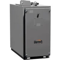
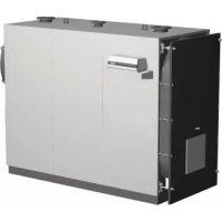
High-efficiency boiler for liquid or gas fuels
natural_image
Exterior view of a gray industrial furnace or reactor unit with mounting flanges and a central vent (no visible text or symbols)1250N÷1890N
natural_image
Industrial cylindrical mechanical device with black housing and mounting flanges (no visible text or symbols)2360N÷6000N
EAC
CE
ES
IT
EN
FR
RU
INSTRUCTIONS FOR USE, INSTALLATION AND ASSEMBLY
INSTRUCTIONS D'UTILISATION, D'INSTALLATION ET DE MONTAGE
text_image
F I B E N O P T1 T3 T2 T5 3 T4 L1
text_image
T1-T3-T2 T5 T4fig. 4 - RSW 2360N÷6000N
4.4 Identificación
natural_image
Technical line drawing of a mechanical enclosure or enclosure frame with internal components and structural supports (no text or symbols)fig. 5
natural_image
Technical line drawing of a mechanical device with a crane lifting a component (no text or symbols)natural_image
Technical line drawing of a vertical cylindrical device mounted on an electrical box (no text or symbols visible)fig. 8
text_image
Technical diagram of an industrial machine with numbered components for identificationfig. 10 fig. 11
text_image
Technical diagram of a mechanical assembly with numbered components for identificationPie (Fig. 10)
text_image
L S A Ø0000fig. 12
text_image
Technical diagram of a mechanical device with labeled components 1 and 2, showing internal components and wiring.fig. 13
text_image
Exploded view diagram of a refrigerator with numbered components for identificationfig. 14
6. PUESTA EN MARCHA
6.1 Controles preliminares
text_image
Technical diagram of a mechanical device with labeled components, showing internal components and assembly steps.fig. 15

text_image
Technical diagram of a mechanical assembly with labeled components, showing a housing and internal components.fig. 16
text_image
F I B E N O P T1 T3 T2 T5 G 3 T4 L1
text_image
T1-T3-T2 T5 T4fig. 4 - RSW 2360N÷6000N
4.4 Identificazione
natural_image
Technical line drawing of a mechanical enclosure or enclosure frame with internal components and structural supports (no text or symbols)fig. 5
natural_image
Technical line drawing of a mechanical device with a crane lifting a cylindrical component (no text or symbols)natural_image
Technical line drawing of a vertical cylindrical device mounted on a base with control panel (no text or symbols)fig. 8
text_image
Technical diagram of an industrial machine with numbered components for identificationfig. 10 fig. 11

text_image
Technical diagram of a mechanical assembly with numbered components for identificationLegenda (Fig. 10)
natural_image
Technical line drawing of a mechanical device with labeled components (no text or symbols present)fig. 13
text_image
Exploded view diagram of a refrigerator internal structure with numbered componentsfig. 14
text_image
Technical diagram of a mechanical device with labeled components, showing internal components and assembly steps.fig. 15
text_image
Technical diagram of a mechanical assembly with labeled components, showing a housing and rotating disk assembly.fig. 16
- INTRODUCTION....29
- GENERAL WARNINGS....29
- CERTIFICATION......29
- TECHNICAL AND CONSTRUCTIONAL CHARACTERISTICS, DIMENSIONS....29
4.1 Description of the appliance 29
4.2 Operating principle....30
4.3 Technical data - Dimensions - Hydraulic connections 31
4.4 Identification....32 - INSTALLATION 33
5.1 Packaging 33
5.2 Handling....33
5.3 Local de instalación (Fig. 7)....33
5.4 Discharge of combustion products (Fig. 8)....34
5.5 Hydraulic connections....34
5.5.1 Supply water 34
5.5.2 System feed/return pipes 35
5.5.3 System fill/drain pipe 35
5.5.4 Pipes, expansion vessel and safety valves.... 35
5.5.5 Recirculation pump 35
5.6 Adjusting the front door....35
5.7 Assembling the burner (Fig. 12)....36
5.8 Connecting the cooling tube to the flame inspection window 37
5.9 Assembling the panels, mod. PREX THERM RSW 1250N÷1890N 37 - COMMISSIONING 38
6.1 Preliminary checks....38
6.2 First ignition 38
6.3 Shutting down the boiler 38 - MAINTENANCE....38
7.1 General instructions....38
7.2 Routine maintenance....38
7.3 Special maintenance 39
7.4 Cleaning the boiler 39
7.5 Checking boiler operation 39
7.6 Checking burner operation 40
7.7 Troubleshooting 40
1. INTRODUCTION
Dear customer:
Thank you for choosing a PREXTHERM RSW N boiler. This manual was written to provide information, warnings and advice on the proper installation, use and maintenance of the boiler.
Please read it carefully and save it for future reference. It is in your own interest to carefully follow and observe the instructions given in this manual, in order to fully enjoy this high-quality product.
Failure to comply with and observe the instructions contained in this manual exonerates the manufacturer from all liability, and invalidates the warranty.
2. GENERAL WARNINGS
- The instructions manual is an integral part of the product, and provides a description of all instructions that must be observed during the installation, use and maintenance phase.
- This appliance must only be used for the purpose for which it was expressly intended.
- This appliance is intended to heat water to below-boiling temperatures at atmospheric pressure, and must be connected to a central heating and/or domestic hot water distribution system, in accordance with its characteristics, performance, and heat output.
- Before installation, check that the boiler has not been damaged during handling and transport.
- The boiler is to be installed on a non-combustible base.
- The boiler is to be installed with a distance of at least 100 mm to any combustible material or component.
- The installation must be performed by duly qualified personnel, in accordance with current standards.
- Before performing any cleaning or maintenance operations, unplug the appliance from the mains power supply.
- THE MANUFACTURER is not liable for any damage to people or things due to errors in installation, adjustment, maintenance, or improper use.
- The boiler and corresponding system must be commissioned by authorized personnel.
- Commissioning is performed in order to verify proper operation of all adjustment and control devices.
- Qualified personnel must be contacted if the appliance is not used for an extended period.
Standards
The installer must observe current local regulations with regard to: the site chosen for the installation of the boiler, compliance with required ventilation conditions, the tightness of the connection to the chimney, connections to fuel lines, electrical systems, and any other relevant safety standards.
Warranty conditions
The warranty is only valid if the standards and recommendations for use contained in this manual are observed. Any non-compliance or modification will void the warranty. The warranty does not cover damage caused by acidic condensate corrosion from the products of combustion, or the formation of deposits caused by the use of hard or aggressive water, as these are caused solely by system operation.
3. CERTIFICATION

The CE marking certifies that the products meet the essential requirements of the GAR regulation and other applicable directives. The declaration of conformity may be requested from the manufacturer.
PRODUCT IDENTIFICATION CODES
| PREX THERM RSW 1250N 0 | QCJ00XA PREX THERM | RSW 2360N 0QCS00XA PREX THERM RSW 4500N 0Q CX00XA | |
| PREX THERM RSW 1480N 0 | QCL00XA PREX THERM | RSW 3000N 0QCU00XA PREX THERM RSW 5000N 0Q CY00XA | |
| PREX THERM RSW 1600N 0 | QCN00XA PREX THERM | RSW 3600N 0QCV00XA PREX THERM RSW 6000N 0Q CZ00XA | |
| PREX THERM RSW 1890N 0 | QCP00XA PREX THERM | RSW 4000N 0QCW00XA |
COUNTRIES OF DESTINATION: ES - IT - FR - RU
4. TECHNICAL AND CONSTRUCTIONAL CHARACTERISTICS, DIMENSIONS
4.1 Description of the appliance
The construction of the boilers in the PREXTHERM RSW N series guarantees high power and efficiency with low flue gas temperatures, thus ensuring low polluting emissions. They are manufactured in accordance with standard EN 303, part 1. The main technical elements of the design are:
- careful design of geometries to achieve an optimum ratio between combustion volumes and heat exchange surfaces.
- the choice of materials used, to ensure long boiler life.
The boilers feature pressurized combustion with 2 flue passes, a horizontal-cylinder configuration, and flame reversal in the furnace, completely surrounded by the water that cools it. The flame produced by the burner is reversed peripherally toward the front, where the flue gas enters the tube bundle, featuring turbulators to create a swirling path that increases the heat exchange by convection. On leaving the tube bundle, the flue gas enters the rear chamber and is transferred to the chimney.
The boilers are fitted with a door featuring hinges that can be reversed for opening to the right or left, and is adjustable in both height and depth. The body is insulated with a thick layer of glass wool, and covered with a further layer of tearproof material. The external finish consists of painted steel panels.
The boilers feature two 1/2" fittings for bulb sheaths (able to house 3 bulbs each). The pre-wired control panel (optional) is located above the boiler, and allows for automatic operation.
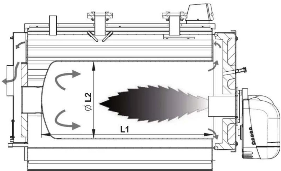
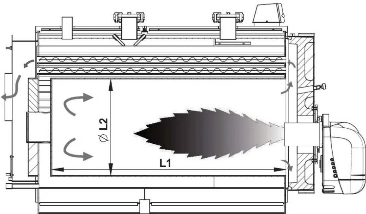
4.2 Operating principle
PREXTHERM RSW N boilers are fitted with a closed cylindrical furnace, in which the flame produced by the burner is reversed peripherally toward the front. From there, the burned gas enters the fire tubes. At the outlet, the gas is collected in the smokebox, and is then sent to the chimney. The combustion chamber is always pressurized during burner operation. For the pressure values, see Table 1, in the column Flue gas side pressure drop. The flue and flue stack fitting must be made in accordance with current standards and legislation, using rigid pipes that are resistant to high temperatures, condensate, and mechanical stress, and are airtight.
text_image
L1 φ L2fig. 1 - 1250N÷1890N
text_image
L1 L2fig. 2 - 2360N÷6000N
4.3 Technical data - Dimensions - Hydraulic connections
| PREXTHERM RSW N 1250 1480 1600 1890 2360 3000 3600 4000 | 4500 5000 6000 | |||||||||||
| Rated power | min. kW | 813 962 1040 1229 1535 1950 2340 2600 2926 3251 3902 | ||||||||||
| max. kW | 1250 1480 1600 1890 2360 3000 3600 4000 4500 5000 6000 | |||||||||||
| Furnace power | min. kW | 884 1046 1128 1336 1668 2113 2536 2819 3165 3515 4215 | ||||||||||
| max. kW | 1359 1608 1736 2054 2565 3250 3900 4334 4868 5407 6483 | |||||||||||
| Total boiler capacity I | 1240 1490 1490 1620 1925 2600 2920 4425 4790 6150 6800 | |||||||||||
| Water side load loss | Dt 10°C mbar | 86 110 115 100 150 145 190 250 280 200 215 | ||||||||||
| Dt 15°C mbar | 40 55 60 45 70 65 90 120 135 85 105 | |||||||||||
| Dt 20°C mbar | 25 32 40 29 42 45 61 70 80 55 65 | |||||||||||
| Flue side load loss | mbar | 6,5 6,5 6,8 7 7,2 7,5 8,2 9,5 10,5 10,8 12 | ||||||||||
| Maximum operating pressure | bar | 6 6 6 6 6 6 6 6 6 6 6 6 6 6 6 6 6 | ||||||||||
| Dry weight | kg | 2250 2650 2700 2850 3900 5300 5800 7500 8000 9600 11500 | ||||||||||
| DIMENSIONS | A | mm | 1450 1530 1530 1530 1610 1800 1800 1980 1980 2180 2180 | |||||||||
| B | mm | 2018 2320 2320 2520 2772 2976 3346 3596 3946 3948 4448 | ||||||||||
| C | mm | 1551 1661 1661 1611 1810 2000 2000 2180 2180 2380 2380 | ||||||||||
| D | mm | 165 165 165 165 / / / / / / / | ||||||||||
| E | mm | 190 190 190 190 210 220 220 240 240 260 260 | ||||||||||
| F | mm | 212 212 212 212 250 250 250 250 250 250 | ||||||||||
| G | mm | 900 1013 1013 1013 1005 1100 1100 1190 1190 1290 1290 | ||||||||||
| H | mm | 670 743 743 743 860 940 940 960 960 1015 1015 | ||||||||||
| I | mm | 2420 2722 2722 2722 3232 3446 3816 4086 4436 4458 4958 | ||||||||||
| L | mm | 90 120 120 120 145 145 145 145 145 145 | ||||||||||
| L1 | mm | 178 199 199 199 195 195 195 195 195 | ||||||||||
| M | mm | 1580 1730 1730 1730 1950 2140 2140 2325 2325 2525 | ||||||||||
| N | mm | 218 220 220 220 462 516 586 536 586 586 586 | ||||||||||
| O | mm | 480 580 580 580 900 950 950 950 950 1050 1050 | ||||||||||
| P | mm | 900 1100 1100 1200 950 1150 1350 1650 1950 1850 2150 | ||||||||||
| Q | mm | 1390 1470 1470 1470 1000 1170 1170 1350 1350 1550 | ||||||||||
| R | mm | 1994 2296 2296 2496 / / / / / / | ||||||||||
| Firebox internal diameter (Fig. 1/2) | L2 | mm | 776 829 829 829 980 1130 1130 1174 1174 1280 1280 | |||||||||
| Firebox length (Fig. 1/2) | L1 | mm | 1860 2180 2180 2380 2650 2750 3100 3350 3750 3750 4170 | |||||||||
| HOT WATER FLOW | T1 | DN | 125 150 150 150 150 200 200 200 200 250 250 | |||||||||
| HOT WATER RETURN | T2 | DN | 125 150 150 150 150 200 200 200 200 250 250 | |||||||||
| EXPANSION TANK CONNECTION | T3 | DN | 3" 100 100 100 100 125 125 125 125 150 150 | |||||||||
| BOILER DRAIN | T4 | DN | 3/4" 1" 1/2 1" 1/2 1" 1/2 1" 1/2 1" 1/2 1" 1/2 1" 1/2 1" 1/2 1" 1/2 | |||||||||
| FLUE GAS OUTLET | T5 | ∅ | 400 450 450 450 450 500 500 600 600 650 650 | |||||||||
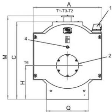
Key
1 Control panel
T2 Central heating return
2 Burner bracket T3 Expansion vessel connection
T4 Boiler drain
3 Smokebox cleaning door
T5 Flue gas outlet
4 Flame inspection window
T6 Burner connection
T1 Central heating feed
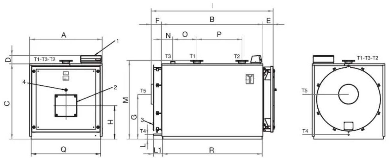
fig. 3 - RSW 1250N÷1890N
text_image
A T1-T3-T2 1 4 M C T6 H 2 Q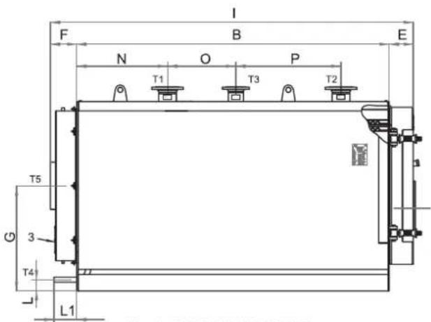
text_image
F I B E N O P T1 T3 T2 T5 3 T4 L1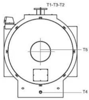
text_image
T1-T3-T2 T5 T4fig. 4 - RSW 2360N÷6000N
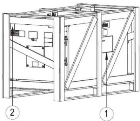
4.4 Identification
The boiler can be identified from the:
- Document envelope (1)
This is applied to the door, and contains:
TECHNICAL MANUAL
WARRANTY CERTIFICATE
LABELS WITH BARCODE
RATING LABEL
CONSTRUCTION CERTIFICATE
-certifying that the water pressure tests have been passed)
- Rating label (2)
This describes the technical specifications and the performance of the appliance. It is included in the document envelope and MUST BE APPLIED by the installer, when installation is complete, to the top front part of one of the side panels of the casing, in a visible position. If the label is lost, contact the Ferroli Technical Service for a duplicate.
natural_image
Technical line drawing of a mechanical enclosure or enclosure frame with internal components and structural supports (no text or symbols)fig. 5
Tampering with or the removal or absence of rating labels or other means enabling the unit to be identified causes problems during installation and maintenance.
5. INSTALLATION
5.1 Packaging
The PREXTHERM RSW model 1250N-1890N boilers are supplied complete with the door and smokebox fitted and insulation on the body, while the casing is contained in a separate cardboard box. The instrument panel is supplied in a cardboard box and positioned inside the combustion chamber. The RSW model 2360N-6000N boilers are supplied complete with insulation and casing. The instrument panel is supplied in a cardboard box and positioned inside the combustion chamber.
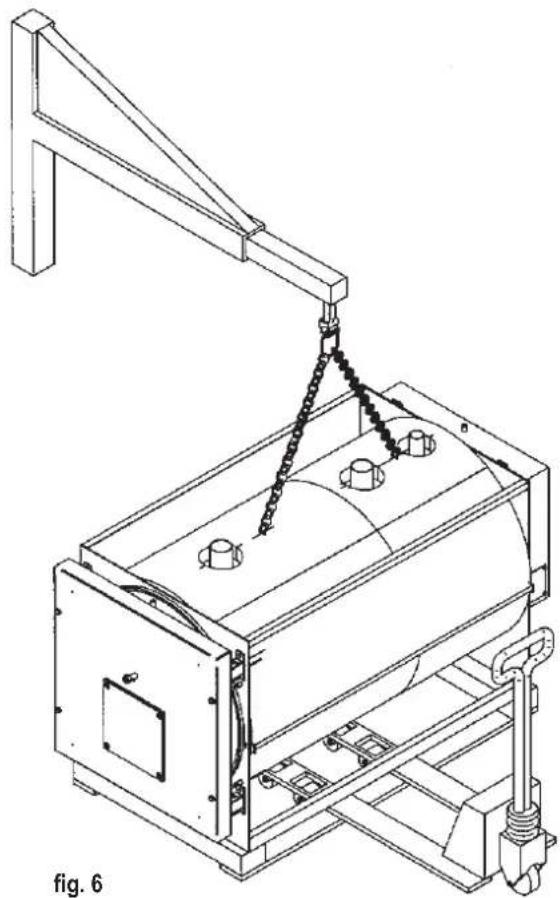
5.2 Handling
The PREXTHERM RSW N boilers are fitted with eyebolts for lifting. Make sure the hoisting equipment used is suitable for the weight being lifted. Before positioning the boiler, remove the wooden base support by unscrewing the fastening screws (Fig. 6).
natural_image
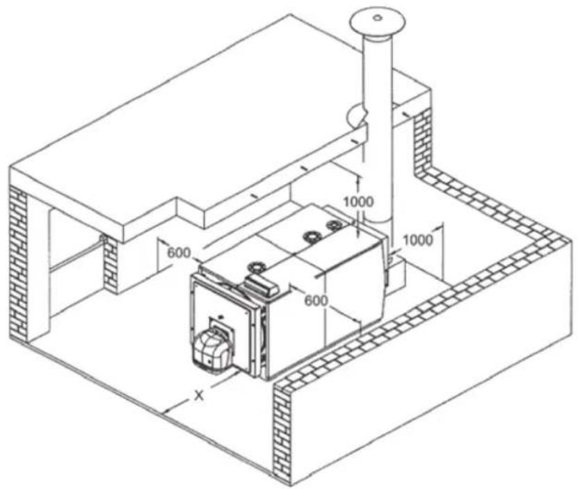
Technical line drawing of a mechanical device with a crane lifting a cylindrical component (no text or symbols)PREXTHERM RSW N boilers must be installed in rooms to be used exclusively for that purpose, in accordance with current technical standards and legislation, and featuring adequately sized ventilation openings. The ventilation openings must be permanent, directly open to the outside, and located in both high and low positions, in accordance with current standards. The location of the ventilation openings and fuel supply, electrical power distribution and lighting circuits must comply with current legal provisions for the type of fuel used. To facilitate the cleaning of the flue gas circuit, space must be left at the front of the boiler, greater than or equal to the length of the boiler body, and no less than 1,300 mm. With the door open 90°, verify that the distance between the door and adjacent wall (X) is at least equal to the length of the burner. The boiler support surface must be perfectly horizontal. A flat cement base is recommended, able to support the full weight of the boiler plus the water content. For the base dimensions, see the R x Q distances (dimension table). If the burner is powered by a fuel gas with a specific weight higher than air, the electrical parts must be located at least 500 mm from the floor. These boilers cannot be installed outdoors because they are not designed to operate outside, and are not equipped with automatic frost protection systems.
INSTALLATION IN OLD SYSTEMS
If the boiler is to be installed in an old system, verify that:
- The chimney is suitable for the temperature of the combustion products, has been calculated and manufactured in accordance with current standards, and is airtight, insulated, and not blocked or choked.
- The electrical system has been installed by qualified personnel, in accordance with current standards.
- The fuel supply line and any tanks have been installed in accordance with current standards.
- The expansion vessel(s) can completely absorb the expansion of the fluid contained in the system.
- The flow-rate, static pressure, and direction of flow of the circulation pumps are suitable.
- The system is clean, free of slime and deposits, vented and watertight.
- A treatment system is available for supply/top-up water (see reference values).
text_image
600 1000 600 1000 Xfig. 7
natural_image
Technical line drawing of a vertical cylindrical device mounted on an electrical enclosure (no text or symbols visible)fig. 8
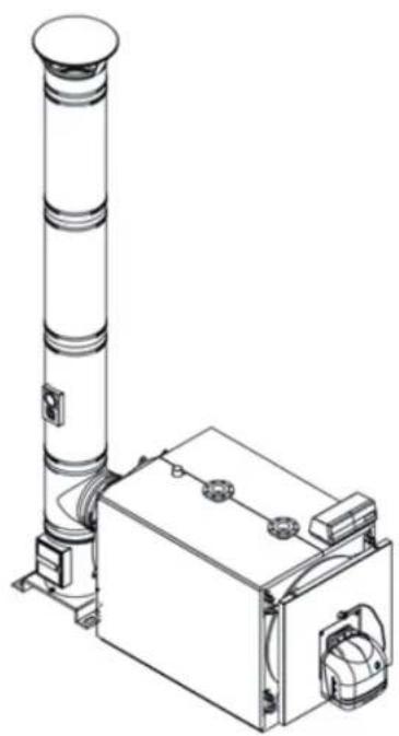
5.4 Discharge of combustion products (Fig. 8)
The flue and flue stack fitting must be made in accordance with current standards and legislation, using rigid pipes that are resistant to high temperatures, condensate, and mechanical stress, and are airtight.
The flue must ensure the minimum negative pressure established by current standards, with "zero" pressure considered at the fitting to the flue. Unsuitable or incorrectly sized flues can increase the noise produced by combustion, cause condensation problems, and negatively affect the combustion parameters. Uninsulated flues are a source of danger. The joint seals must be made with materials that can resist temperatures of at least 250°C. Suitable points for measuring the flue gas temperature and analyzing the products of combustion must be prepared in the connection between the boiler and the flue.
For the cross-section and height of the chimney, refer to current local and national regulations.
5.5 Hydraulic connections
5.5.1 Supply water
The chemical characteristics of the system and top-up water are fundamental for the correct operation and safety of the boiler. The water must be treated using suitable systems. The values shown in the table below can be used as a reference.
TOTAL HARDNESS ppm 10
ALKALINITY mg/l CaCO3 750
PH 8÷9
SILICA ppm 100
CHLORIDES ppm 3500
The water used in the heating system absolutely must be treated in the following cases:
- Very large systems
- Very hard water
- Frequent addition of water to top up the system
If it becomes necessary to partially or completely empty the system, it should be refilled with treated water. To control the volume of water refilled, a meter should be installed on the pipe. The most common issues arising in heating systems are:
- Lime scale deposits
Lime scale accumulates at the points where the wall temperature is highest. Due to their low heat conductivity, lime scale deposits cause a reduction in heat exchange. Even if they're only a few millimeters thick, the heat exchange between the flue gas and the water is limited, which increases the temperature of the parts exposed to the flame and causes cracks in the tube plate.
- Corrosion on the water side
Corrosion of the metal surfaces on the water side of the boiler is caused by the dissolution of iron into its ions. The presence of dissolved gases, particularly oxygen and carbon dioxide, plays an important role in this process. Softened and/or demineralized water provides protection against deposits, but not against corrosion. The water must therefore be treated with corrosion inhibitors.
5.5.2 System feed/return pipes
The dimensions of the feed and return pipes for each boiler model are indicated on the DIMENSIONS table. Make sure the system has a sufficient number of vent openings.
The boiler fittings must not support the weight of the connection pipes to the system. Appropriate supports must be installed for this purpose.
5.5.3 System fill/drain pipe
For filling and draining the boiler, a cock can be connected to fitting T4 on the back (see DIMENSIONS, Fig. 3).
5.5.4 Pipes, expansion vessel and safety valves
PREXTHERM RSW N boilers are suitable for operation with forced water circulation, with the expansion vessel open or closed. An expansion vessel is always required to compensate for the increase in water volume due to heating. In the first case, the height of the hydrostatic column must be at least 3 meters above the boiler body. Its capacity must be sufficient to contain the increase in volume of all water in the system, between the surface of the water in the vessel and the overflow pipe. Tall, narrow vessels are preferable, as they ensure minimum contact between the water surface and the air, thus reducing evaporation. In the second case, the capacity of the closed expansion vessel must be calculated considering:
- the total volume of water contained in the system
- the maximum operating pressure of the system
- the maximum operating pressure of the expansion vessel
- the initial pre-charge pressure of the expansion vessel
- the boiler's maximum operating temperature (the maximum temperature on the thermostat fitted on the panel is 90^ C; use 100^ C to perform this calculation).
The expansion pipe connects the expansion vessel to the system. This pipe will start at the T3 fitting (see the Dimensions table), and must not be fitted with on-off valves. At fitting T3, or within 0.5 m of the first flange on the outlet pipe, install a safety valve suitable for the capacity of the boiler and in compliance with current local standards. No type of shut-off device may be installed between the boiler and the safety valves, and these valves should be set to operate when the maximum permitted operating pressure is exceeded.
5.5.5 Recirculation pump
Condensation of the water vapor contained in the flue gas leaving the boiler (condensate) occurs when the return water temperature is below 50°C. This is significant, particularly when the boiler is turned on in the morning after being off all night. Condensate is acidic and corrosive, and will damage the metal plating on the boiler over time. It is therefore advisable to install a recirculation pump with an anti-condensation feature, to be fitted between the feed and return fittings, upstream of any mixing valve. While the system is operating, the pump must ensure a flow-rate of 20 to 30% of the total. The (anti-condensation) recirculation pump is controlled using the Low-Temperature Thermostat Panel (optional). The bulb for the corresponding thermostat must be fitted at the return (using a sheath that must be added by the installer of that pipe).
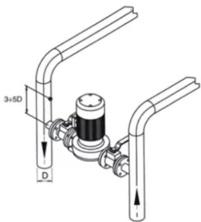
text_image
3+5D Dfig. 9
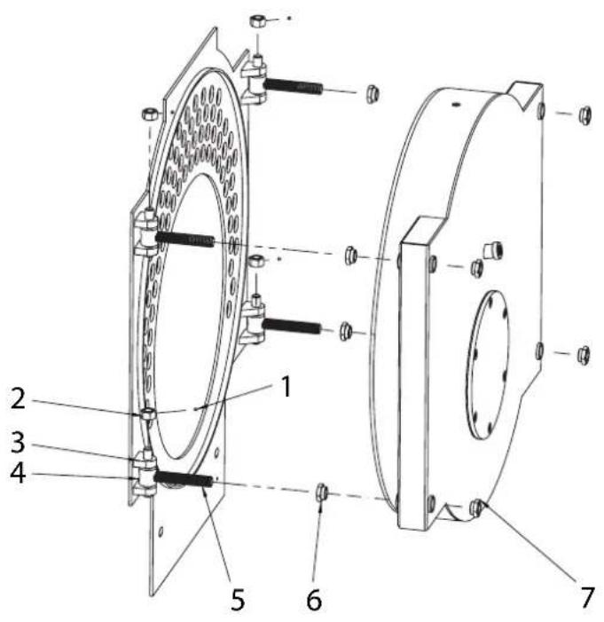
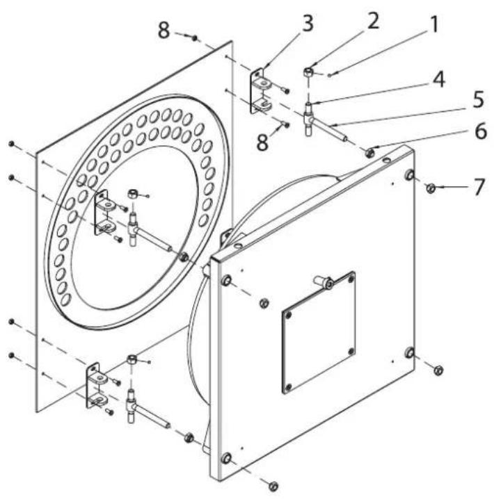
5.6 Adjusting the front door
For PREXTHERM RSW models 1250N÷1890N the door is hinged, fastened and reversed as regards the direction of opening as shown in Fig. 10. The following operations are required:
- The door is supplied with four equal brackets (pos. 3) and hinges.
- To establish the direction of opening, RIGHT or LEFT, unscrew the nut (pos. 7), unscrew and remove the R or L nut (pos. 6), depending on which side the door opens from.
- Height adjustment of the door is performed using the nut (pos. 2); after having completed the adjustments tighten the dowels (pos. 1).
- Longitudinal adjustment is performed using the screw (pos. 8).
text_image
Technical diagram of an industrial machine with numbered components for identificationfig. 10 fig. 11

text_image
Technical diagram of a mechanical assembly with numbered components for identificationKey (Fig. 10)
1 Fastening dowel
2 Door support/adjustment nut
3 Hinge bracket
4 Hinge pin
5 Hinge screw
6 Hinge fastening nut
7 Fastening nut
8 Hinge bracket fastening/adjustment screws and nuts
For PREXTHERM models RSW 2360N÷6000N the door is hinged, fastened and reversed as regards the direction of opening as shown in Fig.
-
The following operations are required:
-
The door is supplied with four equal hinges (pos. 3).
- To establish the direction of opening, RIGHT or LEFT unscrew the nut (pos. 7), unscrew and remove the R or L nut (pos. 6), depending on which side the door opens from.
- Height adjustment of the door is performed using the nut (pos. 2); after having completed the adjustments tighten the dowels (pos. 1).
Key (Fig. 11)
1 Fastening dowel
2 Door support/adjustment nut
3 Hinge bracket
4 Hinge pin
5 Hinge screw
6 Hinge fastening nut
7 Fastening nut
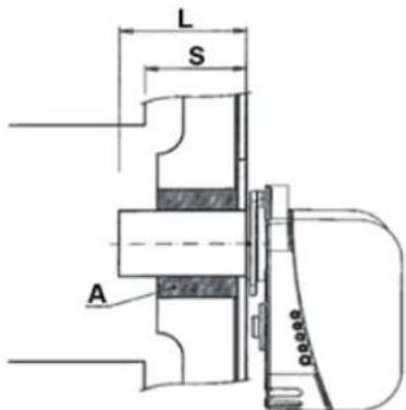
5.7 Assembling the burner (Fig. 12)
The assembly of the burner at the boiler door must ensure perfect tightness for the products of combustion. Once the burner is installed on the boiler, the space between the burner nozzle and the refractory material on the door must be filled with the ceramic fiber padding (A) provided. This prevents the door from overheating, which would result in irreversible warping.
The fuel connections to the burner must be placed so that the boiler door can open completely with the burner installed. It is advisable to place a rigid supporting base under the burner to prevent its full weight from negatively affecting the door.
| Models L min. (mm) L max. (mm) S | ||
| 1250N 320 390 | 248 | |
| 1480N-1830N 3 | 50 420 262 | |
| 2360N 350 420 | 262 | |
| 3000N-3600N 3 | 70 450 272 | |
| 4000N-4500N 4 | 50 500 270 | |
| 5000N-6000N 5 | 00 550 290 | |
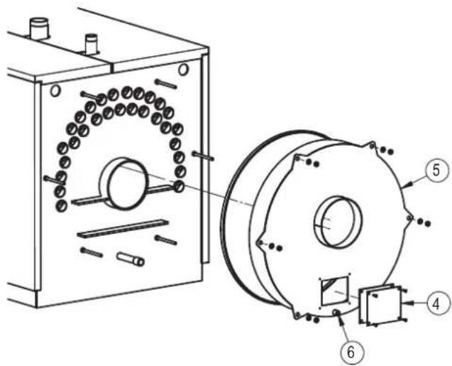
5.8 Connecting the cooling tube to the flame inspection window
The flame inspection window is equipped with a pressure fitting (1). Once the interior screw is loosened, it must be connected to outlet 2 on the burner using a silicone hose or copper pipe. This allows the air blown back by the fan to cool the glass on the window and prevent it from turning black. Failure to connect the hose or pipe to the window can cause the glass to break. When disassembling the window for cleaning, check the condition of the seals, replacing them if necessary. After closing, verify tightness.
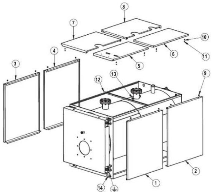
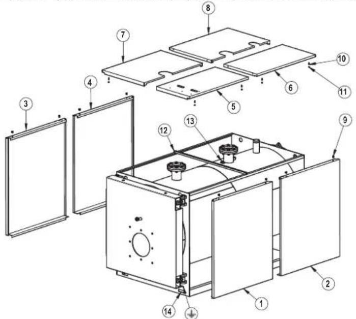
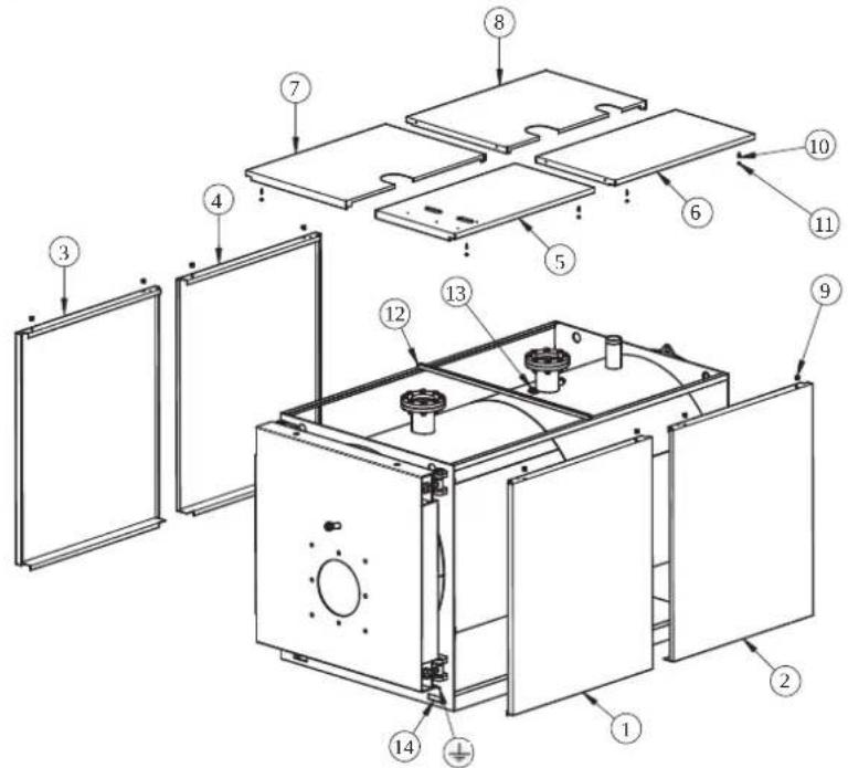
5.9 Assembling the panels, mod. PREXTHERM RSW 1250N÷1890N
a) Carefully position the side panels (pos. 1, 2 - 3 and 4), hooking them onto the supports on the boiler.
b) Assemble the U (pos. 12).
c) Attach the control panel to the top front panel (pos. 5).
d) Rest the top panel (pos. 5), which includes the control panel, against the side panel (pos. 1), which includes springs, closing pins and nuts (pos. 9-10-11).
e) Insert the instrument bulbs in the sheaths (pos. 13) and make the electrical connection from the control panel to the mains, burner, any pumps, etc. It is advisable to insert the probes fully into the sheaths to improve contact.
text_image
L S A 0.0008fig. 12
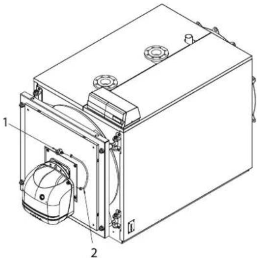
text_image
Technical diagram of a mechanical device with labeled components 1 and 2, showing internal components and wiring.fig. 13
Then secure the capillary tubes with the springs. Close the cover on the electrical panel and pass the burner plug through the openings on the previous plate (pos. 14).
f) Install the top panels (pos. 6-7-8), hooking them onto the side panels (pos. 2-3-4), which include springs, closing pins and nuts (pos. 9-10-11).
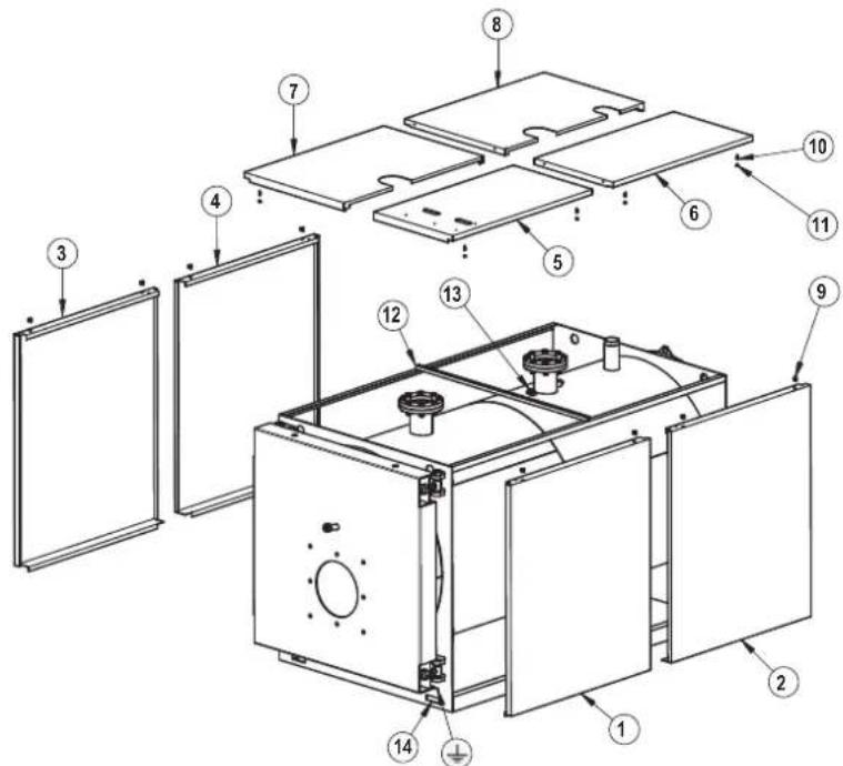
text_image
Exploded view diagram of a microwave oven with numbered components for identificationfig. 14
6. COMMISSIONING
6.1 Preliminary checks
Once the hydraulic, electrical and fuel connections to the boiler have been made, the following must be verified before starting the boiler:
- The expansion vessel and safety valve are properly connected and cannot be blocked in any way.
- The bulbs for the control and minimum safety thermostats and thermometer have been secured in the corresponding sheaths.
- The turbulators have been positioned in all the fire tubes.
- The system is filled with water and completely vented of air.
- The pump or pumps are operating correctly.
- The hydraulic, electrical, safety device, and fuel connections have been performed in accordance with current local and national legislation.
- The burner has been installed according to the instructions in the manufacturer's manual.
- The mains voltage and frequency are compatible with the burner and the boiler's electrical equipment.
- The system is able to absorb the amount of heat that will be produced.
- The recirculation pump is installed as described in section 5.5.5.
6.2 First ignition
After successfully completing the checks indicated in the previous paragraph, the burner may be ignited for the first time. This must be done by a technician authorized by the manufacturer of the burner. The technician will be fully responsible for the field of calibration within the declared and approved output range of the boiler. After opening the fuel on-off cocks and checking that there are no leaks in the supply line, place all switches in the ON position.
The burneris now ready for first ignition, and for the adjustments that may only be made by the authorized technician.
On first ignition, check that the door, burner flange and connections to the chimney are tight, and that there's a slight negative pressure at the base of the flue. The fuel rate must match the information on the boiler's rating card. Under no circumstances may it exceed the declared maximum rated output value. The temperature of the flue gas must never fall below 160°C.
6.3 Shutting down the boiler
- Set the operating thermostat to the minimum value.
- Turn off the power to the boiler and cut off the fuel supply.
- Let the pumps operate until they are stopped by the minimum thermostat.
- Disconnect the power to the electrical panel.
7. MAINTENANCE
7.1 General instructions
Periodic maintenance is essential for the safety, efficiency, and long life of the appliance.
All operations must be carried out by qualified personnel. Before performing any cleaning or maintenance operations, the fuel supply must be cut off after first shutting off the power.
For proper boiler operation and maximum efficiency, the combustion chamber, fire tubes and smokebox must be cleaned regularly.
7.2 Routine maintenance
Maintenance must be scheduled based on the fuel used, number of ignitions, system characteristics, etc. Maintenance intervals can therefore not be determined in advance.
As a reference, we recommend the following cleaning intervals, depending on the fuel:
- Gas boilers: Once a year
- Gas oil boilers: Twice a year
In any case, local maintenance standards must be observed.
During routine maintenance, remove the turbulators and then brush the tube bundle and furnace. Remove the deposits accumulated in the smokebox through the open inspection doors. For more thorough cleaning, remove the rear smokebox. If worn, replace the flue gas seal. Check that the condensate drain is not blocked. Make sure the control and measurement devices on the boiler are working correctly.
On this occasion, record the amount of top-off water used. After analyzing the water, perform a preventive descaling.
After repeated fills, the calcium and magnesium salts dissolved in the water will produce deposits in the boiler, cause the metal plates to overheat, and may cause damage that is not attributable to materials or workmanship, and is therefore not covered by the warranty. After performing cleaning and maintenance operations and the next ignition, check the tightness of the door and smokebox. In the event of combustion leaks, replace the corresponding gasket.
The operations performed must be recorded in the system logbook.
7.3 Special maintenance
Special maintenance must be carried out at the end of the season or for extended shutdowns.
All of the operations described in the previous section must be performed, in addition to the following:
- Check the condition of the turbulators for wear.
- After cleaning the flue gas circuit, wipe with a rag dipped in a diluted caustic soda solution. After letting it dry, wipe all surfaces with a rag dipped in oil.
- Hygroscopic substances (quicklime, silica gel in small containers) should be placed inside the furnace, which must then be closed hermetically so air cannot enter.
- Do not empty the system or boiler.
- Protect the screws, nuts and pins on the door with graphite grease.
The operations performed must be recorded in the maintenance logbook.
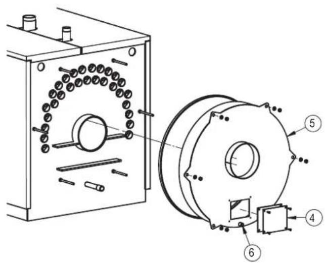
7.4 Cleaning the boiler
To clean the boiler, proceed as follows:
- The boiler comes with a brush for cleaning the fire tubes.
- Open the front door (1) and remove the turbulators (2).
- Clean the inside surfaces of the combustion chamber and the flue gas path using a brush (3) or other suitable implement.
- Remove the deposits accumulated in the smokebox through the open cleaning door (4). For more thorough cleaning, remove the smokebox (5) and replace the gasket before reassembling.
- Check periodically that the condensate drain (6) is not blocked.
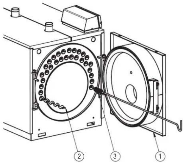
text_image
Technical diagram of a mechanical device with labeled components, showing internal components and assembly steps.fig. 15

text_image
Technical diagram of a mechanical assembly with labeled components, showing internal components and a circular component.fig. 16
7.5 Checking boiler operation
Before starting the boiler and running the functional tests, check that:
- The turbulators are inside the exchanger tubes.
- The cocks on the water circuit and fuel line are open.
- There is fuel available.
- The expansion vessel is suitably filled.
- The pressure of the water circuit, when cold, is over 1 bar and under the maximum limit for the boiler.
- The water circuits have been vented.
- The electrical connections to the mains power and components (burner, pump, control panel, thermostats, etc.) have been completed.
- The phase-neutral connection must be strictly observed, and grounding is mandatory.
After completing the steps described above, the following operations are necessary to start the boiler:
- If the system is equipped with a temperature controller or timer-thermostat, check that they are on.
- Set the room timer-thermostat(s) or temperature controller to the desired temperature.
- Place the main system switch in the "on" position.
- Set the boiler thermostat located on the control panel.
- Place the main switch on the control panel in the "on" position and check that the green indicator light comes on.
The boiler will run the ignition phase, and will remain on until the set temperatures have been reached. If problems occur during ignition or operation, the boiler will "LOCKOUT," as signaled by the red light on the burner and the red indicator on the control panel. After a "LOCKOUT," wait about 30 seconds before resetting the ignition conditions. To reset the ignition conditions, press the burner "button/light" and wait for the flame to ignite. If this operation fails, it can be repeated a maximum of 2 or 3 times. Then check:
- The instructions manual for the burner.
- The section "CHECKING BOILER OPERATION."
- The electrical connections shown on the diagram next to the control panel.
Once the boiler has started, check that it stops and starts again:
- Adjust the setting on the boiler thermostat.
- Operate the main switch on the control panel.
- Set the room thermostat, timer, or temperature controller.
- Check that the pumps are not blocked and rotate correctly.
- Check that the boiler shuts down completely by operating the main system switch.
If all conditions are correct, restart the appliance, check the combustion (flue gas analysis), fuel rate, and tightness of the gaskets on the door and smokebox.
7.6 Checking burner operation
- Check the instructions manual for the burner.
- Follow all local regulations and standards with regard to burner maintenance.
7.7 Troubleshooting
The following is a list of the main faults and problems that may occur during boiler operation, specifying possible causes and solutions.
| FAULT | |||
| THE BOILER IS EASILY SOILED | |||
| CAUSE: Burner poorly | adjusted SOLUTION: Check the burner adjustment (flue gas analysis) | ||
| Flue blocked Clean the flue gas path and the flue | |||
| Burner air intake path dirty Clean the burner air intake | |||
| THE BOILER DOES NOT REACH THE SET TEMPERATURE | |||
| CAUSE: Boiler body dirty SOLUTION: Clean the flue gas path | adjustments | ||
| Check the set temperature | |||
| BOILER THERMAL SAFETY SHUTDOWN WITH INDICATOR LIGHT ON THE CONTROL PANEL | |||
| CAUSE: Control thermostat SOLUTION: Check correct operation | |||
| Check the set temperature | |||
| Check the electrical wiring | |||
| Check the probe bulbs | |||
| Check the vent valve | |||
| THE BOILER REACHES THE SET TEMPERATURE, BUT THE CENTRAL HEATING SYSTEM IS COLD | |||
| CAUSE: Air present in the system SOLUTION: Vent the system | |||
| Reset the pump | |||
| Check the set temperature | |||
| ODOR OF UNBURNED SUBSTANCES | |||
| CAUSE: Flue gas leaking into the environment SOLUTION: Check that the boiler body is clean | |||
| Check that the flue is clean | |||
| Check the tightness of the boiler and flue | |||
| FREQUENT ACTIVATION OF THE SAFETY VALVE | |||
| CAUSE: System circuit pressure SOLUTION: Check the fill pressure | |||
text_image
F I B E N O P T1 T3 T2 T5 3 T4 L1
text_image
T1-T3-T2 T5 T4fig. 4 - RSW 2360N÷6000N
4.4 Identification
- Plaquette technique (2)
natural_image
Technical line drawing of a mechanical enclosure or enclosure with labeled components (no text or symbols present)fig. 5
natural_image
Technical line drawing of a mechanical device with a crane lifting a cylindrical component (no text or symbols)5.3 Local d'installation (Fig. 7)
natural_image
Technical line drawing of a vertical cylindrical device mounted on an electrical box (no text or symbols visible)fig. 8
DURETÉ TOTALE ppm 10
ALCALINITÉ mg/l CaCO3 750
PH 8÷9
SILICE ppm 100
CHLORURES ppm 3500
text_image
Technical diagram of a mechanical device with numbered components for identificationfig. 10 fig. 11

text_image
Technical diagram of a mechanical assembly with numbered components for identificationLégende (Fig. 10)
natural_image
Technical line drawing of a mechanical device with labeled components (no text or symbols present)fig. 13
text_image
Exploded view diagram of a refrigerator internal structure with numbered componentsfig. 14
6. MISE EN MARCHE
text_image
Technical diagram of a mechanical device with labeled components, showing internal components and assembly steps.fig. 15

text_image
Technical diagram of a mechanical assembly with labeled components, showing a housing and a circular component with numbered parts.fig. 16
text_image
F I B E N O P T1 T3 T2 T5 G 3 T4 L1
text_image
T1-T3-T2 T5 T4рис. 4 - RSW 2360N÷6000N
4.4 Идентификация
natural_image
Technical line drawing of a mechanical enclosure or enclosure frame with internal components and structural supports (no text or symbols)рис. 5
natural_image
Technical line drawing of a mechanical device with a crane lifting a cylindrical component (no text or symbols)natural_image
Technical line drawing of a vertical cylindrical device mounted on an electrical enclosure (no text or symbols visible)рис. 8
text_image
Technical diagram of a mechanical assembly with numbered components for identificationрис. 10 рис. 11

text_image
Technical diagram of a mechanical assembly with numbered components for identificationnatural_image
Technical line drawing of a mechanical device with labeled components (no text or symbols present)рис. 13
text_image
Exploded view diagram of a refrigerator with numbered components for identificationрис. 14
text_image
Technical diagram of a mechanical device with labeled components, showing internal components and assembly steps.рис. 15
text_image
Technical diagram of a mechanical assembly with labeled components, showing internal components and a circular component.рис. 16