
FZ4 - Heating controller FERROLI - Free user manual and instructions
Find the device manual for free FZ4 FERROLI in PDF.
| Product Type | Multi-zone heating controller |
| Brand | Ferroli |
| Model | FZ4 (FZ4B) |
| Dimensions (W x H x D) | 207 x 163 x 54 mm |
| Weight | 0.5 kg (estimated) |
| Power supply | 230 VAC +10% / -15%, 50 Hz |
| Power consumption | 5 VA (no load) |
| Number of zones | Up to 3 direct or mixed zones, + DHW tank |
| Supported zone types | Direct, mixed, DHW tank |
| Generator communication | OpenTherm (communicating) or ON/OFF via relay board SK16504 |
| Sensor inputs | 4 NTC inputs (T1 to T4) for outdoor sensor, flow, tank |
| Relay outputs | 7 relays 5A @ 250VAC for pumps, valves, etc. |
| Fuses | 2 x 2A fast 5x20, 250VAC (FH01, FH02) |
| Operating ambient temperature | -10°C to +60°C |
| Storage temperature | -25°C to +80°C |
| Max ambient humidity | 90% at 40°C |
| Mounting | Wall-mounted |
| Automatic configuration | Yes, by Autoconfig button |
| Additional functions | FH mode, pump and valve anti-block, legionella protection, summer/winter mode |
| Maintenance and cleaning | Clean with a dry cloth, do not use abrasive products |
| Safety | Fuses, safety thermostat, short-circuit protection |
| Spare parts and repairability | Outdoor sensor (ref. 013018X0), NTC sensor (1KWMA11W or 043005X0), relay board SK16504, fuses |
| General information | 292-page manual available in multiple languages |
Frequently Asked Questions - FZ4 FERROLI
User questions about FZ4 FERROLI
0 question about this device. Answer the ones you know or ask your own.
Ask a new question about this device
Download the instructions for your Heating controller in PDF format for free! Find your manual FZ4 - FERROLI and take your electronic device back in hand. On this page are published all the documents necessary for the use of your device. FZ4 by FERROLI.
USER MANUAL FZ4 FERROLI
Use and installation instructions
9.1 DISPLAY LCD SPENTO....61
2. INSTALLATION....66
2.1 ASSEMBLY....66
2.2 INSTALLATION....66
2.3 ASSIGNING OF TERMINALS 67
3. FIRST STARTUP (AUTOCONFIGURATION)......82
4. OPERATION 83
5. "STAND ALONE 1" CONFIGURATIONS....84
5.1 "ONE DIRECT ZONE – NO EXTERNAL SENSOR" 84
5.2 "ONE DIRECT ZONE – WITH EXTERNAL SENSOR" 84
5.3 "TWO DIRECT ZONES – NO EXTERNAL SENSOR" 85
5.4 "TWO DIRECT ZONES – WITH EXTERNAL SENSOR" 85
5.5 "THREE DIRECT ZONES - NO EXTERNAL SENSOR" 85
5.6 "THREE DIRECT ZONES – WITH EXTERNAL SENSOR" 86
5.7 "ONE MIXED ZONE - NO EXTERNAL SENSOR" 86
5.8 "ONE MIXED ZONE - WITH EXTERNAL SFNSOR" 87
5.9 "TWO MIXED ZONES - NO EXTERNAL SENSOR" 88
5.10 "TWO MIXED ZONES – WITH EXTERNAL SENSOR" 88
5.11 "ONE MIXED ZONE AND ONE DIRECT ZONE - NO EXTERNAL SENSOR" 89
5.12 "ONE MIXED ZONE AND ONE DIRECT ZONE - WITH EXTERNAL SENSOR" 89
5.13 "ONE MIXED ZONE AND TWO DIRECT ZONES - NO EXTERNAL SENSOR" 89
5.14 "ONE MIXED ZONE AND TWO DIRECT ZONES - WITH EXTERNAL SENSOR" 90
5.15 "TWO MIXED ZONES AND ONE DIRECT ZONE - NO EXTERNAL SENSOR" 90
5.16 "TWO MIXED ZONES AND ONE DIRECT ZONE – WITH EXTERNAL SENSOR" 91
5.17 "ONE HOT WATER TANK" 92
5.18 "ONE DIRECT ZONE AND ONE HOT WATER TANK - NO EXTERNAL SENSOR" 92
5.19 "ONE DIRECT ZONE AND ONE HOT WATER TANK – WITH EXTERNAL SENSOR" 93
5.20 "TWO DIRECT ZONES AND ONE HOT WATER TANK - NO EXTERNAL SENSOR" 93
5.21 "TWO DIRECT ZONES AND ONE HOT WATER TANK - WITH EXTERNAL SENSOR" 94
5.22 "THREE DIRECT ZONES AND ONE HOT WATER TANK - NO EXTERNAL SENSOR" 94
5.23 "THREE DIRECT ZONES AND ONE HOT WATER TANK – WITH EXTERNAL SENSOR". 95
5.24 "ONE MIXED ZONE AND ONE HOT WATER TANK - NO EXTERNAL SENSOR" 96
5.25 "ONE MIXED ZONE AND ONE HOT WATER TANK – WITH EXTERNAL SENSOR" 97
5.26 "ONE MIXED ZONE, ONE DIRECT ZONE AND ONE HOT WATER TANK - NO EXTERNAL SENSOR" 97
5.27 "ONE MIXED ZONE, ONE DIRECT ZONE AND ONE HOT WATER TANK – WITH EXTERNAL SENSOR" 98
6 "STAND ALONE 2" CONFIGURATIONS....99
6.1 "ONE DIRECT ZONE - NO EXTERNAL SENSOR....99
6.2 "ONE DIRECT ZONE – WITH EXTERNAL SENSOR" 100
6.3 "TWO DIRECT ZONES - NO EXTERNAL SENSOR" 100
6.4 "TWO DIRECT ZONES - WITH EXTERNAL SENSOR" 101
6.5 "THREE DIRECT ZONES - NO EXTERNAL SENSOR" 101
6.6 'THREE DIRECT ZONES - WITH EXTERNAL SENSOR' 101
6.7 "ONE MIXED ZONE – NO EXTERNAL SENSOR" 102
6.8 "ONE MIXED ZONE - WITH EXTERNAL SENSOR" 103
6.9 "TWO MIXED ZONES – NO EXTERNAL SENSOR" 104
6.10 *TWO MIXED ZONES – WITH EXTERNAL SENSOR* 104
6.11 "ONE MIXED ZONE AND ONE DIRECT ZONE - NO EXTERNAL SENSOR" 105
6.12 "ONE MIXED ZONE AND ONE DIRECT ZONE – WITH EXTERNAL SENSOR" 105
6.13 "ONE MIXED ZONE AND TWO DIRECT ZONES - NO EXTERNAL SENSOR" 105
6.14 "ONE MIXED ZONE AND TWO DIRECT ZONES - WITH EXTERNAL SENSOR" 106
6.15 "TWO MIXED ZONES AND ONE DIRECT ZONE - NO EXTERNAL SENSOR" 106
6.16 "TWO MIXED ZONES AND ONE DIRECT ZONE - WITH EXTERNAL SENSOR" 107
6.17 "ONE HOT WATER TANK" 108
6.18 "ONE DIRECT ZONE AND ONE HOT WATER TANK - NO EXTERNAL SENSOR" 108
6.19 "ONE DIRECT ZONE AND ONE HOT WATER TANK – WITH EXTERNAL SENSOR" 109
6.20 "TWO DIRECT ZONES AND ONE HOT WATER TANK - NO EXTERNAL SENSOR" 109
6.21 "TWO DIRECT ZONES AND ONE HOT WATER TANK – WITH EXTERNAL SENSOR" 110
6.22 "THREE DIRECT ZONES AND ONE HOT WATER TANK – NO EXTERNAL SENSOR" 111
6.23 "THREE DIRECT ZONES AND ONE HOT WATER TANK - WITH EXTERNAL SENSOR". 112
6.24 "ONE MIXED ZONE AND ONE HOT WATER TANK - NO EXTERNAL SENSOR" 112
6.25 "ONE MIXED ZONE AND ONE HOT WATER TANK – WITH EXTERNAL SENSOR" 113
6.26 "ONE MIXED ZONE, ONE DIRECT ZONE AND ONE HOT WATER TANK - NO EXTERNAL SENSOR" 114
6.27 "ONE MIXED ZONE, ONE DIRECT ZONE AND ONE HOT WATER TANK – WITH EXTERNAL SENSOR" 115
7 "COMMUNICATING" CONFIGURATIONS....115
7.1 "COMMUNICATING" CONFIGURATIONS WITH DHW (INTEGRATED IN BOILER) 115
8 SERVICE MENU 115
"TS" - TRANSPARENT PARAMETERS MENU 116
"IN" - INFORMATION MENU 116
"HI" - HISTORY MENU 116
"RE" - HISTORY RESET 117
9 INDICATIONS DURING OPERATION 117
9.1 LCD DISPLAY OFF 117
10 ADDITIONAL FUNCTIONS.... 117
10.1 FH MODE 117
10.2 EQUAL SETTINGS FOR EACH ZONE (TSP30) 117
10.3 PUMP ACTIVATION WITH CARD IN STANDBY (TSP34) 117
10.4 HEATING DELIVERY PROBE ENABLING (TSP35)....117
10.5 OPERATION WITH BOILER IN FAULT STATUS (TSP36)....117
10.6 LEGIONELLA PROTECTION (TSP37) 117
10.7 BOILER SUMMER/WINTER MODE (TSP38) 117
10.8 ANTIBLOCKING....118
10.9 SENSOR CHARACTERISTICS 118
10.10 USER SETTINGS....118
10.11 EXTERNAL PROBE/ SLIDING TEMPERATURE....118
TABLE DES MATIÈRES
1. VUE D'ENSEMBLE....120
VUE EXTÉRIEURE ET DIMENSIONS BOÎTIER....120
VUE INTERIEURE CARTE 120
DESCRIPTION GÉNÉRALE ....121
CONTENU DU KIT 122
DONNÉES TECHNIQUES 122
2. INSTALLATION....122
2.1 MONTAGE 122
2.2. INSTALLATION....122
2.3 BORNAGE 123
3. PREMIÈRE MISE EN MARCHE (CONFIGURATION AUTOMATIQUE) 138
4. FONCTIONNEMENT....139
2. INSTALLATION....236
2.1 MONTAGE 236
2.2 INSTALLATION 236
2.3 ZUWEISUNG DER KLEMMEN 237
3. ERSTE INBETRIEBNAHME (AUTOKONFIGURATION....252
4. BETRIEB....253
5. KONFIGURATIONEN "STAND-ALONE 1" 254
5.1 "EIN DIREKTER HEIZKREIS - KEIN AUSSENSENSOR" 254
5.2 "EIN DIREKTER HEIZKREIS - MIT AUSSENSENSOR" 254
5.3 "ZWEI DIREKTE HEIZKREISE – KEIN AUSSENSENSOR" 255
5.4 "ZWEI DIREKTE HEIZKREISE - MIT AUSSENSENSOR" 255
5.5 "DREI DIREKTE HEIZKREISE - KEIN AUSSENSENSOR" 256
5.6 "DREI DIREKTE HEIZKREISE - MIT AUSSENSENSOR" 256
5.7 "EIN GEMISCHTER HEIZKREIS - KEIN AUSSENSENSOR" 256
5.8 "EIN GEMISCHTER HEIZKREIS - MITAUSSENSENSOR" 257
5.9 'ZWEI GEMISCHTE HEIZKREISE - KEIN AUSSENSENSOR' 258
5.4 "ZWEI GEMISCHTE HEIZKREISE - MIT AUSSENSENSOR" 259
fig. 3
![graph TD A["Input"] --> B{Decision} B --> C["Output"] B --> D["Feedback"] D --> E["Output"] style B fill:#fff,stroke:#000 style E fill:#fff,stroke:#000](/content/2026/03/549582/images/cdb696957dc96184b2eaabca4749c042e42f6ef0911b5c7d55b61d9b120d2ffb.jpg)
fi g. 4
fi g. 16
5.2.1 Termostato on/off
5.18.1 Termostato on/off
5.20.1 Termostato on/off
5.22.1 Termostato on/off
5.24.1 Termostato on/off
5.26.1 Termostato on/off
6.1.1 Termostato on/off
Pompa di zona
6.2.1 Termostato on/off
6.18.1 Termostato on/off
6.20.1 Termostato on/off
6.22.1 Termostato on/off
6.24.1 Termostato on/off
6.26.1 Termostato on/off
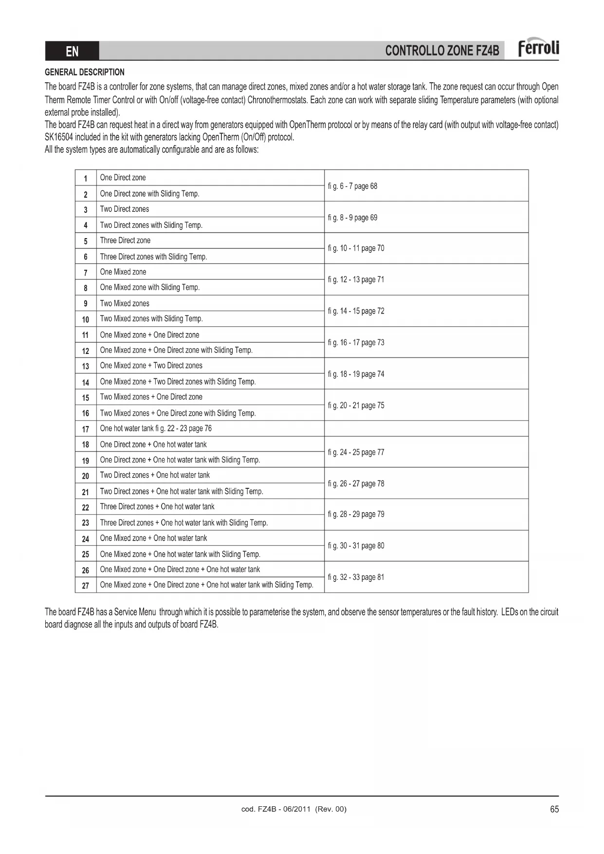
OFFSET = 20
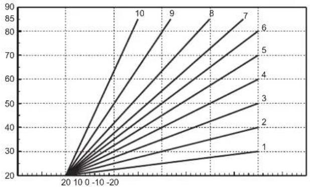
IMPOSTABILE SEPARATAMENTE PER OGNI SINGOLA ZONA:
SI SCELGONO LE CURVE (DA 1 A 10) AI PARAMETRI:
P05 = CURVA ZONA 1
P11 = CURVA ZONA 2
P17 = CURVA ZONA 3
SI SCEGLIE L'OFFSET (SPOSTAMENTO PARALLELO) PER OGNI SINGOLA ZONA AI PARAMETRI:
P06 = OFFSET ZONA 1
P12 = OFFSET ZONA 2
P18 = OFFSET ZONA 3
OFFSET = 40
EXTERNAL VIEW AND BOX DIMENSIONS

fi g. 1
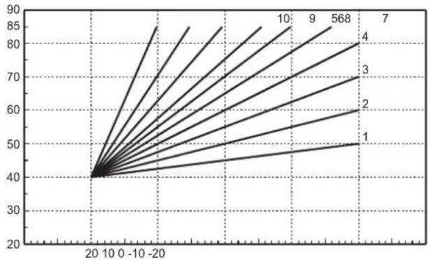
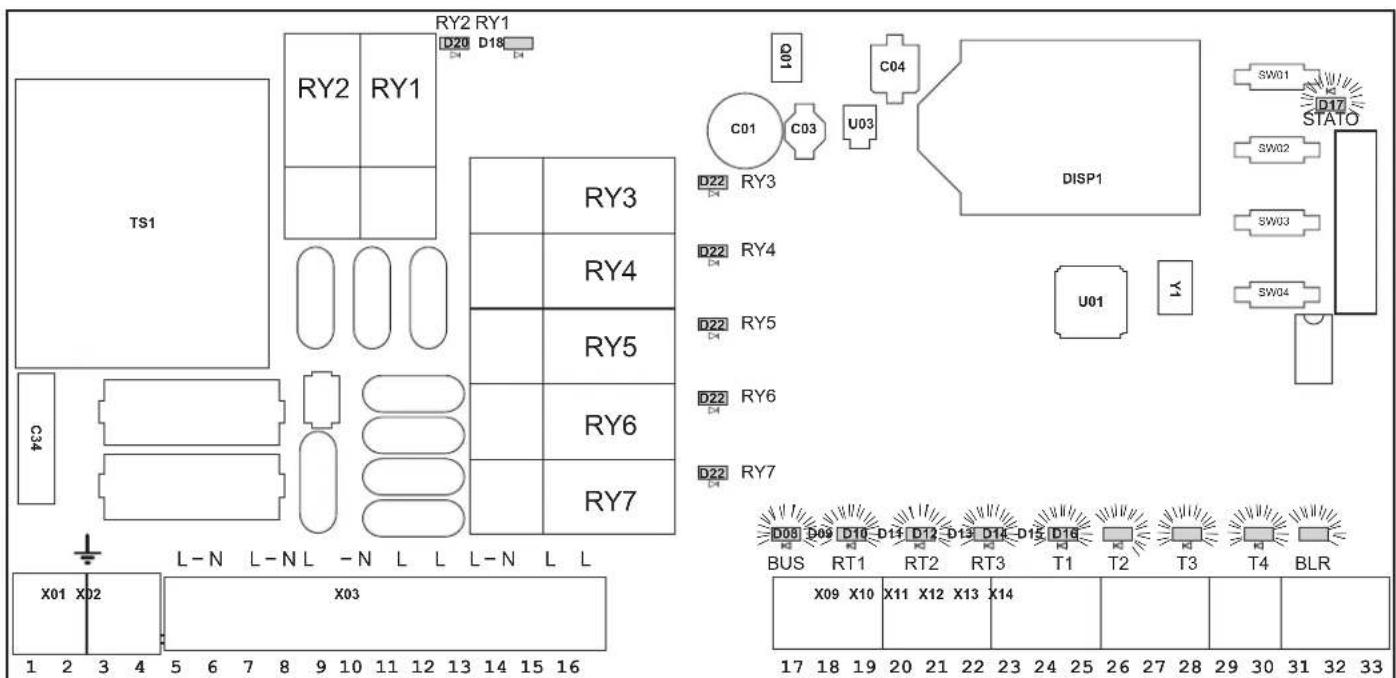
BOARD INTERNAL VIEW
fig.2
Key
1 LCD
5 AUTOCONFIGURATION button
2 + button
6 Fuse "FH01" board FZ4 loads (relay)
3 - button
7 Fuse "FH02" board FZ4
4 OK button
8 Connector X15 for relay card SK16504
GENERAL DESCRIPTION
The board FZ4B is a controller for zone systems, that can manage direct zones, mixed zones and/or a hot water storage tank. The zone request can occur through Open Therm Remote Timer Control or with On/off (voltage-free contact) Chronothermostats. Each zone can work with separate sliding Temperature parameters (with optional external probe installed).
The board FZ4B can request heat in a direct way from generators equipped with OpenTherm protocol or by means of the relay card (with output with voltage-free contact) SK16504 included in the kit with generators lacking OpenTherm (On/Off) protocol.
All the system types are automatically configurable and are as follows:
| 1 | One Direct zone | fi g. 6 - 7 page 68 |
| 2 | One Direct zone with Sliding Temp. | |
| 3 | Two Direct zones | fi g. 8 - 9 page 69 |
| 4 | Two Direct zones with Sliding Temp. | |
| 5 | Three Direct zone | fi g. 10 - 11 page 70 |
| 6 | Three Direct zones with Sliding Temp. | |
| 7 | One Mixed zone | fi g. 12 - 13 page 71 |
| 8 | One Mixed zone with Sliding Temp. | |
| 9 | Two Mixed zones | fi g. 14 - 15 page 72 |
| 10 | Two Mixed zones with Sliding Temp. | |
| 11 | One Mixed zone + One Direct zone | fi g. 16 - 17 page 73 |
| 12 | One Mixed zone + One Direct zone with Sliding Temp. | |
| 13 | One Mixed zone + Two Direct zones | fi g. 18 - 19 page 74 |
| 14 | One Mixed zone + Two Direct zones with Sliding Temp. | |
| 15 | Two Mixed zones + One Direct zone | fi g. 20 - 21 page 75 |
| 16 | Two Mixed zones + One Direct zone with Sliding Temp. | |
| 17 | One hot water tank fi g. 22 - 23 page 76 | |
| 18 | One Direct zone + One hot water tank | fi g. 24 - 25 page 77 |
| 19 | One Direct zone + One hot water tank with Sliding Temp. | |
| 20 | Two Direct zones + One hot water tank | fi g. 26 - 27 page 78 |
| 21 | Two Direct zones + One hot water tank with Sliding Temp. | |
| 22 | Three Direct zones + One hot water tank | fi g. 28 - 29 page 79 |
| 23 | Three Direct zones + One hot water tank with Sliding Temp. | |
| 24 | One Mixed zone + One hot water tank | fi g. 30 - 31 page 80 |
| 25 | One Mixed zone + One hot water tank with Sliding Temp. | |
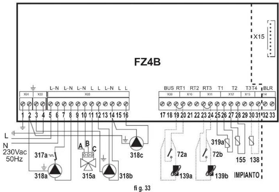
| 26 | One Mixed zone + One Direct zone + One hot water tank | fi g. 32 - 33 page 81 |
| 27 | One Mixed zone + One Direct zone + One hot water tank with Sliding Temp. |
The board FZ4B has a Service Menu through which it is possible to parameterise the system, and observe the sensor temperatures or the fault history. LEDs on the circuit board diagnose all the inputs and outputs of board FZ4B.
| KIT LIST TECHNICAL DATA | |
| Q. Description | |
| 1 | Board FZ4B |
| 2 | NTC probe L=2500mm |
| 1 | Bag for screws |
| 6 | Cable clamp |
| 12 | Phillips self-tapping screw 3.5x19 UNI6954 |
| 2 x 2 | Plugs D.5x25 |
| 2 x 2 | Flathead screw 4x30 |
| 1 | Instruction manualFZ4B |
| 1 | Card SKI6504 |
| Room temp. |
| Operation: -10°C ÷ +60°C |
| Storage and transport -25°C ÷ +80°C |
| Max. room humidity 90% at 40°C |
| Installation: |
| Wall |
| Power supply range: |
| 230Vac +10% -15%, 50Hz |
| Total current absorbed: |
| 5VA @ 230Vac (no load) |
| 230Vac output characteristics: |
| Output relay nominal current = 5A@250Vac (max. permissible load: 1A 230Vac cos φ 0.7) |
| Fuse characteristics: |
| 2 x 250Vac 2A fast 5x20 |
2. INSTALLATION
2.1 ASSEMBLY

Attention!
Before opening the enclosure, always make sure the mains voltage is disconnected.
Assembly must be carried out only in a closed and dry place. To ensure proper operation, make there are no strong electromagnetic fields in the place of installation. The controller must be separated from the power mains by means of a supplementary device (with a disconnection distance of at least 3 mm on all poles), or a disconnecting device complying with the regulations. During installation make sure the power supply connection cable and the probe cables remain separated.
2.2 INSTALLATION
Before installation, remove the front part of the box, prising with a screwdriver at point 1 (fig.3); then lift the front part of the box as indicated in point 2 (fi g.3):
Fix the back of the zone control (fig.4) to the wall with the set of screws supplied.
Carry out the wiring according to the diagrams given in the following section. Close everything, repeating the previous steps in reverse order.
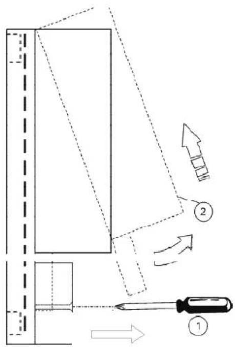
fig. 3
![graph TD A["Device"] --> B{Symbol} B --> C["Node"] B --> D["Node"] B --> E["Node"] B --> F["Node"] style B fill:#f9f,stroke:#333,stroke-width:2px](/content/2026/03/549582/images/06d18aa53368692e3d2e7ba3ff49fef596039a51b7ca4430426ec23b2852c59c.jpg)
fi g. 4
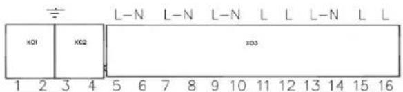
2.3 ASSIGNING OF TERMINALS
After switching off the power to the boiler, carry out the wiring using the terminal block on the zone control unit (fig.5).
fi g. 5
For the low voltage connections (terminals: 17-33) use cables of section 2.5mm2 max., making sure their path is not the same as that of the mains power cables. The max. length of cables must not exceed 50 m . For the connections to mains voltages (terminals 5-16) and Earth (terminals 1-4), use cables of section 4.0mm2 max.
The permanent power supply of the zone controller must be connected to terminals 5(L) and 6(N); the cable for communication with the boiler board (OpenTherm Remote Timer Control terminals) must be connected to terminals 32 and 33 (BLR); a possible External Probe (optional) must be connected to terminals 30 and 31 (T4) if the connection is not available on the boiler board. For the rest of the wiring, use the diagrams given in the following sections.
Room adjustment can occur by means of the Remote Timer Control (OpenTherm) and/or Room Chronothermostats (only with voltage-free contact). In any case, make sure to use at least one Remote Timer Control to facilitate the user and installer settings.
Generator demand
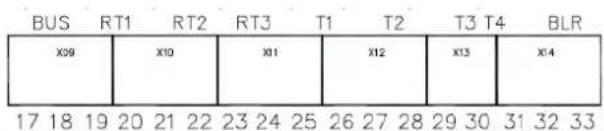
Regardless of the type of layout to be managed, the zone controller can demand heat from the generator in 3 different ways:
Therefore, first of all it is necessary to select one of these 3:
1 - Communicating: Generator equipped with Opentherm protocol
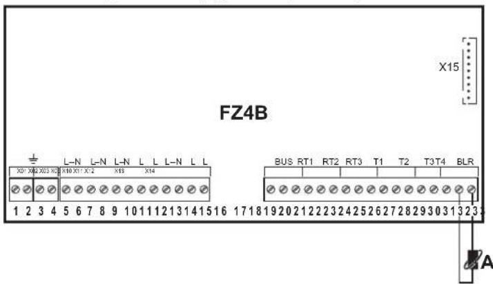
Carry out the "boiler" A connection, disconnecting the relay card (output with voltage-free contact) code SK16504.
A - Connect to boiler Opentherm Remote Timer Control (139)
2 - Stand alone 1: Generator without Opentherm protocol (ON/OFF)
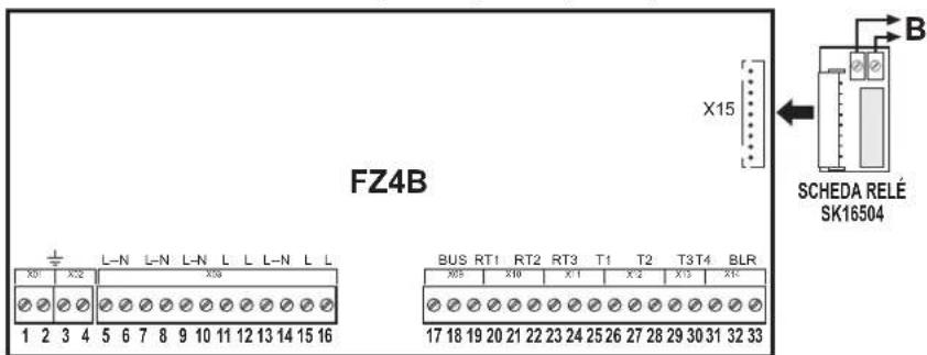
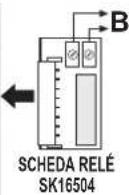
Carry out the "boiler" B connection, connecting the relay card (output with voltage-free contact) code SK16504
B - Connect to boiler on/off room Thermostat (72)
3 - Stand alone 2: Generator without Opentherm protocol (ON/OFF) with temperature control
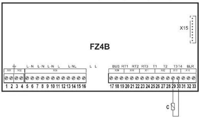
Carry out the "boiler" B connection, connecting the relay card (output with voltage-free contact) code SK16504.
Carry out the "sensor" C connection.
B - Connect to boiler on/off room Thermostat (72)
C - Generator delivery sensor
One direct zone
Schematic diagram
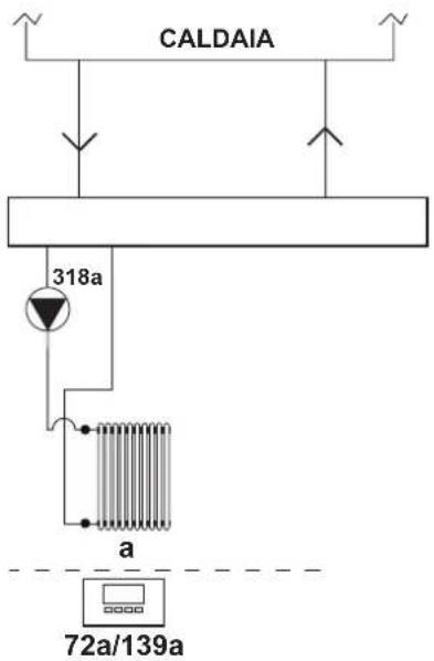
fi g. 6
Electrical connections
After installation, carry out the necessary electrical connections as shown in the wiring diagram.
Then configure the controller as described in the specific section.
| RY1 RY2 RY3 RY4 RY5 RY6 RY7 | RT1 RT2 RT3 T1 T2 T3 T4 | |||||||||||||
| 7 (L) | 8 (N) | 9 (L) | 10 (N) | 11 (L) | 12 (L) | 13 (L) | 14 (N) | 15 (L) | 16 (L) | 19 - 20 | 21 - 22 | 23 - 24 | 25 - 26 | 27 - 28 |
| 318a | 318a | 72a/139a | ||||||||||||
| 318a | 318a | 72a/139a | ||||||||||||
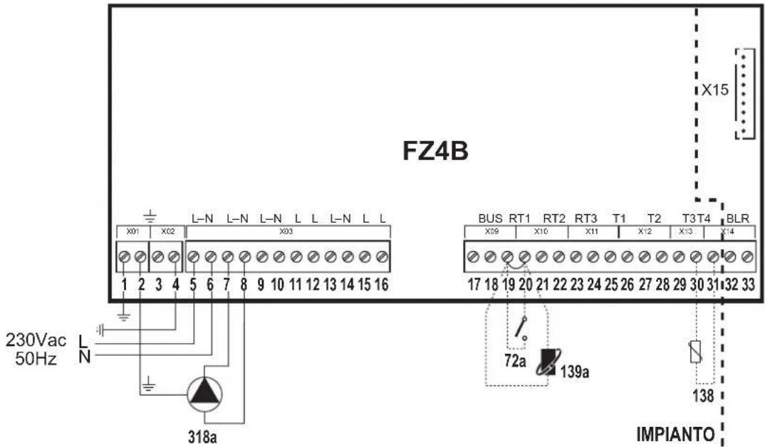
fi g. 7
Key
72a 1st zone (direct) room thermostat
138 External probe
139a 1st zone (direct) Remote Timer Control
318a 1st zone (direct) circulating pump
a 1st zone (direct)
— Necessary wiring
---- Optional wiring
To manage the sliding temperature it is necessary to purchase the external probe accessory code 013018X0
Two direct zones
Schematic diagram
![graph TD A["CALDAIA"] --> B["318a"] A --> C["318b"] B --> D["a"] C --> E["b"] D --> F["72a/139a"] E --> G["72b/139b"]](/content/2026/03/549582/images/6bd0982202f299efb1875001ccc4ddb62133a98f06865572839aa478795fb486.jpg)
fi g. 8
Electrical connections
After installation, carry out the necessary electrical connections as shown in the wiring diagram.
Then configure the controller as described in the specific section.
| RY1 RY2 RY3 RY4 RY5 RY6 RY7 | RT1 RT2 | RT3 T1 T2 | T3 T4 | |||||||||||||
| 7 (L) | 8 (N) | 9 (L) | 10 (N) | 11 (L) | 12 (L) | 13 (L) | 14 (N) | 15 (L) | 16 (L) | 19 - 20 | 21 - 22 | 23 - 24 | 25 - 26 | 27 - 28 | 29 - 30 | 30 - 31 |
| 318a | 318a | 318b | 318b | 72a/139a | 72b/139b | |||||||||||
| 318a | 318a | 318b | 318b | 72a/139a | 72b/139b | 138 | ||||||||||
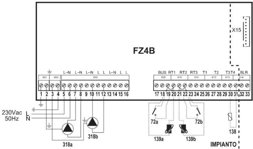
fi g. 9
Key
72a 1st zone (direct) room thermostat
72b 2nd zone (direct) room thermostat
138 External probe
139a 1st zone (direct) Remote Timer Control
139b 2nd zone (direct) Remote Timer Control
318a 1st zone (direct) circulating pump
318b 2nd zone (direct) circulating pump
a 1st zone (direct)
b 2nd zone (direct)
— Necessary wiring
---- Optional wiring
To manage the sliding temperature it is necessary to purchase the external probe accessory code 013018X0
Three direct zones
Schematic diagram
![graph TD A["CALDAIA"] --> B["318a"] A --> C["318b"] A --> D["318c"] B --> E["a"] C --> F["b"] D --> G["c"] E --> H["72a/139a"] F --> I["72b/139b"] G --> J["72c/139c"]](/content/2026/03/549582/images/3de5d0bf26be1a2374cddf2c6bb02374fb5185cf8efd7d2708edba1bd50694a6.jpg)
fig. 10
Electrical connections
After installation, carry out the necessary electrical connections as shown in the wiring diagram.
Then configure the controller as described in the specific section.
| RY1 RY2 RY3 RY4 RY5 RY6 RY7 | RT1 RT2 | RT3 T1 T2 | T3 T4 | |||||||||||||
| 7 (L) | 8 (N) | 9 (L) | 10 (N) | 11 (L) | 12 (L) | 13 (L) | 14 (N) | 15 (L) | 16 (L) | 19 - 20 | 21 - 22 | 23 - 24 | 25 - 26 | 27 - 28 | 29 - 30 | 30 - 31 |
| 318a | 318a | 318b | 318b | 318c | 318c | 72a/139a | 72b/139b | 72c/139c | ||||||||
| 318a | 318a | 318b | 318b | 318c | 318c | 72a/139a | 72b/139b | 72c/139c | 138 | |||||||
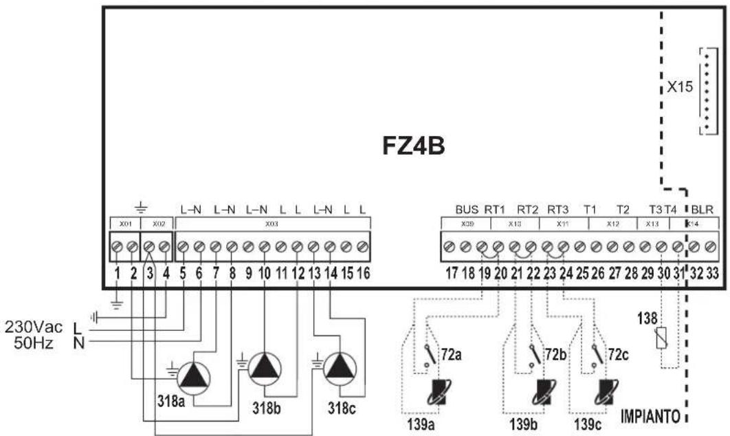
fig. 11
Key
72a 1st zone (direct) room thermostat
72b 2nd zone (direct) room thermostat
72c 3rd zone (direct) room thermostat
138 External probe
139a 1st zone (direct) Remote Timer Control
139b 2nd zone (direct) Remote Timer Control
139c 3rd zone (direct) Remote Timer Control
318a 1st zone (direct) circulating pump
318b 2nd zone (direct) circulating pump
318c 3rd zone (direct) circulating pump
a 1st zone (direct)
b 2nd zone (direct)
c 3rd zone (direct)
— Necessary wiring
---- Optional wiring
To manage the sliding temperature it is necessary to purchase the external probe accessory code 013018X0
One mixed zone
Schematic diagram
Use 3-wire mixing valves:
- OPENING PHASE 230V
- CLOSING PHASE 230V
- NEUTRAL.
with switching times (from all closed to all open) of not more than 180 seconds.
![graph TD A["CALDAIA"] --> B["315a"] B --> C["M"] C --> D["317a"] C --> E["319a"] C --> F["318a"] F --> G["a"] G --> H["72a/139a"]](/content/2026/03/549582/images/b9b893be1e6186fde6b95d56321ccddf279c41620edb6c6cbfa57d8ad6884fdf.jpg)
fi g. 12
Electrical connections
After installation, carry out the necessary electrical connections as shown in the wiring diagram.
Then configure the controller as described in the specific section.
| RY1 RY2 RY3 RY4 RY5 RY6 RY7 | RT1 RT2 RT3 T1 T2 T3 T4 | |||||||||||||||
| 7 (L) | 8 (N) | 9 (L) | 10 (N) | 11 (L) | 12 (L) | 13 (L) | 14 (N) | 15 (L) | 16 (L) | 19 - 20 | 21 - 22 | 23 - 24 | 25 - 26 | 27 - 28 | 29 - 30 | 30 - 31 |
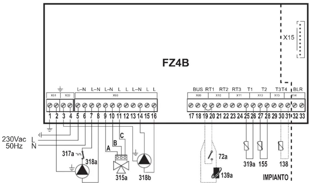
| 318a | 318a | 315a - A | 315a - B | 315a - C | 72a/139a | 319a | ||||||||||
| 318a | 318a | 315a - A | 315a - B | 315a - C | 72a/139a | 319a | 138 | |||||||||
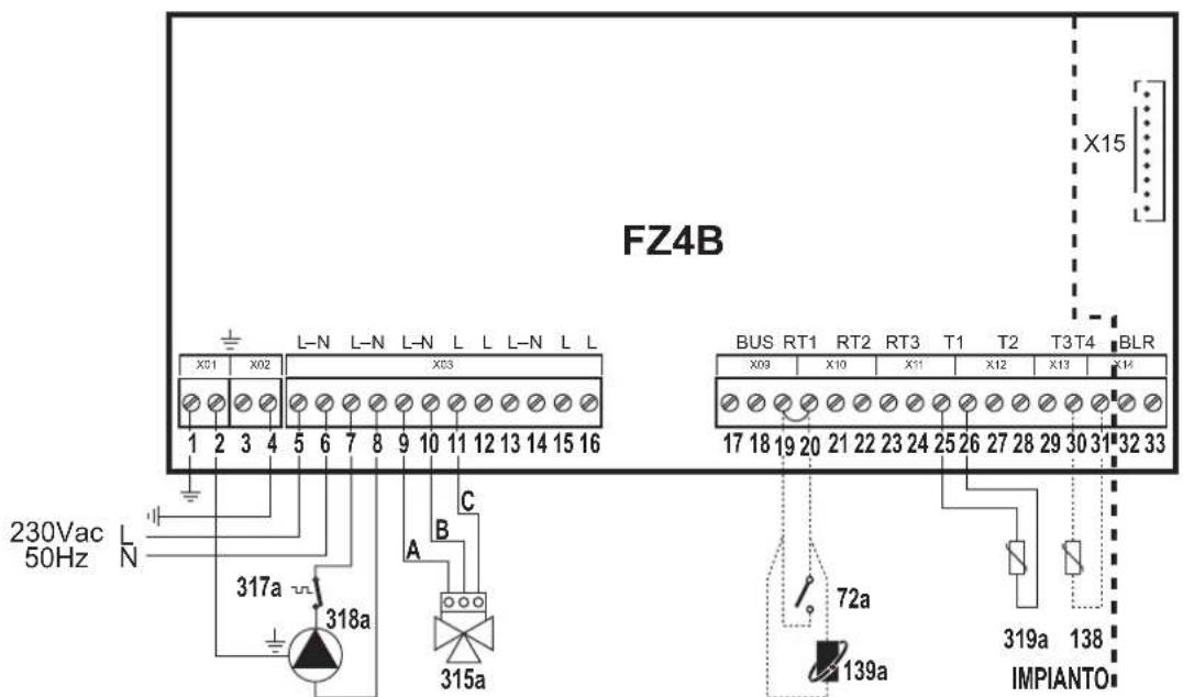
fi g. 13
Key
72a 1st zone (mixed) room thermostat
138 External probe
139a 1st zone (mixed) Remote Timer Control
315a 1st zone (mixed) mixing valve
A = OPENING PHASE
B = NEUTRAL
C = CLOSING PHASE
317a 1st zone (mixed) safety thermostat
318a 1st zone (mixed) circulating pump
319a 1st zone (mixed) delivery sensor
a 1st zone (mixed)
— Necessary wiring
---- Optional wiring
To manage the sliding temperature it is necessary to purchase the external probe accessory code 013018X0
Two mixed zones
Schematic diagram
Use 3-wire mixing valves:
- OPENING PHASE 230V
- CLOSING PHASE 230V
- NEUTRAL.
with switching times (from all closed to all open) of not more than 180 seconds.
![graph TD CALDAIA[" CALDAIA "] --> M1[" M "] CALDAIA --> M2[" M "] CALDAIA --> M3[" M "] CALDAIA --> M4[" M "] M1 --> 315a[" 315a "] M2 --> 315b[" 315b "] M3 --> 317a[" 317a "] M3 --> 317b[" 317b "] M3 --> 318a[" 318a "] M3 --> 318b[" 318b "] M4 --> 317a M4 --> 317b M4 --> 318a M4 --> 318b a --> 72a/…](/content/2026/03/549582/images/8e4174df694576bf4bec64d72487643f0de489873ed38c6d4e26b682ea7aebde.jpg)
fi g. 14
Electrical connections
After installation, carry out the necessary electrical connections as shown in the wiring diagram.
Then configure the controller as described in the specific section.
| RY1 RY2 RY3 RY4 RY5 RY6 RY7 RT1 RT2 RT3 T1 T2 T3 T4 | ||||||||||||||||
| 7 (L) | 8 (N) | 9 (L) | 10 (N) | 11 (L) | 12 (L) | 13 (L) | 14 (N) | 15 (L) | 16 (L) | 19 - 20 | 21 - 22 | 23 - 24 | 25 - 26 | 27 - 28 | 29 - 30 | 30 - 31 |
| 318a | 318a/318b | 315a - A | 315a - B | 315a - C | 318b | 315b - A | 315b - B | 315b - C | 72a/139a | 72b/139b | 319a | 319b | ||||
| 318a | 318a/318b | 315a - A | 315a - B | 315a - C | 318b | 315b - A | 315b - B | 315b - C | 72a/139a | 72b/139b | 319a | 319b | 138 | |||

72a 1st zone (mixed) room thermostat
72b 2nd zone (mixed) room thermostat
138 External probe
139a 1st zone (mixed) Remote Timer Control
139b 2nd zone (mixed) Remote Timer Control
315a 1st zone (mixed) mixing valve
A = OPENING PHASE
B = NEUTRAL
C = CLOSING PHASE
315b 2nd zone (mixed) mixing valve
A = OPENING PHASE
B = NEUTRAL
C = CLOSING PHASE
317a 1st zone (mixed) safety thermostat
317b 2nd zone (mixed) safety thermostat
318a 1st zone (mixed) circulating pump
318b 2nd zone (mixed) circulating pump
319a 1st zone (mixed) delivery sensor
319b 2nd zone (mixed) delivery sensor
a 1st zone (mixed)
b 2nd zone (mixed)
— Necessary wiring
---- Optional wiring
fi g. 15
| In case of Stand Alone 2 configuration it is necessary to purchase the NTC probe accessory code 1KWMA11W (2 mt.) or code 043005X0 (5 mt.) |
| To manage the sliding temperature it is necessary to purchase the external probe accessory code 013018X0 |
One mixed zone and one direct zone
Schematic diagram
Use 3-wire mixing valves:
- OPENING PHASE 230V
- CLOSING PHASE 230V
- NEUTRAL.
with switching times (from all closed to all open) of not more than 180 seconds.
![graph TD A["CALDAIA"] --> B["315a"] A --> C["318a"] A --> D["318b"] B --> E["M"] C --> F["317a"] C --> G["319a"] D --> H["318b"] E --> I["a"] F --> J["b"] style A fill:#f9f,stroke:#333 style B fill:#ccf,stroke:#333 style C fill:#ccf,stroke:#333 style D fill:#ccf,stroke:#333 style E fill:#dfd,stroke:…](/content/2026/03/549582/images/a379f10d1f1c426a170eacdaf5f52b9aacb47dbb7f9a552054cab661b520f14c.jpg)
fi g. 16
Electrical connections
After installation, carry out the necessary electrical connections as shown in the wiring diagram.
Then configure the controller as described in the specific section.
| RY1 RY2 RY3 RY4 RY5 RY6 RY7 | RT1 RT2 | RT3 T1 T2 | T3 T4 | |||||||||||||
| 7 (L) | 8 (N) | 9 (L) | 10 (N) | 11 (L) | 12 (L) | 13 (L) | 14 (N) | 15 (L) | 16 (L) | 19 - 20 | 21 - 22 | 23 - 24 | 25 - 26 | 27 - 28 | 29 - 30 | 30 - 31 |
| 318a | 318a | 315a - A | 315a - B | 315a - C | 318b | 318b | 72a/139a | 72b/139b | 319a | |||||||
| 318a | 318a | 315a - A | 315a - B | 315a - C | 318b | 318b | 72a/139a | 72b/139b | 319a | 138 | ||||||
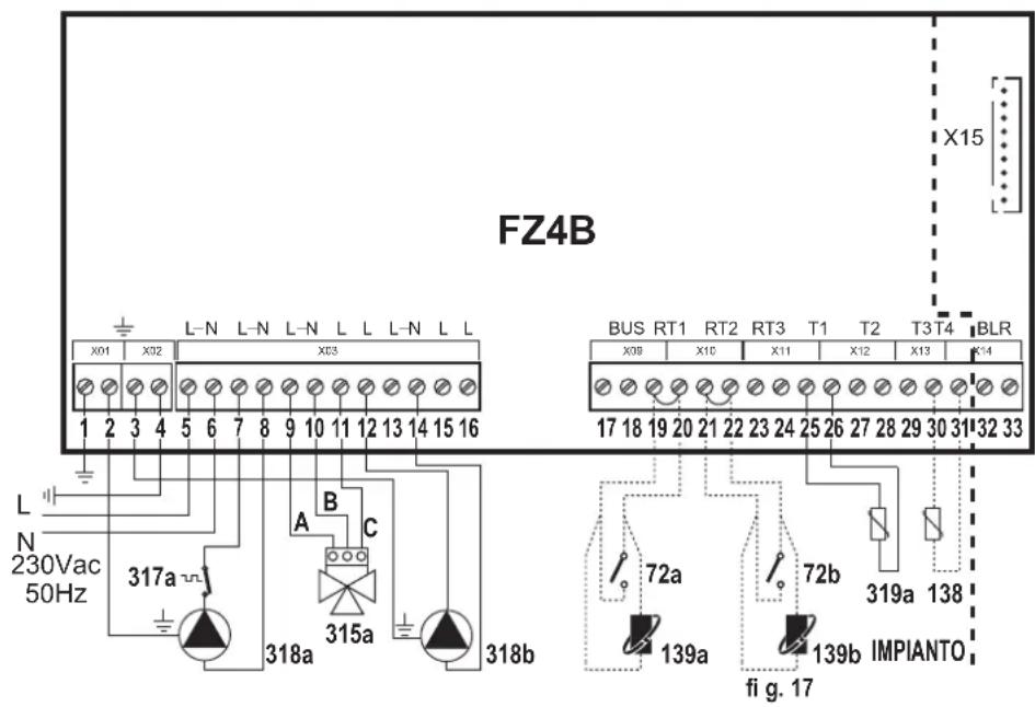
To manage the sliding temperature it is necessary to purchase the external probe accessory code 013018X0
72a 1st zone (mixed) room thermostat
72b 2nd zone (direct) room thermostat
138 External probe
139a 1st zone (mixed) Remote Timer Control
139b 2nd zone (direct) Remote Timer Control
315a 1st zone (mixed) mixing valve
A = OPENING PHASE
B = NEUTRAL
C = CLOSING PHASE
317a 1st zone (mixed) safety thermostat
318a 1st zone (mixed) circulating pump
318b 2nd zone (direct) circulating pump
319a 1st zone (mixed) delivery sensor
a 1st zone (mixed)
b 2nd zone (direct)
— Necessary wiring
---- Optional wiring
One mixed zone and two direct zones
Schematic diagram
Use 3-wire mixing valves:
- OPENING PHASE 230V
- CLOSING PHASE 230V
- NEUTRAL.
with switching times (from all closed to all open) of not more than 180 seconds.
![graph TD A["CALDAIA"] --> B["315a"] B --> C["M"] C --> D["317a"] C --> E["319a"] D --> F["318a"] E --> G["318a"] F --> H["a"] G --> I["b"] H --> J["c"] I --> K["72a/139a"] I --> L["72b/139b"] I --> M["72c/139c"]](/content/2026/03/549582/images/129f4e650c0266e2bf68ec6a4fa5402770d05c241060a0fa25e7af0cfe1dfa7d.jpg)
fi g. 18
Electrical connections
After installation, carry out the necessary electrical connections as shown in the wiring diagram.
Then configure the controller as described in the specific section.
| RY1 RY2 | RY3 RY4 RY5 RY6 RY7 RT1 RT2 RT3 T1 T2 T3 T4 | |||||||||||||||
| 7 (L) | 8 (N) | 9 (L) | 10 (N) | 11 (L) | 12 (L) | 13 (L) | 14 (N) | 15 (L) | 16 (L) | 19 - 20 | 21 - 22 | 23 - 24 | 25 - 26 | 27 - 28 | 29 - 30 | 30 - 31 |
| 318a | 318a | 315a - A | 315a - B | 315a - C | 318b | 318c | 318b/318c | 72a/139a | 72b/139b | 72c/139c | 319a | |||||
| 318a | 318a | 315a - A | 315a - B | 315a - C | 318b | 318c | 318b/318c | 72a/139a | 72b/139b | 72c/139c | 319a | 138 | ||||
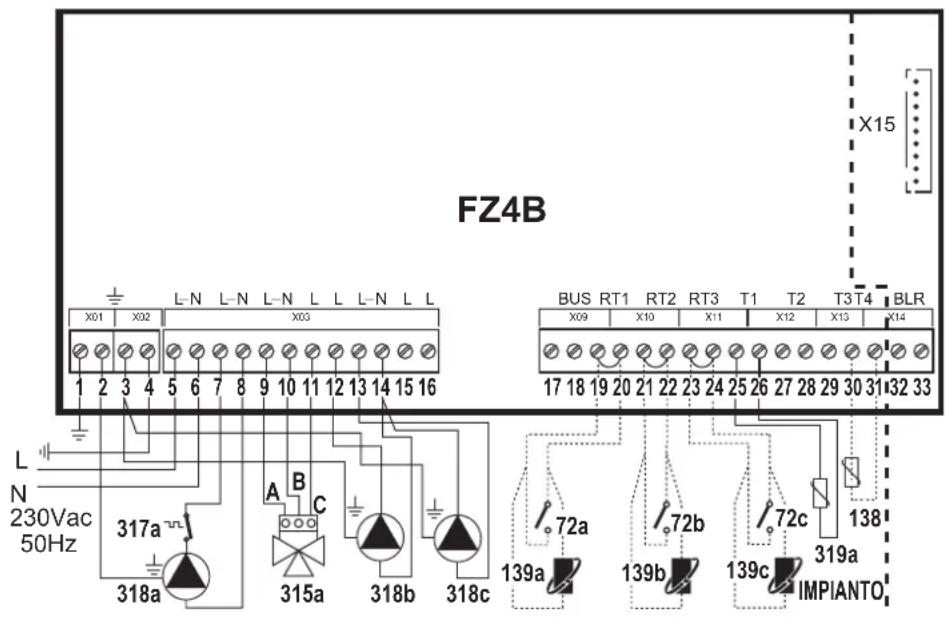
fi g. 19
72a 1st zone (mixed) room thermostat
72b 2nd zone (direct) room thermostat
72c 3rd zone (direct) room thermostat
138 External probe
139a 1st zone (mixed) Remote Timer Control
139b 2nd zone (direct) Remote Timer Control
139c 3rd zone (direct) Remote Timer Control
315a 1st zone (mixed) mixing valve
A = OPENING PHASE
B = NEUTRAL
C = CLOSING PHASE
317a 1st zone (mixed) safety thermostat
318a 1st zone (mixed) circulating pump
318b 2nd zone (direct) circulating pump
318c 3rd zone (direct) circulating pump
319a 1st zone (mixed) delivery sensor
a 1st zone (mixed)
b 2nd zone (direct)
c 3rd zone (direct)
— Necessary wiring
---- Optional wiring
To manage the sliding temperature it is necessary to purchase the external probe accessory code 013018X0
Two mixed zones and tone direct zone
Schematic diagram
Use 3-wire mixing valves:
- OPENING PHASE 230V
- CLOSING PHASE 230V
- NEUTRAL.
with switching times (from all closed to all open) of not more than 180 seconds.
![graph TD A["CALDAIA"] --> B["M"] A --> C["M"] A --> D["M"] B --> E["315a"] B --> F["317a"] B --> G["319a"] C --> H["315b"] C --> I["317b"] C --> J["319b"] D --> K["318c"] D --> L["318a"] D --> M["318b"] M --> N["a"] M --> O["b"] M --> P["c"] N --> Q["72a/139a"] O --> R["72b/139b"] P --> S["72c/139c"…](/content/2026/03/549582/images/909d710a769f270edaeb7f670d3d2d55dc1f4b6284fdb07cc2c5dacdec0d8dea.jpg)
fi g. 20
Electrical connections
After installation, carry out the necessary electrical connections as shown in the wiring diagram.
Then configure the controller as described in the specific section.
| RY1 RY2 RY3 RY4 RY5 RY6 RY7 RT1 RT2 RT3 T1 T2 T3 T4 | ||||||||||||||||
| 7 (L) | 8 (N) | 9 (L) | 10 (N) | 11 (L) | 12 (L) | 13 (L) | 14 (N) | 15 (L) | 16 (L) | 19 - 20 | 21 - 22 | 23 - 24 | 25 - 26 | 27 - 28 | 29 - 30 | 30 - 31 |
| 318a | 318a/318b | 315a - A | 315a - B | 315a - C | 318b | 315b - A | 315b - B/318c | 315b - C | 318c | 72a/139a | 72b/139b | 72c/139c | 319a | 319b | ||
| 318a | 318a/318b | 315a - A | 315a - B | 315a - C | 318b | 315b - A | 315b - B/318c | 315b - C | 318c | 72a/139a | 72b/139b | 72c/138c | 319a | 319b | 138 | |
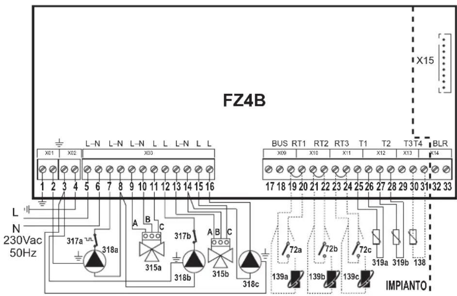
fi g. 21
72a 1st zone (mixed) room thermostat
72b 2nd zone (mixed) room thermostat
72c 3rd zone (direct) room thermostat
138 External probe
139a 1st zone (mixed) Remote Timer Control
139b 2nd zone (mixed) Remote Timer Control
139c 3rd zone (direct) Remote Timer Control
315a 1st zone (mixed) mixing valve
A = OPENING PHASE
B = NEUTRAL
C = CLOSING PHASE
315b 2nd zone (mixed) mixing valve
A = OPENING PHASE
B = NEUTRAL
C = CLOSING PHASE
317a 1st zone (mixed) safety thermostat
317b 2nd zone (mixed) safety thermostat
318a 1st zone (mixed) circulating pump
318b 2nd zone (mixed) circulating pump
318c 3rd zone (direct) circulating pump
319a 1st zone (mixed) delivery sensor
319b 2nd zone (mixed) delivery sensor
a 1st zone (mixed)
b 2nd zone (mixed)
c 3rd zone (direct)
— Necessary wiring
---- Optional wiring
In case of Stand Alone 2 configuration it is necessary to purchase the NTC probe accessory code 1KWMA11W (2 mt.) or code 043005X0 (5 mt.)
To manage the sliding temperature it is necessary to purchase the external probe accessory code 013018X0
One hot water tank circuit
Schematic diagram

fi g. 22
Electrical connections
After installation, carry out the necessary electrical connections as shown in the wiring diagram.
Then configure the controller as described in the specific section.
| RY1 RY2 RY3 RY4 RY5 RY6 RY7 | RT1 RT2 RT3 T1 T2 T3 T4 | |||||||||||||||
| 7 (L) | 8 (N) | 9 (L) | 10 (N) | 11 (L) | 12 (L) | 13 (L) | 14 (N) | 15 (L) | 16 (L) | 19 - 20 | 21 - 22 | 23 - 24 | 25 - 26 | 27 - 28 | 29 - 30 | 30 - 31 |
| 318a | 318a | 155 | ||||||||||||||
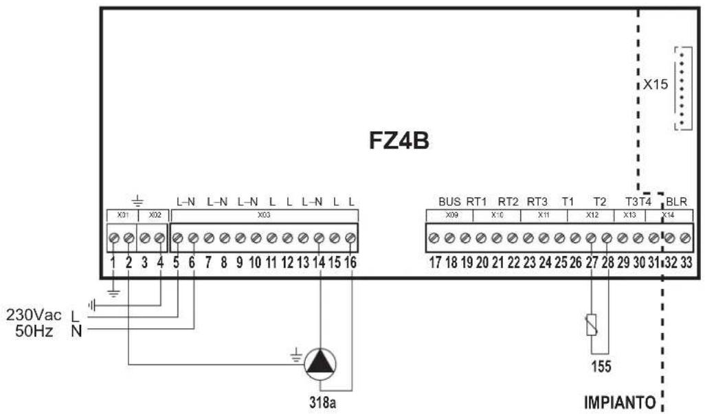
fi g. 23
Key
318a Hot water tank circulating pump
155 Hot water tank probe
a Hot water tank circuit
— Necessary wiring
---- Optional wiring
If a hot water tank thermostat (not supplied) is used, it is necessary to purchase the accessory kit code 013017X0 (to be connected in place of the Hot water tank Probe)
One direct zone and one hot water tank circuit
Schematic diagram
![graph TD A["CALDAIA"] --> B["318a"] A --> C["318b"] B --> D["a"] C --> D D --> E["72a/139a"] F["155"] --> G["b"] G --> H["Output"] style A fill:#f9f,stroke:#333 style F fill:#ccf,stroke:#333](/content/2026/03/549582/images/9de53ae96976239132f2d1443fe9d1cf1fc4be9d1a89057828ad101a88b6e9c0.jpg)
• Management of priority/contemporaneity with parameter FZ4B P25
• Management of Economy/Comfort only with Remote Timer Control
fi g. 24
Electrical connections
After installation, carry out the necessary electrical connections as shown in the wiring diagram.
Then configure the controller as described in the specific section.
| RY1 RY2 RY3 RY4 RY5 RY6 RY7 | RT1 RT2 RT3 T1 T2 T3 T4 | |||||||||||||||
| 7 (L) | 8 (N) | 9 (L) | 10 (N) | 11 (L) | 12 (L) | 13 (L) | 14 (N) | 15 (L) | 16 (L) | 19 - 20 | 21 - 22 | 23 - 24 | 25 - 26 | 27 - 28 | 29 - 30 | 30 - 31 |
| 318a | 318a | 318b | 318b | 72a/139a | 155 | |||||||||||
| 318a | 318a | 318b | 318b | 72a/139a | 155 | 138 | ||||||||||
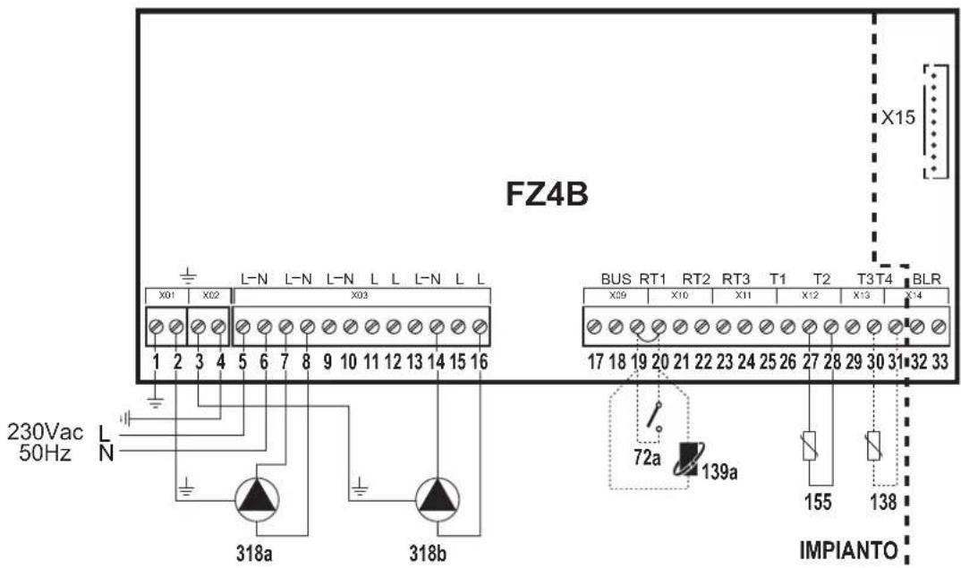
fig. 25
Key
72a 1st zone (direct) room thermostat
138 External probe
139a 1st zone (direct) Remote Timer Control
318a 1st zone (direct) circulating pump
318b Hot water tank circulating pump
155 Hot water tank probe
a 1st zone (direct)
b Hot water tank circuit
— Necessary wiring
---- Optional wiring
| To manage the sliding temperature it is necessary to purchase the external probe accessory code 013018X0 |
| If a hot water tank thermostat (not supplied) is used, it is necessary to purchase the accessory kit code 013017X0 (to be connected in place of the Hot water tank Probe) |
Two direct zones and one hot water tank circuit
Schematic diagram
![graph TD A["318a"] --> B["a"] C["318b"] --> D["b"] E["318c"] --> F["c"] B --> G["72a/139a"] D --> H["72b/139b"] G --> I["Valve 155"] H --> J["Valve 155"] I --> K["Outlet"] J --> L["Outlet"]](/content/2026/03/549582/images/87f13b872c79f3b3de226ed7a699ea5357235e48612ea02ed98ecff20e5f94f8.jpg)
- Management of priority/contemporaneity with parameter FZ4B P25
- Management of Economy/Comfort only with Remote Timer Control
fi g. 26
Electrical connections
After installation, carry out the necessary electrical connections as shown in the wiring diagram.
Then configure the controller as described in the specific section.
| RY1 RY2 RY3 RY4 RY5 RY6 RY7 | RT1 RT2 RT3 T1 T2 T3 T4 | |||||||||||||||
| 7 (L) | 8 (N) | 9 (L) | 10 (N) | 11 (L) | 12 (L) | 13 (L) | 14 (N) | 15 (L) | 16 (L) | 19 - 20 | 21 - 22 | 23 - 24 | 25 - 26 | 27 - 28 | 29 - 30 | 30 - 31 |
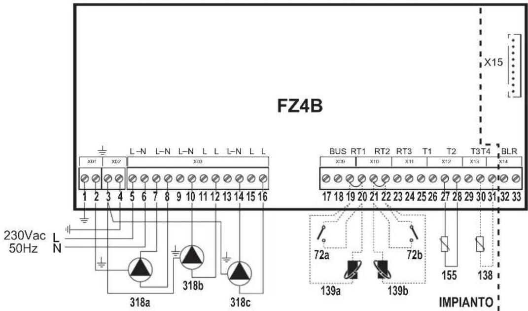
| 318a | 318a | 318b | 318b | 318c | 318c | 72a/139a | 72b/139b | 155 | ||||||||
| 318a | 318a | 318b | 318b | 318c | 318c | 72a/139a | 72b/139b | 155 | 138 | |||||||
fi g. 27
Key
72a 1st zone (direct) room thermostat
72b 2nd zone (direct) room thermostat
138 External probe
139a 1st zone (direct) Remote Timer Control
139b 2nd zone (direct) Remote Timer Control
155 Hot water tank probe
318a 1st zone (direct) circulating pump
318b 2nd zone (direct) circulating pump
318c Hot water tank circulating pump
a 1st zone (direct)
b 2nd zone (direct)
c Hot water tank circuit
— Necessary wiring
---- Optional wiring
To manage the sliding temperature it is necessary to purchase the external probe accessory code 013018X0
If a hot water tank thermostat (not supplied) is used, it is necessary to purchase the accessory kit code 013017X0 (to be connected in place of the Hot water tank Probe)
Three direct zones and one hot water tank circuit
Schematic diagram
![graph TD A["318a"] --> B["a"] C["318b"] --> D["b"] E["318c"] --> F["c"] G["318d"] --> H["d"] I["72a/139a"] --> J["72b/139b"] K["72c/139c"] --> L["72d/139c"] M["155"] --> N["Vertical vessel"] style A fill:#f9f,stroke:#333 style C fill:#f9f,stroke:#333 style E fill:#f9f,stroke:#333 style G fill:#f9f,s…](/content/2026/03/549582/images/5e000b41e9ea3dd737dba3dd9ef31eb14d84896255c0c0eb78bb0b56180387c9.jpg)
• Management of priority/contemporaneity with parameter FZ4B P25
• Management of Economy/Comfort only with Remote Timer Control
fi g. 28
Electrical connections
After installation, carry out the necessary electrical connections as shown in the wiring diagram.
Then configure the controller as described in the specific section.
| RY1 RY2 RY3 | RY4 RY5 RY6 RY7 | RT1 RT2 | RT3 T1 T2 | T3 T4 | ||||||||||||
| 7 (L) | 8 (N) | 9 (L) | 10 (N) | 11 (L) | 12 (L) | 13 (L) | 14 (N) | 15 (L) | 16 (L) | 19 - 20 | 21 - 22 | 23 - 24 | 25 - 26 | 27 - 28 | 29 - 30 | 30 - 31 |
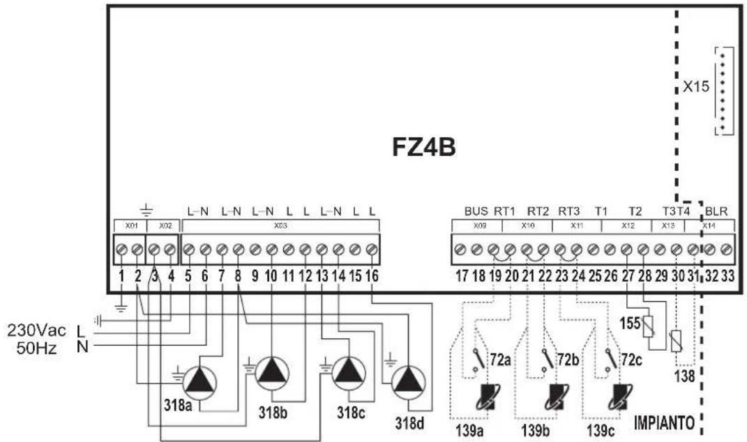
| 318a | 318a/318d | 318b | 318b | 318c | 318c | 318d | 72a/139a | 72b/139b | 72c/139c | 155 | ||||||
| 318a | 318a/318d | 318b | 318b | 318c | 318c | 318d | 72a/139a | 72b/139b | 72c/139c | 155 | 138 | |||||
fi g. 29
Key
72a 1st zone (direct) room thermostat
72b 2nd zone (direct) room thermostat
72c 3rd zone (direct) room thermostat
138 External probe
139a 1st zone (direct) Remote Timer Control
139b 2nd zone (direct) Remote Timer Control
139c 3rd zone (direct) Remote Timer Control
155 Hot water tank probe
318a 1st zone (direct) circulating pump
318b 2nd zone (direct) circulating pump
318c 3rd zone (direct) circulating pump
318d Hot water tank circulating pump
a 1st zone (direct)
b 2nd zone (direct)
c 3rd zone (direct)
d Hot water tank circuit
—Necessary wiring
---- Optional wiring
To manage the sliding temperature it is necessary to purchase the external probe accessory code 013018X0
If a hot water tank thermostat (not supplied) is used, it is necessary to purchase the accessory kit code 013017X0 (to be connected in place of the Hot water tank Probe)
One mixed zone and one hot water tank circuit
Schematic diagram
Use 3-wire mixing valves:
- OPENING PHASE 230V
- CLOSING PHASE 230V
- NEUTRAL.
with switching times (from all closed to all open) of not more than 180 seconds.
• Management of priority/contemporaneity with parameter FZ4B P25
- Management of Economy/Comfort only with Remote Timer Control
![graph TD A["315a"] --> B["317a"] B --> C["319a"] C --> D["318a"] D --> E["318b"] E --> F["155"] F --> G["b"] G --> H["72a/139a"] I["a"] --> J["Control Unit"] style A fill:#f9f,stroke:#333 style G fill:#ccf,stroke:#333](/content/2026/03/549582/images/b2844124f9e3bea7b69abed7681ecec84b8ef269224a0196eaec9bb173d59835.jpg)
fi g. 30
Electrical connections
After installation, carry out the necessary electrical connections as shown in the wiring diagram.
Then configure the controller as described in the specific section.
| RY1 RY2 RY3 RY4 RY5 RY6 RY7 | RT1 RT2 RT3 T1 T2 T3 T4 | |||||||||||||||
| 7 (L) | 8 (N) | 9 (L) | 10 (N) | 11 (L) | 12 (L) | 13 (L) | 14 (N) | 15 (L) | 16 (L) | 19 - 20 | 21 - 22 | 23 - 24 | 25 - 26 | 27 - 28 | 29 - 30 | 30 - 31 |
| 318a | 318a | 315a - A | 315a - B | 315a - C | 318b | 318b | 72a/139a | 319a | 155 | |||||||
| 318a | 318a | 315a - A | 315a - B | 315a - C | 318b | 318b | 72a/139a | 319a | 155 | 138 | ||||||
fi g. 31
Key
72a 1st zone (mixed) room thermostat
138 External probe
139a 1st zone (mixed) Remote Timer Control
315a 1st zone (mixed) mixing valve
A = OPENING PHASE
B = NEUTRAL
C = CLOSING PHASE
155 Hot water tank probe
317a 1st zone (mixed) safety thermostat
318a 1st zone (mixed) circulating pump
318b Hot water tank circulating pump
319a 1st zone (mixed) delivery sensor
a 1st zone (mixed)
b Hot water tank circuit
— Necessary wiring
- - - - Optional wiring
| In case of Stand Alone 2 configuration it is necessary to purchase the NTC probe accessory code 1KWMA11W (2 mt.) or code 043005X0 (5 mt.) |
| To manage the sliding temperature it is necessary to purchase the external probe accessory code 013018X0 |
| If a hot water tank thermostat (not supplied) is used, it is necessary to purchase the accessory kit code 013017X0 (to be connected in place of the Hot water tank Probe) |
One mixed zone, one direct zone and one hot water tank circuit
Schematic diagram
Use 3-wire mixing valves:
- OPENING PHASE 230V
- CLOSING PHASE 230V
- NEUTRAL.
with switching times (from all closed to all open) of not more than 180 seconds.
• Management of priority/contemporaneity with parameter FZ4B P25
• Management of Economy/Comfort only with Remote Timer Control
![graph TD A["CALDAIA"] --> B["Valve 315a"] A --> C["Valve 317a"] A --> D["Valve 319a"] A --> E["Valve 318a"] B --> F["Sensor a"] C --> G["Sensor b"] D --> H["Sensor c"] E --> I["Reactor"] I --> J["Reactor 72a/139a"] I --> K["Reactor 72b/139b"] J --> L["Reactor 155"] K --> L L --> M["Reactor C"]](/content/2026/03/549582/images/9d81fa3171a9b8432f0ecb9d4d0c40187871c2ad8d4bb1005bfb50efbeba6633.jpg)
fi g. 32
Electrical connections
After installation, carry out the necessary electrical connections as shown in the wiring diagram.
Then configure the controller as described in the specific section.
| RY1 RY2 RY3 RY4 RY5 RY6 RY7 RT1 RT2 RT3 T1 T2 T3 T4 | ||||||||||||||||
| 7 (L) | 8 (N) | 9 (L) | 10 (N) | 11 (L) | 12 (L) | 13 (L) | 14 (N) | 15 (L) | 16 (L) | 19 - 20 | 21 - 22 | 23 - 24 | 25 - 26 | 27 - 28 | 29 - 30 | 30 - 31 |
| 318a | 318a | 315a - A | 315a - B | 315a - C | 318b | 318b/318c | 318c | 72a/139a | 72b/139b | 319a | 155 | |||||
| 318a | 318a | 315a - A | 315a - B | 315a - C | 318b | 318b/318c | 318c | 72a/139a | 72b/139b | 319a | 155 | 138 | ||||
72a 1st zone (mixed) room thermostat
72b 2nd zone (direct) room thermostat
138 External probe
139a 1st zone (mixed) Remote Timer Control
139b 2nd zone (direct) Remote Timer Control
315a 1st zone (mixed) mixing valve
A = OPENING PHASE
B = NEUTRAL
C = CLOSING PHASE
155 Hot water tank probe
317a 1st zone (mixed) safety thermostat
318a 1st zone (mixed) circulating pump
318b 2nd zone (direct) circulating pump
318c Hot water tank circulating pump
319a 1st zone (mixed) delivery sensor
a 1st zone (mixed)
b 2nd zone (direct)
c Hot water tank circuit
— Necessary wiring
---- Optional wiring
| In case of Stand Alone 2 configuration it is necessary to purchase the NTC probe accessory code 1KWMA11W (2 mt.) or code 043005X0 (5 mt.) |
| To manage the sliding temperature it is necessary to purchase the external probe accessory code 013018X0 |
| If a hot water tank thermostat (not supplied) is used, it is necessary to purchase the accessory kit code 013017X0 (to be connected in place of the Hot water tank Probe) |
3. FIRST STARTUP (AUTOCONFIGURATION)
After carrying out the connection operations, switch on the power to the boiler; set the heating and DHW set points to the required max. value and switch on the zone controller only afterwards.
If present, activate the request status of possible Room Chronothermostats (closed contact) connected to the zone controller.
Press the AUTOCONFIG button or Autoconfiguration (detail 5 - Fig. 34) on the controller and keep it pressed until all the bottom LEDs blink as follows:
![graph TD A["04"] --> B["DISP1"] B --> C["U01"] B --> D["LY"] E["SW01"] --> F["STATO"] G["SW02"] --> F H["SW03"] --> I["SW04"] J["Hand icon"] --> K["5"]](/content/2026/03/549582/images/ba755313f19e0b577351b896a39eb41dd65ff80f23f4978d83e554a77173e31c.jpg)
fi g. 34 - AUTOCONFIGURATION activation
fi g. 35 - Saving of system confi guration
When all the bottom LEDs and the STATUS LED blink, release the AUTOCONFIG button or Autoconfiguration (detail 5 - Fig. 34). When the Status LED stops blinking, make sure the bottoms LEDs that are on fixed match the required system configuration table (fig. 35).
If this does not occur, check the wiring again and repeat the system AutoConfiguration procedure.
If one or more Remote Timer Controls are used, at the end of the Autoconfiguration procedure the Heating and DHW setpoints must be set (see the relevant documentation).
4. OPERATION
The board FZ4B is a zone controller that can be configured in several ways.
There are six main configurations:
1. "Stand Alone 1" confi igurations without DHW
This means that the board FZ4B works alone, without the OpenTherm connection to the boiler.
To request heat, it will use the relay of card SK connected to connector X15.
Connecting one or more Remote Controls: the functions associated with the DHW settings will be ignored (the DHW setpoint must be 0° C and the DHW sensor “- -”); the board FZ4B must send the heating bits to activate the remote control icons. The min. and max. Setpoint limits are provided by board FZ4B.
2. "Stand Alone 1" confi igurations with DHW (On system)
This means that the board FZ4B works alone, without the OpenTherm connection to the boiler.
To request heat, it will use the relay of card SK connected to connector X15; to know the temperature of the hot water tank, hydraulically connected in parallel to heating zones, it will use input T2.
Connecting one or more Remote Controls: the functions associated with the DHW settings will be managed in parallel; the board FZ4B must send the heating and DHW bits to activate the remote control icons. The min. and max. Setpoint limits are provided by board FZ4B. The DHW information will be T2. The economy/comfort function of each remote control will act on the DHW mode of the board FZ4B.
3. "Stand Alone 2" confi igurations without DHW
This means that the board FZ4B works alone, without the OpenTherm connection to the boiler.
To know the delivery temperature it will use input T3; to demand heat it will use the relay of card SK connected to connector X15.
Connecting one or more Remote Controls: the functions associated with the DHW settings will be ignored (the DHW setpoint must be 0°C and the DHW sensor "- -"); the board FZ4B must send the heating bits to activate the remote control icons. The min. and max. Setpoint limits are provided by board FZ4B. The heating sensor information will be that of input T3.
4. "Stand Alone 2" confi igurations with DHW (On system)
This means that the board FZ4B works alone, without the OpenTherm connection to the boiler.
To know the delivery temperature it will use input T3; to demand heat it will use the relay of card SK connected to connector X15; to know the temperature of the hot water tank, hydraulically connected in parallel to heating zones, it will use input T2.
Connecting one or more Remote Controls: the functions associated with the DHW settings will be managed in parallel; the board FZ4B must send the heating and DHW bits to activate the remote control icons. The min. and max. Setpoint limits are provided by board FZ4B. The heating sensor information will be that of T3; whereas that of the DHW will be T2. The economy/comfort function of each remote control will act on the DHW mode of the board FZ4B.
5. "Communicating" configurations with DHW (Integrated in boiler)
This means that the board FZ4B works alone, with the OpenTherm connection to the boiler.
To know the delivery temperature, demand heat and to know the temperature of the hot water tank, connected in the boiler, it will use the OpenTherm protocol.
Connecting one or more Remote Controls: the functions associated with the DHW settings will be managed in parallel; the board FZ4B must transfer the heating, DHW and power bits to activate the remote control icons coming from the boiler board. The min. and max. heating Setpoint limits are provided by board FZ4B; those of the DHW will be supplied by the boiler board. It must send the room temperature detected by the Remote Control RT1 to the boiler board; in case of no Remote Controls, it must send the value 25°C the boiler board. The economy/comfort function of each remote control will act on the DHW mode of the boiler board.
6. "Communicating" confi gurations with DHW (On system)
This means that the board FZ4B works alone, with the OpenTherm connection to the boiler.
To know the delivery temperature and demand heat it will use the OpenTherm protocol. To know the temperature of the hot water tank, hydraulically connected in parallel to heating zones, it will use input T2.
Connecting one or more Remote Controls: the functions associated with the DHW settings will be managed in parallel; the board FZ4B must transfer the heating, DHW and power bits to activate the remote control icons coming from the boiler board. The min. and max. Setpoint limits are provided by board FZ4B. It must send the room temperature detected by the Remote Control RT1 to the boiler board; in case of no Remote Controls, it must send the value 25°C the boiler board. The economy/comfort function of each remote control will act on the DHW mode of the board FZ4B.
5. "STAND ALONE 1" CONFIGURATIONS.
5.1 "ONE DIRECT ZONE – NO EXTERNAL SENSOR"
Autoconfi guration
| Connection Description | ||
| 7 | Pump phase or Valve (RY1) Direct zone 1 | |
| 8 | Pump neutral or Valve (RY1) Direct zone 1 | |
| 19 | On/Off Thermostat or Remote Control (RT1) Direct zone 1 | |
| 20 | On/Off Thermostat or Remote Control (RT1) Direct zone 1 | |
| X15 | Card SK connected | |
5.1.1 On/Off Thermostat
Zone pump
System circulation (including boiler) is ensured by the zone circulating pump: therefore the boiler does not have to have the circulating pump.
Zone valve
System circulation (including boiler) is ensured by the boiler circulating pump: therefore the boiler must have the circulating pump.
Algorithm
a. Zone card Heating Setpoint = Zone1 Heating Setpoint
b. Zone1 Heating Setpoint = Zona1 Max.Temperature (TSP02) + Zona1 calculated setpoint Offset (TSP03).
c. If RT1 closes the contact, RY1 must be powered; and must remain powered while RT1 remains closed.
The Delay for Zone timer (TSP29) starts: during this time the relay of card SK must be unpowered.
d. At the end of the Delay for Zone timer (TSP29), the relay of card SK must be powered.
e. If RT1 opens the contact, the relay of card SK must be unpowered; whereas RY1 must remain powered for the entire duration of the Post-circulation Time timer (TSP27); at the end of this timer, RY1 must be unpowered.
5.1.2 Remote Control
Zone pump
System circulation (including boiler) is ensured by the zone circulating pump: therefore the boiler does not have to have the circulating pump.
Zone valve
System circulation (including boiler) is ensured by the boiler circulating pump: therefore the boiler must have the circulating pump.
Algorithm
a. Zone card Heating Setpoint = Zone1 Heating Setpoint
b. Zone1 Heating Setpoint = Control Setpoint calculated from Remote Control + Zone1 Calculated setpoint Offset (TSP03).
The Control Setpoint calculated from Remote Control is limited by ID57 of the Remote Control itself (Heating temperature adjustment button).
The range for management of the Remote Control ID57 is defined by the parameters: Zone1 Min. Temperature (TSP01) and Zone1 Max. Temperature (TSP02).
c. If RT1 activates the request, RY1 must be powered; and must remain powered while RT1 remains in request status.
The Delay for Zone timer (TSP29) starts: during this time the relay of card SK must be unpowered.
d. At the end of the Delay for Zone timer (TSP29), the relay of card SK must be powered.
e. If RT1 deactivates the request, the relay of card SK must be unpowered; whereas RY1 must remain powered for the entire duration of the Post-circulation Time timer (TSP27); at the end of this timer, RY1 must be unpowered.
5.2 "ONE DIRECT ZONE – WITH EXTERNAL SENSOR"
Autoconfi guration:
| Connection Description | ||
| 7 | Pump phase or Valve (RY1) Direct Zone 1 | |
| 8 | Pump neutral or Valve (RY1) Direct zone 1 | |
| 19 | On/Off Thermostat or Remote Control (RT1) Direct zone 1 | |
| 20 | On/Off Thermostat or Remote Control (RT1) Direct zone 1 | |
| 30 | NTC sensor (T4) | External probe |
| 31 | NTC sensor (T4) | External probe |
| X15 | Card SK connected | |
5.2.1 On/Off Thermostat
The algorithm remains the same as the configuration: 5.1 "ONE Direct Zone – No External Sensor".
What changes is only the calculation of Zone1 Heating Setpoint if the sliding temperature was activated.
a. If Zone 1 External Probe Curve (TSP05) is equal to 0.
Zone1 Heating Setpoint = Zone1 Max. Temperature (TSP02) + Zone1 calculated setpoint Offset (TSP03).
b. If Zone 1 External Probe Curve (TSP05) is between 1 and 10.
Zone1 Heating Setpoint = Setpoint calculated from External Probe + Zone1 calculated setpoint Offset (TSP03).
However:
If Zone1 Max. Temperature (TSP02) < Setpoint calculated from External Probe then Setpoint calculated from External Probe = Zone1 Max. Temperature (TSP02).
5.2.2 Remote Control
The algorithm remains the same as the configuration: 5.1 "ONE Direct Zone – No External Sensor".
What changes is only the calculation of Zone1 Heating Setpoint if the sliding temperature was activated.
a. If Zone 1 External Probe Curve (TSP05) is equal to 0.
Zone1 Heating Setpoint = Control Setpoint calculated from Remote Control + Zone1 calculated setpoint Offset (TSP03).
b. If Zone 1 External Probe Curve (TSP05) is between 1 and 10.
Zone1 Heating Setpoint = Setpoint calculated from External Probe + Zone1 calculated setpoint Offset (TSP03).
However:
If Zone1 Max. Temperature (TSP02) < Setpoint calculated from External Probe then Setpoint calculated from External Probe = Zone1 Max. Temperature (TSP02). If Control Setpoint calculated from Remote Control < Setpoint calculated from External Probe then Setpoint calculated from External Probe = Control Setpoint calculated from Remote Control.
5.3 "TWO DIRECT ZONES - NO EXTERNAL SENSOR"
Autoconfi guration:
| Connection Description | ||
| 7 | Pump phase or Valve (RY1) Direct zone 1 | |
| 8 | Pump neutral or Valve (RY1) Direct zone 1 | |
| 10 | Pump neutral or Valve (RY2) Direct zone 2 | |
| 12 | Pump phase or Valve (RY4) Direct zone 2 | |
| 19 | On/Off Thermostat or Remote Control (RT1) Direct zone 1 | |
| 20 | On/Off Thermostat or Remote Control (RT1) Direct zone 1 | |
| 21 | On/Off Thermostat or Remote Control (RT2) Direct zone 2 | |
| 22 | On/Off Thermostat or Remote Control (RT2) Direct zone 2 | |
| X15 | Card SK connected | |
The algorithm remains the same as the configuration: 5.1 "ONE Direct Zone – No External Sensor".
What changes is:
a. The calculation of Zone card Heating Setpoint
In case of simultaneous request, the Zone card Heating Setpoint is equal to the higher of the two: Zone1 Heating Setpoint and Zone2 Heating Setpoint.
If the zone that ends the request has the higher Heating Setpoint, the Zone card Heating Setpoint must be immediately decreased until it is equal to the Heating Setpoint of the zone still in request status.
If the zone that starts the request has a higher Heating Setpoint than the zone already in request status, the Zone card Heating Setpoint must be immediately increased until it is equal to the higher Heating Setpoint of the zone in request status.
b. Each zone has its own adjustment parameters.
c. Post-circulation time
This must be carried out only on the last zone that ends the request.
Also, if the last zone in request status is doing post-circulation and another zone starts its own request, post-circulation must be stopped: so that there is always and only a single zone in post-circulation.
5.4 "TWO DIRECT ZONES – WITH EXTERNAL SENSOR"
Autoconfi guration:
| Connection Description | ||
| 7 | Pump phase or Valve (RY1) Direct zone 1 | |
| 8 | Pump neutral or Valve (RY1) Direct zone 1 | |
| 10 | Pump neutral or Valve (RY2) Direct zone 2 | |
| 12 | Pump phase or Valve (RY4) Direct zone 2 | |
| 19 | On/Off Thermostat or Remote Control (RT1) Direct zone 1 | |
| 20 | On/Off Thermostat or Remote Control (RT1) Direct zone 1 | |
| 21 | On/Off Thermostat or Remote Control (RT2) Direct zone 2 | |
| 22 | On/Off Thermostat or Remote Control (RT2) Direct zone 2 | |
| 30 | NTC sensor (T4) | External probe |
| 31 | NTC sensor (T4) | External probe |
| X15 | Card SK connected | |
The algorithm remains the same as the configuration: 5.3 "Two Direct Zones – No External Sensor".
What changes is only the calculation of Zone1 Heating Setpoint and Zone2 Heating Setpoint if the sliding temperature was activated in one or both zones.
5.5 "THREE DIRECT ZONES - NO EXTERNAL SENSOR"
Autoconfi guration:
| Connection Description | ||
| 7 | Pump phase or Valve (RY1) Direct zone 1 | |
| 8 | Pump neutral or Valve (RY1) Direct zone 1 | |
| 10 | Pump neutral or Valve (RY2) Direct zone 2 | |
| 12 | Pump phase or Valve (RY4) Direct zone 2 | |
| 13 | Pump phase or Valve (RY5) Direct zone 3 | |
| 14 | Pump neutral or Valve (RY5) Direct zone 3 | |
| 19 | On/Off Thermostat or Remote Control (RT1) Direct zone 1 | |
| 20 | On/Off Thermostat or Remote Control (RT1) Direct zone 1 | |
| 21 | On/Off Thermostat or Remote Control (RT2) Direct zone 2 | |
| 22 | On/Off Thermostat or Remote Control (RT2) Direct zone 2 | |
| 23 | On/Off Thermostat or Remote Control (RT3) Direct zone 3 | |
| 24 | On/Off Thermostat or Remote Control (RT3) Direct zone 3 | |
| X15 | Card SK connected | |
The algorithm remains the same as the configuration: 5.3 "TWO Direct Zones – No External Sensor".
What changes is:
a. The calculation of Zone card Heating Setpoint
In case of simultaneous request, the Zone card Heating Setpoint is equal to the highest of the three: Zone1 Heating Setpoint, Zone2 Heating Setpoint and Zone3 Heating Setpoint.
If the zone that ends the request has the highest Heating Setpoint, the Zone card Heating Setpoint must be immediately decreased until it is equal to the Heating Setpoint of the zone still in request status.
If the zone that starts the request has a highest Heating Setpoint than the zone already in request status, the Zone card Heating Setpoint must be immediately increased until it is equal to the higher Heating Setpoint of the zone in request status.
b. Each zone has its own adjustment parameters.
5.6 "THREE DIRECT ZONES – WITH EXTERNAL SENSOR"
Autoconfi guration:
| Connection Description | ||
| 7 | Pump phase or Valve (RY1) | Direct zone 1 |
| 8 | Pump neutral or Valve (RY1) | Direct zone 1 |
| 10 | Pump neutral or Valve (RY2) | Direct zone 2 |
| 12 | Pump phase or Valve (RY4) | Direct zone 2 |
| 13 | Pump phase or Valve (RY5) | Direct zone 3 |
| 14 | Pump neutral or Valve (RY5) | Direct zone 3 |
| 19 | On/Off Thermostat or Remote Control (RT1) | Direct zone 1 |
| 20 | On/Off Thermostat or Remote Control (RT1) | Direct zone 1 |
| 21 | On/Off Thermostat or Remote Control (RT2) | Direct zone 2 |
| 22 | On/Off Thermostat or Remote Control (RT2) | Direct zone 2 |
| 23 | On/Off Thermostat or Remote Control (RT3) | Direct zone 3 |
| 24 | On/Off Thermostat or Remote Control (RT3) | Direct zone 3 |
| 30 | NTC sensor (T4) | External probe |
| 31 | NTC sensor (T4) | External probe |
| X15 | Card SK connected | |
The algorithm remains the same as the configuration: 5.5 "THREE Direct Zones – No External Sensor"
What changes is only the calculation of Zone1 Heating Setpoint, Zone2 Heating Setpoint and Zone3 Heating Setpoint if the sliding temperature was activated in one or more zones.
5.7 "ONE MIXED ZONE - NO EXTERNAL SENSOR"
Autoconfi guration:
| Connection Description | ||
| 7 | Pump phase (RY1) Mixed zone 1 | |
| 8 | Pump neutral (RY1) Mixed zone 1 | |
| 9 | Mixing Valve Opening phase (RY2) Mixed zone 1 | |
| 10 | Mixing Valve neutral (RY2) Mixed zone 1 | |
| 11 | Mixing Valve Closing phase (RY3) Mixed zone 1 | |
| 19 | On/Off Thermostat or Remote Control (RT1) Mixed zone 1 | |
| 20 | On/Off Thermostat or Remote Control (RT1) Mixed zone 1 | |
| 25 | NTC sensor (T1) Mixed zone 1 delivery | |
| 26 | NTC sensor (T1) Mixed zone 1 delivery | |
| X15 | Card SK connected | |
5.7.1 On/Off Thermostat
Algorithm
a. Zone card Heating Setpoint = Zone1 Heating Setpoint
b. Zone1 Heating Setpoint = Zona1 Max.Temperature (TSP02) + Zona1 calculated setpoint Offset (TSP03).
c. If RT1 closes the contact, RY1 must be powered; and must remain powered while RT1 remains closed.
The Delay for Zone timer (TSP29) starts: during this time the relay of card SK must be unpowered.
The Mixing Valve Boost timer (TSP20) starts: during this time RY2 must be powered and RY3 must be unpowered.
d. If the Delay for Zone timer (TSP29) is less than the Mixing Valve Boost timer (TSP20), the Delay for Zone timer (TSP29) must be equal to the Mixing Valve Boost timer (TSP20).
e. At the end of Mixing Valve Boost timer (TSP20), the Zone1 mixing valve adjustment algorithm must start; and this while RT1 remains closed. The aim of the microprocessor is to adjust the valve so that the temperature detected by sensor T1 is equal to the Zone1 Max. Temperature value (TSP02). Therefore:
- If the temperature detected by sensor T1 is equal to the Zone1 Max. Temperature value (TSP02), RY2 must be unpowered and RY3 must be unpowered.
- If the temperature detected by sensor T1 is higher than the Zone1 Max. Temperature value (TSP02), RY2 must be unpowered whereas RY3 must be powered
according to the following rule: (temperature detected by sensor T1 - Zone1 Max. Temperature value (TSP02)) * Mixing valve On Time timer value for °C (TSP21) each time the Mixing valve On+Off Time timer (TSP19) has expired.
- If the temperature detected by sensor T1 is lower than the Zone1 Max. Temperature value (TSP02), RY3 must be unpowered whereas RY2 must be powered according to the following rule: (Zone1 Max. Temperature value (TSP02) - temperature detected by sensor T1) * Mixing valve On Time timer value for °C (TSP21) each time the Mixing valve On+Off Time timer (TSP19) has expired.
f. At the end of the Delay for Zone timer (TSP29), the relay of card SK must be powered.
g. If RT1 opens the contact, the relay of card SK must be unpowered; RY2 must be unpowered, RY3 must remain powered for the entire duration of the Mixing valve closing Time timer (TSP31); whereas RY1 must remain powered for the entire duration of the Post-circulation Time timer (TSP27); at the end of this timer, RY1 must be unpowered.
5.7.2 Remote Control
Algorithm
a. Zone card Heating Setpoint = Zone1 Heating Setpoint
b. Zone1 Heating Setpoint = Control Setpoint calculated from Remote Control + Zone1 Calculated setpoint Offset (TSP03).
The Control Setpoint calculated from Remote Control is limited by ID57 of the Remote Control itself (Heating temperature adjustment button).
The range for management of the Remote Control ID57 is defined by the parameters: Zone1 Min. Temperature (TSP01) and Zone1 Max. Temperature (TSP02).
c. If RT1 activates the request, RY1 must be powered; and must remain powered while RT1 remains in request status.
The Delay for Zone timer (TSP29) starts: during this time the relay of card SK must be unpowered.
The Mixing Valve Boost timer (TSP20) starts: during this time RY2 must be powered and RY3 must be unpowered.
d. If the Delay for Zone timer (TSP29) is less than the Mixing Valve Boost timer (TSP20), the Delay for Zone timer (TSP29) must be equal to the Mixing Valve Boost timer (TSP20).
e. At the end of Mixing Valve Boost timer (TSP20), the Zone1 mixing valve adjustment algorithm must start; and this while RT1 remains in request status. The aim of the microprocessor is to adjust the valve so that the temperature detected by sensor T1 is equal to the Control Setpoint value calculated from Remote Control. Therefore:
- If the temperature detected by sensor T1 is equal to the Control Setpoint value calculated from Remote Control, RY2 must be unpowered and RY3 must be unpowered.
- If the temperature detected by sensor T1 is higher than the Control Setpoint value calculated from Remote Control, RY2 must be unpowered whereas RY3 must be powered according to the following rule: (temperature detected by sensor T1 - Control Setpoint value calculated from Remote Control) * Mixing valve On Time timer value for °C (TSP21) each time the Mixing valve On+Off Time timer (TSP19) has expired.
- If the temperature detected by sensor T1 is lower than the Control Setpoint value calculated from Remote Control, RY3 must be unpowered whereas RY2 must be powered according to the following rule: (Control Setpoint value calculated from Remote Control - temperature detected by sensor T1) * Mixing valve On Time timer value for °C (TSP21) each time the Mixing valve On+Off Time timer (TSP19) has expired
f. At the end of the Delay for Zone timer (TSP29), the relay of card SK must be powered.
g. If RT1 deactivates the request, the relay of card SK must be unpowered; RY2 must be unpowered, RY3 must be powered for the entire duration of the Mixing valve closing Time timer (TSP31); whereas RY1 must remain powered for the entire duration of the Post-circulation Time timer (TSP27); at the end of this timer, RY1 must be unpowered.
5.8 "ONE MIXED ZONE – WITH EXTERNAL SENSOR".
Autoconfi guration:
| Connection | Description | |
| 7 | Pump phase (RY1) | Mixed zone 1 |
| 8 | Pump neutral (RY1) | Mixed zone 1 |
| 9 | Mixing Valve Opening phase (RY2) | Mixed zone 1 |
| 10 | Mixing Valve neutral (RY2) | Mixed zone 1 |
| 11 | Mixing Valve Closing phase (RY3) | Mixed zone 1 |
| 19 | On/Off Thermostat or Remote Control (RT1) | Mixed zone 1 |
| 20 | On/Off Thermostat or Remote Control (RT1) | Mixed zone 1 |
| 25 | NTC sensor (T1) | Mixed zone 1 delivery |
| 26 | NTC sensor (T1) | Mixed zone 1 delivery |
| 30 | NTC sensor (T4) | External probe |
| 31 | NTC sensor (T4) | External probe |
| X15 | Card SK connected |
5.8.1 On/Off Thermostat
The algorithm remains the same as the configuration: 5.7 "ONE Mixed Zone – No External Sensor".
What changes is only the calculation of Zone1 Heating Setpoint if the sliding temperature was activated.
a. If Zone 1 External Probe Curve (TSP05) is equal to 0.
Zone1 Heating Setpoint = Zone1 Max. Temperature (TSP02) + Zone1 calculated setpoint Offset (TSP03).
b. If Zone 1 External Probe Curve (TSP05) is between 1 and 10.
Zone1 Heating Setpoint = Setpoint calculated from External Probe + Zone1 calculated setpoint Offset (TSP03).
However:
If Zone1 Max. Temperature (TSP02) < Setpoint calculated from External Probe then Setpoint calculated from External Probe = Zone1 Max. Temperature (TSP02).
5.8.2 Remote Control
The algorithm remains the same as the configuration: 5.7 "ONE Mixed Zone – No External Sensor".
What changes is only the calculation of Zone1 Heating Setpoint if the sliding temperature was activated.
a. If Zone 1 External Probe Curve (TSP05) is equal to 0.
Zone1 Heating Setpoint = Control Setpoint calculated from Remote Control + Zone1 calculated setpoint Offset (TSP03).
b. If Zone 1 External Probe Curve (TSP05) is between 1 and 10.
Zone1 Heating Setpoint = Setpoint calculated from External Probe + Zone1 calculated setpoint Offset (TSP03).
However:
If Zone1 Max. Temperature (TSP02) < Setpoint calculated from External Probe then Setpoint calculated from External Probe = Zone1 Max. Temperature (TSP02).
If Control Setpoint calculated from Remote Control < Setpoint calculated from External Probe then Setpoint calculated from External Probe = Control Setpoint calculated from Remote Control.
5.9 "TWO MIXED ZONES – NO EXTERNAL SENSOR"
Autoconfi guration:
| Connection Description | ||
| 7 | Pump phase (RY1) Mixed zone 1 | |
| 8 | Pump neutral (RY1) Mixed zone 1 | |
| 8 | Pump neutral (RY4) Mixed zone 2 | |
| 9 | Mixing Valve Opening phase (RY2) Mixed zone 1 | |
| 10 | Mixing Valve neutral (RY2) Mixed zone 1 | |
| 11 | Mixing Valve Closing phase (RY3) Mixed zone 1 | |
| 12 | Pump phase (RY4) Mixed zone 2 | |
| 13 | Mixing Valve Opening phase (RY5) Mixed zone 2 | |
| 14 | Mixing Valve neutral (RY5) Mixed zone 2 | |
| 15 | Mixing Valve Closing phase (RY6) Mixed zone 2 | |
| 19 | On/Off Thermostat or Remote Control (RT1) Mixed zone 1 | |
| 20 | On/Off Thermostat or Remote Control (RT1) Mixed zone 1 | |
| 21 | On/Off Thermostat or Remote Control (RT2) Mixed zone 2 | |
| 22 | On/Off Thermostat or Remote Control (RT2) Mixed zone 2 | |
| 25 | NTC sensor (T1) Mixed zone 1 delivery | |
| 26 | NTC sensor (T1) Mixed zone 1 delivery | |
| 27 | NTC sensor (T2) Mixed zone 2 delivery | |
| 28 | NTC sensor (T2) Mixed zone 2 delivery | |
| X15 | Card SK connected | |
The algorithm remains the same as the configuration: 5.7 "ONE Mixed Zone – No External Sensor".
What changes is:
a. The calculation of Zone card Heating Setpoint
In case of simultaneous request, the Zone card Heating Setpoint is equal to the higher of the two: Zone1 Heating Setpoint and Zone2 Heating Setpoint.
If the zone that ends the request has the higher Heating Setpoint, the Zone card Heating Setpoint must be immediately decreased until it is equal to the Heating Setpoint of the zone still in request status.
If the zone that starts the request has a higher Heating Setpoint than the zone already in request status, the Zone card Heating Setpoint must be immediately increased until it is equal to the higher Heating Setpoint of the zone in request status.
b. Each zone has its own adjustment sensors and parameters.
c. Post-circulation time
This must be carried out only on the last zone that ends the request.
Also, if the last zone in request status is doing post-circulation and another zone starts its own request, post-circulation must be stopped whereas the mixing valve must be closed for the entire duration of the Mixing valve closing Time timer (TSP31): so that there is always and only a single zone in post-circulation.
5.10 "TWO MIXED ZONES – WITH EXTERNAL SENSOR"
Autoconfi guration:
| Connection Description | ||
| 7 | Pump phase (RY1) | Mixed zone 1 |
| 8 | Pump neutral (RY1) | Mixed zone 1 |
| 8 | Pump neutral (RY4) | Mixed zone 2 |
| 9 | Mixing Valve Opening phase (RY2) | Mixed zone 1 |
| 10 | Mixing Valve neutral (RY2) | Mixed zone 1 |
| 11 | Mixing Valve Closing phase (RY3) | Mixed zone 1 |
| 12 | Pump phase (RY4) | Mixed zone 2 |
| 13 | Mixing Valve Opening phase (RY5) | Mixed zone 2 |
| 14 | Mixing Valve neutral (RY5) | Mixed zone 2 |
| 15 | Mixing Valve Closing phase (RY6) | Mixed zone 2 |
| 19 | On/Off Thermostat or Remote Control (RT1) | Mixed zone 1 |
| 20 | On/Off Thermostat or Remote Control (RT1) | Mixed zone 1 |
| 21 | On/Off Thermostat or Remote Control (RT2) | Mixed zone 2 |
| 22 | On/Off Thermostat or Remote Control (RT2) | Mixed zone 2 |
| 25 | NTC sensor (T1) | Mixed zone 1 delivery |
| 26 | NTC sensor (T1) Mixed zone 1 delivery | |
| 27 | NTC sensor (T2) Mixed zone 2 delivery | |
| 28 | NTC sensor (T2) Mixed zone 2 delivery | |
| 30 | NTC sensor (T4) External probe | |
| 31 | NTC sensor (T4) External probe | |
| X15 | Card SK connected | |
The algorithm remains the same as the configuration: 5.9 "TWO Mixed Zones – No External Sensor".
What changes is only the calculation of Zone1 Heating Setpoint and Zone2 Heating Setpoint if the sliding temperature was activated in one or both zones.
5.11 "ONE MIXED ZONE AND ONE DIRECT ZONE - NO EXTERNAL SENSOR"
Autoconfi guration:
| Connection Description | ||
| 7 | Pump phase (RY1) Mixed zone 1 | |
| 8 | Pump neutral (RY1) Mixed zone 1 | |
| 9 | Mixing Valve Opening phase (RY2) Mixed zone 1 | |
| 10 | Mixing Valve neutral (RY2) Mixed zone 1 | |
| 11 | Mixing Valve Closing phase (RY3) Mixed zone 1 | |
| 12 | Pump phase (RY4) Direct zone 1 | |
| 14 | Pump neutral (RY5) Direct zone 1 | |
| 19 | On/Off Thermostat or Remote Control (RT1) Mixed zone 1 | |
| 20 | On/Off Thermostat or Remote Control (RT1) Mixed zone 1 | |
| 21 | On/Off Thermostat or Remote Control (RT2) Direct zone 1 | |
| 22 | On/Off Thermostat or Remote Control (RT2) Direct zone 1 | |
| 25 | NTC sensor (T1) Mixed zone 1 delivery | |
| 26 | NTC sensor (T1) Mixed zone 1 delivery | |
| X15 | Card SK connected | |
The algorithm remains the same as the configuration: 5.1 "ONE Direct Zone – No External Sensor".
The algorithm of the Mixed Zone remains the same as the configuration: 5.7 "ONE Mixed Zone – No External Sensor".
What changes is:
a. The calculation of Zone card Heating Setpoint
In case of simultaneous request, the Zone card Heating Setpoint is equal to the higher of the two: Zone1 Heating Setpoint and Zone2 Heating Setpoint.
If the zone that ends the request has the higher Heating Setpoint, the Zone card Heating Setpoint must be immediately decreased until it is equal to the Heating Setpoint of the zone still in request status.
If the zone that starts the request has a higher Heating Setpoint than the zone already in request status, the Zone card Heating Setpoint must be immediately increased until it is equal to the higher Heating Setpoint of the zone in request status.
b. Each zone has its own adjustment sensors and parameters.
c. Post-circulation time
This must be carried out only on the last zone that ends the request.
Also, if the last zone in request status is doing post-circulation and another zone starts its own request, post-circulation must be stopped whereas the mixing valve must be closed for the entire duration of the Mixing valve closing Time timer (TSP31): so that there is always and only a single zone in post-circulation.
5.12 "ONE MIXED ZONE AND ONE DIRECT ZONE - WITH EXTERNAL SENSOR"
Autoconfi guration:
| Connection Description | ||
| 7 | Pump phase (RY1) | Mixed zone 1 |
| 8 | Pump neutral (RY1) | Mixed zone 1 |
| 9 | Mixing Valve Opening phase (RY2) | Mixed zone 1 |
| 10 | Mixing Valve neutral (RY2) | Mixed zone 1 |
| 11 | Mixing Valve Closing phase (RY3) | Mixed zone 1 |
| 12 | Pump phase (RY4) | Direct zone 1 |
| 14 | Pump neutral (RY5) | Direct zone 1 |
| 19 | On/Off Thermostat or Remote Control (RT1) | Mixed zone 1 |
| 20 | On/Off Thermostat or Remote Control (RT1) | Mixed zone 1 |
| 21 | On/Off Thermostat or Remote Control (RT2) | Direct zone 1 |
| 22 | On/Off Thermostat or Remote Control (RT2) | Direct zone 1 |
| 25 | NTC sensor (T1) | Mixed zone 1 delivery |
| 26 | NTC sensor (T1) | Mixed zone 1 delivery |
| 30 | NTC sensor (T4) | External probe |
| 31 | NTC sensor (T4) | External probe |
| X15 | Card SK connected | |
The algorithm remains the same as the configuration: 5.11 "ONE Mixed Zone and ONE Direct Zone – No External Sensor."
What changes is only the calculation of Zone1 Heating Setpoint and Zone2 Heating Setpoint if the sliding temperature was activated in one or both zones.
5.13 "ONE MIXED ZONE AND TWO DIRECT ZONES - NO EXTERNAL SENSOR"
Autoconfi guration:
| Connection | Description | |
| 7 | Pump phase (RY1) Mixed zone 1 | |
| 8 | Pump neutral (RY1) Mixed zone 1 | |
| 9 | Mixing Valve Opening phase (RY2) Mixed zone 1 | |
| 10 | Mixing Valve neutral (RY2) Mixed zone 1 | |
| 11 | Mixing Valve Closing phase (RY3) Mixed zone 1 | |
| 12 | Pump phase (RY4) Direct zone 1 | |
| 13 | Pump phase (RY5) Direct zone 2 | |
| 14 | Pump neutral (RY5) Direct zone 1 | |
| 14 | Pump neutral (RY5) Direct zone 2 | |
| 19 | On/Off Thermostat or Remote Control (RT1) Mixed zone 1 | |
| 20 | On/Off Thermostat or Remote Control (RT1) Mixed zone 1 | |
| 21 | On/Off Thermostat or Remote Control (RT2) Direct zone 1 | |
| 22 | On/Off Thermostat or Remote Control (RT2) Direct zone 1 | |
| 23 | On/Off Thermostat or Remote Control (RT2) Direct zone 1 | |
| 24 | On/Off Thermostat or Remote Control (RT2) Direct zone 1 | |
| 25 | NTC sensor (T1) Mixed zone 1 delivery | |
| 26 | NTC sensor (T1) Mixed zone 1 delivery | |
| X15 | Card SK connected |
The algorithm of Direct Zone1 remains the same as the configuration: 5.1 "ONE Direct Zone – No External Sensor".
The algorithm of Direct Zone2 remains the same as the configuration: 5.1 "ONE Direct Zone – No External Sensor".
The algorithm of the Mixed Zone remains the same as the configuration: 5.7 "ONE Mixed Zone – No External Sensor".
What changes is:
a. The calculation of Zone card Heating Setpoint
In case of simultaneous request, the Zone card Heating Setpoint is equal to the highest of the three: Zone1 Heating Setpoint, Zone2 Heating Setpoint and Zone3 Heating Setpoint.
If the zone that ends the request has the highest Heating Setpoint, the Zone card Heating Setpoint must be immediately decreased until it is equal to the Heating Setpoint of the zone still in request status.
If the zone that starts the request has a higher Heating Setpoint than the zone already in request status, the Zone card Heating Setpoint must be immediately increased until it is equal to the higher Heating Setpoint of the zone in request status.
b. Each zone has its own adjustment sensors and parameters.
c. Post-circulation time
This must be carried out only on the last zone that ends the request.
Also, if the last zone in request status is doing post-circulation and another zone starts its own request, post-circulation must be stopped whereas the mixing valve must be closed for the entire duration of the Mixing valve closing Time timer (TSP31): so that there is always and only a single zone in post-circulation.
5.14 "ONE MIXED ZONE AND TWO DIRECT ZONES - WITH EXTERNAL SENSOR"
Autoconfi guration:
| Connection Description | ||
| 7 | Pump phase (RY1) Mixed zone 1 | |
| 8 | Pump neutral (RY1) Mixed zone 1 | |
| 9 | Mixing Valve Opening phase (RY2) Mixed zone 1 | |
| 10 | Mixing Valve neutral (RY2) Mixed zone 1 | |
| 11 | Mixing Valve Closing phase (RY3) Mixed zone 1 | |
| 12 | Pump phase (RY4) Direct zone 1 | |
| 13 | Pump phase (RY5) Direct zone 2 | |
| 14 | Pump neutral (RY5) Direct zone 1 | |
| 14 | Pump neutral (RY5) Direct zone 2 | |
| 19 | On/Off Thermostat or Remote Control (RT1) Mixed zone 1 | |
| 20 | On/Off Thermostat or Remote Control (RT1) Mixed zone 1 | |
| 21 | On/Off Thermostat or Remote Control (RT2) Direct zone 1 | |
| 22 | On/Off Thermostat or Remote Control (RT2) Direct zone 1 | |
| 23 | On/Off Thermostat or Remote Control (RT2) Direct zone 1 | |
| 24 | On/Off Thermostat or Remote Control (RT2) Direct zone 1 | |
| 25 | NTC sensor (T1) Mixed zone 1 delivery | |
| 26 | NTC sensor (T1) Mixed zone 1 delivery | |
| 30 | NTC sensor (T4) External probe | |
| 31 | NTC sensor (T4) External probe | |
| X15 | Card SK connected | |
The algorithm remains the same as the configuration: 5.13 "ONE Mixed Zone and TWO Direct Zones – No External Sensor".
What changes is only the calculation of Zone1 Heating Setpoint, Zone2 Heating Setpoint and Zone3 Heating Setpoint if the sliding temperature was activated in one or more zones.
5.15 "TWO MIXED ZONES AND ONE DIRECT ZONE - NO EXTERNAL SENSOR"
Autoconfi guration:
| Connection | Description | |
| 7 | Pump phase (RY1) Mixed zone 1 | |
| 8 | Pump neutral (RY1) Mixed zone 1 | |
| 8 | Pump neutral (RY4) Mixed zone 2 | |
| 9 | Mixing Valve Opening phase (RY2) Mixed zone 1 | |
| 10 | Mixing Valve neutral (RY2) Mixed zone 1 | |
| 11 | Mixing Valve Closing phase (RY3) Mixed zone 1 | |
| 12 | Pump phase (RY4) Mixed zone 2 | |
| 13 | Mixing Valve Opening phase (RY5) Mixed zone 2 | |
| 14 | Mixing Valve neutral (RY5) Mixed zone 2 | |
| 14 | Pump neutral (RY7) Direct zone 1 | |
| 15 | Mixing Valve Closing phase (RY6) Mixed zone 2 | |
| 16 | Pump phase (RY7) Direct zone 1 | |
| 19 | On/Off Thermostat or Remote Control (RT1) Mixed zone 1 | |
| 20 | On/Off Thermostat or Remote Control (RT1) Mixed zone 1 | |
| 21 | On/Off Thermostat or Remote Control (RT2) Mixed zone 2 | |
| 22 | On/Off Thermostat or Remote Control (RT2) Mixed zone 2 | |
| 23 | On/Off Thermostat or Remote Control (RT3) Direct zone 1 | |
| 24 | On/Off Thermostat or Remote Control (RT3) Direct zone 1 | |
| 25 | NTC sensor (T1) Mixed zone 1 delivery | |
| 26 | NTC sensor (T1) Mixed zone 1 delivery | |
| 27 | NTC sensor (T2) Mixed zone 2 delivery | |
| 28 | NTC sensor (T2) Mixed zone 2 delivery | |
| X15 | Card SK connected |
The algorithm of Direct Zone1 remains the same as the configuration: 5.1 "ONE Direct Zone – No External Sensor".
The algorithm of Mixed Zone1 remains the same as the configuration: 5.7 "ONE Mixed Zone – No External Sensor".
The algorithm of Mixed Zone2 remains the same as the configuration: 5.7 "ONE Mixed Zone – No External Sensor".
What changes is:
a. The calculation of Zone card Heating Setpoint
In case of simultaneous request, the Zone card Heating Setpoint is equal to the highest of the three: Zone1 Heating Setpoint, Zone2 Heating Setpoint and Zone3 Heating Setpoint.
If the zone that ends the request has the highest Heating Setpoint, the Zone card Heating Setpoint must be immediately decreased until it is equal to the Heating Setpoint of the zone still in request status.
If the zone that starts the request has a higher Heating Setpoint than the zone already in request status, the Zone card Heating Setpoint must be immediately increased until it is equal to the higher Heating Setpoint of the zone in request status.
b. Each zone has its own adjustment sensors and parameters.
c. Post-circulation time
This must be carried out only on the last zone that ends the request.
Also, if the last zone in request status is doing post-circulation and another zone starts its own request, post-circulation must be stopped whereas the mixing valve must be closed for the entire duration of the Mixing valve closing Time timer (TSP31): so that there is always and only a single zone in post-circulation.
5.16 "TWO MIXED ZONES AND ONE DIRECT ZONE - WITH EXTERNAL SENSOR"
Autoconfi guration:
| Connection | Description | |
| 7 | Pump phase (RY1) | Mixed zone 1 |
| 8 | Pump neutral (RY1) | Mixed zone 1 |
| 8 | Pump neutral (RY4) | Mixed zone 2 |
| 9 | Mixing Valve Opening phase (RY2) | Mixed zone 1 |
| 10 | Mixing Valve neutral (RY2) | Mixed zone 1 |
| 11 | Mixing Valve Closing phase (RY3) | Mixed zone 1 |
| 12 | Pump phase (RY4) | Mixed zone 2 |
| 13 | Mixing Valve Opening phase (RY5) | Mixed zone 2 |
| 14 | Mixing Valve neutral (RY5) | Mixed zone 2 |
| 14 | Pump neutral (RY7) | Direct zone 1 |
| 15 | Mixing Valve Closing phase (RY6) | Mixed zone 2 |
| 16 | Pump phase (RY7) | Direct zone 1 |
| 19 | On/Off Thermostat or Remote Control (RT1) | Mixed zone 1 |
| 20 | On/Off Thermostat or Remote Control (RT1) | Mixed zone 1 |
| 21 | On/Off Thermostat or Remote Control (RT2) | Mixed zone 2 |
| 22 | On/Off Thermostat or Remote Control (RT2) | Mixed zone 2 |
| 23 | On/Off Thermostat or Remote Control (RT3) | Direct zone 1 |
| 24 | On/Off Thermostat or Remote Control (RT3) | Direct zone 1 |
| 25 | NTC sensor (T1) | Mixed zone 1 delivery |
| 26 | NTC sensor (T1) | Mixed zone 1 delivery |
| 27 | NTC sensor (T2) | Mixed zone 2 delivery |
| 28 | NTC sensor (T2) | Mixed zone 2 delivery |
| 30 | NTC sensor (T4) | External probe |
| 31 | NTC sensor (T4) | External probe |
| X15 | Card SK connected |
The algorithm remains the same as the configuration: 5.15 "TWO Mixed Zones and ONE Direct Zone – No External Sensor".
What changes is only the calculation of Zone1 Heating Setpoint, Zone2 Heating Setpoint and Zone3 Heating Setpoint if the sliding temperature was activated in one or more zones.
5.17 "ONE HOT WATER TANK"
Autoconfi guration:
| Connection Description | ||
| 14 | Pump neutral (RY7) Hot water tank | |
| 16 | Pump phase (RY7) Hot water tank | |
| 27 | NTC sensor (T2) Hot water tank probe | |
| 28 | NTC sensor (T2) Hot water tank probe | |
| X15 | Card SK connected | |
Algorithm
a. DHW Setpoint = Hot water tank Setpoint (TSP26).
b. Zone card Heating Setpoint = Hot water tank Primary Setpoint (TSP23).
c. If T2 becomes lower than the DHW Setpoint minus the value of the Hot water tank Hysteresis parameter (TSP22), DHW mode starts.
The relay of card SK must be powered.
d. RY7 must be powered while the DHW mode is active.
e. The DHW mode ends when T2 becomes higher than the DHW Setpoint: the relay of card SK must be unpowered and RY7 must be unpowered after 2 minutes.
5.18 "ONE DIRECT ZONE AND ONE HOT WATER TANK - NO EXTERNAL SENSOR"
Autoconfi guration:
| Connection Description | ||
| 7 | Pump phase or Valve (RY1) Direct zone 1 | |
| 8 | Pump neutral or Valve (RY1) Direct zone 1 | |
| 14 | Pump neutral (RY7) Hot water tank | |
| 16 | Pump phase (RY7) Hot water tank | |
| 19 | On/Off Thermostat or Remote Control (RT1) | Direct Zone 1 |
| 20 | On/Off Thermostat or Remote Control (RT1) | Direct Zone 1 |
| 27 | NTC sensor (T2) | Hot water tank probe |
| 28 | NTC sensor (T2) | Hot water tank probe |
| X15 | Card SK connected | |
5.18.1 On/Off Thermostat
The algorithm of Direct Zone1 remains the same as the configuration: 5.1 "ONE Direct Zone – No External Sensor".
The algorithm of the Hot water tank remains the same as the configuration: 5.17 "ONE Hot water tank".
What changes is:
a. DHW has priority over Heating: the Hot water tank Priority parameter (TSP25) is equal to 0.
During DHW mode, the algorithm of the Hot water tank has the highest priority.
During DHW mode, the zone request (if occurring) must be stopped without doing post-circulation. At the end of DHW mode, the zone request (if occurring) must restart with the normal algorithm.
b. DHW does not have priority over Heating: the Hot water tank Priority parameter (TSP25) is equal to 1.
In case of simultaneous request, the Zone card Heating Setpoint is equal to the higher of the two: Zone1 Heating Setpoint and Hot water tank Primary Setpoint (TSP23).
If the circuit (Heating or Hot water tank) that ends the request has the higher Setpoint, the Zone card Heating Setpoint must be immediately decreased until it is equal to the Setpoint of the circuit (Heating or Hot water tank) still in request status.
If the circuit (Heating or Hot water tank) that starts the request has a higher Setpoint than the circuit already in request status, the Zone card Heating Setpoint must be immediately increased until it is equal to the higher Setpoint of the circuit (Heating or Hot water tank) in request status.
c. Each zone has its own adjustment parameters.
d. Post-circulation time
During DHW mode, if the pump of the zone is doing post-circulation, the latter must be stopped. At the end of DHW mode, post-circulation must not restart.
5.18.2 Remote Control
The algorithm of Direct Zone1 remains the same as the configuration: 5.1 "ONE Direct Zone – No External Sensor".
The algorithm of the Hot water tank remains the same as the configuration: 5.17 "ONE Hot water tank".
What changes is:
a. DHW has priority over Heating: the Hot water tank Priority parameter (TSP25) is equal to 0.
During DHW mode, the algorithm of the Hot water tank has the highest priority.
During DHW mode, the zone request (if occurring) must be stopped without doing post-circulation. At the end of DHW mode, the zone request (if occurring) must restart with the normal algorithm.
b. DHW does not have priority over Heating: the Hot water tank Priority parameter (TSP25) is equal to 1.
In case of simultaneous request, the Zone card Heating Setpoint is equal to the higher of the two: Zone1 Heating Setpoint and Hot water tank Primary Setpoint (TSP23).
If the circuit (Heating or Hot water tank) that ends the request has the higher Setpoint, the Zone card Heating Setpoint must be immediately decreased until it is equal to the Setpoint of the circuit (Heating or Hot water tank) still in request status.
If the circuit (Heating or Hot water tank) that starts the request has a higher Setpoint than the circuit already in request status, the Zone card Heating Setpoint must be immediately increased until it is equal to the higher Setpoint of the circuit (Heating or Hot water tank) in request status.
c. Each zone has its own adjustment parameters.
d. Post-circulation time
During DHW mode, if the pump of the zone is doing post-circulation, the latter must be stopped. At the end of DHW mode, post-circulation must not restart.
e. DHW setpoint
The range for management of ID56 of the Remote Control (DHW temperature adjustment button) is between 10°C and 65°C: zone card fixed ranges.
Modification of the DHW Setpoint occurs in parallel: through the Hot water tank Setpoint parameter (TSP26) or through ID56 of the Remote Control; the zone card takes the last modified value and must update both.
f. DHW Eco/Comfort
In Economy mode the DHW request generated by T2 is disabled.
In Comfort mode the DHW request generated by T2 is enabled.
5.19 "ONE DIRECT ZONE AND ONE HOT WATER TANK - WITH EXTERNAL SENSOR"
Autoconfi guration:
| Connection Description | ||
| 7 | Pump phase or Valve (RY1) Direct zone 1 | |
| 8 | Pump neutral or Valve (RY1) Direct zone 1 | |
| 14 | Pump neutral (RY7) Hot water tank | |
| 16 | Pump phase (RY7) Hot water tank | |
| 19 | On/Off Thermostat or Remote Control (RT1) Direct zone 1 | |
| 20 | On/Off Thermostat or Remote Control (RT1) Direct zone 1 | |
| 27 | NTC sensor (T2) Hot water tank probe | |
| 28 | NTC sensor (T2) Hot water tank probe | |
| 30 | NTC sensor (T4) External probe | |
| 31 | NTC sensor (T4) External probe | |
| X15 | Card SK connected | |
The algorithm remains the same as the configuration: 5.18 "ONE Direct Zone and ONE Hot water tank – No External Sensor". What changes is only the calculation of Zone1 Heating Setpoint if the sliding temperature was activated.
5.20 "TWO DIRECT ZONES AND ONE HOT WATER TANK - NO EXTERNAL SENSOR"
Autoconfi guration:
| Connection Description | ||
| 7 | Pump phase or Valve (RY1) | Direct zone 1 |
| 8 | Pump neutral or Valve (RY1) | Direct zone 1 |
| 10 | Pump neutral or Valve (RY2) | Direct zone 2 |
| 12 | Pump phase or Valve (RY4) | Direct zone 2 |
| 14 | Pump neutral (RY7) | Hot water tank |
| 16 | Pump phase (RY7) | Hot water tank |
| 19 | On/Off Thermostat or Remote Control (RT1) | Direct zone 1 |
| 20 | On/Off Thermostat or Remote Control (RT1) | Direct zone 1 |
| 21 | On/Off Thermostat or Remote Control (RT2) | Direct zone 2 |
| 22 | On/Off Thermostat or Remote Control (RT2) | Direct zone 2 |
| 27 | NTC sensor (T2) | Hot water tank probe |
| 28 | NTC sensor (T2) | Hot water tank probe |
| X15 | Card SK connected | |
5.20.1 On/Off Thermostat
The algorithm of the Direct Zones remains the same as the configuration: 5.3 "TWO Direct Zones – No External Sensor".
The algorithm of the Hot water tank remains the same as the configuration: 5.17 "ONE Hot water tank".
What changes is:
a. DHW has priority over Heating: the Hot water tank Priority parameter (TSP25) is equal to 0.
During DHW mode, the algorithm of the Hot water tank has the highest priority.
During DHW mode, the zone request (if occurring) must be stopped without doing post-circulation. At the end of DHW mode, the zone request (if occurring) must restart with the normal algorithm.
b. DHW does not have priority over Heating: the Hot water tank Priority parameter (TSP25) is equal to 1.
In case of simultaneous request, the Zone card Heating Setpoint is equal to the highest of the three: Zone1 Heating Setpoint, Zone2 Heating Setpoint and Hot water tank Primary Setpoint (TSP23).
If the circuit (Heating or Hot water tank) that ends the request has the highest Setpoint, the Zone card Heating Setpoint must be immediately decreased until it is equal to the Setpoint of the circuit (Heating or Hot water tank) still in request status.
If the circuit (Heating or Hot water tank) that starts the request has a higher Setpoint than the circuit already in request status, the Zone card Heating Setpoint must be immediately increased until it is equal to the higher Setpoint of the circuit (Heating or Hot water tank) in request status.
c. Each zone has its own adjustment parameters.
d. Post-circulation time
During DHW mode, if the pump of the zone is doing post-circulation, the latter must be stopped. At the end of DHW mode, post-circulation must not restart.
15.20.2 Remote Control
The algorithm of the Direct Zones remains the same as the configuration: 5.3 "TWO Direct Zones – No External Sensor".
The algorithm of the Hot water tank remains the same as the configuration: 5.17 "ONE Hot water tank".
What changes is:
a. DHW has priority over Heating: the Hot water tank Priority parameter (TSP25) is equal to 0.
During DHW mode, the algorithm of the Hot water tank has the highest priority.
During DHW mode, the zone request (if occurring) must be stopped without doing post-circulation. At the end of DHW mode, the zone request (if occurring) must restart with the normal algorithm.
b. DHW does not have priority over Heating: the Hot water tank Priority parameter (TSP25) is equal to 1.
In case of simultaneous request, the Zone card Heating Setpoint is equal to the highest of the three: Zone1 Heating Setpoint, Zone2 Heating Setpoint and Hot water tank Primary Setpoint (TSP23).
If the circuit (Heating or Hot water tank) that ends the request has the highest Setpoint, the Zone card Heating Setpoint must be immediately decreased until it is equal to the Setpoint of the circuit (Heating or Hot water tank) still in request status.
If the circuit (Heating or Hot water tank) that starts the request has a higher Setpoint than the circuit already in request status, the Zone card Heating Setpoint must be immediately increased until it is equal to the higher Setpoint of the circuit (Heating or Hot water tank) in request status.
c. Each zone has its own adjustment parameters.
d. Post-circulation time
During DHW mode, if the pump of the zone is doing post-circulation, the latter must be stopped. At the end of DHW mode, post-circulation must not restart.
e. DHW setpoint
The range for management of ID56 of the Remote Controls (DHW temperature adjustment button) is between 10°C and 65°C: zone card fixed ranges.
Modification of the DHW Setpoint occurs in parallel: through the Hot water tank Setpoint parameter (TSP26) or through ID56 of the Remote Controls; the zone card takes the last modified value and must update the others.
f. DHW Eco/Comfort (1 Remote Control)
In Economy mode the DHW request generated by T2 is disabled.
In Comfort mode the DHW request generated by T2 is enabled.
g. DHW Eco/Comfort (plus 1 Remote Control)
The DHW request generated by T2 is enabled only if all the Remote Controls are in Comfort mode.
5.21 "TWO DIRECT ZONES AND ONE HOT WATER TANK - WITH EXTERNAL SENSOR"
Autoconfi guration:
| Connection Description | ||
| 7 | Pump phase or Valve (RY1) Direct zone 1 | |
| 8 | Pump neutral or Valve (RY1) Direct zone 1 | |
| 10 | Pump neutral or Valve (RY2) Direct zone 2 | |
| 12 | Pump phase or Valve (RY4) Direct zone 2 | |
| 14 | Pump neutral (RY7) Hot water tank | |
| 16 | Pump phase (RY7) Hot water tank | |
| 19 | On/Off Thermostat or Remote Control (RT1) | Direct zone 1 |
| 20 | On/Off Thermostat or Remote Control (RT1) | Direct zone 1 |
| 21 | On/Off Thermostat or Remote Control (RT2) | Direct zone 2 |
| 22 | On/Off Thermostat or Remote Control (RT2) | Direct zone 2 |
| 27 | NTC sensor (T2) | Hot water tank probe |
| 28 | NTC sensor (T2) | Hot water tank probe |
| 30 | NTC sensor (T4) | External probe |
| 31 | NTC sensor (T4) | External probe |
| X15 | Card SK connected | |
The algorithm remains the same as the configuration: 5.20 "TWO Direct Zones and ONE Hot water tank – No External Sensor".
What changes is only the calculation of Zone1 Heating Setpoint and Zone2 Heating Setpoint if the sliding temperature was activated in one or both zones.
5.22 "THREE DIRECT ZONES AND ONE HOT WATER TANK - NO EXTERNAL SENSOR"
Autoconfi guration:
| Connection Description | ||
| 7 | Pump phase or Valve (RY1) | Direct zone 1 |
| 8 | Pump neutral or Valve (RY1) | Direct zone 1 |
| 10 | Pump neutral or Valve (RY2) | Direct zone 2 |
| 12 | Pump phase or Valve (RY4) | Direct zone 2 |
| 13 | Pump phase or Valve (RY5) | Direct zone 3 |
| 14 | Pump neutral or Valve (RY5) | Direct zone 3 |
| 14 | Pump neutral (RY7) | Hot water tank |
| 16 | Pump phase (RY7) | Hot water tank |
| 19 | On/Off Thermostat or Remote Control (RT1) | Direct zone 1 |
| 20 | On/Off Thermostat or Remote Control (RT1) | Direct zone 1 |
| 21 | On/Off Thermostat or Remote Control (RT2) | Direct zone 2 |
| 22 | On/Off Thermostat or Remote Control (RT2) Direct zone 2 | |
| 23 | On/Off Thermostat or Remote Control (RT3) Direct zone 3 | |
| 24 | On/Off Thermostat or Remote Control (RT3) Direct zone 3 | |
| 27 | NTC sensor (T2) Hot water tank probe | |
| 28 | NTC sensor (T2) Hot water tank probe | |
| X15 | Card SK connected | |
5.22.1 On/Off Thermostat
The algorithm of the Direct zones remains the same as the configuration: 5.6 "THREE Direct Zones – No External Sensor".
The algorithm of the Hot water tank remains the same as the configuration: 5.17 "ONE Hot water tank".
What changes is:
a. DHW has priority over Heating: the Hot water tank Priority parameter (TSP25) is equal to 0.
During DHW mode, the algorithm of the Hot water tank has the highest priority.
During DHW mode, the zone request (if occurring) must be stopped without doing post-circulation. At the end of DHW mode, the zone request (if occurring) must restart with the normal algorithm.
b. DHW does not have priority over Heating: the Hot water tank Priority parameter (TSP25) is equal to 1.
In case of simultaneous request, the Zone card Heating Setpoint is equal to the highest of the three: Zone1 Heating Setpoint, Zone2 Heating Setpoint, Zone3 Heating Setpoint and Hot water tank Primary Setpoint (TSP23).
If the circuit (Heating or Hot water tank) that ends the request has the highest Setpoint, the Zone card Heating Setpoint must be immediately decreased until it is equal to the Setpoint of the circuit (Heating or Hot water tank) still in request status.
If the circuit (Heating or Hot water tank) that starts the request has a higher Setpoint than the circuit already in request status, the Zone card Heating Setpoint must be immediately increased until it is equal to the higher Setpoint of the circuit (Heating or Hot water tank) in request status.
c. Each zone has its own adjustment parameters.
d. Post-circulation time
During DHW mode, if the pump of the zone is doing post-circulation, the latter must be stopped. At the end of DHW mode, post-circulation must not restart.
5.22.2 Remote Control
The algorithm of the Direct zones remains the same as the configuration: 5.6 "THREE Direct Zones – No External Sensor".
The algorithm of the Hot water tank remains the same as the configuration: 5.17 "ONE Hot water tank".
What changes is:
a. DHW has priority over Heating: the Hot water tank Priority parameter (TSP25) is equal to 0.
During DHW mode, the algorithm of the Hot water tank has the highest priority.
During DHW mode, the zone request (if occurring) must be stopped without doing post-circulation. At the end of DHW mode, the zone request (if occurring) must restart with the normal algorithm.
b. DHW does not have priority over Heating: the Hot water tank Priority parameter (TSP25) is equal to 1.
In case of simultaneous request, the Zone card Heating Setpoint is equal to the highest of the three: Zone1 Heating Setpoint, Zone2 Heating Setpoint, Zone3 Heating Setpoint and Hot water tank Primary Setpoint (TSP23).
If the circuit (Heating or Hot water tank) that ends the request has the highest Setpoint, the Zone card Heating Setpoint must be immediately decreased until it is equal to the Setpoint of the circuit (Heating or Hot water tank) still in request status.
If the circuit (Heating or Hot water tank) that starts the request has a higher Setpoint than the circuit already in request status, the Zone card Heating Setpoint must be immediately increased until it is equal to the higher Setpoint of the circuit (Heating or Hot water tank) in request status.
c. Each zone has its own adjustment parameters.
d. Post-circulation time
During DHW mode, if the pump of the zone is doing post-circulation, the latter must be stopped. At the end of DHW mode, post-circulation must not restart.
e. DHW setpoint
The range for management of ID56 of the Remote Controls (DHW temperature adjustment button) is between 10°C and 65°C: zone card fixed ranges.
Modification of the DHW Setpoint occurs in parallel: through the Hot water tank Setpoint parameter (TSP26) or through ID56 of the Remote Controls; the zone card takes the last modified value and must update the others.
f. DHW Eco/Comfort (1 Remote Control)
In Economy mode the DHW request generated by T2 is disabled.
In Comfort mode the DHW request generated by T2 is enabled.
g. DHW Eco/Comfort (plus 1 Remote Control)
The DHW request generated by T2 is enabled only if all the Remote Controls are in Comfort mode.
5.23 "THREE DIRECT ZONES AND ONE HOT WATER TANK – WITH EXTERNAL SENSOR"
Autoconfi guration:
| Connection Description | ||
| 7 | Pump phase or Valve (RY1) Direct zone 1 | |
| 8 | Pump neutral or Valve (RY1) | Direct zone 1 |
| 10 | Pump neutral or Valve (RY2) | Direct zone 2 |
| 12 | Pump phase or Valve (RY4) Direct zone 2 | |
| 13 | Pump phase or Valve (RY5) Direct zone 3 | |
| 14 | Pump neutral or Valve (RY5) Direct zone 3 | |
| 14 | Pump neutral (RY7) Hot water tank | |
| 16 | Pump phase (RY7) Hot water tank | |
| 19 | On/Off Thermostat or Remote Control (RT1) Direct zone 1 | |
| 20 | On/Off Thermostat or Remote Control (RT1) Direct zone 1 | |
| 21 | On/Off Thermostat or Remote Control (RT2) Direct zone 2 | |
| 22 | On/Off Thermostat or Remote Control (RT2) Direct zone 2 | |
| 23 | On/Off Thermostat or Remote Control (RT3) Direct zone 3 | |
| 24 | On/Off Thermostat or Remote Control (RT3) Direct zone 3 | |
| 27 | NTC sensor (T2) Hot water tank probe | |
| 28 | NTC sensor (T2) Hot water tank probe | |
| 30 | NTC sensor (T4) External probe | |
| 31 | NTC sensor (T4) External probe | |
| X15 | Card SK connected | |
The algorithm remains the same as the configuration: 5.22 "THREE Direct Zones and ONE Hot water tank – No External Sensor".
What changes is only the calculation of Zone1 Heating Setpoint, Zone2 Heating Setpoint and Zone3 Heating Setpoint if the sliding temperature was activated in one or more zones.
5.24 "ONE MIXED ZONE AND ONE HOT WATER TANK - NO EXTERNAL SENSOR"
Autoconfi guration:
| Connection Description | ||
| 7 | Pump phase (RY1) Mixed zone 1 | |
| 8 | Pump neutral (RY1) Mixed zone 1 | |
| 9 | Mixing Valve Opening phase (RY2) Mixed zone 1 | |
| 10 | Mixing Valve neutral (RY2) Mixed zone 1 | |
| 11 | Mixing Valve Closing phase (RY3) Mixed zone 1 | |
| 14 | Pump neutral (RY7) Hot water tank | |
| 16 | Pump phase (RY7) Hot water tank | |
| 19 | On/Off Thermostat or Remote Control (RT1) | Mixed zone 1 |
| 20 | On/Off Thermostat or Remote Control (RT1) | Mixed zone 1 |
| 25 | NTC sensor (T1) | Mixed zone 1 delivery |
| 26 | NTC sensor (T1) | Mixed zone 1 delivery |
| 27 | NTC sensor (T2) | Hot water tank probe |
| 28 | NTC sensor (T2) | Hot water tank probe |
| X15 | Card SK connected | |
5.24.1 On/Off Thermostat
The algorithm of the Mixed Zone remains the same as the configuration: 5.7 "ONE Mixed Zone – No External Sensor".
The algorithm of the Hot water tank remains the same as the configuration: 5.17 "ONE Hot water tank".
What changes is:
a. DHW has priority over Heating: the Hot water tank Priority parameter (TSP25) is equal to 0.
During DHW mode, the algorithm of the Hot water tank has the highest priority.
During DHW mode, the zone request (if occurring) must be stopped without doing post-circulation and the mixing valve must be controlled in closing for the entire duration of the Mixing valve closing Time timer (TSP31). If DHW mode ends before the end of the Mixing valve closing Time timer (TSP31), the timer must be reset, because at the end of DHW mode the zone request (if occurring) must restart with the normal algorithm.
b. DHW does not have priority over Heating: the Hot water tank Priority parameter (TSP25) is equal to 1.
In case of simultaneous request, the Zone card Heating Setpoint is equal to the higher of the two: Zone1 Heating Setpoint and Hot water tank Primary Setpoint (TSP23).
If the circuit (Heating or Hot water tank) that ends the request has the higher Setpoint, the Zone card Heating Setpoint must be immediately decreased until it is equal to the Setpoint of the circuit (Heating or Hot water tank) still in request status.
If the circuit (Heating or Hot water tank) that starts the request has a higher Setpoint than the circuit already in request status, the Zone card Heating Setpoint must be immediately increased until it is equal to the higher Setpoint of the circuit (Heating or Hot water tank) in request status.
c. Each zone has its own adjustment parameters.
d. Post-circulation time
During DHW mode, if the pump of the zone is doing post-circulation, the latter must be stopped whereas the mixing valve must be controlled in closing for the entire duration of the Mixing valve closing Time timer (TSP31). At the end of DHW mode, post-circulation must not restart.
5.24.2 Remote Control
The algorithm of the Mixed Zone remains the same as the configuration: 5.7 "ONE Mixed Zone – No External Sensor".
The algorithm of the Hot water tank remains the same as the configuration: 5.17 "ONE Hot water tank".
What changes is:
a. DHW has priority over Heating: the Hot water tank Priority parameter (TSP25) is equal to 0.
During DHW mode, the algorithm of the Hot water tank has the highest priority.
During DHW mode, the zone request (if occurring) must be stopped without doing post-circulation and the mixing valve must be controlled in closing for the entire duration of the Mixing valve closing Time timer (TSP31). If DHW mode ends before the end of the Mixing valve closing Time timer (TSP31), the timer must be reset, because at the end of DHW mode the zone request (if occurring) must restart with the normal algorithm.
b. DHW does not have priority over Heating: the Hot water tank Priority parameter (TSP25) is equal to 1.
In case of simultaneous request, the Zone card Heating Setpoint is equal to the higher of the two: Zone1 Heating Setpoint and Hot water tank Primary Setpoint (TSP23).
If the circuit (Heating or Hot water tank) that ends the request has the higher Setpoint, the Zone card Heating Setpoint must be immediately decreased until it is equal to the Setpoint of the circuit (Heating or Hot water tank) still in request status.
If the circuit (Heating or Hot water tank) that starts the request has a higher Setpoint than the circuit already in request status, the Zone card Heating Setpoint must be immediately increased until it is equal to the higher Setpoint of the circuit (Heating or Hot water tank) in request status.
c. Each zone has its own adjustment parameters.
d. Post-circulation time
During DHW mode, if the pump of the zone is doing post-circulation, the latter must be stopped whereas the mixing valve must be controlled in closing for the entire duration of the Mixing valve closing Time timer (TSP31). At the end of DHW mode, post-circulation must not restart.
e. DHW setpoint
The range for management of ID56 of the Remote Control (DHW temperature adjustment button) is between 10°C and 65°C: zone card fixed ranges.
Modification of the DHW Setpoint occurs in parallel: through the Hot water tank Setpoint parameter (TSP26) or through ID56 of the Remote Control; the zone card takes the last modified value and must update both.
f. DHW Eco/Comfort
In Economy mode the DHW request generated by T2 is disabled.
In Comfort mode the DHW request generated by T2 is enabled.
5.25 "ONE MIXED ZONE AND ONE HOT WATER TANK - WITH EXTERNAL SENSOR"
Autoconfi guration:
| Connection Description | ||
| 7 | Pump phase (RY1) Mixed zone 1 | |
| 8 | Pump neutral (RY1) Mixed zone 1 | |
| 9 | Mixing Valve Opening phase (RY2) Mixed zone 1 | |
| 10 | Mixing Valve neutral (RY2) | Mixed zone 1 |
| 11 | Mixing Valve Closing phase (RY3) | Mixed zone 1 |
| 14 | Pump neutral (RY7) Hot water tank | |
| 16 | Pump phase (RY7) Hot water tank | |
| 19 | On/Off Thermostat or Remote Control (RT1) | Mixed zone 1 |
| 20 | On/Off Thermostat or Remote Control (RT1) | Mixed zone 1 |
| 25 | NTC sensor (T1) | Mixed zone 1 delivery |
| 26 | NTC sensor (T1) | Mixed zone 1 delivery |
| 27 | NTC sensor (T2) | Hot water tank probe |
| 28 | NTC sensor (T2) | Hot water tank probe |
| 30 | NTC sensor (T4) | External probe |
| 31 | NTC sensor (T4) | External probe |
| X15 | Card SK connected | |
The algorithm remains the same as the configuration: 5.24 "ONE Mixed Zone and ONE Hot water tank – No External Sensor". What changes is only the calculation of Zone1 Heating Setpoint if the sliding temperature was activated.
5.26 "ONE MIXED ZONE, ONE DIRECT ZONE AND ONE HOT WATER TANK - NO EXTERNAL SENSOR"
Autoconfi guration:
| Connection | Description | |
| 7 | Pump phase (RY1) | Mixed zone 1 |
| 8 | Pump neutral (RY1) | Mixed zone 1 |
| 9 | Mixing Valve Opening phase (RY2) | Mixed zone 1 |
| 10 | Mixing Valve neutral (RY2) | Mixed zone 1 |
| 11 | Mixing Valve Closing phase (RY3) | Mixed zone 1 |
| 12 | Pump phase (RY4) | Direct zone 1 |
| 14 | Pump neutral (RY5) | Direct zone 1 |
| 14 | Pump neutral (RY7) | Hot water tank |
| 16 | Pump phase (RY7) | Hot water tank |
| 19 | On/Off Thermostat or Remote Control (RT1) | Mixed zone 1 |
| 20 | On/Off Thermostat or Remote Control (RT1) | Mixed zone 1 |
| 23 | On/Off Thermostat or Remote Control (RT3) | Direct zone 1 |
| 24 | On/Off Thermostat or Remote Control (RT3) | Direct zone 1 |
| 25 | NTC sensor (T1) | Mixed zone 1 delivery |
| 26 | NTC sensor (T1) | Mixed zone 1 delivery |
| 27 | NTC sensor (T2) | Hot water tank probe |
| 28 | NTC sensor (T2) | Hot water tank probe |
| X15 | Card SK connected |
5.26.1 On/Off Thermostat
The algorithm of the Mixed Zone remains the same as the configuration: 5.7 "ONE Mixed Zone – No External Sensor".
The algorithm remains the same as the configuration: 5.1 "ONE Direct Zone – No External Sensor".
The algorithm of the Hot water tank remains the same as the configuration: 5.17 "ONE Hot water tank".
What changes is:
a. DHW has priority over Heating: the Hot water tank Priority parameter (TSP25) is equal to 0.
During DHW mode, the algorithm of the Hot water tank has the highest priority.
During DHW mode, the zone request (if occurring) must be stopped without doing post-circulation and the mixing valve must be controlled in closing for the entire duration of the Mixing valve closing Time timer (TSP31). If DHW mode ends before the end of the Mixing valve closing Time timer (TSP31), the timer must be reset, because at the end of DHW mode the zone request (if occurring) must restart with the normal algorithm.
b. DHW does not have priority over Heating: the Hot water tank Priority parameter (TSP25) is equal to 1.
In case of simultaneous request, the Zone card Heating Setpoint is equal to the highest of the three: Zone1 Heating Setpoint, Zone2 Heating Setpoint and Hot water tank Primary Setpoint (TSP23).
If the circuit (Heating or Hot water tank) that ends the request has the highest Setpoint, the Zone card Heating Setpoint must be immediately decreased until it is equal to the Setpoint of the circuit (Heating or Hot water tank) still in request status.
If the circuit (Heating or Hot water tank) that starts the request has a higher Setpoint than the circuit already in request status, the Zone card Heating Setpoint must be immediately increased until it is equal to the higher Setpoint of the circuit (Heating or Hot water tank) in request status.
c. Each zone has its own adjustment parameters.
d. Post-circulation time
During DHW mode, if the pump of the zone is doing post-circulation, the latter must be stopped whereas the mixing valve must be controlled in closing for the entire duration of the Mixing valve closing Time timer (TSP31). At the end of DHW mode, post-circulation must not restart.
5.26.2 Remote Control
The algorithm of the Mixed Zone remains the same as the configuration: 5.7 "ONE Mixed Zone – No External Sensor".
The algorithm remains the same as the configuration: 5.1 "ONE Direct Zone – No External Sensor".
The algorithm of the Hot water tank remains the same as the configuration: 5.17 "ONE Hot water tank".
What changes is:
a. DHW has priority over Heating: the Hot water tank Priority parameter (TSP25) is equal to 0.
During DHW mode, the algorithm of the Hot water tank has the highest priority.
During DHW mode, the zone request (if occurring) must be stopped without doing post-circulation and the mixing valve must be controlled in closing for the entire duration of the Mixing valve closing Time timer (TSP31). If DHW mode ends before the end of the Mixing valve closing Time timer (TSP31), the timer must be reset, because at the end of DHW mode the zone request (if occurring) must restart with the normal algorithm.
b. DHW does not have priority over Heating: the Hot water tank Priority parameter (TSP25) is equal to 1.
In case of simultaneous request, the Zone card Heating Setpoint is equal to the highest of the three: Zone1 Heating Setpoint, Zone2 Heating Setpoint and Hot water tank Primary Setpoint (TSP23).
If the circuit (Heating or Hot water tank) that ends the request has the highest Setpoint, the Zone card Heating Setpoint must be immediately decreased until it is equal to the Setpoint of the circuit (Heating or Hot water tank) still in request status.
If the circuit (Heating or Hot water tank) that starts the request has a higher Setpoint than the circuit already in request status, the Zone card Heating Setpoint must be immediately increased until it is equal to the higher Setpoint of the circuit (Heating or Hot water tank) in request status.
c. Each zone has its own adjustment parameters.
d. Post-circulation time
During DHW mode, if the pump of the zone is doing post-circulation, the latter must be stopped whereas the mixing valve must be controlled in closing for the entire duration of the Mixing valve closing Time timer (TSP31). At the end of DHW mode, post-circulation must not restart.
e. DHW setpoint
The range for management of ID56 of the Remote Controls (DHW temperature adjustment button) is between 10°C and 65°C: zone card fixed ranges.
Modification of the DHW Setpoint occurs in parallel: through the Hot water tank Setpoint parameter (TSP26) or through ID56 of the Remote Controls; the zone card takes the last modified value and must update the others.
f. DHW Eco/Comfort (1 Remote Control)
In Economy mode the DHW request generated by T2 is disabled.
In Comfort mode the DHW request generated by T2 is enabled.
g. DHW Eco/Comfort (plus 1 Remote Control)
The DHW request generated by T2 is enabled only if all the Remote Controls are in Comfort mode.
5.27 "ONE MIXED ZONE, ONE DIRECT ZONE AND ONE HOT WATER TANK - WITH EXTERNAL SENSOR"
Autoconfi guration:
| Connection Description | ||
| 7 | Pump phase (RY1) Mixed zone 1 | |
| 8 | Pump neutral (RY1) Mixed zone 1 | |
| 9 | Mixing Valve Opening phase (RY2) Mixed zone 1 | |
| 10 | Mixing Valve neutral (RY2) Mixed zone 1 | |
| 11 | Mixing Valve Closing phase (RY3) Mixed zone 1 | |
| 12 | Pump phase (RY4) Direct zone 1 | |
| 14 | Pump neutral (RY5) Direct zone 1 | |
| 14 | Pump neutral (RY7) Hot water tank | |
| 16 | Pump phase (RY7) Hot water tank | |
| 19 | On/Off Thermostat or Remote Control (RT1) Mixed zone 1 | |
| 20 | On/Off Thermostat or Remote Control (RT1) Mixed zone 1 | |
| 23 | On/Off Thermostat or Remote Control (RT3) Direct zone 1 | |
| 24 | On/Off Thermostat or Remote Control (RT3) Direct zone 1 | |
| 25 | NTC sensor (T1) Mixed zone 1 delivery | |
| 26 | NTC sensor (T1) Mixed zone 1 delivery | |
| 27 | NTC sensor (T2) Hot water tank probe | |
| 28 | NTC sensor (T2) Hot water tank probe | |
| 30 | NTC sensor (T4) External probe | |
| 31 | NTC sensor (T4) External probe | |
| X15 | Card SK connected | |
The algorithm remains the same as the configuration: 5.26 "ONE Mixed Zone, ONE Direct Zone and ONE Hot water tank – No External Sensor". What changes is only the calculation of Zone1 Heating Setpoint and Zone2 Heating Setpoint if the sliding temperature was activated in one or both zones.
6 "STAND ALONE 2" CONFIGURATIONS
6.1 "ONE DIRECT ZONE - NO EXTERNAL SENSOR
Autoconfi guration:
| Connection Description | ||
| 7 | Pump phase or Valve (RY1) Direct zone 1 | |
| 8 | Pump neutral or Valve (RY1) Direct zone 1 | |
| 19 | On/Off Thermostat or Remote Control (RT1) Direct Zone 1 | |
| 20 | On/Off Thermostat or Remote Control (RT1) Direct zone 1 | |
| 29 | NTC sensor (T3) Heating delivery | |
| 30 | NTC sensor (T3) Heating delivery | |
| X15 | Card SK connected | |
6.1.1 On/Off Thermostat
Zone pump
System circulation (including boiler) is ensured by the zone circulating pump: therefore the boiler does not have to have the circulating pump.
Zone valve
System circulation (including boiler) is ensured by the boiler circulating pump: therefore the boiler must have the circulating pump.
Algorithm
a. Zone card Heating Setpoint = Zone1 Heating Setpoint
b. Zone1 Heating Setpoint = Zona1 Max.Temperature (TSP02) + Zona1 calculated setpoint Offset (TSP03).
c. If RT1 closes the contact, RY1 must be powered; and must remain powered while RT1 remains closed.
The Delay for Zone timer (TSP29) starts: during this time the relay of card SK must be unpowered.
d. At the end of the Delay for Zone timer (TSP29), the Heating standby Time timer (TSP33) must be reset.
If T3 is lower than the Zone card Heating Setpoint value, the relay of card SK must be powered.
If T3 becomes higher than the Zone card Heating Setpoint value plus the Heating Hysteresis value (TSP32), the relay of card SK must be unpowered and, at the same time, the Heating standby Time timer (TSP33) must start.
At the end of the Heating standby Time timer (TSP33), if T3 is lower than the Zone card Heating Setpoint value, the relay of card SK must be powered, otherwise the latter will be powered as soon as T3 is lower than the Zone card Heating Setpoint value.
e. If RT1 opens the contact, the relay of card SK must be unpowered; whereas RY1 must remain powered for the entire duration of the Post-circulation Time timer (TSP27); at the end of this timer, RY1 must be unpowered.
6.1.2 Remote Control
Zone pump
System circulation (including boiler) is ensured by the zone circulating pump: therefore the boiler does not have to have the circulating pump.
Zone valve
System circulation (including boiler) is ensured by the boiler circulating pump: therefore the boiler must have the circulating pump.
Algorithm
a. Zone card Heating Setpoint = Zone1 Heating Setpoint
b. Zone1 Heating Setpoint = Control Setpoint calculated from Remote Control + Zone1 Calculated setpoint Offset (TSP03).
The Control Setpoint calculated from Remote Control is limited by ID57 of the Remote Control itself (Heating temperature adjustment button).
The range for management of the Remote Control ID57 is defined by the parameters: Zone1 Min. Temperature (TSP01) and Zone1 Max. Temperature (TSP02).
c. If RT1 activates the request, RY1 must be powered; and must remain powered while RT1 remains in request status.
The Delay for Zone timer (TSP29) starts: during this time the relay of card SK must be unpowered.
d. At the end of the Delay for Zone timer (TSP29), the Heating standby Time timer (TSP33) must be reset.
If T3 is lower than the Zone card Heating Setpoint value, the relay of card SK must be powered.
If T3 becomes higher than the Zone card Heating Setpoint value plus the Heating Hysteresis value (TSP32), the relay of card SK must be unpowered and, at the same time, the Heating standby Time timer (TSP33) must start.
At the end of the Heating standby Time timer (TSP33), if T3 is lower than the Zone card Heating Setpoint value, the relay of card SK must be powered, otherwise the latter will be powered as soon as T3 is lower than the Zone card Heating Setpoint value.
e. If RT1 deactivates the request, the relay of card SK must be unpowered; whereas RY1 must remain powered for the entire duration of the Post-circulation Time timer (TSP27); at the end of this timer, RY1 must be unpowered.
6.2 "ONE DIRECT ZONE – WITH EXTERNAL SENSOR"
Autoconfi guration:
| Connection Description | ||
| 7 | Pump phase or Valve (RY1) Direct zone 1 | |
| 8 | Pump neutral or Valve (RY1) Direct zone 1 | |
| 19 | On/Off Thermostat or Remote Control (RT1) Direct zone 1 | |
| 20 | On/Off Thermostat or Remote Control (RT1) Direct zone 1 | |
| 29 | NTC sensor (T3) Heating delivery | |
| 30 | NTC sensor (T3) Heating delivery | |
| 30 | NTC sensor (T4) External probe | |
| 31 | NTC sensor (T4) External probe | |
| X15 | Card SK connected | |
6.2.1 On/Off Thermostat
The algorithm remains the same as the configuration: 6.1 "ONE Direct Zone – No External Sensor".
What changes is only the calculation of Zone1 Heating Setpoint if the sliding temperature was activated.
a. If Zone 1 External Probe Curve (TSP05) is equal to 0.
Zone1 Heating Setpoint = Zone1 Max. Temperature (TSP02) + Zone1 calculated setpoint Offset (TSP03).
b. If Zone 1 External Probe Curve (TSP05) is between 1 and 10.
Zone1 Heating Setpoint = Setpoint calculated from External Probe + Zone1 calculated setpoint Offset (TSP03).
However:
If Zone1 Max. Temperature (TSP02) < Setpoint calculated from External Probe then Setpoint calculated from External Probe = Zone1 Max. Temperature (TSP02).
6.2.2 Remote Control
The algorithm remains the same as the configuration: 6.1 "ONE Direct Zone – No External Sensor".
What changes is only the calculation of Zone1 Heating Setpoint if the sliding temperature was activated.
c. If Zone 1 External Probe Curve (TSP05) is equal to 0.
Zone1 Heating Setpoint = Control Setpoint calculated from Remote Control + Zone1 calculated setpoint Offset (TSP03).
d. If Zone 1 External Probe Curve (TSP05) is between 1 and 10.
Zone1 Heating Setpoint = Setpoint calculated from External Probe + Zone1 calculated setpoint Offset (TSP03).
However:
If Zone1 Max. Temperature (TSP02) < Setpoint calculated from External Probe then Setpoint calculated from External Probe = Zone1 Max. Temperature (TSP02). If Control Setpoint calculated from Remote Control < Setpoint calculated from External Probe then Setpoint calculated from External Probe = Control Setpoint calculated from Remote Control.
6.3 "TWO DIRECT ZONES - NO EXTERNAL SENSOR"
Autoconfi guration:
| Connection Description | ||
| 7 | Pump phase or Valve (RY1) Direct zone 1 | |
| 8 | Pump neutral or Valve (RY1) Direct zone 1 | |
| 10 | Pump neutral or Valve (RY2) Direct zone 2 | |
| 12 | Pump phase or Valve (RY4) Direct zone 2 | |
| 19 | On/Off Thermostat or Remote Control (RT1) Direct zone 1 | |
| 20 | On/Off Thermostat or Remote Control (RT1) Direct zone 1 | |
| 21 | On/Off Thermostat or Remote Control (RT2) Direct zone 2 | |
| 22 | On/Off Thermostat or Remote Control (RT2) Direct zone 2 | |
| 29 | NTC sensor (T3) Heating delivery | |
| 30 | NTC sensor (T3) Heating delivery | |
| X15 | Card SK connected | |
The algorithm remains the same as the configuration: 6.1 "ONE Direct Zone – No External Sensor".
What changes is:
a. The calculation of Zone card Heating Setpoint
In case of simultaneous request, the Zone card Heating Setpoint is equal to the higher of the two: Zone1 Heating Setpoint and Zone2 Heating Setpoint.
If the zone that ends the request has the higher Heating Setpoint, the Zone card Heating Setpoint must be immediately decreased until it is equal to the Heating Setpoint of the zone still in request status.
If the zone that starts the request has a higher Heating Setpoint than the zone already in request status, the Zone card Heating Setpoint must be immediately increased until it is equal to the higher Heating Setpoint of the zone in request status.
b. Each zone has its own adjustment parameters.
c. Post-circulation time
This must be carried out only on the last zone that ends the request.
Also, if the last zone in request status is doing post-circulation and another zone starts its own request, post-circulation must be stopped: so that there is always and only a single zone in post-circulation.
6.4 "TWO DIRECT ZONES – WITH EXTERNAL SENSOR"
Autoconfi guration:
| Connection Description | ||
| 7 | Pump phase or Valve (RY1) Direct zone 1 | |
| 8 | Pump neutral or Valve (RY1) Direct zone 1 | |
| 10 | Pump neutral or Valve (RY2) Direct zone 2 | |
| 12 | Pump phase or Valve (RY4) Direct zone 2 | |
| 19 | On/Off Thermostat or Remote Control (RT1) Direct zone 1 | |
| 20 | On/Off Thermostat or Remote Control (RT1) Direct zone 1 | |
| 21 | On/Off Thermostat or Remote Control (RT2) Direct zone 2 | |
| 22 | On/Off Thermostat or Remote Control (RT2) Direct zone 2 | |
| 29 | NTC sensor (T3) Heating delivery | |
| 30 | NTC sensor (T3) Heating delivery | |
| 30 | NTC sensor (T4) External probe | |
| 31 | NTC sensor (T4) External probe | |
| X15 | Card SK connected | |
The algorithm remains the same as the configuration: 6.3 "TWO Direct Zones – No External Sensor".
What changes is only the calculation of Zone1 Heating Setpoint and Zone2 Heating Setpoint if the sliding temperature was activated in one or both zones.
6.5 "THREE DIRECT ZONES - NO EXTERNAL SENSOR"
Autoconfi guration:
| Connection Description | ||
| 7 | Pump phase or Valve (RY1) Direct zone 1 | |
| 8 | Pump neutral or Valve (RY1) Direct zone 1 | |
| 10 | Pump neutral or Valve (RY2) Direct zone 2 | |
| 12 | Pump phase or Valve (RY4) Direct zone 2 | |
| 13 | Pump phase or Valve (RY5) Direct zone 3 | |
| 14 | Pump neutral or Valve (RY5) Direct zone 3 | |
| 19 | On/Off Thermostat or Remote Control (RT1) Direct zone 1 | |
| 20 | On/Off Thermostat or Remote Control (RT1) Direct zone 1 | |
| 21 | On/Off Thermostat or Remote Control (RT2) Direct zone 2 | |
| 22 | On/Off Thermostat or Remote Control (RT2) Direct zone 2 | |
| 23 | On/Off Thermostat or Remote Control (RT3) Direct zone 3 | |
| 24 | On/Off Thermostat or Remote Control (RT3) Direct zone 3 | |
| 29 | NTC sensor (T3) Heating delivery | |
| 30 | NTC sensor (T3) Heating delivery | |
| X15 | Card SK connected | |
The algorithm remains the same as the configuration: 6.3 "TWO Direct Zones – No External Sensor".
What changes is:
a. The calculation of Zone card Heating Setpoint
In case of simultaneous request, the Zone card Heating Setpoint is equal to the highest of the three: Zone1 Heating Setpoint, Zone2 Heating Setpoint and Zone3 Heating Setpoint.
If the zone that ends the request has the highest Heating Setpoint, the Zone card Heating Setpoint must be immediately decreased until it is equal to the Heating Setpoint of the zone still in request status.
If the zone that starts the request has a higher Heating Setpoint than the zone already in request status, the Zone card Heating Setpoint must be immediately increased until it is equal to the higher Heating Setpoint of the zone in request status.
b. Each zone has its own adjustment parameters.
6.6 "THREE DIRECT ZONES – WITH EXTERNAL SENSOR"
Autoconfi guration:
| Connection | Description | |
| 7 | Pump phase or Valve (RY1) Direct zone 1 | |
| 8 | Pump neutral or Valve (RY1) Direct zone 1 | |
| 10 | Pump neutral or Valve (RY2) Direct zone 2 | |
| 12 | Pump phase or Valve (RY4) Direct zone 2 | |
| 13 | Pump phase or Valve (RY5) Direct zone 3 | |
| 14 | Pump neutral or Valve (RY5) Direct zone 3 | |
| 19 | On/Off Thermostat or Remote Control (RT1) Direct zone 1 | |
| 20 | On/Off Thermostat or Remote Control (RT1) Direct zone 1 | |
| 11 | On/Off Thermostat or Remote Control (RT2) Direct zone 2 | |
| 22 | On/Off Thermostat or Remote Control (RT2) Direct zone 2 | |
| 23 | On/Off Thermostat or Remote Control (RT3) Direct zone 3 | |
| 24 | On/Off Thermostat or Remote Control (RT3) Direct zone 3 | |
| 29 | NTC sensor (T3) Heating delivery | |
| 30 | NTC sensor (T3) Heating delivery | |
| 30 | NTC sensor (T4) External probe | |
| 31 | NTC sensor (T4) External probe | |
| X15 | Card SK connected |
The algorithm remains the same as the configuration: 6.5 "THREE Direct Zones – No External Sensor".
What changes is only the calculation of Zone1 Heating Setpoint, Zone2 Heating Setpoint and Zone3 Heating Setpoint if the sliding temperature was activated in one or more zones.
6.7 "ONE MIXED ZONE - NO EXTERNAL SENSOR"
Autoconfi guration:
| Connection Description | ||
| 7 | Pump phase (RY1) Mixed zone 1 | |
| 8 | Pump neutral (RY1) Mixed zone 1 | |
| 9 | Mixing Valve Opening phase (RY2) Mixed zone 1 | |
| 10 | Mixing Valve neutral (RY2) Mixed zone 1 | |
| 11 | Mixing Valve Closing phase (RY3) Mixed zone 1 | |
| 19 | On/Off Thermostat or Remote Control (RT1) Mixed zone 1 | |
| 20 | On/Off Thermostat or Remote Control (RT1) Mixed zone 1 | |
| 25 | NTC sensor (T1) Mixed zone 1 delivery | |
| 26 | NTC sensor (T1) Mixed zone 1 delivery | |
| 29 | NTC sensor (T3) Heating delivery | |
| 30 | NTC sensor (T3) Heating delivery | |
| X15 | Card SK connected | |
6.7.1 On/Off Thermostat
Algorithm
a. Zone card Heating Setpoint = Zone1 Heating Setpoint
b. Zone1 Heating Setpoint = Zona1 Max.Temperature (TSP02) + Zona1 calculated setpoint Offset (TSP03).
c. If RT1 closes the contact, RY1 must be powered; and must remain powered while RT1 remains closed.
The Delay for Zone timer (TSP29) starts: during this time the relay of card SK must be unpowered.
The Mixing Valve Boost timer (TSP20) starts: during this time RY2 must be powered and RY3 must be unpowered.
d. If the Delay for Zone timer (TSP29) is less than the Mixing Valve Boost timer (TSP20), the Delay for Zone timer (TSP29) must be equal to the Mixing Valve Boost timer (TSP20).
e. At the end of Mixing Valve Boost timer (TSP20), the Zone1 mixing valve adjustment algorithm must start; and this while RT1 remains closed. The aim of the microprocessor is to adjust the valve so that the temperature detected by sensor T1 is equal to the Zone1 Max. Temperature value (TSP02). Therefore:
- If the temperature detected by sensor T1 is equal to the Zone1 Max. Temperature value (TSP02), RY2 must be unpowered and RY3 must be unpowered.
- If the temperature detected by sensor T1 is higher than the Zone1 Max. Temperature value (TSP02), RY2 must be unpowered whereas RY3 must be powered according to the following rule: (temperature detected by sensor T1 - Zone1 Max. Temperature value (TSP02)) * Mixing valve On Time timer value for °C (TSP21) each time the Mixing valve On+Off Time timer (TSP19) has expired.
- If the temperature detected by sensor T1 is lower than the Zone1 Max. Temperature value (TSP02), RY3 must be unpowered whereas RY2 must be powered according to the following rule: (Zone1 Max. Temperature value (TSP02) - temperature detected by sensor T1) * Mixing valve On Time timer value for °C (TSP21) each time the Mixing valve On+Off Time timer (TSP19) has expired.
f. At the end of the Delay for Zone timer (TSP29), the Heating standby Time timer (TSP33) must be reset.
If T3 is lower than the Zone card Heating Setpoint value, the relay of card SK must be powered.
If T3 becomes higher than the Zone card Heating Setpoint value plus the Heating Hysteresis value (TSP32), the relay of card SK must be unpowered and, at the same time, the Heating standby Time timer (TSP33) must start.
At the end of the Heating standby Time timer (TSP33), if T3 is lower than the Zone card Heating Setpoint value, the relay of card SK must be powered, otherwise the latter will be powered as soon as T3 is lower than the Zone card Heating Setpoint value.
g. If RT1 opens the contact, the relay of card SK must be unpowered; RY2 must be unpowered, RY3 must remain powered for the entire duration of the Mixing valve closing Time timer (TSP31); whereas RY1 must remain powered for the entire duration of the Post-circulation Time timer (TSP27); at the end of this timer, RY1 must be unpowered.
6.7.2 Remote Control
Algorithm
a. Zone card Heating Setpoint = Zone1 Heating Setpoint
b. Zone1 Heating Setpoint = Control Setpoint calculated from Remote Control + Zone1 Calculated setpoint Offset (TSP03).
The Control Setpoint calculated from Remote Control is limited by ID57 of the Remote Control itself (Heating temperature adjustment button).
The range for management of the Remote Control ID57 is defined by the parameters: Zone1 Min. Temperature (TSP01) and Zone1 Max. Temperature (TSP02).
c. If RT1 activates the request, RY1 must be powered; and must remain powered while RT1 remains in request status.
The Delay for Zone timer (TSP29) starts: during this time the relay of card SK must be unpowered.
The Mixing Valve Boost timer (TSP20) starts: during this time RY2 must be powered and RY3 must be unpowered.
d. If the Delay for Zone timer (TSP29) is less than the Mixing Valve Boost timer (TSP20), the Delay for Zone timer (TSP29) must be equal to the Mixing Valve Boost timer (TSP20).
e. At the end of Mixing Valve Boost timer (TSP20), the Zone1 mixing valve adjustment algorithm must start; and this while RT1 remains in request status. The aim of the microprocessor is to adjust the valve so that the temperature detected by sensor T1 is equal to the Control Setpoint value calculated from Remote Control. Therefore:
- If the temperature detected by sensor T1 is equal to the Control Setpoint value calculated from Remote Control, RY2 must be unpowered and RY3 must be unpowered.
- If the temperature detected by sensor T1 is higher than the Control Setpoint value calculated from Remote Control, RY2 must be unpowered whereas RY3 must be powered according to the following rule: (temperature detected by sensor T1 - Control Setpoint value calculated from Remote Control) * Mixing valve On Time timer value for °C (TSP21) each time the Mixing valve On+Off Time timer (TSP19) has expired.
- If the temperature detected by sensor T1 is lower than the Control Setpoint value calculated from Remote Control, RY3 must be unpowered whereas RY2 must be powered according to the following rule: (Control Setpoint value calculated from Remote Control - temperature detected by sensor T1) * Mixing valve On Time timer value for °C (TSP21) each time the Mixing valve On+Off Time timer (TSP19) has expired
f. At the end of the Delay for Zone timer (TSP29), the Heating standby Time timer (TSP33) must be reset.
If T3 is lower than the Zone card Heating Setpoint value, the relay of card SK must be powered.
If T3 becomes higher than the Zone card Heating Setpoint value plus the Heating Hysteresis value (TSP32), the relay of card SK must be unpowered and, at the same time, the Heating standby Time timer (TSP33) must start.
At the end of the Heating standby Time timer (TSP33), if T3 is lower than the Zone card Heating Setpoint value, the relay of card SK must be powered, otherwise the latter will be powered as soon as T3 is lower than the Zone card Heating Setpoint value.
g. If RT1 deactivates the request, the relay of card SK must be unpowered; RY2 must be unpowered; RY3 must be powered for the entire duration of the Mixing valve closing Time timer (TSP31); whereas RY1 must remain powered for the entire duration of the Post-circulation Time timer (TSP27); at the end of this timer, RY1 must be unpowered.
6.8 "ONE MIXED ZONE – WITH EXTERNAL SENSOR"
Autoconfi guration:
| Connection Description | ||
| 7 | Pump phase (RY1) Mixed zone 1 | |
| 8 | Pump neutral (RY1) Mixed zone 1 | |
| 9 | Mixing Valve Opening phase (RY2) Mixed zone 1 | |
| 10 | Mixing Valve neutral (RY2) | Mixed zone 1 |
| 11 | Mixing Valve Closing phase (RY3) | Mixed zone 1 |
| 19 | On/Off Thermostat or Remote Control (RT1) | Mixed zone 1 |
| 20 | On/Off Thermostat or Remote Control (RT1) | Mixed zone 1 |
| 25 | NTC sensor (T1) | Mixed zone 1 delivery |
| 26 | NTC sensor (T1) | Mixed zone 1 delivery |
| 29 | NTC sensor (T3) | Heating delivery |
| 30 | NTC sensor (T3) | Heating delivery |
| 30 | NTC sensor (T4) | External probe |
| 31 | NTC sensor (T4) | External probe |
| X15 | Card SK connected | |
6.8.1 On/Off Thermostat
The algorithm remains the same as the configuration: 6.7 "ONE Mixed Zone – No External Sensor".
What changes is only the calculation of Zone1 Heating Setpoint if the sliding temperature was activated.
a. If Zone 1 External Probe Curve (TSP05) is equal to 0.
Zone1 Heating Setpoint = Zone1 Max. Temperature (TSP02) + Zone1 calculated setpoint Offset (TSP03).
b. If Zone 1 External Probe Curve (TSP05) is between 1 and 10.
Zone1 Heating Setpoint = Setpoint calculated from External Probe + Zone1 calculated setpoint Offset (TSP03).
However:
If Zone1 Max. Temperature (TSP02) < Setpoint calculated from External Probe then Setpoint calculated from External Probe = Zone1 Max. Temperature (TSP02).
6.8.2 Remote Control
The algorithm remains the same as the configuration: 6.7 "ONE Mixed Zone – No External Sensor".
What changes is only the calculation of Zone1 Heating Setpoint if the sliding temperature was activated.
a. If Zone 1 External Probe Curve (TSP05) is equal to 0.
Zone1 Heating Setpoint = Control Setpoint calculated from Remote Control + Zone1 calculated setpoint Offset (TSP03).
b. If Zone 1 External Probe Curve (TSP05) is between 1 and 10.
Zone1 Heating Setpoint = Setpoint calculated from External Probe + Zone1 calculated setpoint Offset (TSP03).
However:
If Zone1 Max. Temperature (TSP02) < Setpoint calculated from External Probe then Setpoint calculated from External Probe = Zone1 Max. Temperature (TSP02).
If Control Setpoint calculated from Remote Control < Setpoint calculated from External Probe then Setpoint calculated from External Probe = Control Setpoint cal-
culated from Remote Control.
6.9 "TWO MIXED ZONES - NO EXTERNAL SENSOR"
Autoconfi guration:
| Connection Description | ||
| 7 | Pump phase (RY1) Mixed zone 1 | |
| 8 | Pump neutral (RY1) Mixed zone 1 | |
| 8 | Pump neutral (RY4) Mixed zone 2 | |
| 9 | Mixing Valve Opening phase (RY2) Mixed zone 1 | |
| 10 | Mixing Valve neutral (RY2) Mixed zone 1 | |
| 11 | Mixing Valve Closing phase (RY3) Mixed zone 1 | |
| 12 | Pump phase (RY4) Mixed zone 2 | |
| 13 | Mixing Valve Opening phase (RY5) Mixed zone 2 | |
| 14 | Mixing Valve neutral (RY5) Mixed zone 2 | |
| 15 | Mixing Valve Closing phase (RY6) Mixed zone 2 | |
| 19 | On/Off Thermostat or Remote Control (RT1) Mixed zone 1 | |
| 20 | On/Off Thermostat or Remote Control (RT1) Mixed zone 1 | |
| 21 | On/Off Thermostat or Remote Control (RT2) Mixed zone 2 | |
| 22 | On/Off Thermostat or Remote Control (RT2) Mixed zone 2 | |
| 25 | NTC sensor (T1) Mixed zone 1 delivery | |
| 26 | NTC sensor (T1) Mixed zone 1 delivery | |
| 27 | NTC sensor (T2) Mixed zone 2 delivery | |
| 28 | NTC sensor (T2) Mixed zone 2 delivery | |
| 29 | NTC sensor (T3) Heating delivery | |
| 30 | NTC sensor (T3) Heating delivery | |
| X15 | Card SK connected | |
The algorithm remains the same as the configuration: 6.7 "ONE Mixed Zone – No External Sensor".
What changes is:
a. The calculation of Zone card Heating Setpoint
In case of simultaneous request, the Zone card Heating Setpoint is equal to the higher of the two: Zone1 Heating Setpoint and Zone2 Heating Setpoint.
If the zone that ends the request has the higher Heating Setpoint, the Zone card Heating Setpoint must be immediately decreased until it is equal to the Heating Setpoint of the zone still in request status.
If the zone that starts the request has a higher Heating Setpoint than the zone already in request status, the Zone card Heating Setpoint must be immediately increased until it is equal to the higher Heating Setpoint of the zone in request status.
b. Each zone has its own adjustment sensors and parameters.
c. Post-circulation time
This must be carried out only on the last zone that ends the request.
Also, if the last zone in request status is doing post-circulation and another zone starts its own request, post-circulation must be stopped whereas the mixing valve must be closed for the entire duration of the Mixing valve closing Time timer (TSP31): so that there is always and only a single zone in post-circulation.
6.10 "TWO MIXED ZONES – WITH EXTERNAL SENSOR"
Autoconfi guration:
| Connection Description | ||
| 7 | Pump phase (RY1) | Mixed zone 1 |
| 8 | Pump neutral (RY1) | Mixed zone 1 |
| 8 | Pump neutral (RY4) | Mixed zone 2 |
| 9 | Mixing Valve Opening phase (RY2) | Mixed zone 1 |
| 10 | Mixing Valve neutral (RY2) | Mixed zone 1 |
| 11 | Mixing Valve Closing phase (RY3) | Mixed zone 1 |
| 12 | Pump phase (RY4) | Mixed zone 2 |
| 13 | Mixing Valve Opening phase (RY5) | Mixed zone 2 |
| 14 | Mixing Valve neutral (RY5) | Mixed zone 2 |
| 15 | Mixing Valve Closing phase (RY6) | Mixed zone 2 |
| 19 | On/Off Thermostat or Remote Control (RT1) | Mixed zone 1 |
| 20 | On/Off Thermostat or Remote Control (RT1) | Mixed zone 1 |
| 21 | On/Off Thermostat or Remote Control (RT2) | Mixed zone 2 |
| 22 | On/Off Thermostat or Remote Control (RT2) | Mixed zone 2 |
| 25 | NTC sensor (T1) | Mixed zone 1 delivery |
| 26 | NTC sensor (T1) | Mixed zone 1 delivery |
| 27 | NTC sensor (T2) | Mixed zone 2 delivery |
| 28 | NTC sensor (T2) | Mixed zone 2 delivery |
| 29 | NTC sensor (T3) | Heating delivery |
| 30 | NTC sensor (T3) | Heating delivery |
| 30 | NTC sensor (T4) | External probe |
| 31 | NTC sensor (T4) | External probe |
| X15 | Card SK connected | |
The algorithm remains the same as the configuration: 6.9 "TWO Mixed Zones – No External Sensor".
What changes is only the calculation of Zone1 Heating Setpoint and Zone2 Heating Setpoint if the sliding temperature was activated in one or both zones.
6.11 "ONE MIXED ZONE AND ONE DIRECT ZONE - NO EXTERNAL SENSOR"
Autoconfi guration:
| Connection Description | ||
| 7 | Pump phase (RY1) Mixed zone 1 | |
| 8 | Pump neutral (RY1) Mixed zone 1 | |
| 9 | Mixing Valve Opening phase (RY2) Mixed zone 1 | |
| 10 | Mixing Valve neutral (RY2) Mixed zone 1 | |
| 11 | Mixing Valve Closing phase (RY3) Mixed zone 1 | |
| 12 | Pump phase (RY4) Direct Zone 1 | |
| 14 | Pump neutral (RY5) Direct Zone 1 | |
| 19 | On/Off Thermostat or Remote Control (RT1) Mixed zone 1 | |
| 20 | On/Off Thermostat or Remote Control (RT1) Mixed zone 1 | |
| 21 | On/Off Thermostat or Remote Control (RT2) Direct zone 1 | |
| 22 | On/Off Thermostat or Remote Control (RT2) Direct zone 1 | |
| 25 | NTC sensor (T1) Mixed zone 1 delivery | |
| 26 | NTC sensor (T1) Mixed zone 1 delivery | |
| 29 | NTC sensor (T3) Heating delivery | |
| 30 | NTC sensor (T3) Heating delivery | |
| X15 | Card SK connected | |
The algorithm remains the same as the configuration: 6.1 "ONE Direct Zone – No External Sensor".
The algorithm of the Mixed Zone remains the same as the configuration: 6.7 "ONE Mixed Zone – No External Sensor".
What changes is:
a. The calculation of Zone card Heating Setpoint
In case of simultaneous request, the Zone card Heating Setpoint is equal to the higher of the two: Zone1 Heating Setpoint and Zone2 Heating Setpoint.
If the zone that ends the request has the higher Heating Setpoint, the Zone card Heating Setpoint must be immediately decreased until it is equal to the Heating Setpoint of the zone still in request status.
If the zone that starts the request has a higher Heating Setpoint than the zone already in request status, the Zone card Heating Setpoint must be immediately increased until it is equal to the higher Heating Setpoint of the zone in request status.
b. Each zone has its own adjustment sensors and parameters.
c. Post-circulation time
This must be carried out only on the last zone that ends the request.
Also, if the last zone in request status is doing post-circulation and another zone starts its own request, post-circulation must be stopped whereas the mixing valve must be closed for the entire duration of the Mixing valve closing Time timer (TSP31): so that there is always and only a single zone in post-circulation.
6.12 "ONE MIXED ZONE AND ONE DIRECT ZONE - WITH EXTERNAL SENSOR"
Autoconfi guration:
| Connection Description | ||
| 7 | Pump phase (RY1) Mixed zone 1 | |
| 8 | Pump neutral (RY1) Mixed zone 1 | |
| 9 | Mixing Valve Opening phase (RY2) Mixed zone 1 | |
| 10 | Mixing Valve neutral (RY2) Mixed zone 1 | |
| 11 | Mixing Valve Closing phase (RY3) Mixed zone 1 | |
| 12 | Pump phase (RY4) Direct zone 1 | |
| 14 | Pump neutral (RY5) Direct zone 1 | |
| 19 | On/Off Thermostat or Remote Control (RT1) Mixed zone 1 | |
| 20 | On/Off Thermostat or Remote Control (RT1) Mixed zone 1 | |
| 21 | On/Off Thermostat or Remote Control (RT2) Direct zone 1 | |
| 22 | On/Off Thermostat or Remote Control (RT2) Direct zone 1 | |
| 25 | NTC sensor (T1) Mixed zone 1 delivery | |
| 26 | NTC sensor (T1) Mixed zone 1 delivery | |
| 29 | NTC sensor (T3) Heating delivery | |
| 30 | NTC sensor (T3) Heating delivery | |
| 30 | NTC sensor (T4) External probe | |
| 31 | NTC sensor (T4) External probe | |
| X15 | Card SK connected | |
The algorithm remains the same as the configuration: 6.11 "ONE Mixed Zone and ONE Direct Zone – No External Sensor".
What changes is only the calculation of Zone1 Heating Setpoint and Zone2 Heating Setpoint if the sliding temperature was activated in one or both zones.
6.13 "ONE MIXED ZONE AND TWO DIRECT ZONES - NO EXTERNAL SENSOR"
Autoconfi guration:
| Connection Description | ||
| 7 | Pump phase (RY1) | Mixed zone 1 |
| 8 | Pump neutral (RY1) | Mixed zone 1 |
| 9 | Mixing Valve Opening phase (RY2) | Mixed zone 1 |
| 10 | Mixing Valve neutral (RY2) | Mixed zone 1 |
| 11 | Mixing Valve Closing phase (RY3) | Mixed zone 1 |
| 12 | Pump phase (RY4) | Direct zone 1 |
| 13 | Pump phase (RY5) | Direct zone 2 |
| 14 | Pump neutral (RY5) Direct zone 1 | |
| 14 | Pump neutral (RY5) Direct zone 2 | |
| 19 | On/Off Thermostat or Remote Control (RT1) Mixed zone 1 | |
| 20 | On/Off Thermostat or Remote Control (RT1) Mixed zone 1 | |
| 21 | On/Off Thermostat or Remote Control (RT2) Direct zone 1 | |
| 22 | On/Off Thermostat or Remote Control (RT2) Direct zone 1 | |
| 23 | On/Off Thermostat or Remote Control (RT2) Direct zone 1 | |
| 24 | On/Off Thermostat or Remote Control (RT2) Direct zone 1 | |
| 25 | NTC sensor (T1) Mixed zone 1 delivery | |
| 26 | NTC sensor (T1) Mixed zone 1 delivery | |
| 29 | NTC sensor (T3) Heating delivery | |
| 30 | NTC sensor (T3) Heating delivery | |
| X15 | Card SK connected | |
The algorithm of Direct Zone1 remains the same as the configuration: 6.1 "ONE Direct Zone – No External Sensor". The algorithm of Direct Zone2 remains the same as the configuration: 6.1 "ONE Direct Zone – No External Sensor". The algorithm of the Mixed Zone remains the same as the configuration: 6.7 "ONE Mixed Zone – No External Sensor".
What changes is:
a. The calculation of Zone card Heating Setpoint
In case of simultaneous request, the Zone card Heating Setpoint is equal to the highest of the three: Zone1 Heating Setpoint, Zone2 Heating Setpoint and Zone3 Heating Setpoint.
If the zone that ends the request has the highest Heating Setpoint, the Zone card Heating Setpoint must be immediately decreased until it is equal to the Heating Setpoint of the zone still in request status.
If the zone that starts the request has a higher Heating Setpoint than the zone already in request status, the Zone card Heating Setpoint must be immediately increased until it is equal to the higher Heating Setpoint of the zone in request status.
b. Each zone has its own adjustment sensors and parameters.
c. Post-circulation time
This must be carried out only on the last zone that ends the request.
Also, if the last zone in request status is doing post-circulation and another zone starts its own request, post-circulation must be stopped whereas the mixing valve must be closed for the entire duration of the Mixing valve closing Time timer (TSP31): so that there is always and only a single zone in post-circulation.
6.14 "ONE MIXED ZONE AND TWO DIRECT ZONES - WITH EXTERNAL SENSOR"
Autoconfi guration:
| Connection Description | ||
| 7 | Pump phase (RY1) Mixed zone 1 | |
| 8 | Pump neutral (RY1) Mixed zone 1 | |
| 9 | Mixing Valve Opening phase (RY2) Mixed zone 1 | |
| 10 | Mixing Valve neutral (RY2) Mixed zone 1 | |
| 11 | Mixing Valve Closing phase (RY3) | Mixed zone 1 |
| 12 | Pump phase (RY4) Direct zone 1 | |
| 13 | Pump phase (RY5) Direct zone 2 | |
| 14 | Pump neutral (RY5) Direct zone 1 | |
| 14 | Pump neutral (RY5) Direct zone 2 | |
| 19 | On/Off Thermostat or Remote Control (RT1) | Mixed zone 1 |
| 20 | On/Off Thermostat or Remote Control (RT1) | Mixed zone 1 |
| 21 | On/Off Thermostat or Remote Control (RT2) | Direct zone 1 |
| 22 | On/Off Thermostat or Remote Control (RT2) | Direct zone 1 |
| 23 | On/Off Thermostat or Remote Control (RT2) | Direct zone 1 |
| 24 | On/Off Thermostat or Remote Control (RT2) | Direct zone 1 |
| 25 | NTC sensor (T1) | Mixed zone 1 delivery |
| 26 | NTC sensor (T1) | Mixed zone 1 delivery |
| 29 | NTC sensor (T3) | Heating delivery |
| 30 | NTC sensor (T3) | Heating delivery |
| 30 | NTC sensor (T4) | External probe |
| 31 | NTC sensor (T4) | External probe |
| X15 | Card SK connected | |
The algorithm remains the same as the configuration: 6.13 "ONE Mixed Zone and TWO Direct Zones – No External Sensor".
What changes is only the calculation of Zone1 Heating Setpoint, Zone2 Heating Setpoint and Zone3 Heating Setpoint if the sliding temperature was activated in one or more zones.
6.15 "TWO MIXED ZONES AND ONE DIRECT ZONE - NO EXTERNAL SENSOR"
Autoconfi guration:
| Connection Description | ||
| 7 | Pump phase (RY1) Mixed zone 1 | |
| 8 | Pump neutral (RY1) Mixed zone 1 | |
| 8 | Pump neutral (RY4) Mixed zone 2 | |
| 9 | Mixing Valve Opening phase (RY2) Mixed zone 1 | |
| 10 | Mixing Valve neutral (RY2) Mixed zone 1 | |
| 11 | Mixing Valve Closing phase (RY3) | Mixed zone 1 |
| 12 | Pump phase (RY4) Mixed zone 2 | |
| 13 | Mixing Valve Opening phase (RY5) Mixed zone 2 | |
| 14 | Mixing Valve neutral (RY5) Mixed zone 2 | |
| 14 | Pump neutral (RY7) Direct zone 1 | |
| 15 | Mixing Valve Closing phase (RY6) Mixed zone 2 | |
| 16 | Pump phase (RY7) Direct zone 1 | |
| 19 | On/Off Thermostat or Remote Control (RT1) Mixed zone 1 | |
| 20 | On/Off Thermostat or Remote Control (RT1) Mixed zone 1 | |
| 21 | On/Off Thermostat or Remote Control (RT2) Mixed zone 2 | |
| 22 | On/Off Thermostat or Remote Control (RT2) Mixed zone 2 | |
| 23 | On/Off Thermostat or Remote Control (RT3) Direct zone 1 | |
| 24 | On/Off Thermostat or Remote Control (RT3) Direct zone 1 | |
| 25 | NTC sensor (T1) Mixed zone 1 delivery | |
| 26 | NTC sensor (T1) Mixed zone 1 delivery | |
| 27 | NTC sensor (T2) Mixed zone 2 delivery | |
| 28 | NTC sensor (T2) Mixed zone 2 delivery | |
| 29 | NTC sensor (T3) Heating delivery | |
| 30 | NTC sensor (T3) Heating delivery | |
| X15 | Card SK connected | |
The algorithm of Direct Zone1 remains the same as the configuration: 6.1 "ONE Direct Zone – No External Sensor".
The algorithm of Mixed Zone1 remains the same as the configuration: 6.7 "ONE Mixed Zone – No External Sensor".
The algorithm of Mixed Zone2 remains the same as the configuration: 6.7 "ONE Mixed Zone – No External Sensor".
What changes is:
a. The calculation of Zone card Heating Setpoint
In case of simultaneous request, the Zone card Heating Setpoint is equal to the highest of the three: Zone1 Heating Setpoint, Zone2 Heating Setpoint and Zone3 Heating Setpoint.
If the zone that ends the request has the highest Heating Setpoint, the Zone card Heating Setpoint must be immediately decreased until it is equal to the Heating Setpoint of the zone still in request status.
If the zone that starts the request has a higher Heating Setpoint than the zone already in request status, the Zone card Heating Setpoint must be immediately increased until it is equal to the higher Heating Setpoint of the zone in request status.
b. Each zone has its own adjustment sensors and parameters.
c. Post-circulation time
This must be carried out only on the last zone that ends the request.
Also, if the last zone in request status is doing post-circulation and another zone starts its own request, post-circulation must be stopped whereas the mixing valve must be closed for the entire duration of the Mixing valve closing Time timer (TSP31): so that there is always and only a single zone in post-circulation.
6.16 "TWO MIXED ZONES AND ONE DIRECT ZONE - WITH EXTERNAL SENSOR"
Autoconfi guration:
| Connection Description | ||
| 7 | Pump phase (RY1) Mixed zone 1 | |
| 8 | Pump neutral (RY1) Mixed zone 1 | |
| 8 | Pump neutral (RY4) Mixed zone 2 | |
| 9 | Mixing Valve Opening phase (RY2) Mixed zone 1 | |
| 10 | Mixing Valve neutral (RY2) Mixed zone 1 | |
| 11 | Mixing Valve Closing phase (RY3) Mixed zone 1 | |
| 12 | Pump phase (RY4) Mixed zone 2 | |
| 13 | Mixing Valve Opening phase (RY5) Mixed zone 2 | |
| 14 | Mixing Valve neutral (RY5) Mixed zone 2 | |
| 14 | Pump neutral (RY7) Direct zone 1 | |
| 15 | Mixing Valve Closing phase (RY6) Mixed zone 2 | |
| 16 | Pump phase (RY7) Direct zone 1 | |
| 19 | On/Off Thermostat or Remote Control (RT1) Mixed zone 1 | |
| 20 | On/Off Thermostat or Remote Control (RT1) Mixed zone 1 | |
| 21 | On/Off Thermostat or Remote Control (RT2) Mixed zone 2 | |
| 22 | On/Off Thermostat or Remote Control (RT2) Mixed zone 2 | |
| 23 | On/Off Thermostat or Remote Control (RT3) Direct zone 1 | |
| 24 | On/Off Thermostat or Remote Control (RT3) Direct zone 1 | |
| 25 | NTC sensor (T1) Mixed zone 1 delivery | |
| 26 | NTC sensor (T1) Mixed zone 1 delivery | |
| 27 | NTC sensor (T2) Mixed zone 2 delivery | |
| 28 | NTC sensor (T2) Mixed zone 2 delivery | |
| 29 | NTC sensor (T3) Heating delivery | |
| 30 | NTC sensor (T3) Heating delivery | |
| 30 | NTC sensor (T4) External probe | |
| 31 | NTC sensor (T4) External probe | |
| X15 | Card SK connected | |
The algorithm remains the same as the configuration: 6.15 "TWO Mixed Zones and ONE Direct Zone – No External Sensor".
What changes is only the calculation of Zone1 Heating Setpoint, Zone2 Heating Setpoint and Zone3 Heating Setpoint if the sliding temperature was activated in one or
more zones.
6.17 "ONE HOT WATER TANK"
Autoconfi guration:
| Connection Description | ||
| 14 | Pump neutral (RY7) Hot water tank | |
| 16 | Pump phase (RY7) Hot water tank | |
| 27 | NTC sensor (T2) Hot water tank probe | |
| 28 | NTC sensor (T2) Hot water tank probe | |
| 29 | NTC sensor (T3) Heating delivery | |
| 30 | NTC sensor (T3) Heating delivery | |
| X15 | Card SK connected | |
Algorithm
a. DHW Setpoint = Hot water tank Setpoint (TSP26).
b. Zone card Heating Setpoint = Hot water tank Primary Setpoint (TSP23).
c. If T2 becomes lower than the DHW Setpoint minus the value of the Hot water tank Hysteresis parameter (TSP22), DHW mode starts.
d. If T3 is lower than the Zone card Heating Setpoint value, the relay of card SK must be powered, otherwise the latter will be powered as soon as T3 is lower than the Zone card Heating Setpoint value.
If T3 becomes higher than the Zone card Heating Setpoint value plus the Heating Hysteresis value (TSP32), the relay of card SK must be unpowered.
e. RT7 must be powered if T3 is higher than the value of the Pump start Temperature parameter (TSP24); RY7 must be unpowered if T3 is lower than the value of the Pump start Temperature parameter (TSP24) – 5°C. While DHW mode is active.
f. The DHW mode ends when T2 becomes higher than the DHW Setpoint: the relay of card SK must be unpowered and RY7 must be unpowered after 2 minutes.
6.18 "ONE DIRECT ZONE AND ONE HOT WATER TANK - NO EXTERNAL SENSOR"
Autoconfi guration:
| Connection Description | ||
| 7 | Pump phase or Valve (RY1) Direct zone 1 | |
| 8 | Pump neutral or Valve (RY1) | Direct zone 1 |
| 14 | Pump neutral (RY7) Hot water tank | |
| 16 | Pump phase (RY7) | Hot water tank |
| 19 | On/Off Thermostat or Remote Control (RT1) | Direct zone 1 |
| 20 | On/Off Thermostat or Remote Control (RT1) | Direct zone 1 |
| 27 | NTC sensor (T2) | Hot water tank probe |
| 28 | NTC sensor (T2) | Hot water tank probe |
| 29 | NTC sensor (T3) | Heating delivery |
| 30 | NTC sensor (T3) | Heating delivery |
| X15 | Card SK connected | |
6.18.1 On/Off Thermostat
The algorithm of Direct Zone1 remains the same as the configuration: 6.1 "ONE Direct Zone – No External Sensor".
The algorithm of the Hot water tank remains the same as the configuration: 6.17 "ONE Hot water tank".
What changes is:
a. DHW has priority over Heating: the Hot water tank Priority parameter (TSP25) is equal to 0.
During DHW mode, the algorithm of the Hot water tank has the highest priority.
During DHW mode, the zone request (if occurring) must be stopped without doing post-circulation. At the end of DHW mode, the zone request (if occurring) must restart with the normal algorithm.
b. DHW does not have priority over Heating: the Hot water tank Priority parameter (TSP25) is equal to 1.
In case of simultaneous request, the Zone card Heating Setpoint is equal to the higher of the two: Zone1 Heating Setpoint and Hot water tank Primary Setpoint (TSP23).
If the circuit (Heating or Hot water tank) that ends the request has the higher Setpoint, the Zone card Heating Setpoint must be immediately decreased until it is equal to the Setpoint of the circuit (Heating or Hot water tank) still in request status.
If the circuit (Heating or Hot water tank) that starts the request has a higher Setpoint than the circuit already in request status, the Zone card Heating Setpoint must be immediately increased until it is equal to the higher Setpoint of the circuit (Heating or Hot water tank) in request status.
c. Each zone has its own adjustment parameters.
d. Post-circulation time
During DHW mode, if the pump of the zone is doing post-circulation, the latter must be stopped. At the end of DHW mode, post-circulation must not restart.
6.18.2 Remote Control
The algorithm of Direct Zone1 remains the same as the configuration: 6.1 "ONE Direct Zone – No External Sensor".
The algorithm of the Hot water tank remains the same as the configuration: 6.17 "ONE Hot water tank".
What changes is:
a. DHW has priority over Heating: the Hot water tank Priority parameter (TSP25) is equal to 0.
During DHW mode, the algorithm of the Hot water tank has the highest priority.
During DHW mode, the zone request (if occurring) must be stopped without doing post-circulation. At the end of DHW mode, the zone request (if occurring) must restart with the normal algorithm.
b. DHW does not have priority over Heating: the Hot water tank Priority parameter (TSP25) is equal to 1.
In case of simultaneous request, the Zone card Heating Setpoint is equal to the higher of the two: Zone1 Heating Setpoint and Hot water tank Primary Setpoint (TSP23).
If the circuit (Heating or Hot water tank) that ends the request has the higher Setpoint, the Zone card Heating Setpoint must be immediately decreased until it is equal to the Setpoint of the circuit (Heating or Hot water tank) still in request status.
If the circuit (Heating or Hot water tank) that starts the request has a higher Setpoint than the circuit already in request status, the Zone card Heating Setpoint must be immediately increased until it is equal to the higher Setpoint of the circuit (Heating or Hot water tank) in request status.
c. Each zone has its own adjustment parameters.
d. Post-circulation time
During DHW mode, if the pump of the zone is doing post-circulation, the latter must be stopped. At the end of DHW mode, post-circulation must not restart.
e. DHW setpoint
The range for management of ID56 of the Remote Control (DHW temperature adjustment button) is between 10°C and 65°C: zone card fixed ranges. Modification of the DHW Setpoint occurs in parallel: through the Hot water tank Setpoint parameter (TSP26) or through ID56 of the Remote Control; the zone card takes the last modified value and must update both.
f. DHW Eco/Comfort
In Economy mode the DHW request generated by T2 is disabled.
In Comfort mode the DHW request generated by T2 is enabled.
6.19 "ONE DIRECT ZONE AND ONE HOT WATER TANK - WITH EXTERNAL SENSOR".
Autoconfi guration:
| Connection Description | ||
| 7 | Pump phase or Valve (RY1) Direct zone 1 | |
| 8 | Pump neutral or Valve (RY1) Direct zone 1 | |
| 14 | Pump neutral (RY7) | Hot water tank |
| 16 | Pump phase (RY7) | Hot water tank |
| 19 | On/Off Thermostat or Remote Control (RT1) | Direct zone 1 |
| 20 | On/Off Thermostat or Remote Control (RT1) | Direct zone 1 |
| 27 | NTC sensor (T2) | Hot water tank probe |
| 28 | NTC sensor (T2) | Hot water tank probe |
| 29 | NTC sensor (T3) | Heating delivery |
| 30 | NTC sensor (T3) | Heating delivery |
| 30 | NTC sensor (T4) | External probe |
| 31 | NTC sensor (T4) | External probe |
| X15 | Card SK connected | |
The algorithm remains the same as the configuration: 6.18 "ONE Direct Zone and ONE Hot water tank – No External Sensor".
What changes is only the calculation of Zone1 Heating Setpoint if the sliding temperature was activated.
6.20 "TWO DIRECT ZONES AND ONE HOT WATER TANK - NO EXTERNAL SENSOR"
Autoconfi guration:
| Connection Description | ||
| 7 | Pump phase or Valve (RY1) Direct zone 1 | |
| 8 | Pump neutral or Valve (RY1) Direct zone 1 | |
| 10 | Pump neutral or Valve (RY2) Direct zone 2 | |
| 12 | Pump phase or Valve (RY4) Direct zone 2 | |
| 14 | Pump neutral (RY7) | Hot water tank |
| 16 | Pump phase (RY7) | Hot water tank |
| 19 | On/Off Thermostat or Remote Control (RT1) | Direct zone 1 |
| 20 | On/Off Thermostat or Remote Control (RT1) | Direct zone 1 |
| 21 | On/Off Thermostat or Remote Control (RT2) | Direct zone 2 |
| 22 | On/Off Thermostat or Remote Control (RT2) | Direct zone 2 |
| 27 | NTC sensor (T2) | Hot water tank probe |
| 28 | NTC sensor (T2) | Hot water tank probe |
| 29 | NTC sensor (T3) | Heating delivery |
| 30 | NTC sensor (T3) | Heating delivery |
| X15 | Card SK connected | |
6.20.1 On/Off Thermostat
The algorithm of the Direct zones remains the same as the configuration: 6.3 "TWO Direct Zones – No External Sensor".
The algorithm of the Hot water tank remains the same as the configuration: 6.17 "ONE Hot water tank".
What changes is:
a. DHW has priority over Heating: the Hot water tank Priority parameter (TSP25) is equal to 0.
During DHW mode, the algorithm of the Hot water tank has the highest priority.
During DHW mode, the zone request (if occurring) must be stopped without doing post-circulation. At the end of DHW mode, the zone request (if occurring) must
restart with the normal algorithm.
b. DHW does not have priority over Heating: the Hot water tank Priority parameter (TSP25) is equal to 1.
In case of simultaneous request, the Zone card Heating Setpoint is equal to the highest of the three: Zone1 Heating Setpoint, Zone2 Heating Setpoint and Hot water tank Primary Setpoint (TSP23).
If the circuit (Heating or Hot water tank) that ends the request has the highest Setpoint, the Zone card Heating Setpoint must be immediately decreased until it is equal to the Setpoint of the circuit (Heating or Hot water tank) still in request status.
If the circuit (Heating or Hot water tank) that starts the request has a higher Setpoint than the circuit already in request status, the Zone card Heating Setpoint must be immediately increased until it is equal to the higher Setpoint of the circuit (Heating or Hot water tank) in request status.
c. Each zone has its own adjustment parameters.
d. Post-circulation time
During DHW mode, if the pump of the zone is doing post-circulation, the latter must be stopped. At the end of DHW mode, post-circulation must not restart.
6.20.2 Remote Control
The algorithm of the Direct zones remains the same as the configuration: 6.3 "TWO Direct Zones – No External Sensor".
The algorithm of the Hot water tank remains the same as the configuration: 6.17 "ONE Hot water tank".
What changes is:
a. DHW has priority over Heating: the Hot water tank Priority parameter (TSP25) is equal to 0.
During DHW mode, the algorithm of the Hot water tank has the highest priority.
During DHW mode, the zone request (if occurring) must be stopped without doing post-circulation. At the end of DHW mode, the zone request (if occurring) must restart with the normal algorithm.
b. DHW does not have priority over Heating: the Hot water tank Priority parameter (TSP25) is equal to 1.
In case of simultaneous request, the Zone card Heating Setpoint is equal to the highest of the three: Zone1 Heating Setpoint, Zone2 Heating Setpoint and Hot water tank Primary Setpoint (TSP23).
If the circuit (Heating or Hot water tank) that ends the request has the highest Setpoint, the Zone card Heating Setpoint must be immediately decreased until it is equal to the Setpoint of the circuit (Heating or Hot water tank) still in request status.
If the circuit (Heating or Hot water tank) that starts the request has a higher Setpoint than the circuit already in request status, the Zone card Heating Setpoint must be immediately increased until it is equal to the higher Setpoint of the circuit (Heating or Hot water tank) in request status.
c. Each zone has its own adjustment parameters.
d. Post-circulation time
During DHW mode, if the pump of the zone is doing post-circulation, the latter must be stopped. At the end of DHW mode, post-circulation must not restart.
e. DHW setpoint
The range for management of ID56 of the Remote Controls (DHW temperature adjustment button) is between 10°C and 65°C: zone card fixed ranges.
Modification of the DHW Setpoint occurs in parallel: through the Hot water tank Setpoint parameter (TSP26) or through ID56 of the Remote Controls; the zone card takes the last modified value and must update the others.
f. DHW Eco/Comfort (1 Remote Control)
In Economy mode the DHW request generated by T2 is disabled.
In Comfort mode the DHW request generated by T2 is enabled.
g. DHW Eco/Comfort (plus 1 Remote Control)
The DHW request generated by T2 is enabled only if all the Remote Controls are in Comfort mode.
6.21 "TWO DIRECT ZONES AND ONE HOT WATER TANK - WITH EXTERNAL SENSOR"
Autoconfi guration:
| Connection Description | ||
| 7 | Pump phase or Valve (RY1) Direct zone 1 | |
| 8 | Pump neutral or Valve (RY1) Direct zone 1 | |
| 10 | Pump neutral or Valve (RY2) Direct zone 2 | |
| 12 | Pump phase or Valve (RY4) Direct zone 2 | |
| 14 | Pump neutral (RY7) Hot water tank | |
| 16 | Pump phase (RY7) Hot water tank | |
| 19 | On/Off Thermostat or Remote Control (RT1) | Direct zone 1 |
| 20 | On/Off Thermostat or Remote Control (RT1) | Direct zone 1 |
| 11 | On/Off Thermostat or Remote Control (RT2) | Direct zone 2 |
| 22 | On/Off Thermostat or Remote Control (RT2) | Direct zone 2 |
| 27 | NTC sensor (T2) | Hot water tank probe |
| 28 | NTC sensor (T2) | Hot water tank probe |
| 29 | NTC sensor (T3) | Heating delivery |
| 30 | NTC sensor (T3) | Heating delivery |
| 30 | NTC sensor (T4) | External probe |
| 31 | NTC sensor (T4) | External probe |
| X15 | Card SK connected | |
The algorithm remains the same as the configuration: 6.20 "TWO Direct Zones and ONE Hot water tank – No External Sensor".
What changes is only the calculation of Zone1 Heating Setpoint and Zone2 Heating Setpoint if the sliding temperature was activated in one or both zones.
6.22 "THREE DIRECT ZONES AND ONE HOT WATER TANK - NO EXTERNAL SENSOR"
Autoconfi guration:
| Connection Description | ||
| 7 | Pump phase or Valve (RY1) Direct zone 1 | |
| 8 | Pump neutral or Valve (RY1) Direct zone 1 | |
| 10 | Pump neutral or Valve (RY2) Direct zone 2 | |
| 12 | Pump phase or Valve (RY4) Direct zone 2 | |
| 13 | Pump phase or Valve (RY5) Direct zone 3 | |
| 14 | Pump neutral or Valve (RY5) Direct zone 3 | |
| 14 | Pump neutral (RY7) Hot water tank | |
| 16 | Pump phase (RY7) Hot water tank | |
| 19 | On/Off Thermostat or Remote Control (RT1) Direct zone 1 | |
| 20 | On/Off Thermostat or Remote Control (RT1) Direct zone 1 | |
| 11 | On/Off Thermostat or Remote Control (RT2) Direct zone 2 | |
| 22 | On/Off Thermostat or Remote Control (RT2) Direct zone 2 | |
| 23 | On/Off Thermostat or Remote Control (RT3) Direct zone 3 | |
| 24 | On/Off Thermostat or Remote Control (RT3) Direct zone 3 | |
| 27 | NTC sensor (T2) Hot water tank probe | |
| 28 | NTC sensor (T2) Hot water tank probe | |
| 29 | NTC sensor (T3) Heating delivery | |
| 30 | NTC sensor (T3) Heating delivery | |
| X15 | Card SK connected | |
6.22.1 On/Off Thermostat
The algorithm of the Direct zones remains the same as the configuration: 6.6 "THREE Direct Zones – No External Sensor".
The algorithm of the Hot water tank remains the same as the configuration: 6.17 "ONE Hot water tank".
What changes is:
a. DHW has priority over Heating: the Hot water tank Priority parameter (TSP25) is equal to 0.
During DHW mode, the algorithm of the Hot water tank has the highest priority.
During DHW mode, the zone request (if occurring) must be stopped without doing post-circulation. At the end of DHW mode, the zone request (if occurring) must restart with the normal algorithm.
b. DHW does not have priority over Heating: the Hot water tank Priority parameter (TSP25) is equal to 1.
In case of simultaneous request, the Zone card Heating Setpoint is equal to the highest of the three: Zone1 Heating Setpoint, Zone2 Heating Setpoint, Zone3 Heating Setpoint and Hot water tank Primary Setpoint (TSP23).
If the circuit (Heating or Hot water tank) that ends the request has the highest Setpoint, the Zone card Heating Setpoint must be immediately decreased until it is equal to the Setpoint of the circuit (Heating or Hot water tank) still in request status.
If the circuit (Heating or Hot water tank) that starts the request has a higher Setpoint than the circuit already in request status, the Zone card Heating Setpoint must be immediately increased until it is equal to the higher Setpoint of the circuit (Heating or Hot water tank) in request status.
c. Each zone has its own adjustment parameters.
d. Post-circulation time
During DHW mode, if the pump of the zone is doing post-circulation, the latter must be stopped. At the end of DHW mode, post-circulation must not restart.
6.22.2 Remote Control
The algorithm of the Direct zones remains the same as the configuration: 6.6 "THREE Direct Zones – No External Sensor".
The algorithm of the Hot water tank remains the same as the configuration: 6.17 "ONE Hot water tank".
What changes is:
a. DHW has priority over Heating: the Hot water tank Priority parameter (TSP25) is equal to 0.
During DHW mode, the algorithm of the Hot water tank has the highest priority.
During DHW mode, the zone request (if occurring) must be stopped without doing post-circulation. At the end of DHW mode, the zone request (if occurring) must restart with the normal algorithm.
b. DHW does not have priority over Heating: the Hot water tank Priority parameter (TSP25) is equal to 1.
In case of simultaneous request, the Zone card Heating Setpoint is equal to the highest of the three: Zone1 Heating Setpoint, Zone2 Heating Setpoint, Zone3 Heating Setpoint and Hot water tank Primary Setpoint (TSP23).
If the circuit (Heating or Hot water tank) that ends the request has the highest Setpoint, the Zone card Heating Setpoint must be immediately decreased until it is equal to the Setpoint of the circuit (Heating or Hot water tank) still in request status.
If the circuit (Heating or Hot water tank) that starts the request has a higher Setpoint than the circuit already in request status, the Zone card Heating Setpoint must be immediately increased until it is equal to the higher Setpoint of the circuit (Heating or Hot water tank) in request status.
c. Each zone has its own adjustment parameters.
d. Post-circulation time
During DHW mode, if the pump of the zone is doing post-circulation, the latter must be stopped. At the end of DHW mode, post-circulation must not restart.
e. DHW setpoint
The range for management of ID56 of the Remote Controls (DHW temperature adjustment button) is between 10°C and 65°C: zone card fixed ranges.
Modification of the DHW Setpoint occurs in parallel: through the Hot water tank Setpoint parameter (TSP26) or through ID56 of the Remote Controls; the zone card takes the last modified value and must update the others.
f. DHW Eco/Comfort (1 Remote Control)
In Economy mode the DHW request generated by T2 is disabled.
In Comfort mode the DHW request generated by T2 is enabled.
g. DHW Eco/Comfort (plus 1 Remote Control)
The DHW request generated by T2 is enabled only if all the Remote Controls are in Comfort mode.
6.23 "THREE DIRECT ZONES AND ONE HOT WATER TANK – WITH EXTERNAL SENSOR"
Autoconfi guration:
| Connection Description | ||
| 7 | Pump phase or Valve (RY1) Direct zone 1 | |
| 8 | Pump neutral or Valve (RY1) Direct zone 1 | |
| 10 | Pump neutral or Valve (RY2) Direct zone 2 | |
| 12 | Pump phase or Valve (RY4) Direct zone 2 | |
| 13 | Pump phase or Valve (RY5) Direct zone 3 | |
| 14 | Pump neutral or Valve (RY5) Direct zone 3 | |
| 14 | Pump neutral (RY7) Hot water tank | |
| 16 | Pump phase (RY7) Hot water tank | |
| 19 | On/Off Thermostat or Remote Control (RT1) Direct zone 1 | |
| 20 | On/Off Thermostat or Remote Control (RT1) Direct zone 1 | |
| 11 | On/Off Thermostat or Remote Control (RT2) Direct zone 2 | |
| 22 | On/Off Thermostat or Remote Control (RT2) Direct zone 2 | |
| 23 | On/Off Thermostat or Remote Control (RT3) Direct zone 3 | |
| 24 | On/Off Thermostat or Remote Control (RT3) Direct zone 3 | |
| 27 | NTC sensor (T2) Hot water tank probe | |
| 28 | NTC sensor (T2) Hot water tank probe | |
| 29 | NTC sensor (T3) Heating delivery | |
| 30 | NTC sensor (T3) Heating delivery | |
| 30 | NTC sensor (T4) External probe | |
| 31 | NTC sensor (T4) External probe | |
| X15 | Card SK connected | |
The algorithm remains the same as the configuration: 6.22 "THREE Direct Zones and ONE hot water tank – No External Sensor".
What changes is only the calculation of Zone1 Heating Setpoint, Zone2 Heating Setpoint and Zone3 Heating Setpoint if the sliding temperature was activated in one or more zones.
6.24 "ONE MIXED ZONE AND ONE HOT WATER TANK - NO EXTERNAL SENSOR"
Autoconfi guration:
| Connection | Description | |
| 7 | Pump phase (RY1) Mixed zone 1 | |
| 8 | Pump neutral (RY1) Mixed zone 1 | |
| 9 | Mixing Valve Opening phase (RY2) | Mixed zone 1 |
| 10 | Mixing Valve neutral (RY2) | Mixed zone 1 |
| 11 | Mixing Valve Closing phase (RY3) | Mixed zone 1 |
| 14 | Pump neutral (RY7) Hot water tank | |
| 16 | Pump phase (RY7) Hot water tank | |
| 19 | On/Off Thermostat or Remote Control (RT1) Mixed zone 1 | |
| 20 | On/Off Thermostat or Remote Control (RT1) Mixed zone 1 | |
| 25 | NTC sensor (T1) Mixed zone 1 delivery | |
| 26 | NTC sensor (T1) Mixed zone 1 delivery | |
| 27 | NTC sensor (T2) Hot water tank probe | |
| 28 | NTC sensor (T2) Hot water tank probe | |
| 29 | NTC sensor (T3) Heating delivery | |
| 30 | NTC sensor (T3) Heating delivery | |
| X15 | Card SK connected |
6.24.1 On/Off Thermostat
The algorithm of the Mixed Zone remains the same as the configuration: 6.7 "ONE Mixed Zone – No External Sensor".
The algorithm of the Hot water tank remains the same as the configuration: 6.17 "ONE Hot water tank".
What changes is:
a. DHW has priority over Heating: the Hot water tank Priority parameter (TSP25) is equal to 0.
During DHW mode, the algorithm of the Hot water tank has the highest priority.
During DHW mode, the zone request (if occurring) must be stopped without doing post-circulation and the mixing valve must be controlled in closing for the entire duration of the Mixing valve closing Time timer (TSP31). If DHW mode ends before the end of the Mixing valve closing Time timer (TSP31), the timer must be reset, because at the end of DHW mode the zone request (if occurring) must restart with the normal algorithm.
b. DHW does not have priority over Heating: the Hot water tank Priority parameter (TSP25) is equal to 1.
In case of simultaneous request, the Zone card Heating Setpoint is equal to the higher of the two: Zone1 Heating Setpoint and Hot water tank Primary Setpoint (TSP23).
If the circuit (Heating or Hot water tank) that ends the request has the higher Setpoint, the Zone card Heating Setpoint must be immediately decreased until it is equal to the Setpoint of the circuit (Heating or Hot water tank) still in request status.
If the circuit (Heating or Hot water tank) that starts the request has a higher Setpoint than the circuit already in request status, the Zone card Heating Setpoint must be immediately increased until it is equal to the higher Setpoint of the circuit (Heating or Hot water tank) in request status.
c. Each zone has its own adjustment parameters.
d. Post-circulation time
During DHW mode, if the pump of the zone is doing post-circulation, the latter must be stopped whereas the mixing valve must be controlled in closing for the entire duration of the Mixing valve closing Time timer (TSP31). At the end of DHW mode, post-circulation must not restart.
6.24.2 Remote Control
The algorithm of the Mixed Zone remains the same as the configuration: 6.7 "ONE Mixed Zone – No External Sensor".
The algorithm of the Hot water tank remains the same as the configuration: 6.17 "ONE Hot water tank".
What changes is:
a. DHW has priority over Heating: the Hot water tank Priority parameter (TSP25) is equal to 0.
During DHW mode, the algorithm of the Hot water tank has the highest priority.
During DHW mode, the zone request (if occurring) must be stopped without doing post-circulation and the mixing valve must be controlled in closing for the entire duration of the Mixing valve closing Time timer (TSP31). If DHW mode ends before the end of the Mixing valve closing Time timer (TSP31), the timer must be reset, because at the end of DHW mode the zone request (if occurring) must restart with the normal algorithm.
b. DHW does not have priority over Heating: the Hot water tank Priority parameter (TSP25) is equal to 1.
In case of simultaneous request, the Zone card Heating Setpoint is equal to the higher of the two: Zone1 Heating Setpoint and Hot water tank Primary Setpoint (TSP23).
If the circuit (Heating or Hot water tank) that ends the request has the higher Setpoint, the Zone card Heating Setpoint must be immediately decreased until it is equal to the Setpoint of the circuit (Heating or Hot water tank) still in request status.
If the circuit (Heating or Hot water tank) that starts the request has a higher Setpoint than the circuit already in request status, the Zone card Heating Setpoint must be immediately increased until it is equal to the higher Setpoint of the circuit (Heating or Hot water tank) in request status.
c. Each zone has its own adjustment parameters.
d. Post-circulation time
During DHW mode, if the pump of the zone is doing post-circulation, the latter must be stopped whereas the mixing valve must be controlled in closing for the entire duration of the Mixing valve closing Time timer (TSP31). At the end of DHW mode, post-circulation must not restart.
e. DHW setpoint
The range for management of ID56 of the Remote Control (DHW temperature adjustment button) is between 10°C and 65°C: zone card fixed ranges.
Modification of the DHW Setpoint occurs in parallel: through the Hot water tank Setpoint parameter (TSP26) or through ID56 of the Remote Control; the zone card takes the last modified value and must update both.
f. DHW Eco/Comfort
In Economy mode the DHW request generated by T2 is disabled.
In Comfort mode the DHW request generated by T2 is enabled.
6.25 "ONE MIXED ZONE AND ONE HOT WATER TANK – WITH EXTERNAL SENSOR"
Autoconfi guration:
| Connection Description | ||
| 7 | Pump phase (RY1) Mixed zone 1 | |
| 8 | Pump neutral (RY1) Mixed zone 1 | |
| 9 | Mixing Valve Opening phase (RY2) | Mixed zone 1 |
| 10 | Mixing Valve neutral (RY2) | Mixed zone 1 |
| 11 | Mixing Valve Closing phase (RY3) | Mixed zone 1 |
| 14 | Pump neutral (RY7) Hot water tank | |
| 16 | Pump phase (RY7) Hot water tank | |
| 19 | On/Off Thermostat or Remote Control (RT1) | Mixed zone 1 |
| 20 | On/Off Thermostat or Remote Control (RT1) | Mixed zone 1 |
| 25 | NTC sensor (T1) | Mixed zone 1 delivery |
| 26 | NTC sensor (T1) | Mixed zone 1 delivery |
| 27 | NTC sensor (T2) | Hot water tank probe |
| 28 | NTC sensor (T2) | Hot water tank probe |
| 29 | NTC sensor (T3) | Heating delivery |
| 30 | NTC sensor (T3) | Heating delivery |
| 30 | NTC sensor (T4) | External probe |
| 31 | NTC sensor (T4) | External probe |
| X15 | Card SK connected | |
The algorithm remains the same as the configuration: 6.24 "ONE Mixed Zone and ONE hot water tank – No External Sensor".
What changes is only the calculation of Zone1 Heating Setpoint if the sliding temperature was activated.
6.26 "ONE MIXED ZONE, ONE DIRECT ZONE AND ONE HOT WATER TANK - NO EXTERNAL SENSOR"
Autoconfi guration:
| Connection Description | ||
| 7 | Pump phase (RY1) Mixed zone 1 | |
| 8 | Pump neutral (RY1) Mixed zone 1 | |
| 9 | Mixing Valve Opening phase (RY2) Mixed zone 1 | |
| 10 | Mixing Valve neutral (RY2) Mixed zone 1 | |
| 11 | Mixing Valve Closing phase (RY3) Mixed zone 1 | |
| 12 | Pump phase (RY4) Direct zone 1 | |
| 14 | Pump neutral (RY5) Direct zone 1 | |
| 14 | Pump neutral (RY7) Hot water tank | |
| 16 | Pump phase (RY7) Hot water tank | |
| 19 | On/Off Thermostat or Remote Control (RT1) Mixed zone 1 | |
| 20 | On/Off Thermostat or Remote Control (RT1) Mixed zone 1 | |
| 23 | On/Off Thermostat or Remote Control (RT3) Direct zone 1 | |
| 24 | On/Off Thermostat or Remote Control (RT3) Direct zone 1 | |
| 25 | NTC sensor (T1) Mixed zone 1 delivery | |
| 26 | NTC sensor (T1) Mixed zone 1 delivery | |
| 27 | NTC sensor (T2) Hot water tank probe | |
| 28 | NTC sensor (T2) Hot water tank probe | |
| 29 | NTC sensor (T3) Heating delivery | |
| 30 | NTC sensor (T3) Heating delivery | |
| X15 | Card SK connected | |
6.26.1 On/Off Thermostat
The algorithm of the Mixed Zone remains the same as the configuration: 6.7 "ONE Mixed Zone – No External Sensor".
The algorithm remains the same as the configuration: 6.1 "ONE direct Zone – No External Sensor".
The algorithm of the Hot water tank remains the same as the configuration: 6.17 "ONE Hot water tank".
What changes is:
a. DHW has priority over Heating: the Hot water tank Priority parameter (TSP25) is equal to 0.
During DHW mode, the algorithm of the Hot water tank has the highest priority.
During DHW mode, the zone request (if occurring) must be stopped without doing post-circulation and the mixing valve must be controlled in closing for the entire duration of the Mixing valve closing Time timer (TSP31). If DHW mode ends before the end of the Mixing valve closing Time timer (TSP31), the timer must be reset, because at the end of DHW mode the zone request (if occurring) must restart with the normal algorithm.
b. DHW does not have priority over Heating: the Hot water tank Priority parameter (TSP25) is equal to 1.
In case of simultaneous request, the Zone card Heating Setpoint is equal to the highest of the three: Zone1 Heating Setpoint, Zone2 Heating Setpoint and Hot water tank Primary Setpoint (TSP23).
If the circuit (Heating or Hot water tank) that ends the request has the highest Setpoint, the Zone card Heating Setpoint must be immediately decreased until it is equal to the Setpoint of the circuit (Heating or Hot water tank) still in request status.
If the circuit (Heating or Hot water tank) that starts the request has a higher Setpoint than the circuit already in request status, the Zone card Heating Setpoint must be immediately increased until it is equal to the higher Setpoint of the circuit (Heating or Hot water tank) in request status.
c. Each zone has its own adjustment parameters.
d. Post-circulation time
During DHW mode, if the pump of the zone is doing post-circulation, the latter must be stopped whereas the mixing valve must be controlled in closing for the entire duration of the Mixing valve closing Time timer (TSP31). At the end of DHW mode, post-circulation must not restart.
6.26.2 Remote Control
The algorithm of the Mixed Zone remains the same as the configuration: 6.7 "ONE Mixed Zone – No External Sensor".
The algorithm remains the same as the configuration: 6.1 "ONE Direct Zone – No External Sensor".
The algorithm of the Hot water tank remains the same as the configuration: 6.17 "ONE Hot water tank".
What changes is:
a. DHW has priority over Heating: the Hot water tank Priority parameter (TSP25) is equal to 0.
During DHW mode, the algorithm of the Hot water tank has the highest priority.
During DHW mode, the zone request (if occurring) must be stopped without doing post-circulation and the mixing valve must be controlled in closing for the entire duration of the Mixing valve closing Time timer (TSP31). If DHW mode ends before the end of the Mixing valve closing Time timer (TSP31), the timer must be reset, because at the end of DHW mode the zone request (if occurring) must restart with the normal algorithm.
b. DHW does not have priority over Heating: the Hot water tank Priority parameter (TSP25) is equal to 1.
In case of simultaneous request, the Zone card Heating Setpoint is equal to the highest of the three: Zone1 Heating Setpoint, Zone2 Heating Setpoint and Hot water tank Primary Setpoint (TSP23).
If the circuit (Heating or Hot water tank) that ends the request has the highest Setpoint, the Zone card Heating Setpoint must be immediately decreased until it is equal to the Setpoint of the circuit (Heating or Hot water tank) still in request status.
If the circuit (Heating or Hot water tank) that starts the request has a higher Setpoint than the circuit already in request status, the Zone card Heating Setpoint must be immediately increased until it is equal to the higher Setpoint of the circuit (Heating or Hot water tank) in request status.
c. Each zone has its own adjustment parameters.
d. Post-circulation time
During DHW mode, if the pump of the zone is doing post-circulation, the latter must be stopped whereas the mixing valve must be controlled in closing for the entire duration of the Mixing valve closing Time timer (TSP31). At the end of DHW mode, post-circulation must not restart.
e. DHW setpoint
The range for management of ID56 of the Remote Controls (DHW temperature adjustment button) is between 10°C and 65°C: zone card fixed ranges.
Modification of the DHW Setpoint occurs in parallel: through the Hot water tank Setpoint parameter (TSP26) or through ID56 of the Remote Controls; the zone card takes the last modified value and must update the others.
f. DHW Eco/Comfort (1 Remote Control)
In Economy mode the DHW request generated by T2 is disabled.
In Comfort mode the DHW request generated by T2 is enabled.
g. DHW Eco/Comfort (plus 1 Remote Control)
The DHW request generated by T2 is enabled only if all the Remote Controls are in Comfort mode.
6.27 "ONE MIXED ZONE, ONE DIRECT ZONE AND ONE HOT WATER TANK – WITH EXTERNAL SENSOR"
Autoconfi guration:
| Connection Description | ||
| 7 | Pump phase (RY1) Mixed zone 1 | |
| 8 | Pump neutral (RY1) Mixed zone 1 | |
| 9 | Mixing Valve Opening phase (RY2) Mixed zone 1 | |
| 10 | Mixing Valve neutral (RY2) Mixed zone 1 | |
| 11 | Mixing Valve Closing phase (RY3) | Mixed zone 1 |
| 12 | Pump phase (RY4) Direct zone 1 | |
| 14 | Pump neutral (RY5) Direct zone 1 | |
| 14 | Pump neutral (RY7) Hot water tank | |
| 16 | Pump phase (RY7) Hot water tank | |
| 19 | On/Off Thermostat or Remote Control (RT1) | Mixed zone 1 |
| 20 | On/Off Thermostat or Remote Control (RT1) | Mixed zone 1 |
| 23 | On/Off Thermostat or Remote Control (RT3) | Direct Zone 1 |
| 24 | On/Off Thermostat or Remote Control (RT3) | Direct Zone 1 |
| 25 | NTC sensor (T1) | Mixed zone 1 delivery |
| 26 | NTC sensor (T1) | Mixed zone 1 delivery |
| 27 | NTC sensor (T2) | Hot water tank probe |
| 28 | NTC sensor (T2) | Hot water tank probe |
| 29 | NTC sensor (T3) | Heating delivery |
| 30 | NTC sensor (T3) | Heating delivery |
| 30 | NTC sensor (T4) | External probe |
| 31 | NTC sensor (T4) | External probe |
| X15 | Card SK connected | |
The algorithm remains the same as the configuration: 6.26 "ONE Mixed Zone, ONE Direct Zone and ONE Hot water tank – No External Sensor".
What changes is only the calculation of Zone1 Heating Setpoint and Zone2 Heating Setpoint if the sliding temperature was activated in one or both zones.
7 "COMMUNICATING" CONFIGURATIONS
The number of these configurations and their algorithms remain the same as the "Stand Alone 1" configurations; what changes is the way in which controller FZ4B requests heat. In place of card SK, there will be the OpenTherm connection with the boiler board (BLR).
The variable defined Zone card Heating Setpoint, which in "Stand Alone 1" configurations is used to activate or deactivate the relay of card SK, will be sent to the boiler board as Control Setpoint.
7.1 "COMMUNICATING" CONFIGURATIONS WITH DHW (INTEGRATED IN BOILER)
a. DHW has priority over Heating: the parameter zone pump Status with boiler in DHW mode (TSP28) is equal to 0.
When the boiler is in DHW mode, the zone request (if occurring) must be stopped without doing post-circulation and the mixing valve must be controlled in closing for the entire duration of the Mixing valve closing Time timer (TSP31). If DHW mode ends before the end of the Mixing valve closing Time timer (TSP31), the timer must be reset, because at the end of DHW mode the zone request (if occurring) must restart with the normal algorithm.
b. DHW does not have priority over Heating: the Hot water tank Priority parameter (TSP25) is equal to 1.
The controller will not change anything while boiler is in DHW mode.
8 SERVICE MENU
Press the Ok button for 5 seconds to access the zone controller Service Menu. Press the + and - buttons to select "tS", "In", "Hi" or "rE." tS" means Transparent Parameters Menu, "In" Information Menu, "Hi" History Menu (of the zone controller), and "rE" History Menu Reset (of the zone controller). After selecting the Menu, press the Ok button to access it.
"TS" - TRANSPARENT PARAMETERS MENU
The zone controller is equipped with 38 transparent parameters also modifiable from Remote Control (Service Menu):
| Com.Rem. | Board FZ4B | Boiler Board (If arr.) | Description of Transparent Parameters | Range Default | |
| 01 P01 | Zone1 Min. Temperature | 20-90°C 20°C | |||
| 02 P02 | Zone1 Max. Temperature | 20-90°C 40°C | |||
| 03 P03 | Zone1 calculated setpoint offset | 0-40°C 10°C | |||
| 04 P04 | Not implemented | 10-90°C 90°C | |||
| 05 P05 | o01 Zone1 External Probe Curve | 0-10 0 | |||
| 06 P06 | o02 Zone1 External Probe Offset | 20-40°C 30°C | |||
| 07 P07 | Zone2 Min. Temperature | 20-90°C 20°C | |||
| 08 P08 | Zone2 Max. Temperature | 20-90°C 40°C | |||
| 09 P09 | Zone2 calculated set point offset | 0-40°C 0°C | |||
| 10 P10 | Not implemented | 10-90°C 90°C | |||
| 11 P11 | o03 Zone2 External Probe Curve | 0-10 0 | |||
| 12 P12 | o04 Zone2 External Probe Offset | 20-40°C 30°C | |||
| 13 P13 | Zone3 Min. Temperature | 20-90°C 20°C | |||
| 14 P14 | Zone3 Max. Temperature | 20-90°C 80°C | |||
| 15 P15 | Zone3 calculated setpoint offset | 0-40°C 0°C | |||
| 16 P16 | Not implemented | 10-90°C 90°C | |||
| 17 P17 | o05 Zone3 External Probe Curve | 0-10 0 | |||
| 18 P18 | o06 Zone3 External Probe Offset | 20-40°C 30°C | |||
| 19 P19 | Mixing valve on+off time (Only for Mixed Zones) | 0-15sec 15 | |||
| 20 P20 | Mixing valve Boost (Only for Mixed Zones) | 0-120sec 0sec | |||
| 21 P21 | Mixing valve on+off time for °C (Only for Mixed Zones) | 00-15°C/sec 1sec/°C | |||
| 22 P22 | Hot water tank hysteresis | 0-20°C 4°C | |||
| 23 P23 | Hot water tank Primary setpoint (Excluding "Stand Alone 1" configurations) | 70-85°C 80°C | |||
| 24 P24 | Pump start temperature (Excluding "Stand Alone 1" configurations) | 0-60°C 0°C | |||
| 25 P25 | Hot water tank priority | 0=Off, 1=On | 0=Off | ||
| 26 P26 | Hot water tank setpoint (Only without Remote Control) | 10-65°C 55°C | |||
| 27 P27 | Post-circulation time | 0-20min | 10min | ||
| 28 P28 | Zone pumps status with boiler in DHW mode (Only for "Communicating" configurations with DHW) | 0=Off, 1=On | 0=Off | ||
| 29 P29 | Delay for Zone | 0-255sec 30sec | |||
| 30 P30 | Equal settings for each zone | 0=Off, 1=On | 0=Off | ||
| 31 P31 | Mixing valve Closing time | 0-3min | 3min | ||
| 32 P32 | Heating hysteresis (Only for "Stand Alone 2" configurations) | 0-10°C 5°C | |||
| 33 P33 | Heating standby time (Only for "Stand Alone 2" configurations) | 0-10min | 2min | ||
| 34 P34 | Pump activation with card in standby | 0=Off, 1=On | 0=Off | ||
| 35 P35 | Heating delivery probe enabling (Only for "Stand Alone 2" configurations) | 0=Off, 1=On | 0=Off | ||
| 36 P36 | Operation with boiler in fault status | 0=Off, 1=On | 0=Off | ||
| 37 P37 | Legionella protection | 0=Off, 1-7 | 0=Off | ||
| 38 P38 | Boiler Summer/Winter mode | 0=On, 1=Off | 0=On | ||
Press the + and - buttons to scroll the list of parameters in increasing or decreasing order respectively. To modify the value of a parameter, just press the Ok button after selecting it: press the + and - buttons to modify it; the setting will be automatically saved. Press the Ok button to return to the list of parameters. Press the Ok button for 3 seconds to return to the Service Menu. Press the Ok button for 5 seconds to exit the card Service Menu, or exiting occurs automatically after 15 minutes.
"IN" - INFORMATION MENU
The card can display the following information:
| t01 | NTC sensor (T1) | between 05 and 125 °C |
| t02 | NTC sensor (T2) | between 05 and 125 °C |
| t03 | NTC sensor (T3) | between 05 and 125 °C |
| t04 | NTC sensor (T4) | between -30 and 70°C (Negative values flash) |
| t05 | On/Off Thermostat request or Room temperature measured by Remote Control (RT1) ON/OFF | or between 05 and 125 °C |
| t06 | On/Off Thermostat request or Room temperature measured by Remote Control (RT2) ON/OFF | or between 05 and 125 °C |
| t07 | On/Off Thermostat request or Room temperature measured by Remote Control (RT3) ON/OFF | or between 05 and 125 °C |
| t08 | Zone1 Heating set point (Calculation) | between 05 and 125 °C |
| t09 | Zone2 Heating set point (Calculation) | between 05 and 125 °C |
| t10 | Zone3 Heating set point (Calculation) | between 05 and 125 °C |
| t11 | Zone Card Heating set point (Calculation) | between 05 and 125 °C |
Press the + and - buttons to scroll the list of information in increasing or decreasing order respectively. To display the value of a parameter, press the Ok button after selecting it: in case of damaged Sensor, the card will display hyphens. Press the Ok button to return to the list of parameters. Press the Ok button for 3 seconds to return to the Service Menu. Press the Ok button for 5 seconds to exit the card Service Menu, or exiting occurs automatically after 15 minutes.
"HI" - HISTORY MENU
The card can store the last 10 faults: the History datum item H1 represents the most recent fault that occurred, whereas the History datum item H10 represents the least recent. The codes of the faults saved are also displayed in the corresponding menu of the Remote Control.
Press the + and - buttons to scroll the list of faults. To display the value of a parameter, press the Ok button after selecting it.
Press the Ok button for 3 seconds to return to the Service Menu. Press the Ok button for 5 seconds to exit the card Service Menu, or exiting occurs automatically after 15 minutes.
"RE" - HISTORY RESET
By pressing the Ok button for 3 seconds it will be possible to delete all the faults stored in the History Menu: the card will automatically exit the Service Menu, in order to confirm the operation.
Press the Ok button for 3 seconds to return to the Service Menu.
9 INDICATIONS DURING OPERATION
The controller indicates the boiler operating mode and its faults through the incorporated display: "St" means Standby (no request in progress), "CH" means that the zone controller requests activation of heating mode, "dH" means Domestic Hot Water production. The fault codes are:
| F70 | NTC sensor fault (T1) Short circuit / Contact open | |
| F71 | NTC sensor fault (T2) Short circuit / Contact open | |
| F72 | NTC sensor fault (T3) Short circuit / Contact open | |
| F73 | NTC sensor fault (T4) Short circuit / Contact open (Only with Sliding Temperature enabled) | |
| F74 | Communication with boiler board (BLR) not present | (Only for "Communicating" configurations) |
| F75 | Communication with Remote Control (RT1) not present (Only with Remote Control connected) | |
| F76 | Communication with Remote Control (RT2) not present (Only with Remote Control connected) | |
| F77 | Communication with Remote Control (RT3) not present (Only with Remote Control connected) | |
The fault codes are also displayed in the corresponding menu of the Remote Control during normal operation.
9.1 LCD DISPLAY OFF
Make sure the Controller is powered: using a digital multimeter, check the presence of voltage at terminals 5 and 6.
In case of no voltage, check the wiring.
In case of sufficient voltage (Range 195–253 Vac), check the fuse FH02 (see fig. 2).
10 ADDITIONAL FUNCTIONS
10.1 FH MODE
The FH mode is automatically activated the first time the card is powered or after doing the Autoconfiguration procedure. The FH mode must last for a time equal to the Mixing valve closing Time timer (TSP31): during this time, the circulating pumps (of the heating zones) will be powered; whereas the mixing valves (if foreseen at the time of Autoconfiguration) must be open for a time equal to one third the Mixing valve closing Time timer (TSP31) and subsequently closed for a time equal to two thirds the Mixing valve closing Time timer (TSP31).
During FH mode the card must not request heat.
In the first 5 seconds of FH mode, the display will show the card software version. The Service Menu can be accessed in FH mode. The FH mode can be stopped by pressing the + button once.
10.2 EQUAL SETTINGS FOR EACH ZONE (TSP30)
This parameter will only be considered if, after Autoconfiguration, the zone controller is configured to serve two or more heating circuits of the same type. In this case, if the parameter is equal to 1, all the heating circuits take the settings of heating circuit 1.
10.3 PUMP ACTIVATION WITH CARD IN STANDBY (TSP34)
This parameter will only be considered if, after Autoconfiguration, the zone controller is configured in "Communicating" mode. In this case, if the parameter is equal to 1: if the zone card is in standby and the boiler board is activated in heating, the zone controller must activate all the circulating pumps and force open all the connected mixing valves (if foreseen at the time of autoconfi guration).
10.4 HEATING DELIVERY PROBE ENABLING (TSP35)
This parameter will only be considered if, after Autoconfiguration, the zone controller is configured in "Stand Alone 1 or 2" mode. Set to 0 in case of "Stand Alone 1" configurations. Set to 1 in case of "Stand Alone 2" configurations.
Note: After modifying this parameter, disconnect then reconnect the power to controller FZ4B
10.5 OPERATION WITH BOILER IN FAULT STATUS (TSP36)
This parameter will only be considered if, after Autoconfiguration, the zone controller is configured in "Communicating" mode. If the parameter is set to 0, board FX4B requests are stopped in the event of a boiler board fault. If the parameter is set to 1, board FX4B requests are not stopped in the event of a boiler board fault.
Note: After modifying this parameter, disconnect then reconnect the power to controller FZ4B
10.6 LEGIONELLA PROTECTION (TSP37)
This parameter will only be considered if, after Autoconfiguration, the zone controller is configured to serve a hot water tank. When set to 0, the protection is disabled. When set between 1 and 7, the parameter expresses the interval in days between one activation and the next: 1 means 24 hours, 7 means 168 hours. After this time, a timer is activated for 15 minutes, during which the user setpoint is set to the maximum value (65°C).
10.7 BOILER SUMMER/WINTER MODE (TSP38)
This parameter will only be considered if, after Autoconfiguration, the zone controller is configured in "Communicating" mode. The parameter is normally left at 0. It is set to 1 only if the board FZ4B is connected to the following controllers: CPD3, CPD4, MF05F or equivalent.
Note: After modifying this parameter, disconnect then reconnect the power to controller FZ4B
10.8 ANTIBLOCKING
10.8.1 Circulating pump Antiblocking
After 24 hours of inactivity, the system circulating pumps are activated for 5 seconds.
10.8.2 Mixing Valve Antiblocking
After 24 hours of inactivity, the mixing valves must be opened for a time equal to the Mixing valve closing Time timer (TSP31) and subsequently closed for a time equal to the Mixing valve closing Time timer (TSP31).
10.9 SENSOR CHARACTERISTICS
The temperature sensors can be controlled by a digital multimeter: disconnect the sensor from the controller and check correspondence with the following table.
| NTC | |
| T (°C) | R (Ω) |
| -10 54932 | |
| -5 42080 | |
| 0 32505 | |
| 5 25308 | |
| 10 19854 | |
| 15 15689 | |
| 20 12483 | |
| 25 9999 | |
| 30 8060 | |
| 35 6537 | |
| 40 5332 | |
| 45 4374 | |
| 50 3608 | |
| 55 2991 | |
| 60 2492 | |
| 65 2086 | |
| 70 1754 | |
| 75 1481 | |
| 80 1257 | |
| 85 1070 | |
| 90 915 | |
| 95 785 | |
| 100 677 | |
| 105 585 | |
| 110 507 | |
| 115 442 | |
10.10 USER SETTINGS
The settings for Heating, such as max. delivery temperature, external probe curve (with optional external probe connected to the boiler), weekly time programming, etc., are independent for each zone; these are modified through the Remote Control of the corresponding temperature zone. In case of direct zones, make sure to set a similar max. delivery temperature for all the temperature zones. With Room Chronothermostats, on closing of the contact the delivery temperature will be adjusted to the max. value set by the zone controller. The settings relevant to DHW, such as DHW temperature, Economy/Comfort mode, weekly time programming (with boiler arranged: see the relevant documentation), etc., are managed in parallel; these are modified through the Remote Controls of the temperature zones. In case of DHW weekly time programming, the zone controller overlaps programmes coming from the single Remote Controls.
10.11 EXTERNAL PROBE/ SLIDING TEMPERATURE
The connection to the external probe must be made when it cannot be connected to the boiler board.
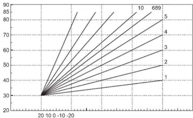
7
SEPARATELY SETTABLE FOR EACH INDIVIDUAL ZONE:
THE CURVES (FROM 1 TO 10) ARE CHOSEN WITH THE PARAMETERS:
P05 = CURVE ZONE 1
P11 = CURVE ZONE 2
P17 = CURVE ZONE 3
THE OFFSET (PARALLEL OFFSET) IS CHOSEN FOR EACH INDIVIDUAL ZONE WITH THE PARAMETERS:
P06 = OFFSET ZONE 1
P12 = OFFSET ZONE 2
P18 = OFFSET ZONE 3
OFFSET = 20 OFFSET = 40
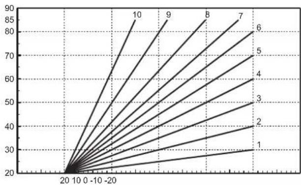
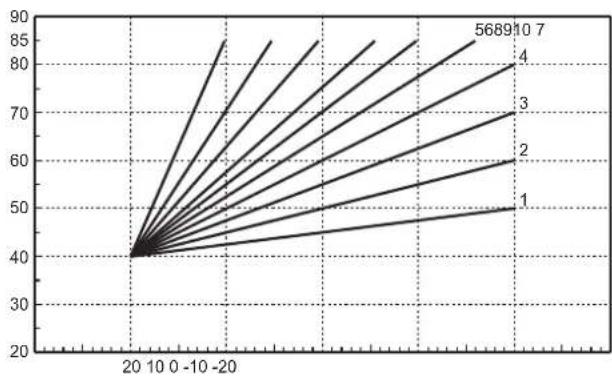
In case of external probe fault (error F73), the system will work with the set heating setpoint.
1. VUE D'ENSEMBLE
VUE EXTÉRIEURE ET DIMENSIONS BOÎTIER
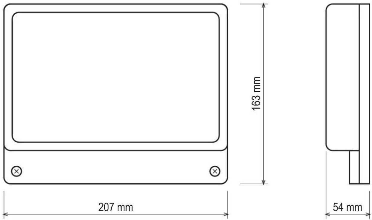
Fig. 1
VUE INTÉRIEURE CARTE
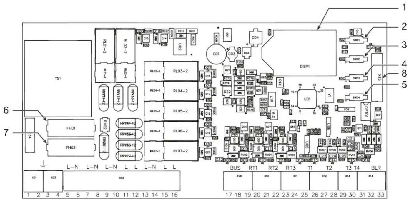
Fig. 2
Légende
1 Afficheur LCD
5 Touche CONFIGURATION AUTOMATIQUE
2 Touche +
Fig. 3
![graph TD A["Device"] --> B{Symbol} B --> C["Circle Symbol"] C --> D["Device"] D --> E["Device"] E --> F["Device"] F --> G["Device"] G --> H["Device"] H --> I["Device"] I --> J["Device"] J --> K["Device"] K --> L["Device"] L --> M["Device"] M --> N["Device"] N --> O["Device"] O --> P["Device"] P -->…](/content/2026/03/549582/images/70c24c95e9486d7615b05d4eb92cd2e63282f6e42bfc5578f112302da0850450.jpg)
Fig. 4
2.3 BORNAGE
Fig. 14
c. Temps post-circulation
c. Temps post-circulation
c. Temps post-circulation
c. Temps post-circulation
c. Temps post-circulation
fig. 3
![graph TD A["Device"] --> B{Symbol} B --> C["Circle"] C --> D["Switch"] style C stroke:#000,stroke-width:2px style D stroke:#000,stroke-width:2px](/content/2026/03/549582/images/d300676e8a3a484553ee162c5bd2eb89a526771a71752826c9997b4eb22e5aae.jpg)
fi g. 4
fig. 16
5.2.1 Termostato on/off
5.18.1 Termostato on/off
5.20.1 Termostato on/off
5.22.1 Termostato on/off
5.24.1 Termostato on/off
5.26.1 Termostato on/off
6.1.1 Termostato on/off
Bomba de zona
6.2.1 Termostato on/off
6.18.1 Termostato on/off
6.20.1 Termostato on/off
6.22.1 Termostato on/off
6.24.1 Termostato on/off
6.26.1 Termostato on/off
Abb. 3
![graph TD A["Input"] --> B["Processing Node"] B --> C["Output"] style B fill:#f9f,stroke:#333 style C fill:#ccf,stroke:#333](/content/2026/03/549582/images/1c708cac832befb50c1552e44d81e7683f00d3375b3473b0ed3d9e0782e830de.jpg)
Abb. 4
Abb. 14
5.20.1 Thermostat on/off
5.26.1 Thermostat on/off
6.20.1 Thermostat on/off
6.22.1 Thermostat on/off
OFFSET = 40
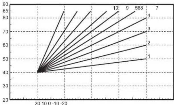
- INSTALLATION....66
- FIRST STARTUP (AUTOCONFIGURATION)......82
- OPERATION 83
- STAND ALONE 1" CONFIGURATIONS....84
- 6 "STAND ALONE 2" CONFIGURATIONS....99
- 7 "COMMUNICATING" CONFIGURATIONS....115
- 8 SERVICE MENU 115
- 9 INDICATIONS DURING OPERATION 117
- 10 ADDITIONAL FUNCTIONS.... 117
- TABLE DES MATIÈRES
- VUE D'ENSEMBLE....120
- INSTALLATION....122
- PREMIÈRE MISE EN MARCHE (CONFIGURATION AUTOMATIQUE) 138
- FONCTIONNEMENT....139
- INSTALLATION....236
- ERSTE INBETRIEBNAHME (AUTOKONFIGURATION....252
- BETRIEB....253
- KONFIGURATIONEN "STAND-ALONE 1" 254
- 5.2.1 TERMOSTATO ON/OFF
- 5.18.1 TERMOSTATO ON/OFF
- 5.20.1 TERMOSTATO ON/OFF
- 5.22.1 TERMOSTATO ON/OFF
- 5.24.1 TERMOSTATO ON/OFF
- 5.26.1 TERMOSTATO ON/OFF
- 6.1.1 TERMOSTATO ON/OFF
- POMPA DI ZONA
- 6.2.1 TERMOSTATO ON/OFF
- 6.18.1 TERMOSTATO ON/OFF
- 6.20.1 TERMOSTATO ON/OFF
- 6.22.1 TERMOSTATO ON/OFF
- 6.24.1 TERMOSTATO ON/OFF
- 6.26.1 TERMOSTATO ON/OFF
- IMPOSTABILE SEPARATAMENTE PER OGNI SINGOLA ZONA
- KEY
- GENERAL DESCRIPTION
- INSTALLATION
- 2.1 ASSEMBLY
- ATTENTION
- 2.2 INSTALLATION
- 2.3 ASSIGNING OF TERMINALS
- GENERATOR DEMAND
- COMMUNICATING: GENERATOR EQUIPPED WITH OPENTHERM PROTOCOL
- STAND ALONE 1: GENERATOR WITHOUT OPENTHERM PROTOCOL (ON/OFF)
- STAND ALONE 2: GENERATOR WITHOUT OPENTHERM PROTOCOL (ON/OFF) WITH TEMPERATURE CONTROL
- ELECTRICAL CONNECTIONS
- SCHEMATIC DIAGRAM
- FIRST STARTUP (AUTOCONFIGURATION)
- OPERATION
- STAND ALONE 1" CONFI IGURATIONS WITHOUT DHW
- STAND ALONE 1" CONFI IGURATIONS WITH DHW (ON SYSTEM)
- STAND ALONE 2" CONFI IGURATIONS WITHOUT DHW
- STAND ALONE 2" CONFI IGURATIONS WITH DHW (ON SYSTEM)
- COMMUNICATING" CONFIGURATIONS WITH DHW (INTEGRATED IN BOILER)
- COMMUNICATING" CONFI GURATIONS WITH DHW (ON SYSTEM)
- STAND ALONE 1" CONFIGURATIONS
- 5.1 "ONE DIRECT ZONE – NO EXTERNAL SENSOR
- 5.1.1 ON/OFF THERMOSTAT
- ZONE PUMP
- ZONE VALVE
- ALGORITHM
- 5.1.2 REMOTE CONTROL
- 5.2 "ONE DIRECT ZONE – WITH EXTERNAL SENSOR
- 5.2.1 ON/OFF THERMOSTAT
- 5.2.2 REMOTE CONTROL
- 5.3 "TWO DIRECT ZONES - NO EXTERNAL SENSOR
- WHAT CHANGES IS
- 5.4 "TWO DIRECT ZONES – WITH EXTERNAL SENSOR
- 5.5 "THREE DIRECT ZONES - NO EXTERNAL SENSOR
- 5.6 "THREE DIRECT ZONES – WITH EXTERNAL SENSOR
- 5.7 "ONE MIXED ZONE - NO EXTERNAL SENSOR
- 5.7.1 ON/OFF THERMOSTAT
- 5.7.2 REMOTE CONTROL
- 5.8 "ONE MIXED ZONE – WITH EXTERNAL SENSOR
- 5.8.1 ON/OFF THERMOSTAT
- 5.8.2 REMOTE CONTROL
- 5.9 "TWO MIXED ZONES – NO EXTERNAL SENSOR
- 5.10 "TWO MIXED ZONES – WITH EXTERNAL SENSOR
- 5.11 "ONE MIXED ZONE AND ONE DIRECT ZONE - NO EXTERNAL SENSOR
- 5.12 "ONE MIXED ZONE AND ONE DIRECT ZONE - WITH EXTERNAL SENSOR
- 5.13 "ONE MIXED ZONE AND TWO DIRECT ZONES - NO EXTERNAL SENSOR
- 5.14 "ONE MIXED ZONE AND TWO DIRECT ZONES - WITH EXTERNAL SENSOR
- 5.15 "TWO MIXED ZONES AND ONE DIRECT ZONE - NO EXTERNAL SENSOR
- 5.16 "TWO MIXED ZONES AND ONE DIRECT ZONE - WITH EXTERNAL SENSOR
- 5.17 "ONE HOT WATER TANK
- 5.18 "ONE DIRECT ZONE AND ONE HOT WATER TANK - NO EXTERNAL SENSOR
- 5.18.1 ON/OFF THERMOSTAT
- 5.18.2 REMOTE CONTROL
- 5.19 "ONE DIRECT ZONE AND ONE HOT WATER TANK - WITH EXTERNAL SENSOR
- 5.20 "TWO DIRECT ZONES AND ONE HOT WATER TANK - NO EXTERNAL SENSOR
- 5.20.1 ON/OFF THERMOSTAT
- 15.20.2 REMOTE CONTROL
- 5.21 "TWO DIRECT ZONES AND ONE HOT WATER TANK - WITH EXTERNAL SENSOR
- 5.22 "THREE DIRECT ZONES AND ONE HOT WATER TANK - NO EXTERNAL SENSOR
- 5.22.1 ON/OFF THERMOSTAT
- 5.22.2 REMOTE CONTROL
- 5.23 "THREE DIRECT ZONES AND ONE HOT WATER TANK – WITH EXTERNAL SENSOR
- 5.24 "ONE MIXED ZONE AND ONE HOT WATER TANK - NO EXTERNAL SENSOR
- 5.24.1 ON/OFF THERMOSTAT
- 5.24.2 REMOTE CONTROL
- 5.25 "ONE MIXED ZONE AND ONE HOT WATER TANK - WITH EXTERNAL SENSOR
- 5.26 "ONE MIXED ZONE, ONE DIRECT ZONE AND ONE HOT WATER TANK - NO EXTERNAL SENSOR
- 5.26.1 ON/OFF THERMOSTAT
- 5.26.2 REMOTE CONTROL
- 5.27 "ONE MIXED ZONE, ONE DIRECT ZONE AND ONE HOT WATER TANK - WITH EXTERNAL SENSOR
- 6 "STAND ALONE 2" CONFIGURATIONS
- 6.1 "ONE DIRECT ZONE - NO EXTERNAL SENSOR
- 6.1.1 ON/OFF THERMOSTAT
- 6.1.2 REMOTE CONTROL
- 6.2 "ONE DIRECT ZONE – WITH EXTERNAL SENSOR
- 6.2.1 ON/OFF THERMOSTAT
- 6.2.2 REMOTE CONTROL
- 6.3 "TWO DIRECT ZONES - NO EXTERNAL SENSOR
- 6.4 "TWO DIRECT ZONES – WITH EXTERNAL SENSOR
- 6.5 "THREE DIRECT ZONES - NO EXTERNAL SENSOR
- 6.6 "THREE DIRECT ZONES – WITH EXTERNAL SENSOR
- 6.7 "ONE MIXED ZONE - NO EXTERNAL SENSOR
- 6.7.1 ON/OFF THERMOSTAT
- 6.7.2 REMOTE CONTROL
- 6.8 "ONE MIXED ZONE – WITH EXTERNAL SENSOR
- 6.8.1 ON/OFF THERMOSTAT
- 6.8.2 REMOTE CONTROL
- 6.9 "TWO MIXED ZONES - NO EXTERNAL SENSOR
- 6.10 "TWO MIXED ZONES – WITH EXTERNAL SENSOR
- 6.11 "ONE MIXED ZONE AND ONE DIRECT ZONE - NO EXTERNAL SENSOR
- 6.12 "ONE MIXED ZONE AND ONE DIRECT ZONE - WITH EXTERNAL SENSOR
- 6.13 "ONE MIXED ZONE AND TWO DIRECT ZONES - NO EXTERNAL SENSOR
- 6.14 "ONE MIXED ZONE AND TWO DIRECT ZONES - WITH EXTERNAL SENSOR
- 6.15 "TWO MIXED ZONES AND ONE DIRECT ZONE - NO EXTERNAL SENSOR
- 6.16 "TWO MIXED ZONES AND ONE DIRECT ZONE - WITH EXTERNAL SENSOR
- 6.17 "ONE HOT WATER TANK
- 6.18 "ONE DIRECT ZONE AND ONE HOT WATER TANK - NO EXTERNAL SENSOR
- 6.18.1 ON/OFF THERMOSTAT
- 6.18.2 REMOTE CONTROL
- 6.19 "ONE DIRECT ZONE AND ONE HOT WATER TANK - WITH EXTERNAL SENSOR
- 6.20 "TWO DIRECT ZONES AND ONE HOT WATER TANK - NO EXTERNAL SENSOR
- 6.20.1 ON/OFF THERMOSTAT
- 6.20.2 REMOTE CONTROL
- 6.21 "TWO DIRECT ZONES AND ONE HOT WATER TANK - WITH EXTERNAL SENSOR
- 6.22 "THREE DIRECT ZONES AND ONE HOT WATER TANK - NO EXTERNAL SENSOR
- 6.22.1 ON/OFF THERMOSTAT
- 6.22.2 REMOTE CONTROL
- 6.23 "THREE DIRECT ZONES AND ONE HOT WATER TANK – WITH EXTERNAL SENSOR
- 6.24 "ONE MIXED ZONE AND ONE HOT WATER TANK - NO EXTERNAL SENSOR
- 6.24.1 ON/OFF THERMOSTAT
- 6.24.2 REMOTE CONTROL
- 6.25 "ONE MIXED ZONE AND ONE HOT WATER TANK – WITH EXTERNAL SENSOR
- 6.26 "ONE MIXED ZONE, ONE DIRECT ZONE AND ONE HOT WATER TANK - NO EXTERNAL SENSOR
- 6.26.1 ON/OFF THERMOSTAT
- 6.26.2 REMOTE CONTROL
- 6.27 "ONE MIXED ZONE, ONE DIRECT ZONE AND ONE HOT WATER TANK – WITH EXTERNAL SENSOR
- 7 "COMMUNICATING" CONFIGURATIONS
- 7.1 "COMMUNICATING" CONFIGURATIONS WITH DHW (INTEGRATED IN BOILER)
- 8 SERVICE MENU
- HI" - HISTORY MENU
- RE" - HISTORY RESET
- 9 INDICATIONS DURING OPERATION
- 9.1 LCD DISPLAY OFF
- 10 ADDITIONAL FUNCTIONS
- 10.1 FH MODE
- 10.2 EQUAL SETTINGS FOR EACH ZONE (TSP30)
- 10.3 PUMP ACTIVATION WITH CARD IN STANDBY (TSP34)
- 10.4 HEATING DELIVERY PROBE ENABLING (TSP35)
- 10.5 OPERATION WITH BOILER IN FAULT STATUS (TSP36)
- 10.6 LEGIONELLA PROTECTION (TSP37)
- 10.7 BOILER SUMMER/WINTER MODE (TSP38)
- 10.8 ANTIBLOCKING
- 10.8.1 CIRCULATING PUMP ANTIBLOCKING
- 10.8.2 MIXING VALVE ANTIBLOCKING
- 10.9 SENSOR CHARACTERISTICS
- 10.10 USER SETTINGS
- 10.11 EXTERNAL PROBE/ SLIDING TEMPERATURE
- SEPARATELY SETTABLE FOR EACH INDIVIDUAL ZONE
- VUE D'ENSEMBLE
- LÉGENDE
- 2.3 BORNAGE
- BOMBA DE ZONA
- 5.20.1 THERMOSTAT ON/OFF
- 5.26.1 THERMOSTAT ON/OFF
- 6.20.1 THERMOSTAT ON/OFF
- 6.22.1 THERMOSTAT ON/OFF
Brand : FERROLI
Model : FZ4
Category : Heating controller