
FCM - Uncategorized FERROLI - Free user manual and instructions
Find the device manual for free FCM FERROLI in PDF.


| Brand | Ferroli |
| Model | FCM (Fan Coil Cassette) |
| Product Type | Ceiling-mounted cassette fan coil unit |
| Versions Available | 2-pipe (400, 600, 850, 1500) and 4-pipe (400-4T, 750-4T) |
| Power Supply | 230 V, 1-phase, 50 Hz |
| Cooling Capacity (Max) | 3.93 – 10.64 kW (2-pipe); 2.88 – 5.18 kW (4-pipe) |
| Heating Capacity (Max) | 5.34 – 14.38 kW (2-pipe); 4.73 – 7.41 kW (4-pipe) |
| Air Flow (Max) | 717 – 1850 m³/h (2-pipe); 717 – 1233 m³/h (4-pipe) |
| Sound Pressure Level (Max) | 40 – 50 dB(A) |
| Pipe Connections | 3/4" for main coil; 1/2" for secondary coil (4-pipe models) |
| Condensate Drain | Rigid PVC 32 mm inner tube; pump included (max lift 500 mm for 400 models, 750 mm for others) |
| Net Weight (Body) | 16.5 – 29 kg (depending on model) |
| Net Weight (Panel) | 2.5 – 6 kg |
| Dimensions (Body, L×A×P) | 655×290×655 mm (400) to 900×330×900 mm (1500) |
| Dimensions (Panel, L×A×P) | 715×123×715 mm (400) to 1035×90×1035 mm (1500) |
| Fan Speeds | 3 speeds (Low, Medium, High) |
| Control Options | Remote control (included), optional wall-mounted panels (REM W1) |
| Valve Requirement | 3-way valve obligatory for cooling mode to prevent condensation |
| Mounting | Ceiling suspended using brackets and threaded rods (M10 nuts and washers supplied) |
| Filter | Washable filter housed in the grille |
| Safety Standards | CE mark, complies with Low Voltage Directive 2006/95/EC, EMC 2004/108/EC, RoHS 2002/95/EC |
| Accessories Included | Cardboard template, bolts M6, hose, insulating tube, metal clamp, remote control, manuals |
Frequently Asked Questions - FCM FERROLI
User questions about FCM FERROLI
0 question about this device. Answer the ones you know or ask your own.
Ask a new question about this device
Download the instructions for your Uncategorized in PDF format for free! Find your manual FCM - FERROLI and take your electronic device back in hand. On this page are published all the documents necessary for the use of your device. FCM by FERROLI.
USER MANUAL FCM FERROLI
Fan coil cassette EC
Fan coil de tipo cassette EC
Fan coil cassette EC

CE
EN INSTALLATION MANUAL
Gentile cliente,
Thank you for having purchased a FERROLI product. It is the result of many years of experiences and of particular research studies and has been made with top quality materials and advanced technologies. The CE mark guarantees that the products satisfy all the applicable European Directives.
The qualitative level is kept under constant control and FERROLI products therefore offer SAFETY, QUALITY and RELIABILITY. Due to the continuous improvements in technologies and materials, the product specification as well as performances are subject to variations without prior notice.
Thank you once again for your preference
FERROLI
S.p.A
The manufacturer declines all responsibility for any inaccuracies in this manual due to printing or typing errors. The manufacturer reserves the right to modify the products contents in this catalogue without previous notice.
SOMMARIO
INTRODUZIONE 4
DIRETTIVE EUROPEE....4
CARATTERISTICHE ....5
SCOPO DELLA MACCHINA 5
VERSIONI DISPONIBILI ....5

Attacchi idraulici

Scarico condensa
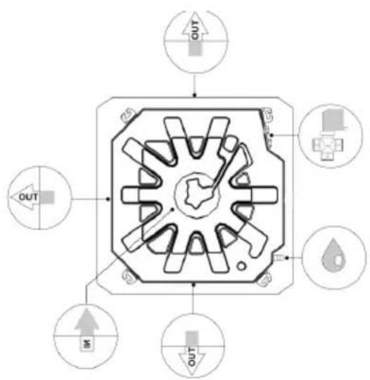
Fig. 5

Fig. 6
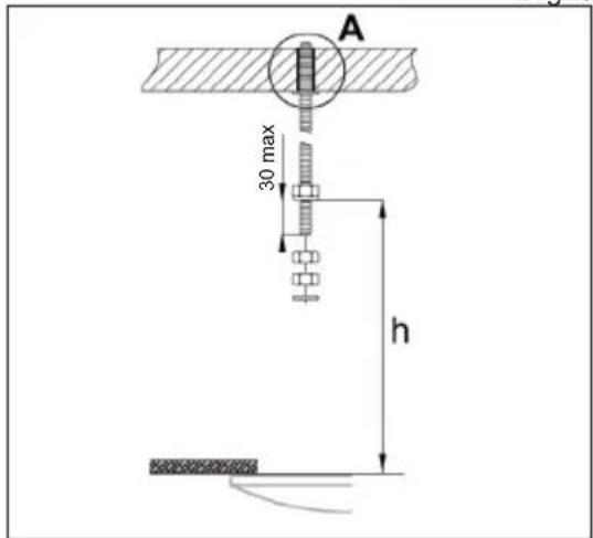
Fig. 7

Fig. 8

Fig. 9

INSTALLAZIONE
COLLEGAMENTI IDRAULICI
COLLEGAMENTI SCARICO CONDENSA
INSTALLAZIONE
Fig. 2

Fig. 3

Fig. 4

Fig. 5
VERSIONES DISPONIBLES....5


Conexiones agua
Fig. 5

Fig. 6

Fig. 7

Fig. 8

Fig. 9

INSTALACIÓN
CONEXIONES DE AGUA

D

INSTALACIÓN
Fig. 2
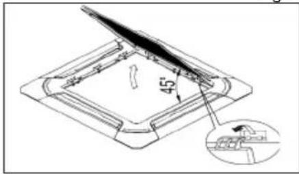
Fig. 3

Fig. 4

Fig. 5

DECLARATION OF CONFORMITY 4
PURPOSE OF THE MACHINE 5
AVAILABLE VERSIONS 5
DESCRIPTION OF THE MAIN COMPONENTS....5
AVAILABLE ACCESSORIES....7
INSTALLATION....8
DIMENSIONS FOR INSTALLING MODELS: 400 400-4T 8
DIMENSIONS FOR INSTALLING MODELS: 600 e 750-4T 850 1500....9
SAFETY REGULATIONS 10
PRELIMINARY OPERATIONS PRIOR TO INSTALLATION 10
ACCESSORIES SUPPLIED AT THE CORRECT OF UNITS 10
TOOLS REQUIRED FOR INSTALLATION 11
ACCESSORY PARTS NORMALLY AVAILABLE ON THE MARKET AND REQUIRED FOR INSTALLATION . . .11
CHOICE OF THE INSTALLATION SITE 11
BEFORE INSTALLATION 12
HOW TO INSTALL THE APPLIANCE....13
CONNECTIONS 14
PIPES AND DRAINING OFF CONDENSATION....14
EVACUATION OF AIR DURING THE FILLING OF THE PLAN 15
NOTES ABOUT VALVE ACTIVATION....15
INSTALLATION BACINELLA CONDENSA COLLECTION 15
GRILLE INSTALLATION 16
Procedure for connecting the unit 17
CONNECTION DIAGRAMS 18
OPTIONS INSTALLATIONS 19
PRELIMINARY INSPECTIONS PRIOR TO STARTING 19
TROUBLESHOOTING....20
TROUBLESHOOTING 20
INTRODUCTION
DECLARATION OF CONFORMITY
The manufacturer declares that the machines described in this instruction manual meet the requirements of the following directives and subsequent modifications:
- Low voltage directive 2006/95/EC;
• Electromagnetic compatibility directive 2004/108/EC;
• Directive 2002/95/EC RoHS.
It conforms to what is stated in the legislation
• EN 60335-2-40
• EN 60335-1
• EN 55014-1
• EN 55014-2
• EN 61000-3-2
• EN 6100-3-3

GENERAL SPECIFICATIONS
PURPOSE OF THE MACHINE
The cassette convector fan is a terminal appliance that treats the air in a room both in the summer and winter. The appliance must be installed on the ceiling. It is equipped with a very pleasantly designed grille.
AVAILABLE VERSIONS
This new series of cassette type convector fans is available in the version with 2 pipes in 4 sizes and 3.93 to 10.64 kW nominal cooling capacity ratings and in the version with 4 pipes (-4T) in 2 sizes with 2.88 to 5.18 kW nominal cooling capacity ratings.
DESCRIPTION OF THE MAIN COMPONENTS
| UNITA' VERSIONE | |
| 400 | 2 TUBI |
| 600 | |
| 850 | |
| 1500 | |
| 400-4 | 4 TUBI |
| 750-4 | |
The unit consists of a module or main structure containing a finned exchanger, the ventilating unit formed by a three speed motor and a centrifugal axial fan, a tray to collect the condensation equipped with a pump to drain this off.
Applied externally houses the electrical box.
The unit also has a grille made of thermoplastic material and formed by a frame which houses the filter and air flow directing fins plus an intake grille: the air flow directing fins are installed on each side of the grille and can be positioned by remote control. The intake grille is fixed in a practical way that allows it to be easily inspected for servicing and filter cleaning operations.
GENERAL VIEW OF THE UNIT
The drawings below highlight the fundamental parts of the unit.
It is reported:
Unit: Includes battery, fan assembly, pump and electrical box
Panel: Plastic material includes frame, grille and air filter, air orientation vents and signal receiver from the remote control.
Brackets: arranged on four corners of the unit serve for the suspension and fastening of the unit.
Condensate discharge pipe: for the evacuation of the condensate that is formed in cold operation.
Air vent valves: placed on the upper manifold allows the evacuation of the air in the system.
Exhaust Valve: present on the lower manifold allows water drainage from the plant.
Hole for connecting with auxiliary basin: bring the water on the auxiliary basin to the main basin and then evacuate it from the pump.
Fig. 1

GENERAL SPECIFICATIONS
| MODELS 400 600 850 1500 400-4 750-4 U.M | ||||||||
| Version 2 pipes 4 pipes \ | ||||||||
| Power supply 230-1-50 V-f-Hz | ||||||||
| Max 717 1133 1441 1850 717 1233 m3/h | ||||||||
| Air Flow | Med 502 793 1009 1295 502 863 m3/h | |||||||
| Min | 359 567 721 925 359 617 m3/h | |||||||
| Max | 3930 | 5580 | 6840 | 10640 | 2880 | 5180 | W | |
| Cooling capacity (1) | Med | 3070 4350 5330 8090 2190 3940 | W | |||||
| Min | 2480 3520 4300 6600 1800 3260 W | |||||||
| Water flow | 676 960 1176 1830 495 891 l/h | |||||||
| Cooling water pressure drop | 12 | 21 | 27 | 34 | 14,5 | 12 | kPa | |
| Max | 5340 | 7720 | 9370 | 14380 | \ | \ | W | |
| Heating Capacity (2) | Med | 4000 | 5920 | 7250 | 11290 | \ | \ | W |
| Min | 3150 | 4500 | 5500 | 8440 | \ | \ | W | |
| Max | \ | \ | \ | \ | 4730 | 7410 | W | |
| Heating Capacity (3) | Med | \ | \ | \ | \ | 3600 | 5640 | W |
| Min | \ | \ | \ | \ | 2980 | 4670 | W | |
| Water flow (2) | 676 | 960 | 1176 | 1830 | \ | \ | m3/h | |
| Water flow (3) | \ | \ | \ | \ | 407 | 637 | m3/h | |
| Heating water pressure drop | 10,6 | 22 | 23 | 34 | 29,1 | 42 | kPa | |
| Power input | 27 | 42 | 70 | 124 | 27 | 50 | W | |
| Max | 40 | 42 | 46 | 50 | 40 | 42 | dB(A) | |
| Sound pressure level | Med | 36 | 33 | 36 | 40 | 36 | 34 | dB(A) |
| Min | 28 | 26 | 28 | 33 | 28 | 26 | dB(A) | |
| Pipe connection | 3/4" | 3/4" | 3/4" | 3/4" | 3/4" | 3/4" | “ | |
| Pipe connection auxiliary | \ | \ | \ | \ | 1/2" | 1/2" | “ | |
| Net \ Gross weight Body | 16.5/21.5 | 23/28 | 27/33 | 29/34.5 | 17/23 | 28/34 | Kg | |
| Net \ Gross weight Panel | 2.5/4.5 6/9 | 6/9 | 6/9 2.5/4.5 6/9 | Kg | ||||
| L 655 900 900 655 900 mm | ||||||||
| Packing Body dimension | A 290 | 260 330 330 290 330 mm | ||||||
| P 655 | 900 900 900 655 900 mm | |||||||
| L 715 1035 1035 1035 715 1035 mm | ||||||||
| Packing Panel dimension | A | 123 | 90 | 90 | 90 | 123 | 90 | mm |
| P 715 1035 1035 715 1035 mm | ||||||||
NOTE:
(1) Air T=27°C D.B. / 19°C W.B., Water IN/OUT 7°/12°C, design air flow; For medium and low fan speed, water flow as in maximum fan speed mode.
(2) Air T=20°C D.B., water inlet temperature 50°C, water flow as in cooling mode.
(3) Air T=20°C D.B., water IN/OUT 70°/60°C, design air flow; For medium and low fan speed, water flow as in maximum fan speed mode.
(4) Sound pressure level in 100m2 room with 0.5sec of reverberation time
ACCESSORIES
AVAILABLE ACCESSORIES
The following accessories are available for this category:
- Control and Monitoring Panels REM W1
A set of panels is available for remote wall installation formed by three different types of control: commutator, basic thermostat and evolved thermostat.
- 3-way valve (obligatory for operation in the cooling mode)
The three-way valve is not only required to control the ambient temperature, but also to block the flow of chilled water to the coil if the level of condensed water in the tray should rise in an abnormal way.
It is obligatory to install this valve if the unit is used for operation in the Cooling mode during summer as this stops it from cooling too much during the periods when the fan remains at a standstill, thus preventing the unpleasant formation of condensation on the casing of the machine.
The dimensions are given in mm.

| MOD. Unit weight Grille weight | ||
| 400 400-4T | 16.5 2.5 | |
HYDRAULIC CONNECTIONS
1- Main cold battery input
2- Cold water main output battery
3 - Secondary battery hot water inlet
4- Secondary battery outlet hot water
5- Condensate drain outlet
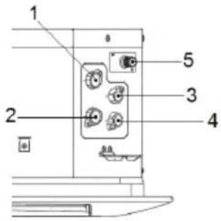
Mod. 400 (2 tubi) Mod 400 (4 tubi)


| Mod Size of main coil connections [∅] Size of secondary coil connections [∅] | ||
| 400 3/4" - | ||
| 400-4T 3/4" 1/2" | ||
INSTALLATION
DIMENSIONS FOR INSTALLING MODELS: 600 e 750-4T 850 1500
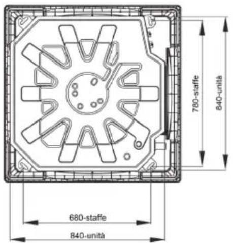

The dimensions are given in mm.
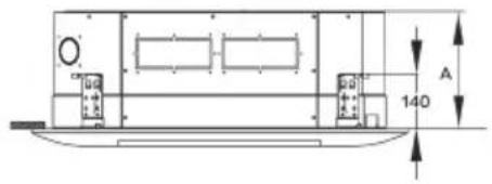
| MOD. A [mm] B [mm] Unit weight Grille weight | ||||
| 600 230 170 23 6 | ||||
| 750-4T 850 | 300 190 | 27 6 | ||
| 1500 300 | 190 29 6 | |||
HYDRAULIC CONNECTIONS
1- Main cold battery input
2- Cold water main output battery
3 - Secondary battery hot water inlet
4- Secondary battery outlet hot water
5- Condensate drain outlet

Mod 600 - 850 - 1500 (2 tubi) Mod 750 (4 tubi)
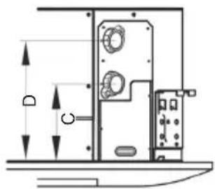
| MOD. | C [mm] | D [mm] |
| 600 | 145 | 195 |
| 850 - 1500 | 155 | 205 |
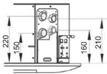
| MODELLO Size of main coil connections [∅] Size of secondary coil connections [∅] | ||
| 600 3/4" | - | |
| 850 3/4" | - | |
| 1500 | 3/4" | - |
| 750-4T | 3/4" | 1/2" |
INSTALLATION
SAFETY REGULATIONS
The manufacturer declines all liability for failure to comply with the safety regulations and recommendations described below. The manufacturer also declines all liability for damage caused by improper use of the convector fan and/or by modifications made without authorization.
The convector fan must be installed by expert, authorized personnel.
· Wear adequate safety clothing when installing the machine, e.g. goggles, gloves, etc.
· Work in a safe, clean and uncluttered place when installing the appliance.
· Comply with the laws in force in the country where the convector fan is installed during use and when disposing of the packaging materials and products used to clean and service the appliance. Also comply with the instructions given by the manufacturers of such products.
- Comply with the pertinent anti-pollution laws if the convector fan is dismantled.
- It is absolutely forbidden to touch moving parts or to get between the same.
- Before starting the convector fan, make sure that its parts and the whole system are in a perfect condition.
- Spare parts must comply with the requirements established by the manufacturer. Only use genuine spare parts.
- It is absolutely forbidden to touch moving parts or to move between the same.
- Only qualified personnel may be allowed to service or replace damaged or worn parts of the convector fan. Moreover, such work must be carried out in compliance with the instructions in this manual.
- before proceeding with the servicing or cleaning operations, make sure that the unit is not connected to the electricity main and that it cannot be accidentally powered.
This installation manual must be read, memorized and kept ready to hand throughout the life of the convector fan.
PRELIMINARY OPERATIONS PRIOR TO INSTALLATION
Comply with the following instructions before beginning to install the appliance:
· Make sure that all parts of the convector fan are in a perfect condition.
- Make sure that the appliance has not sustained damage during transport. Immediately notify the haulage contractor if damage is discovered. Check to make sure that the accessories required for installation and the relative documentation are included in the pack. As a further safeguard, the grille is supplied in a separate pack. Remote control kits (if applicable) are also wrapped separately.
- Convey the packed appliance as near to the installation site as possible.
· Do not stack weights or place tools on top of the packed appliance.
ACCESSORIES SUPPLIED AT THE CORRECT OF UNITS
All units are supplied with a range of accessories for proper installation and use.
Make sure that what is described is present in the packaging:
| Application Description Q,ty | ||
| Grid mounting | Cardboard template 1 | |
| Bolts M6 4 | ||
| Exhaust installation | Hose isolated 1 | |
| Insulating 1 | ||
| Metal clamp 1 | ||
| Insulation | Insulating tubes 2 | |
| Insulating | 4 | |
| Mounting units | Dadi M10 8 | |
| Washers 8 | ||
| Control | Remote control 1 | |
| Remote control port 1 | ||
| Manuals | Unit Installation Manual 1 | |
| Remote control user manual 1 |
INSTALLATION
TOOLS REQUIRED FOR INSTALLATION
The following tools are required in order to install the convector fan:
- Pipe wrench for the wet connections
-
Flat tip and cross-headed screwdrivers
· Drill
· Scissors -
Wire stripper
- Pipe cutters
· Pipe benders - Measuring tape
· Level
· Goggles and protective gloves
ACCESSORY PARTS NORMALLY AVAILABLE ON THE MARKET AND REQUIRED FOR INSTALLATION
The following items are also required for installation purposes:
· Water pipe unions
- Condensation-proof tape
· Adhesive tape
CHOICE OF THE INSTALLATION SITE
Positions to avoid:
- Places in direct sunlight.
- Positions near heat sources.
· Damp places and positions where the unit could come into contact with water (e.g.: washrooms). - Places where shelves or furniture could prevent the air from circulating correctly.
Fig. 1
What to do:
- Choose a position without obstructions that could hamper the air inlets and outlets.
- Choose a position where the appliance is easy to install.
- Choose a position that complies with the recommended minimum space for maintenance work.
- Choose a position that allows air to freely circulate around the room.
· Install the appliance so that the condensation can be easily drained off. - Choose a position possibly in the middle of the room. Adjustment of the outlet air can then be optimized to reach all parts of the room.
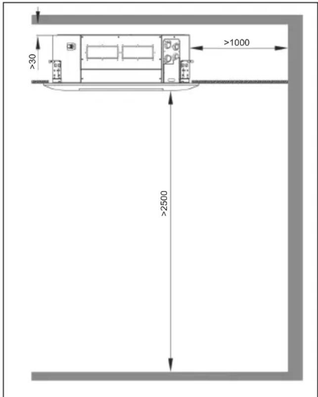
The best position of the fans is generally the one that allows air to be blown on to the ceiling by means of the Coanda effect. The fins can also be set in the fully closed position, with the limitations shown in the figure.
- Check to make sure that the chosen position allows the panels to be sufficiently removed from the ceiling to allow the installation and maintenance operations to be carried out.
- Do not install the appliance where water can drip on to it.
INSTALLATION
BEFORE INSTALLATION
Transporting the unit packed as close as possible to the place of installation.
IMPORTANT: Do not move the unit through the exhaust pipe of the condensate or attacks; grasp on the four corners.
The installation of the unit will be facilitated using un'elevatore
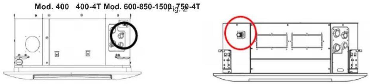
The fan must be installed in a position to allow routine maintenance and repairs, as well as access to the air vent valve on the side of the unit (housed in the water connections). (See figure 3 position indication hatch)
Fig. 2

Fig. 3
Mod. 400 400-4T Mod. 600-850-1500 750-4T
![graph TD A["OUT"] --> B["Central Device"] C["IN"] --> B D["OUT"] --> B E["IN"] --> B F["OUT"] --> B G["IN"] --> B H["OUT"] --> B I["IN"] --> B J["OUT"] --> B K["IN"] --> B L["OUT"] --> B M["IN"] --> B N["OUT"] --> B O["IN"] --> B P["OUT"] --> B Q["IN"] --> B R["OUT"] --> B S["IN"] --> B T["OUT"] -->…](/content/2026/05/764919/images/d3b316b6653043e730aea97b5c04ce9e0d546d28eea9e4316601a18c73080856.jpg)

Hydraulic connections
Condensate drain

Renewal air inlet
Air outlet to the adjacent room
INSTALLATION
HOW TO INSTALL THE APPLIANCE
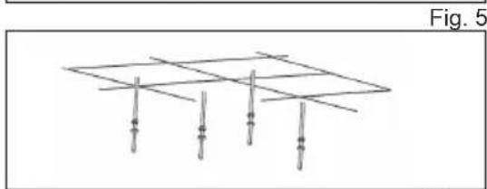
- Mark the position of each support, the connecting pipes and discharge of the condensate, of the electrical cables and power commands (see dimensions). The cardboard template can be supplied with help in this operation (Fig.4).
- Hang up the bearing brackets supplied with the appliance. Take care to keep them a certain distance (h) (Fig.6) from the false ceiling (See attached table). Do not tighten the nut or check nut. This will only be done after the unit is levelled, at the end of the installation phase.
Note: Depending on the type of ceiling, choose the most appropriate tie rods (Fig. 6A).
Remember the total weight for the different units.
| MOD. Weight [kg] h [mm] | ||
| 400 19 49 | ||
| 400-4T | 19.2 49 | |
| 600 29 140 | ||
| 750-4T | 33.5 140 | |
| 850 33 140 | ||
| 1500 35 140 | ||
Lift the unit (without the frame) carefully by gripping it on the four corners.
Match the side slots (1 Fig. 7) to the four brackets (2 Fig. 7).
Insert the brackets into the slots and screw the safety screws (Fig.8).
- Level the appliance with a level and allow 10-12 mm between the sheet metal casing and the lower surface of the false ceiling (Fig.9).
- Connect the condensation drain pipes and make the wet connections, then check to make sure that the appliance is still level.



INSTALLATION
CONNECTIONS
Fig. 1
The selection and sizing of the hydraulic lines is delegated responsibility for the designer who must operate under the rules of good practice and legislation.
- Position the hydraulic lines
- Tighten the connections using the "key against key" (Fig 1)
- Check for leakage
- Coat the connections with insulating material
The hydraulic lines and joints must be thermally insulated. Avoid partial insulation of pipes.
Do not over tighten to avoid damaging the insulation.

PIPES AND DRAINING OFF CONDENSATION
For the production of the condensate discharge pipe it is preferable to use a rigid PVC 32 mm inner tube.
The position of the trunks is shown in Fig.2.
- The units are equipped with a pump which is able to guarantee a rise in condensation water from the bottom of the unit (as shown in the figure) not exceeding 500 mm for the 400 and 400-4T models; and 750 mm for other models (Fig.3-A).
- To drain the water to a higher level of the unit, install an auxiliary condensate drain pump with collector tray and level regulator
-For a regular discharge of condensation it is necessary that the drain hose has an inclination of 1% downwards without bottlenecks or ascending tracts (Fig.3-B).
-In addition, have a deep siphon of at least 50 mm to prevent bad smells in the environment (Fig.3-C).
-For more than one unit installed in
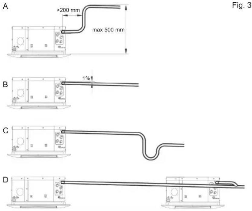
Fig. 3
a room, the condensate drainage pipe must be as in (Fig.3-D). The main manifold must be dimensioned to drain all the units at the same time.
-The pipes must be covered with anti-condensate materials, eg polyurethane, polypropylene, neoprene or expanded foils of 5-10 mm thick.
INSTALLATION
EVACUATION OF AIR DURING THE FILLING OF THE PLAN
- Open all system interception devices (manual or automatic);
- Start filling by slowly opening the water tap of the plant water;
- Operate (using a screwdriver) on the battery drain (Fig.1);
- When water starts bleeding from the breather valves of the appliance, close them and continue charging until the rated value for the plant is reached. Check the hydraulic sealing of the gaskets. It is advisable to repeat this operation after the appliance has been operating for several hours and periodically check the system pressure.
Fig. 1

NOTES ABOUT VALVE ACTIVATION
The appliance includes a condensation drain pump as part of the standard supply. Using a thermal contact sensor (TC), this pump always operates when the appliance is filled with cold water, thus in the cooling phase.
The pump remains stationary when the temperature of the water entering the bank exceeds 25\ °C and no condensation is formed. Connect the TC sensor to the cooling coil inlet pipe. If the valve kit accessory is used (this is obligatory if the unit is used for cooling), always place the sensor on the cooling exchanger inlet.
The valve can be controlled by means of the switch or the two thermostats supplied as accessories, depending on the type of installation.
INSTALLATION BACINELLA CONDENSA COLLECTION
Made of plastic material, it collects and conveys inside the main basin the condensate that forms on uninsulated hydraulic connections and valves kit (if present) during summer operation.
The mounting procedure is described in the instructions supplied with the basin.
Fig. 2

INSTALLATION
GRILLE INSTALLATION
Carefully unpack the assembly and check that it has not been damaged.
- Remove the grid:
-Alling the levers A on the grill at the same time unlock the grid (Fig.1)
- Open the 45° grid and unhook it from the frame (Fig.2) and unhook it from the frame
-
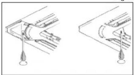
For units with removable covers, remove the cover for installation at the four corners (Fig.3)
-
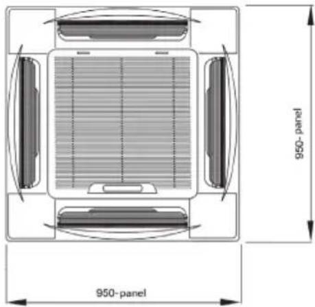
Installing the Panel (Fig.4)
Align the spindle motor A at the hydraulic connections in the B-box.
Temporarily fix the frame to the unit using the hooks (detail 1) on the four sides of the unit.
Center the panel against the false ceiling and check the horizontal trim.
Using a cross-head screwdriver, attach the frame to the unit. The position of the hardware depends on the models (Fig.5)
Fig. 1

Fig. 2
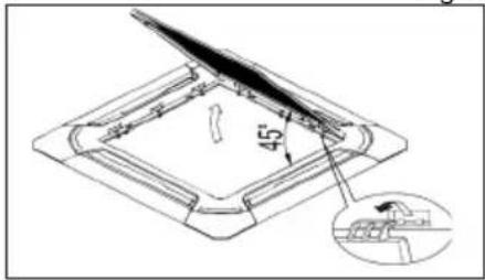
Fig. 3

Fig. 4

Fig. 5

Hang the grill for the air in the pan.
Connect the winder and the cable to the cassette electrically.
Replace the inlet air grille in the original position and electrically connect the receiver
For models with corner covers, replace the cover at the corners of the panel.
INSTALLATION
PROCEDURE FOR CONNECTING THE UNIT
IMPORTANT:
- The unit must be installed in accordance with national wiring rules.
- All cables with the unit, including accessories, must be type H05 VV-F, with PVC insulation according to EN 6033-2-40.
- Remove power to all circuits before accessing live parts.
- Connect the ground before the electrical connections.
According to the rules of installation, the device disconnects the power supply must provide a contact aperture (4 mm) that allows complete disconnection in the conditions of overvoltage category III.
The general scheme of the connections to be performed is shown in Fig.1
Fig. 1

For connection proceed as follows:
-Insert the power cord inside the machine from the cable gland shown in Fig.
-Remove the cover of the power cabinet by removing the locking screws.
-Inside the panels are the terminal blocks to which the connections are made, as shown in the Schemes section.
-Extended connections with the grid will be executed once the grid is mounted.
- Disconnect the electrical box cover

INSTALLATION
CONNECTION DIAGRAMS
Version 2 Tubes
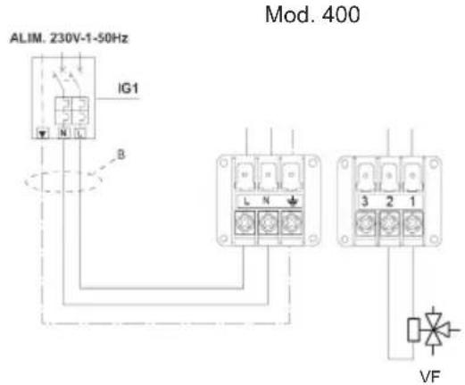
Mod. 600-850-1500
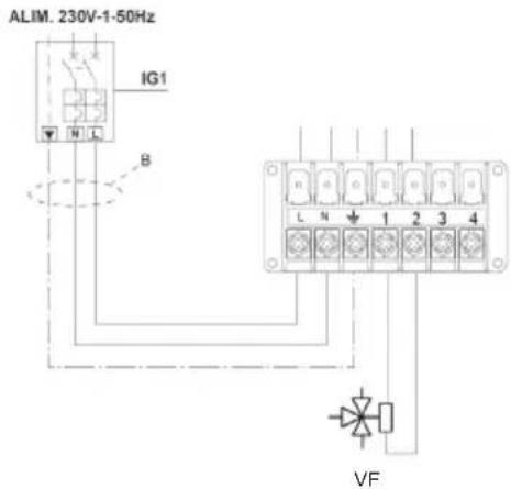
Version 4 Tubes

Mod. 750-4T

VF: Cold / Hot valve (for 2 pipes)
VC: Hot valve (for 4 pipes)
INSTALLATION
OPTIONS INSTALLATIONS
Air supply in a room:
The air flow to the adjacent space requires the closure of one or two flaps corresponding to the duct. On the partition wall between the conditional room, where the unit is installed, and the adjacent room, an air intake should be applied.

PRELIMINARY INSPECTIONS PRIOR TO STARTING
- The unit must not be started until the pipes have been cleaned and bled until all the air has been eliminated from the system.
· Make sure that the condensation drain pipes slope correctly.
· Make sure that the filter is clean and well seated in its housing. - Check the voltage and current values and compare them with the values on the data plate of the appliance. Check the electrical connections.
· Make sure that the delivery fins are not shut.
TROUBLESHOOTING
TROUBLESHOOTING
If there was an error condition during the unit running, a code will be displayed on the receiver. This code is identified by number of the system that caused the error or by an led combination. To interpret the error codes,
use the following table.
For models 400, 400-4T

| Error code displayed | Malfunction description | LED view | |||
| OPERATION | TIMER DEF | F./FAN ALARM | |||
| E2 Room temperature sensor is open or short-circuit x o x x | |||||
| E3/E4 Evaporator sensor is open or short-circuit | o x x x | ||||
| E7 EEPROM malfunction | o o x x | ||||
| E8 Water-level switch malfunction | x | x | x | o | |
x LED off
o LED lamp
For models 600, 750-4T, 850 and 1500

| Error code displayed | Malfunction description | LED view | |||
| OPERATION | TIMER | DEF./FAN | ALARM | ||
| E2 | Room temperature sensor is open or short-circuit | x | o | x | x |
| E3 | Evaporator sensor is open or short-circuit | o | x | x | x |
| E7 | EEPROM malfunction | o | o | x | x |
| EE | Water-level switch malfunction | x | x | x | o |
| E8 | Anomaly fan motor | o | x | o | x |
| PH | Error setting unit | x | x | o | o |
x LED off
o LED lamp
*Some alarms may be generated by a lack of ordinary maintenance. It's recommend to do this procedure before call the Technical Assistance.
- CE
- SOMMARIO
- INTRODUZIONE 4
- CARATTERISTICHE ....5
- INSTALLAZIONE
- COLLEGAMENTI IDRAULICI
- COLLEGAMENTI SCARICO CONDENSA
- INSTALACIÓN
- CONEXIONES DE AGUA
- INSTALLATION....8
- TROUBLESHOOTING....20
- INTRODUCTION
- DECLARATION OF CONFORMITY
- GENERAL SPECIFICATIONS
- PURPOSE OF THE MACHINE
- AVAILABLE VERSIONS
- DESCRIPTION OF THE MAIN COMPONENTS
- GENERAL VIEW OF THE UNIT
- ACCESSORIES
- AVAILABLE ACCESSORIES
- CONTROL AND MONITORING PANELS REM W1
- 3-WAY VALVE (OBLIGATORY FOR OPERATION IN THE COOLING MODE)
- HYDRAULIC CONNECTIONS
- INSTALLATION
- SAFETY REGULATIONS
- PRELIMINARY OPERATIONS PRIOR TO INSTALLATION
- ACCESSORIES SUPPLIED AT THE CORRECT OF UNITS
- TOOLS REQUIRED FOR INSTALLATION
- ACCESSORY PARTS NORMALLY AVAILABLE ON THE MARKET AND REQUIRED FOR INSTALLATION
- CHOICE OF THE INSTALLATION SITE
- POSITIONS TO AVOID
- WHAT TO DO
- BEFORE INSTALLATION
- HOW TO INSTALL THE APPLIANCE
- CONNECTIONS
- PIPES AND DRAINING OFF CONDENSATION
- EVACUATION OF AIR DURING THE FILLING OF THE PLAN
- NOTES ABOUT VALVE ACTIVATION
- INSTALLATION BACINELLA CONDENSA COLLECTION
- GRILLE INSTALLATION
- PROCEDURE FOR CONNECTING THE UNIT
- IMPORTANT
- CONNECTION DIAGRAMS
- OPTIONS INSTALLATIONS
- AIR SUPPLY IN A ROOM
- PRELIMINARY INSPECTIONS PRIOR TO STARTING
- TROUBLESHOOTING
Brand : FERROLI
Model : FCM
Category : Uncategorized