
SMI8YBS01D - Dishwasher BOSCH - Free user manual and instructions
Find the device manual for free SMI8YBS01D BOSCH in PDF.



| Product type | Freestanding or built-in dishwasher |
| Brand | Bosch |
| Model | SMI8YBS01D |
| Height (cm) | 86 (86 cm model) |
| Width (cm) | 60 |
| Depth (cm) | 60 |
| Weight (kg) | Approximately 45 |
| Electrical supply | 230 V, 50 Hz, 10 A |
| Capacity (place settings) | 14 |
| Wash programs | Eco, Auto, Intensive, Quick, etc. |
| Special functions | VarioDrawer, EmotionLight, TimeLight, Gap Illumination |
| Filtration system | Coarse filter, micro-filter, self-cleaning system |
| Spray arms | Upper, lower, and option for cooktop |
| Control panel | Electronic with display |
| Safety | Child lock, safety indicator, anti-overflow protection |
| Maintenance | Regular cleaning of filters, spray arms, and seals |
| Available spare parts | Filters, arms, seals, door, panel, etc. |
| Repairability | Detailed repair guide for the consumer |
| Sound level (dB) | 42 |
| Energy class | B (according to EU standard) |
Frequently Asked Questions - SMI8YBS01D BOSCH
User questions about SMI8YBS01D BOSCH
0 question about this device. Answer the ones you know or ask your own.
Ask a new question about this device
Download the instructions for your Dishwasher in PDF format for free! Find your manual SMI8YBS01D - BOSCH and take your electronic device back in hand. On this page are published all the documents necessary for the use of your device. SMI8YBS01D by BOSCH.
USER MANUAL SMI8YBS01D BOSCH
4.2 Mounting the appliance on the wall
4.2.1 Mounting the hanging rail for the 86-cm model 4.2.2 Mounting the fixing bracket for the wall 9 4.2.3 Mounting the built-in steam generator 10
4.3 Replacing the varioDrawer drawer 11
4.3.1 Removing the varioDrawer drawer 11 4.3.2 Mounting the varioDrawer drawer 12
4.4 Replacing the spray arm 13
4.4.1 Removing the spray arm 13 4.4.2 Mounting the spray arm 13
4.5 Replacing the filters 14
4.5.1 Removing the filter 14 4.5.2 Mounting the filters 14
4.6 Mounting the front panel for the table 15
4.7 Replacing the power cable 16
4.7.1 Disconnecting the power cable 16 4.7.2 Connecting the power cable 16
4.8 Replacing the detergent dispenser 17
4.8.1 Removing the detergent dispenser 17 4.8.2 Installing the spring 17 4.8.3 Mounting the detergent dispenser 17
4.9 Replacing the drain pump cover 18
4.9.1 Removing the drain pump cover 18 4.9.2 Mounting the drain pump cover 18
4.10 Replacing the door leaf 19
4.10.1 Removing the door leaf 19 4.10.2 Installing the door leaf 20
4.11 Replacing the outer door 21
4.11.1 Removing the outer door 21 4.11.2 Installing the outer door 21
4.12 Replacing the control panel 23
4.12.1 Removing the control panel 23 4.12.2 Installing the control panel 23
4.13 Fixing the spring-loaded door 24
4.14 Replacing the bottom panel 26
4.14.1 Removing the bottom panel 26 4.14.2 Installing the bottom panel 26
4.15 Replacing the main contact plate 27
4.15.1 Removing the main contact plate 27 4.15.2 Installing the main contact plate 27
4.16 Replacing the overflow pipe 28
4.16.1 Removing the overflow channel 28 4.16.2 Installing the overflow pipe 29
4.17 Replacing the inner door 31
4.17.1 Removing the inner door 31 4.17.2 Installing the inner door 31
4.18 Replacing the door hinge 32
4.18.1 Removing the door hinge 32 4.18.2 Installing the door hinge 32
4.19 Replacing the door seal (bottom) 34
4.19.1 Removing the door seal 34 4.19.2 Installing the door seal 35
4.20 Replacing the door seal (top) 36
4.20.1 Removing the door seal 36 4.20.2 Installing the door seal 36
Repair tips - DIY machine
4.21 Replacing EmotionLight 37
4.21.1 Removing EmotionLight 37 4.21.2 Installing EmotionLight 37
4.22 Replacing TimeLight 40
4.22.1 Removing TimeLight 40 4.22.2 Installing TimeLight 40
4.23 Replacing Gap illumination (product lighting) 41
4.23.1 Removing Gap illumination 41 4.23.2 Installing Gap illumination 42
About this document
1.1 Important information
1.1.1 General
These instructions for repair are intended for the user to repair the device themselves in accordance with the regulations for environmentally sound design of devices (from 03.2021).
They contain information on how to replace certain spare parts, including fuses and risks.
If you have any questions, please contact our customer service department. We are not liable for damage if the repair instructions have not been followed correctly.
1.2 Explanation of symbols
1.2.1 Hazard
Warnings are indicated by the symbol of a lightning bolt. The lightning bolt indicates the severity of the hazard.
| Ниво на п dedурждени 3начени | |
| ОПАСHОCT | Еспаразы新股у на п dedурждени.TО сбоб Shedени по Смьт ини сернони наразяваим. |
| ПРEDУПЕЖДЕНЕ | Еспаразы新股у на п dedурждени.TOT сбob Shedени по Смьт ини сернони наразяваим. |
| ВИМATEЛНО | Еспаразы新股у на п dedурждени.TOT сбob Shedени по Смьт ини наразяваим. |
| ВИМАМЕЛ | Еспаразы新股у на п dedурждени.TOT сбob Shedени по Смьт ини onMy-шостевни.$etп. |
Table 1: Hazard types
1.2.2 Hazard symbols
Hazard symbols are symbolic representations that provide information about the type of hazard.
The following hazard symbols are used in this document:
| Симboл за орасост за чужения | ОвноPre dedупраздітелно сьобсято Орасост от[elekntrочко наpopжени Риск OT[eк科研院所 |
| Орасost от[nорязвany |
Regarding this document
| Симbol 3a onachoct 3начени | Опachoct ot пемарази Опachoct ot горец поьрхости |
| Опachoct ot симно магнисто полес | |
| Опachoct ot неонисяцу льчени |
Table 2: Hazard symbols
1.2.3 Structure of warnings
The warnings in this document have a standardized structure.


DANGER
Immediate danger / warning
Safety measures to prevent danger.
Special symbol indicates warning of electric shock, parts under voltage. Follow instructions to avoid danger.


DANGER
Risk of electric shock from parts under voltage!
Electric shock
Disconnect electrical supply before servicing for at least 60 seconds.
1.2.4 General symbols
The following general symbols are used in this document:
| Оьш симвов Зачени | |
| I | Иденихицаре на спесиален сьвет (Текст w/ллграфика) |
| I | Иденихицаре на постс сьвет (самоTekст) |
| I | Иденихицаре на врьзka Кьм Вideоурок |
| I | Иденихицаре на необхочимite ИСТрумени |
| I | Иденихицаре на необхочимiteпраздарителни ус自主创新 |
| I | Иденихицаре на ус自主创新 (ako ...,Тогава ... ) |
| I | Иденихицаре на рezуntат |
| [Стар] | Иденихицаре на Клиочни 6ытуон |
| [00123456] | Иденихицаре на Кatableожен Homep |
| [Статус] | Иденихицаре на по��аизяп Текст/ празорец (надиспега на урEDA) |
Table 3: General symbols

Safety
2.1 General safety instructions
2.1.1 All household appliances
Danger of electric shock!
- Before repair work, including electrical components, disconnect the device from the power supply!
- Disconnect the device from the electrical supply for at least 60 seconds before starting work. Before installation, a safety check must be carried out in accordance with VDE 0701 or in accordance with the country-specific regulations.
Danger of injury from moving parts!
Wear protective gloves.
Risk of injury during repair, maintenance, or servicing of moving or rotating components.
Wear protective footwear. Secure moving components so they cannot fall. Do not allow body parts to come into contact with moving components.
Safety/functional risk! - Use only original spare parts. Risk of damage to electrostatic sensitive components (ESD). Do not touch modules, including connectors and cable types.

Tools and aids
| посочано Побразости Избражени | |
| ОТberтka Torx T20 С OTВОр [00340764] | 100 MM, за ВИNTOBе с преда- зен удифт |
| ОТberтka Torx T15 | Дылжина 80 MM |
| Плеска OTberтka Бух 10 MM x 1,6 MM x 200 MM | |
| Кleineци с Истови- ни челковsts [00340871] | Дылжина: 200 MM, пави |

Repair
4.1 Work safety
Disposal:
Dispose of the device at the end of its service life. Dispose of the device properly.
4.1.1 Work safety instructions
1. Insert the battery into the device (1) (one). 2. Press the battery release button and slide the battery out (2).
- Remove the protective cover from the work area. (3). 4. Tighten the work area screws (4). 5. Remove the work area screws.
4.1.2 Mounting on the work area
1. Insert the work area into the guides and secure it with the locking screws (1).
- Press the work area forward (2).
- Press the front part of the work area down until the locking mechanism engages in place (3). 4. Tighten the two screws (4) (optional).

Repair
4.2 Mounting the cone system
Requirement:
The appropriate cone has been removed from the packaging.
4.2.1 Mounting the cone guide for the 86-cm model
Special tools:
Water cone [00614935] Locking mechanism [00618565]
- Place the cone guide diagonally into the front part of the cone. 2. Center and press the cone guide into place.
4.2.2 Mounting the locking mechanism
Special tools:

According to the manufacturer, the fixator for the threads can be removed. To remove it, press the button and pull the thread out. Before and after each use, it is recommended to leave the fixator clean and dry. If the upper threads have a plastic block, then the latter must be removed.
1. Remove the plastic block.
2. Press the fixator for the threads.
3. Remove the fixator.

Repair
- Place the item for me.
4.2.3 Mounting of the block of the vaporizer
Special tools:

Water for the shoulder [00614935]

4.10.2 Mounting of the side panel
- Place the side panel in the groove of the base (1).
Fig. 2: Filling the reservoir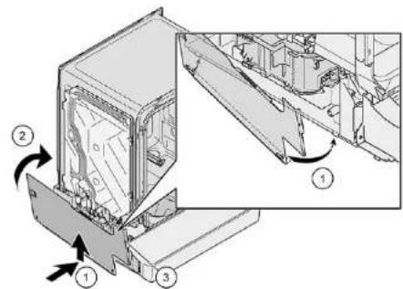
2. Press the side panel onto the upper edge (2). 3. Secure the side panel with the screws (3).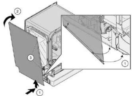

Repair
4.11 Adjusting the door
Adjustment:
The device excludes locking. The device excludes the supply line.
Mount in reverse order.

Repair
4.13 Fixing the spring-loaded door
1. Remove the cable from the door.
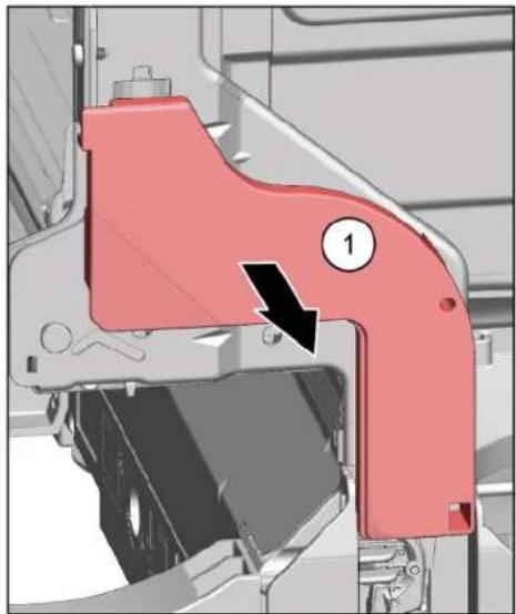
2.1. Open the door slightly (1).
2. Fix the spring in the hole of the base (2). 3. Close the door firmly (3).
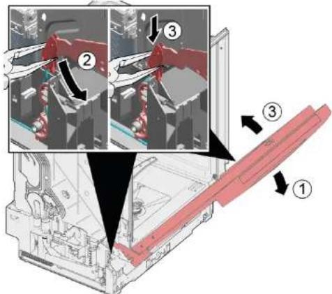
The cable system is automatically attached to the door.

Repair
3.1. Close the door slightly (4).
- Pull the lever back to release the door latch (5).
- Open the door (6).
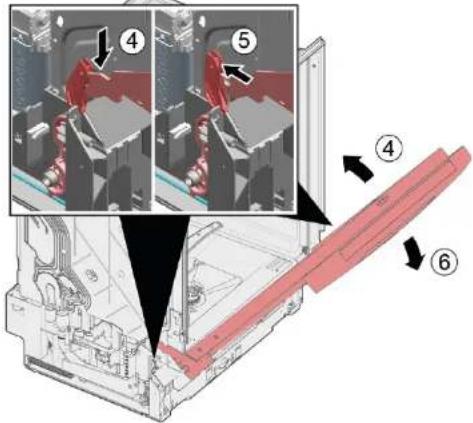
- Repeat the procedure on the other side of the device.
The cap can be replaced.
Inspection:
The cap is excluded from the fastening. The cap is excluded from the water supply network. The outer door is closed. The outer door is closed (with integrated hinge/hinge).
4.14.1 Fitting the bottom panel
1

Incorrect fitting. If the bottom panel is loose, loosen the screws, the two brackets can be opened. If only one bracket is damaged, the side can be replaced, as the brackets are threaded. It is recommended to place a new screw before the side, to secure the loading of the bottom panel with the cap.
2. Insert the guides (1) with the help of a screwdriver, turning clockwise.
- Bottom panel.
4. Pull the cap forward (1).
4.14.2 Mounting the bottom panel
- Place the cap.
- Attach the bottom panel to the side (1) and press it down, until it clicks into place (2).

Repair
4.15 Removing the main contact cover

The main contact cover is located on the front side.
The device is excluded from the warranty. The device is excluded from the warranty. The furniture panel (one-piece) is welded. The outer door is welded. The outer door is welded (optionally integrated/integrated). The lower panel is welded (one-piece).→26
4.15.1 Welding of the main contact
1. Weld the bolt (1).
2. Loosen the fastening elements (2).
- Carefully insert the main contact into the slot (1).
4.

Depending on the model, all parts are fastened to the base.
Loosen the part from the panel of the actuator and the tension spring (one-piece) (2).
4.15.2 Mounting of the main contact plug
Mount the plug of the main contact in the reverse order.

Repair
4.16 Replacement of the fuse

The fuse is located in the front lower part of the device.
Removal:
Disconnect the appliance from the power supply. Disconnect the appliance from the water supply. The furniture panel is removed (optional). The hinged door is removed. The furniture panel is removed (optional). →26 Refer to the installation instructions. →27
4.16.1 Draining the remaining water

Residual water
Depending on the installation, residual water may remain. The water must be drained into a suitable container.
- Release the door lock mechanism (1,2).
2. Loosen the fixing screws.

Repair
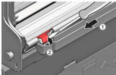
3.1. Insert the screwdriver into the slot (1). 2. Carefully release the metal clip (2)
- Disconnect the drain hose.
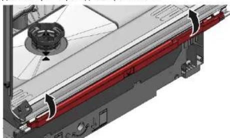
4.16.2 Connecting the drain hose

Danger of water damage due to incorrect installation of the drain hose!
Insert the drain hose into the drain pipe and secure it to the base.
4.23 Replacing the lamp (product lighting)
Requirement:
Disconnect the appliance from the power supply. Disconnect the appliance from the water supply. The hinged door is opened. The operating panel is removed.
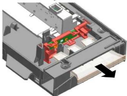
4.23.1 Removing the Gap illumination
1.1. Disconnect the connector (1).
2. Disconnect the electrical connection from the operating module (2).
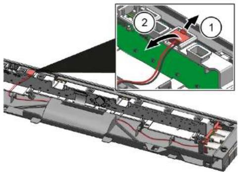
2.1. Disconnect the connector of the illuminator (1).
2. Disconnect the moistened (2).
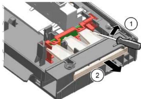

Repair
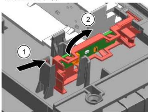
3.1. Disconnect the connector of the illuminator (1).
- Pull the printed circuit board out of the frame of the operating module (2).
4.23.2 Mounting the Gap illumination
- Place the board on the base plate in the frame of the operating module.
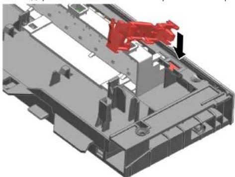
- Mount the optical moistened and tighten it, until you feel resistance.
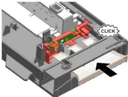
4. Connect the cable to the operating module.
4.23 Replacing the Gap illumination
Requirement:
4.22.1 Removing the timeLight 163 4.22.2 Mounting the timeLight 163
4.23 Replacing Gap illumination 164
4.23.1 Removing Gap illumination 164 4.23.2 Installing Gap illumination 165
4.21.2 Installing emotionLight
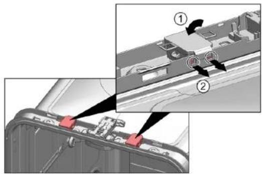
- Place the holder in the frame of the rinse tank (1).

Repair
- Activate the locking hook (2).
3.
NOTE
Incorrect installation!
4.22 Replacing timeLight

4.22.1 Removing timeLight
4.22.2 Installing timeLight
4.23 Replacing Gap illumination
Presetting:
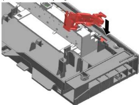
4.23.2 Installing Gap illumination
- Insert the printed circuit board holder into the frame of the operating module.
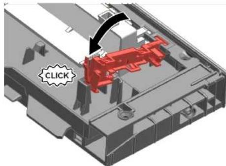
- Fasten it until it clicks into place.
2.1 General Safety Instructions
2.1.1 All Domestic Appliances
Tools and Aids.
Repair
4.1 Replacing Worktop
4.1.1 Removing Worktop 4.1.2 Installing Worktop
4.2 Installing Basket System
4.2.1 Installing a Tab Slide for the 86 cm Model 4.2.2 Installing Cup Support Clip 4.2.3 Installing Steamer Insert
4.3 Replacing VarioDrawer
4.3.1 Removing VarioDrawer 4.3.2 Installing VarioDrawer
4.4 Replacing Spray Arms
4.4.1 Removing Spray Arm 4.4.2 Installing Spray Arm
4.5 Replacing Filters
4.5.1 Removing filter 220 4.5.2 Installing filters 220
4.6 Installing baking sheet spray head 221
4.7 Replacing power cord 222
4.7.1 Unplugging power cord 222 4.7.2 Plugging in power cord 222
4.8 Replacing detergent cover 223
4.8.1 Removing detergent cover 223 4.8.2 Inserting spring 223 4.8.3 Installing detergent cover 223
4.9 Replacing wastewater pump cover 224
4.9.1 Removing wastewater pump cover 224 4.9.2 Installing wastewater pump cover 224
4.10 Replacing side panel 225
4.10.1 Removing side panel 225 4.10.2 Installing side panel 226
4.11 Replacing outer door 227
4.12 Replacing control panel 229
4.12.1 Removing control panel 229 4.12.2 Installing control panel 229
4.19 Replacing (lower) door seal 240
4.19.1 Removing the door seal 240 4.19.2 Installing the door seal 241
4.20 Replacing (upper) door seal
4.20.1 Removing door seal 242 4.20.2 Installing door seal 242
Repair hints - Dishwasher
4.21 Replacing EmotionLight
4.21.1 Removing EmotionLight 243 4.21.2 Installing EmotionLight 243
4.22 Replacing TimeLight
4.22.1 Removing TimeLight 246 4.22.2 Installing TimeLight 246
4.23 Replacing Gap illumination
4.23.1 Removing Gap illumination 247 4.23.2 Installing Gap illumination 248
Concerning this document
1.1 Important information
1.1.1 Purpose
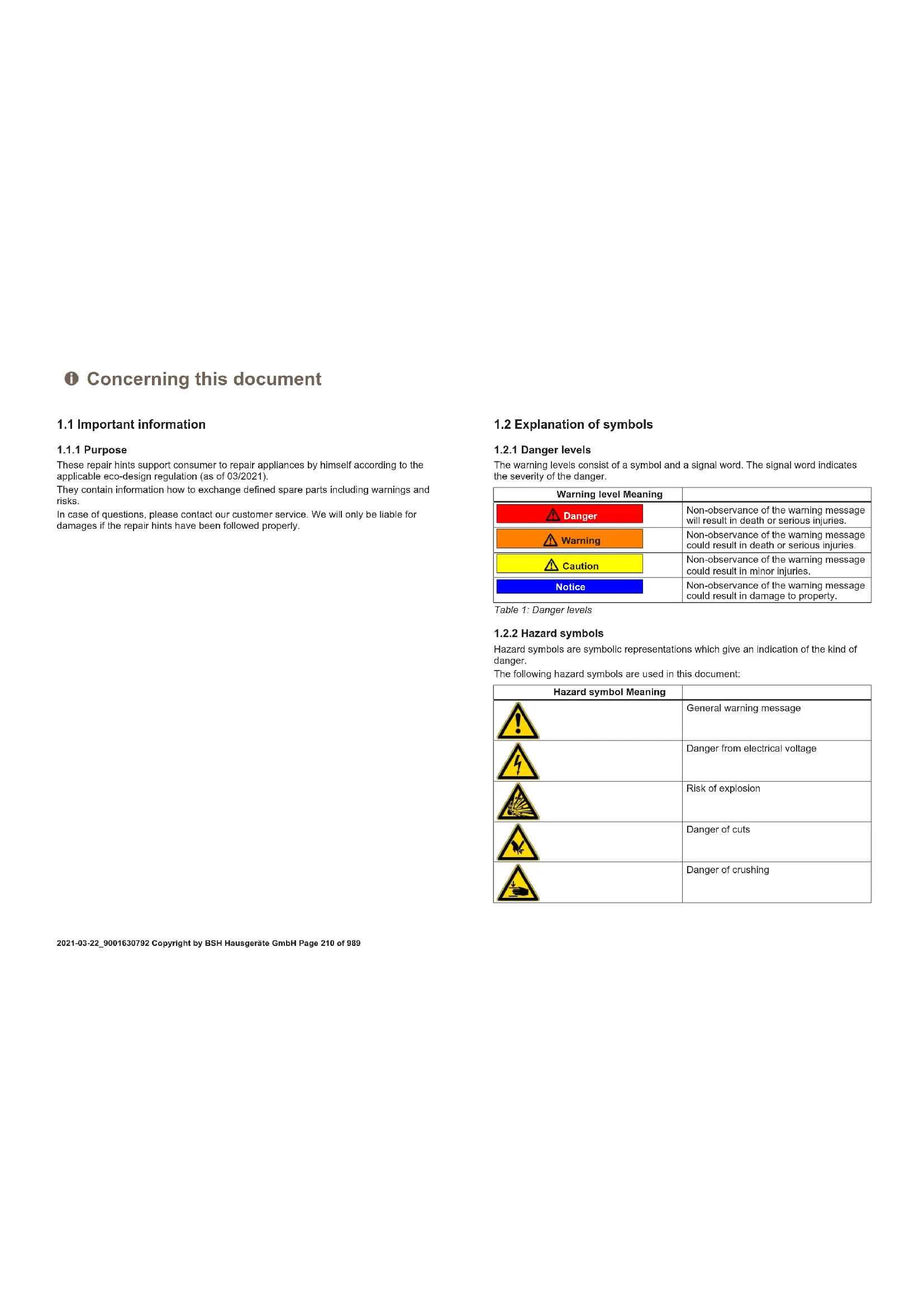
These repair hints support consumers to repair appliances by themselves according to the applicable eco-design regulation (as of 03/2021).
They contain information on how to exchange defined spare parts including warnings and risks.
In case of questions, please contact our customer service. We will only be liable for damages if the repair hints have been followed properly.
1.2 Explanation of symbols
1.2.1 Danger levels
The warning levels consist of a symbol and a signal word. The signal word indicates the severity of the danger.
Table 1: Danger levels
| Warning level Meaning | |
| Danger | Non-observation of the warning message will result in death or serious injuries. |
| Warning | Non-observation of the warning message could result in death or serious injuries. |
| Caution | Non-observation of the warning message could result in minor injuries. |
| Notice | Non-observation of the warning message could result in damage to property. |
1.2.2 Hazard symbols
Hazard symbols are symbolic representations which give an indication of the kind of danger.
The following hazard symbols are used in this document:
| Hazard symbol Meaning | |
| ! | General warning message |
| Danger from electrical voltage | |
| Risk of explosion | |
| Danger of cuts | |
| Danger of crushing |
Concerning this document
| Hazard symbol Meaning | |
| Danger from hot surfaces | |
| Danger from strong magnetic field | |
| Danger from non-ionizing radiation |
Table 2: Hazard symbols
1.2.3 Structure of the warnings
Warnings in this document have a standardised appearance and a standardised structure.
Danger
Type and source of danger!
Possible consequences of ignoring the danger / warning.
Measures and prohibitions for preventing the danger.
The following example shows a warning that warns against electric shock due to live parts. The measure for avoiding the danger is mentioned.

Danger
Risk of electric shock due to live parts!
Death by electrocution
- Disconnect appliances from electrical supply at least 60 seconds before starting repairs.
1.2.4 General symbols
The following general symbols are used in this document:
| Gen. symbol Meaning | |
| 1 | Identification of a special tip (text and/or graphic) |
| i | Identification of a simple tip (only text) |
| Identification of a link to a video tutorial |
| Gen. symbol Meaning | |
| Identification of required tools | |
| Identification of required preconditions | |
| Identification of a condition (if ..., then ...) | |
| Identification of a result | |
| [Start]Identification of a key or button | |
| [00123456] Identification of a material number | |
| Status Identification of displayed text / window(in the appliance's display) | |
Table 3: General symbols
Safety
2.1 General Safety instructions
2.1.1 All domestic appliances
Risk of electric shock due to live parts!
Errors by repairs involving electrical components can lead to electrical shock! - Disconnect the appliance from the mains for at least 60 seconds before starting work. After the repair have a safety test according VDE 0701 or country-specific regulations performed.
Risk of injury from sharp edges!
Wear protective gloves.
Risk of crushing during repair, maintenance, troubleshooting and service due to heavy and moving components
Wear protective shoes. - Secure heavy components from falling down. - Do not stick body parts into moving components.
Risk to the appliance's safety / function! Only use original spare parts. Risk of damage to electrostatically sensitive components (ESDs)! - Do not touch the modules, including connections and conductor paths.

Tools and aids
| Designation Details Images | ||
| Screwdriver Torx T20 with bore hole [00340764] | 100 mm, for screws with safety pin | |
| Insulated Screw- driver Torx T15 with bore hole [15000626] | Blade length 125 mm, for screws with safety pin | |
| Slotted screwdriver | Blade 10 mm x 1.6 mm x 200 mm | |
| Needle nose pliers [00340871] | Length: 200 mm, straight | |
4.1 Replacing worktop
Prerequisite:
Appliance is disconnected from the power supply. Appliance is freely accessible.
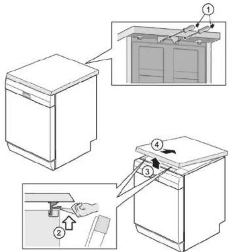
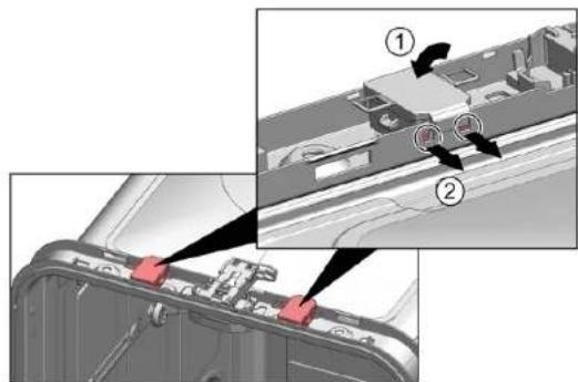
4.1.1 Removing worktop
- Remove the two screws at the back (1) (optional).
- Press both catch levers under the worktop upwards (2).
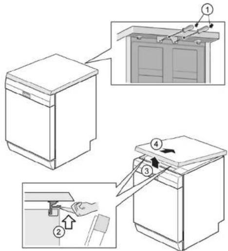
- Lift the worktop slightly at the front (3).
- Push worktop away towards the rear (4).
- Remove worktop.
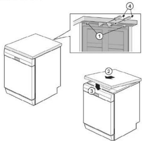
4.1.2 Installing worktop
- Lock the rear of the worktop into the guides using the retaining collars (1).
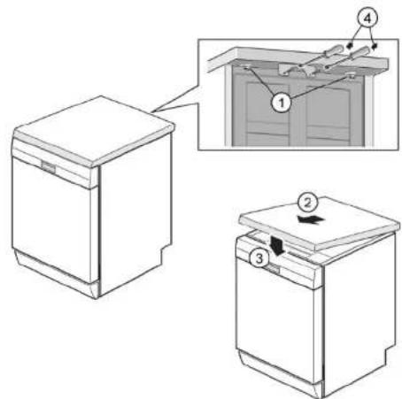
- Push worktop forwards (2).
- Press the front of the worktop downwards until both catch levers click audibly into place (3).
- Screw in the two screws again (4) (optional).

Repair
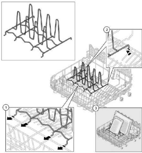
4.2 Installing basket system
Prerequisite:
The relevant basket has been removed from the appliance.
4.2.1 Installing a tab slide for the 86 cm model
Required tools:
Tabguide [00614935] Cup support clip [00618565]
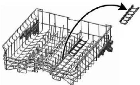
- Insert the tab slide diagonally at the front of the basket.
- Centre and click the tab chute into place.
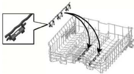
4.2.2 Installing cup support clip
Required tools:
Tabguide [00614935] Cup support clip [00618565]

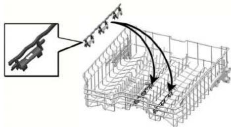
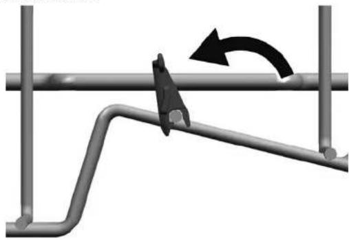
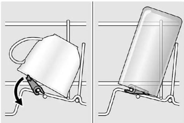
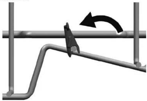
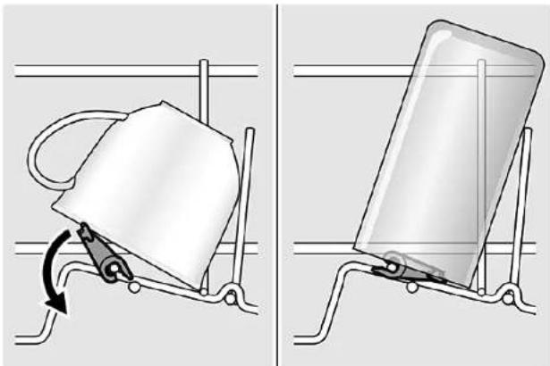
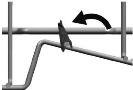
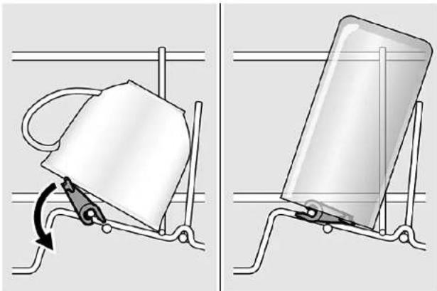
When washing cups, the cup support clip can be folded up. The additional angle reduces the collection of water on the bottom of cups. In the case of tall glasses we recommended leaving the cup support clip folded down. If upper baskets have an optional plastic insert, they must first be removed.
- Remove the plastic insert.
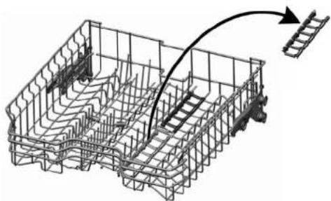
- Click the cup support clip into place.
- Fold up the clip.

Repair
- Position the items to be washed.
4.2.3 Installing steamer insert
Required tools:
Tabguide [00614935] Cup support clip [00618565]
- Wedge the steamer insert with the end pieces under the basket system.
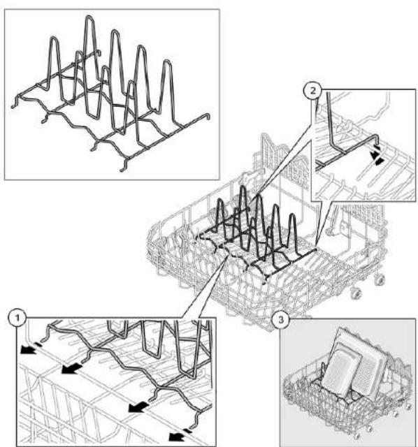

Repair
4.3 Replacing varioDrawer
4.3.1 Removing varioDrawer
- Bend the handle flaps inwards.
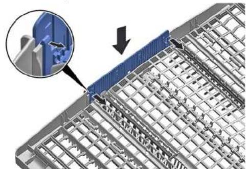
- Remove the handle upwards.
- Press the plastic side inserts outwards and push them upwards out of the frame.
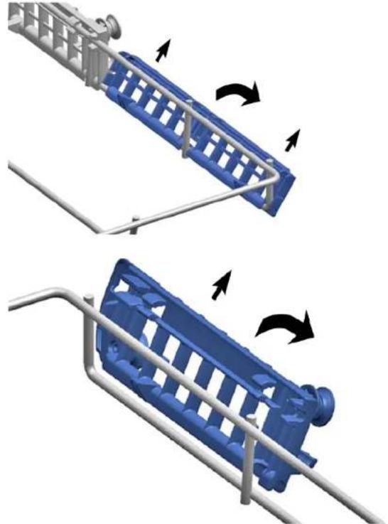

Repair
- Carefully bend the guide tabs outwards.
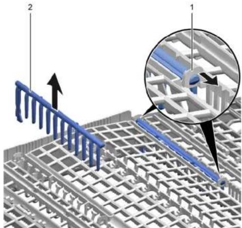
- Pull the folding spines out of the tabs.
- Press the metal frame at the front out of the holders.
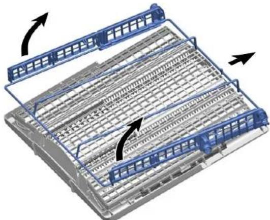
- Push the metal frame back out of the guide.
4.3.2 Installing varioDrawer
Install in reverse order.

Repair
4.4 Replacing spray arms
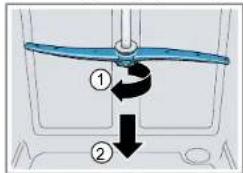
4.4.1 Removing spray arm
- Unscrew the upper spray arm (1) and pull down to remove (2).
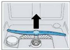
- Pull down the lower spray arm to remove.
4.4.2 Installing spray arm
- Insert the lower spray arm. The spray arm clicks into position.
- Insert the upper spray arm and screw it firmly in place.

Repair
4.5 Replacing filters
4.5.1 Removing filter
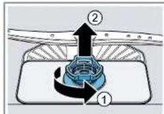
- Turn the coarse filter anticlockwise (1) and remove the filter system (2).
Check that no foreign objects fall into the sump.
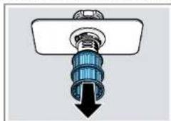
- Pull down the micro filter to remove.
4.5.2 Installing filters
- Re-assemble the filter system. Make sure that the locking catches on the coarse filter click into position.
- Insert the filter system into the appliance and turn the coarse filter clockwise. Make sure that the arrow markings match up.

Repair
4.6 Installing baking sheet spray head
- Remove top basket.
- Insert the baking sheet spray head in the holder (1) and turn to the right (2).
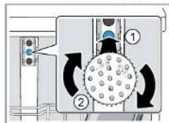

The baking sheet spray head clicks into position.

Repair
4.7 Replacing power cord
Prerequisite:
Appliance is disconnected from power supply. Appliance is disconnected from water supply. Appliance is freely accessible.
4.7.1 Unplugging power cord
- Move the plug of the power cord carefully up and down and pull it out of the mains socket.
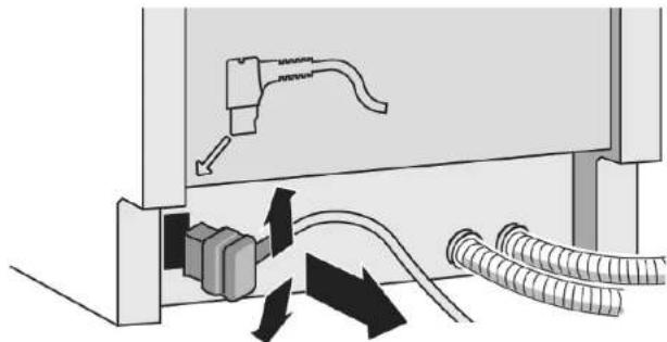
4.7.2 Plugging in power cord

Notice
Overheating of main connection!
Risk of fire
Firmly insert the power cord until it clicks.
- Insert the plug of the power cord into the mains socket until the plug clicks audibly into place.
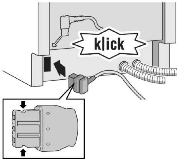

Repair
4.8 Replacing detergent cover

A small screwdriver can be used as a levering tool.
Prerequisite:
The appliance is disconnected from the power supply. The appliance is disconnected from the water supply. The door has been opened. The detergent cover has been opened.
4.8.1 Removing detergent cover
- Slide the detergent cover in 5 mm.
- Lever the detergent cover on the lower side out of the guide rails and take the detergent cover on the upper side out of the guide rails.
- Remove the spring.
4.8.2 Inserting spring
- Insert the long end of the spring into the mounting hole of the dispenser device (1).
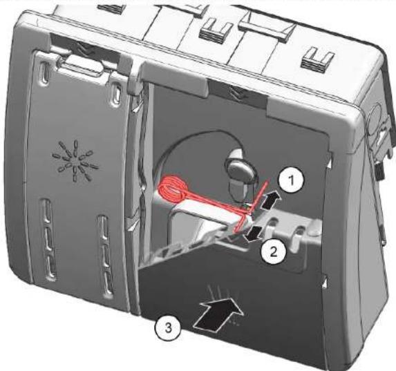
- Insert the short end of the spring into the mounting hole of the detergent cover (2).
- Press the cover into the dispenser device (3).
4.8.3 Installing detergent cover
- Insert the detergent cover 5 mm before the completely open position into the guide rails on one side. Applying gentle force, press the opposite side into the guide rails.
- Check the function of the detergent cover.

Repair
4.9 Replacing wastewater pump cover
Prerequisite:
Basket has been removed. Filters have been removed. -> Page 220
4.9.1 Removing wastewater pump cover
- Scoop out any water.
Use a sponge if necessary.
- Pry off the pump cover using a spoon and grip it by the crosspiece.
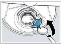
- Lift the pump cover inwards at an angle and remove.
4.9.2 Installing wastewater pump cover
Insert the pump cover (1) and press down (2).
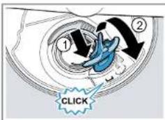
The pump cover clicks into position.

Repair
4.10 Replacing side panel
Prerequisite:
The appliance is disconnected from the power supply. The appliance is disconnected from the water supply. The appliance is freely accessible. For free-standing appliances: The worktop has been removed. See page 214.
4.10.1 Removing side panel
- Remove the screws from the side panel (1).
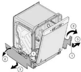
Fig. 1: Fully integrated
- Tilt the side panel slightly outwards at the top (2).
- Lower the side panel and pull it out of the base trough (3).

Repair
4.10.2 Installing side panel
- Insert the side panel into the base trough (1).
Fig. 2: Fully integrated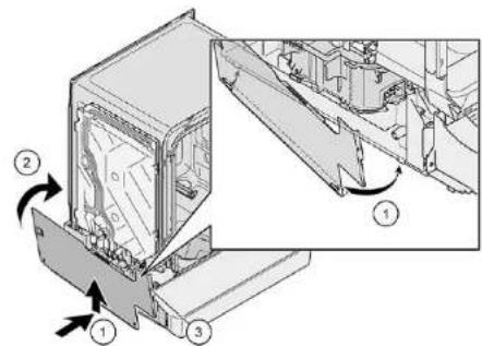
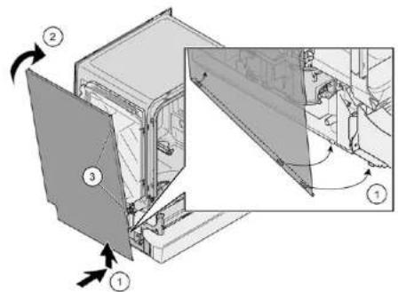
- Press the side panel onto the appliance (2).
- Secure the side panel with screws (3).

Repair
4.11 Replacing outer door
Prerequisite:
The appliance is disconnected from the power supply. The appliance is disconnected from the water supply.
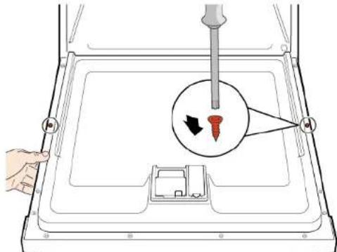
Just remove the screws which are described in the following steps.
- Open door.
- Remove four screws.
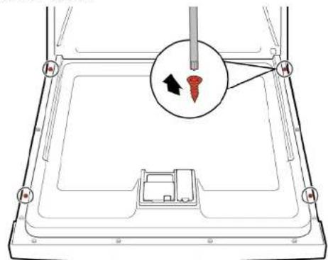
3

Secure the door by holding it on one side.
Remove two screws.
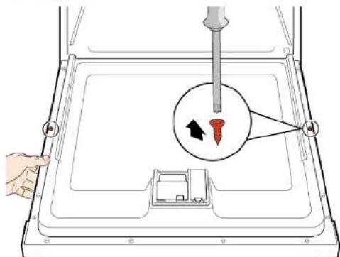
Insulating fleece has been correctly positioned and fixed on the inside of the outer door. Hinges are inserted into the outer door.
- Close the inner door without snapping it shut.
- Push the outer door upwards underneath the control panel (1).
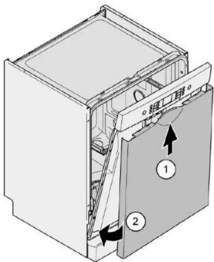
- Press the outer door against the inner door and hold (2).
4.

Secure the door by holding it on one side.
Open the door and secure it with two screws (4 x 11 mm metal screws).
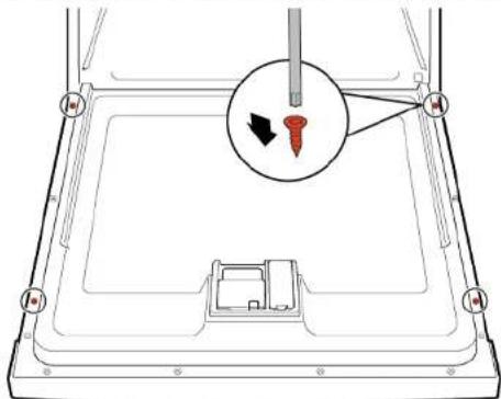
- Secure the outer door with four screws (4 x 11 mm metal screws).

Repair
4.12 Replacing control panel

If an operating module is defective, the entire control panel must be replaced.
Prerequisite:
Appliance is disconnected from power supply. Appliance is disconnected from water supply. Outer door has been removed. Outer door has been removed (fully integrated/integrated).
4.12.1 Removing control panel
- Disconnect electrical connections from the control panel and the low rinse-aid sensor (1, 2).
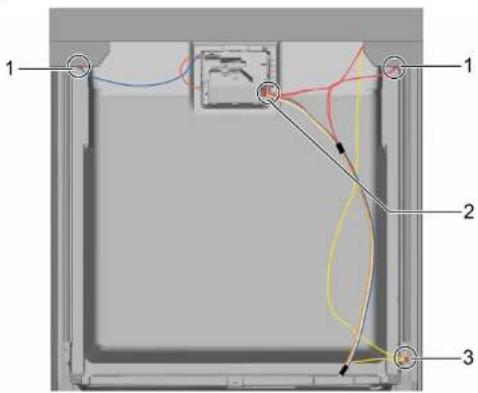
- Disconnect the earth cable (3) (optional).
- Open the appliance door.
- Secure the control panel to prevent it from falling down (hold on to it).
- Remove six screws.
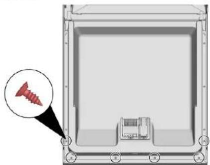
- Remove the control panel.
4.12.2 Installing control panel

Use screws 4 × 16 mm .
Install in reverse order.

Repair
- Remove cord guide cover out.

2.1. Open door slightly (1).
- Fix in the groove of the base trough (2).
- Slowly close the door (3).
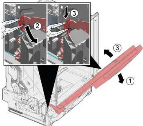
The cord system attaches itself automatically to the door hinge.

Repair
3.1. Slightly close the door (4).
- Move the groove to the back and release the door hinge (5).
- Open the door (6).
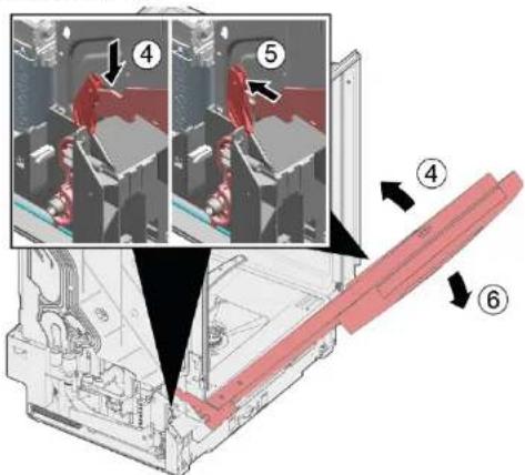
- Repeat the process on the other side of the appliance.

Repair
4.14 Replacing the toe panel

The feet are identical and can be swapped over.
Prerequisite:
The appliance is disconnected from the power supply. The appliance is disconnected from the water supply. The outer door has been removed. The outer door has been removed (fully integrated/integrated).
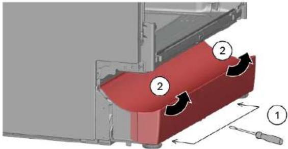
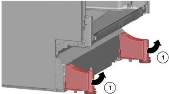
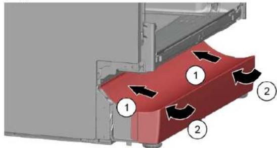
4.14.1 Removing the toe panel
1.

Incorrect removal. If the toe panel is loosened at the side and removed, the two brackets may break away. If only one bracket is damaged, the side can be changed as the brackets are identical. It is advisable to place something under the appliance at the front on the side to relieve the load on the toe panel with the feet.
- Reach into the guides (1) with a screwdriver and release the catch by pushing downwards.
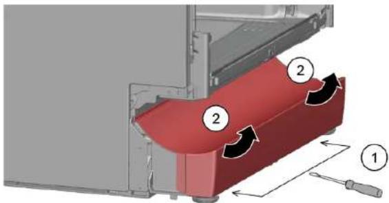
- Lift the panel off.
- Remove the feet forwards (1).
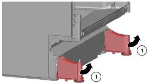
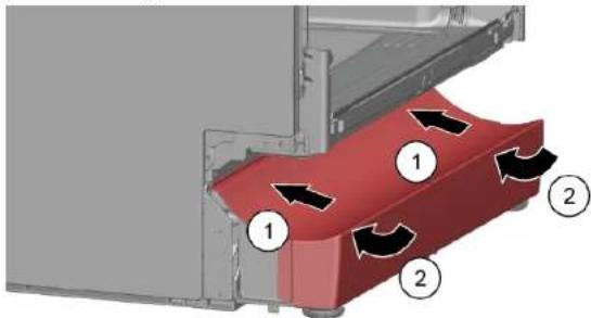
4.14.2 Installing toe panel
- Insert the feet.
- Attach the toe panel at the top (1) and press it down until it audibly clicks into place (2).

Repair
4.15 Replacing base socket plate

The base socket plate is located in the lower area at the front.
Prerequisite:
Appliance is disconnected from power supply. Appliance is disconnected from water supply. Furniture panel (optional) has been removed. Outer door has been removed. Outer door has been removed (fully integrated/integrated). Toe panel has been removed (optional). See page 232.
4.15.1 Removing base socket plate
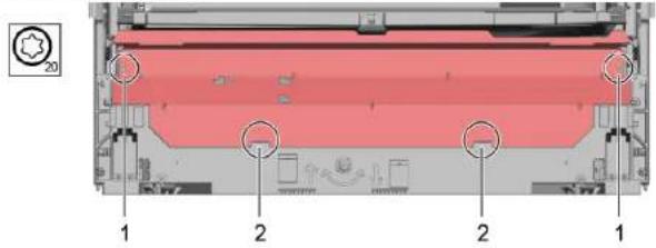
- Remove two screws (1).
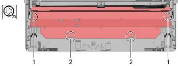
- Disengage catch elements (2).
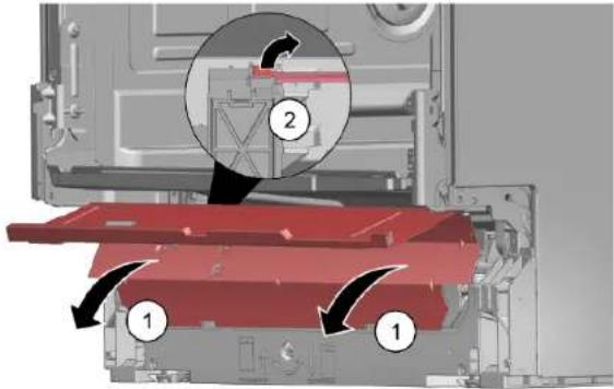
- Tilt the base socket plate carefully forwards (1).
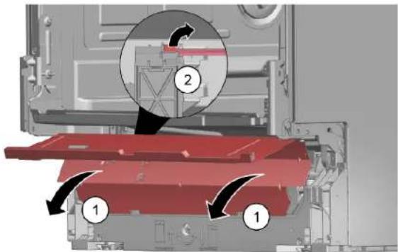
4.

Depending on the model series, the plug to the EmotionLight is still secured to the base.
Unlock the plug on the catch tappet and pull to the rear (optional) (2).
4.15.2 Installing base socket plate
Install the base socket plate in reverse order.

Repair
4.16 Replacing overflow conduit

The overflow conduit is located in the front lower area of the appliance.
Prerequisite:
Appliance is disconnected from power supply. Appliance is disconnected from water supply. Furniture panel has been removed (optional). Outer door has been removed. Toe panel has been removed (optional). See page 232. Base socket plate has been removed. See page 233.
4.16.1 Removing overflow channel

Residual water
- When the drainage hose is removed, residual water may run out. Catch water or remove from the base pan with suction syringe.
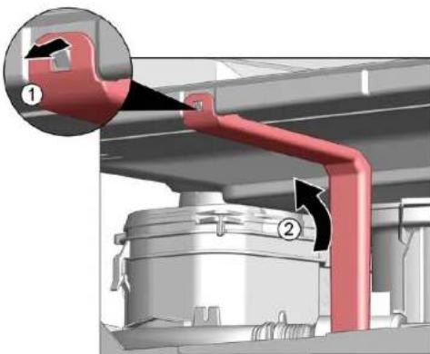
- Lever out of the catch mechanism at the top (1, 2).
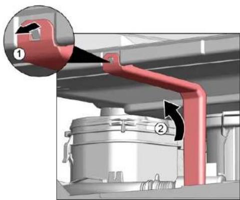
- Release catch element at top.
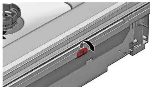
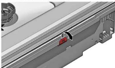
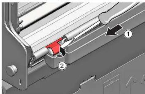
3.1. Insert screwdriver below metal brake (1).
- Gently release metal clip (2).

Repair
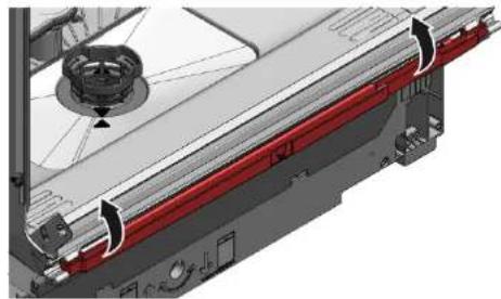
- Lift overflow conduit off.
4.16.2 Installing overflow conduit

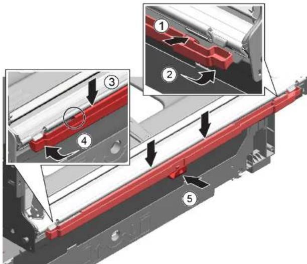
Water damage due to incorrect installation of the overflow conduit! Correctly insert the overflow conduit at the bottom into the guide of the base trough. Click the overflow conduit correctly into place at the top.
- Place overflow conduit (1).
- Move overflow conduit into seal (2).
- Press overflow conduit in guide of seal (3).
- Insert overflow conduit concisely (4).
- Clip in overflow conduit (5).

Repair
- Check installation left and right. 3. Check firm seat.
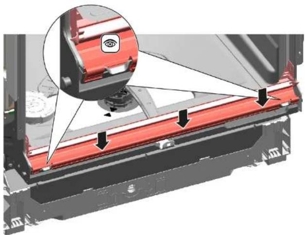
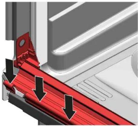
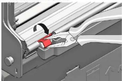
- Clip in metal clip on left and right side.

Repair
4.17 Replacing inner door
Prerequisite:
Appliance is disconnected from power supply. Appliance is disconnected from water supply.
4.17.1 Removing inner door
- Remove screws (1).
- Remove inner door upwards (2).
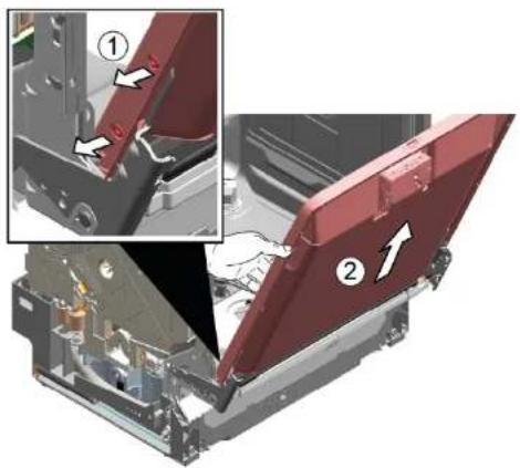
4.17.2 Installing inner door
- Flap door seal to front.
- Move inner door behind door seal.
- Close inner door.
- Flap door seal upwards. Sideparts show up
- Move door hinge upwards.
- Secure door hinge with screws.
- Place inner door on door hinge.
- Secure inner door with screws.

Repair
4.18 Replacing door hinge
Prerequisite:
Appliance is disconnected from power supply. Appliance is disconnected from water supply. Appliance is freely accessible. Side panel has been removed. (see page 225) Outer door has been removed. Inner door has been removed. Control panel has been removed. (see page 229) Door springs have been fixed. (see page 230) Toe panel has been removed. (see page 232) Base socket plate has been removed. (see page 233) Overflow channel has been removed. (see page 234)
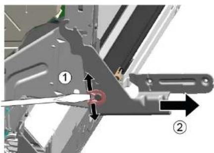
- Release catch hook with a screwdriver (1).
- Pull door hinge forwards (2).
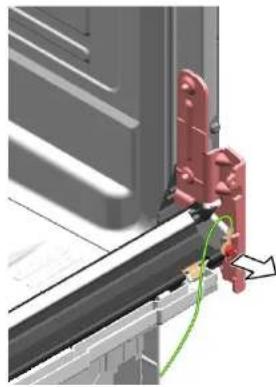
- Release ground connection on door hinge.
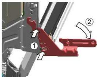
- Place hinge on appliance (1).
- Move hinge downwards (2) till it is latched to the appliance.
2.

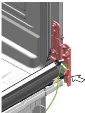
A missing ground connection can lead to mains potential on door.
Establish ground connection.
4.19 Replacing (lower) door seal
Prerequisite:
Appliance is disconnected from power supply. Appliance is disconnected from water supply. Outer door has been removed. Base socket plate has been removed. (See page 233) Toe panel has been removed (optional). (See page 232) Door springs have been removed. Control panel has been removed. Cable harness holder on bottom right has been removed.
4.19.1 Removing the door seal
- Remove the two retaining clips on the lower door seal (1, 2).
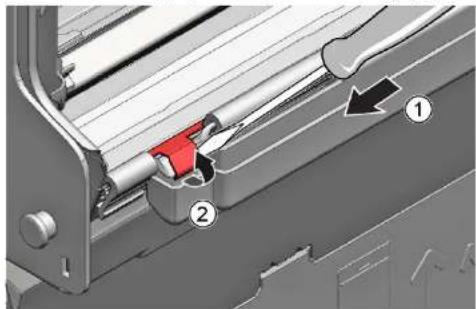
- Detach the overflow channel.
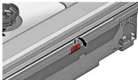
- Lift the overflow gutter off.
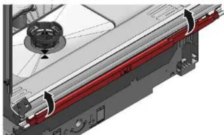

Repair
- Remove the lower door seal from the inner door.
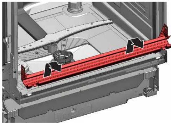
4.19.2 Installing the door seal
- Fit the sealing caps on the left and right to the sealing rail with the door seal.
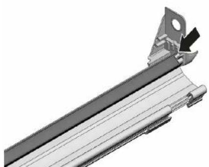
- Insert the door seal with the sealing flap in the inner door.
- Secure the door seal with two retaining clips.

Repair
4.20 Replacing (upper) door seal
Prerequisite:
Appliance is disconnected from power supply. Appliance is disconnected from water supply.
4.20.1 Removing door seal
- Remove door seal from inner frame.
4.20.2 Installing door seal
The door seal must be cut to the correct length before installation. This is 1750 mm for appliances of 81 cm in height and 1850 mm for appliances of 86 cm in height.
- Prepare appropriate door seal.
- Ensure correct installation position of sealing profile.
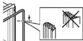
- White dot must be on level with sealing bed strip.
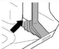
4

Sealing must not be wavy or stretched at corners. Seal is cut off diagonally at ends and tapers away into bottom of container at front.
Position end of seal straight to front underneath inner door. Seal should lie against side of container as far as possible.

Correctly installed door seal:
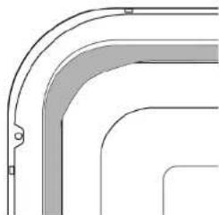

Repair
4.21 Replacing EmotionLight

The EmotionLight is situated in the upper front exterior area of the rinsing tank.
Prerequisite:
Appliance is disconnected from power supply. Appliance is disconnected from water supply. Appliance is freely accessible. Worktop has been removed (optional). The right-hand side panel has been removed (optional). See page 225
4.21.1 Removing EmotionLight
- Detach catch hook at the rear (1).
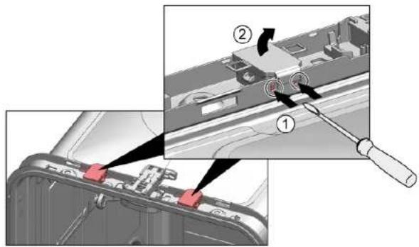
- Remove the holder upwards (2).
- Pull plug out of connector (bottom right at front of appliance).
- Remove electrical connection from the power module.
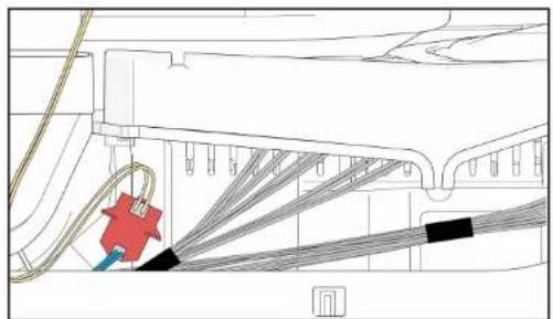
- Remove EmotionLight from the appliance.
4.21.2 Installing EmotionLight
- Insert the holder into the rinsing tank frame (1).
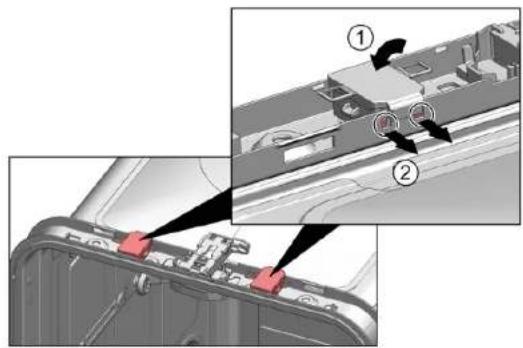

Repair
- Engage the catch hook (2).
3
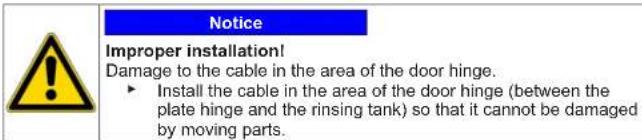
Install the cable on the right lower side.
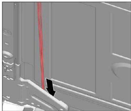

Repair
Fig. 3: Flat cable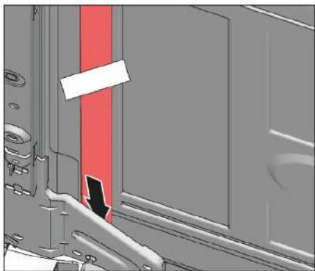
- Insert the plug.

Repair
4.22 Replacing TimeLight

Replace the TimeLight only as a complete part. The TimeLight module is fixed to the rear of the base socket plate.
Prerequisite:
Appliance is disconnected from power supply. Appliance is disconnected from water supply. Toe panel has been removed. -> Page 232 Base socket plate has been removed and turned. -> Page 233
4.22.1 Removing TimeLight
- Bend the catch elements (1) slightly outwards.
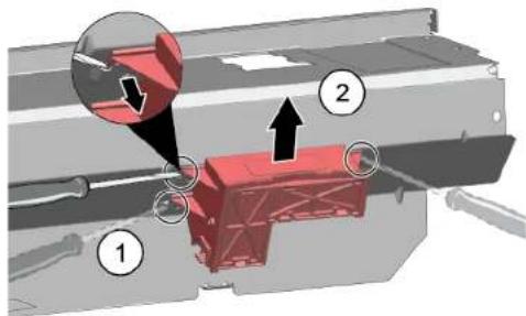
- Pull the TimeLight module upwards out of the guide (2).
4.22.2 Installing TimeLight
- Bend the catch elements (1) back again.
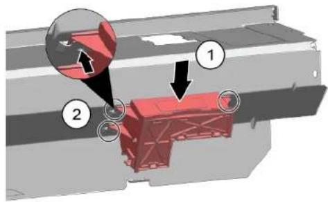
- Push the TimeLight module into the guide (2).
- Connect the electrical connection.

Repair
4.23 Replacing Gap illumination
Prerequisite:
Appliance is disconnected from power supply. Appliance is disconnected from water supply. Outer door is disassembled. Operation panel has been removed.
4.23.1 Removing Gap illumination
- Detach catch (1).
- Remove electrical connection from the operation module (2).
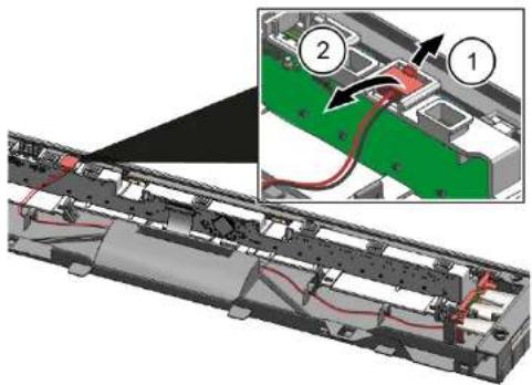
- Detach catch hook at rear (1).
- Remove light fibre (2).

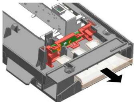

Repair
3.1.Detach catch hook (1).
- Lift up PCB with holder and remove it from operation module frame (2).
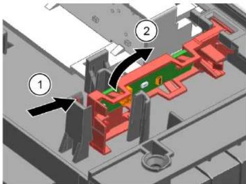
4.23.2 Installing Gap illumination
- Insert PCB holder to operation module frame.
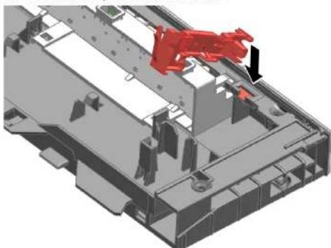
- Tighten it with a "click" sound.
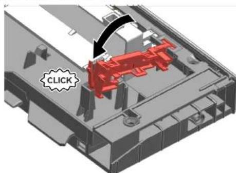
- Install light fibre and tighten it with a "click" sound.
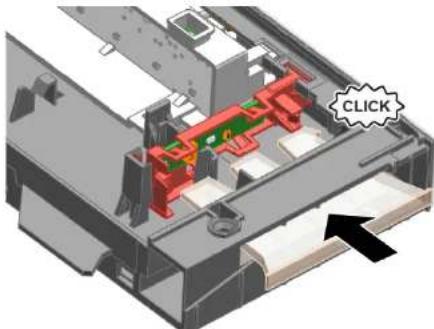
- Connect wire to operation module.
Regarding this document 251
1.1 Important information 251
1.1.1 Purpose 251 1.2 Explanation of symbols 251 1.2.1 Safety 251 1.2.2 Warning symbols 251 1.2.3 Structure of warnings 252 1.2.4 General symbols 252
Safety 253
2.1 General safety instructions 253 2.1.1 All household appliances 253
Table 1: Safety devices
1.2.2 Warning symbols
3. Open the device to check.
- TOnToeTeHToTe Ta AvtiKeIeVv ia TAnoIpo
4.2.3 ToTToeTeTOn eVeTeou atOpayEipa EIOKα Bontntika μεσα:
∑upóevnθηkn taμπλετac [00614935] KAIITOrnpiEgPAnCavw[00618565] - 2pynwote To EvTeo atmuayepa Te ta kpa KAToTo ouTnka KaalaiiWv.

EMIOKEUN
4.3 Replacing the battery drawer
- Isimkite, EmotionLight" is a device.
4.2.1.2 Installing "EmotionLight"
- [Mounting bracket] rinse tank holder (1).

Repair
2. Secure with the mounting lock (2).
3
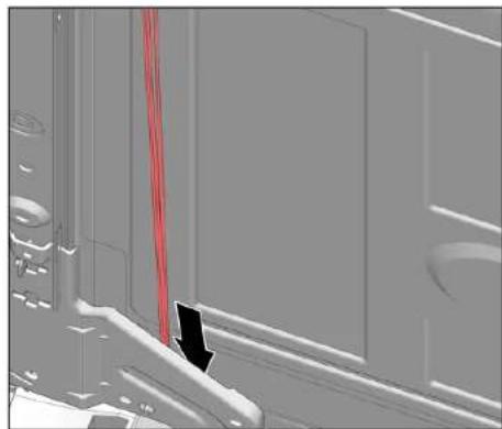
CAUTION!
Incorrect installation!
The door cable may be damaged in the hinge area.
Connect the cable in the door hinge area (between the hinge bracket and the rinse tank) so that moving parts do not damage it.
Connect the cable to the left lower side.

Repair
Fig. 3: Flat cable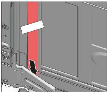
- Insert the plug
2021-03-22_9001630792 Copyright BSH Hausgerate GmbH Page 616 of 989

Repair
4.22 Replacing the TimeLight

4.23.2 Installing the Gap illumination
4.17.1 Removing the interior door 731 4.17.2 Installing the interior door 731
4.18 Replacing the door hinge 732
4.18.1 Removing the door hinge 732 4.18.2 Installing the door hinge 732
4.19 Replacing the door seal (lower) 734
4.19.1 Removing the door seal 734 4.19.2 Installing the door seal 735
4.20 Replacing the door seal (upper) 736
4.20.1 Removing the door seal 736 4.20.2 Installing the door seal 736
Troubleshooting tips - Dishwasher
4.21 Replacing the EmotionLight 737
4.21.1 Removing the EmotionLight 737 4.21.2 Installing the EmotionLight 737
4.22 Replacing the TimeLight 740
4.22.1 Removing the TimeLight 740 4.22.2 Installing the TimeLight 740
4.23 Replacing the Gap Illumination 741
4.23.1 Remove a Gap Illumination 741 4.23.2 Install a Gap Illumination 742
4.17.1 Remove the interior door
4.17.2 Install the interior door
4.23.1 Remove a Gap Illumination
- Release the catch (1).
- Disconnect the electrical connection of the operating module (2).
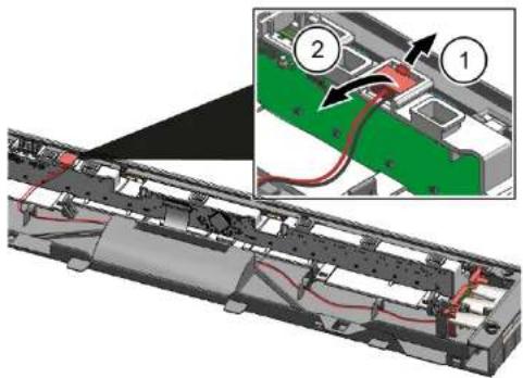
2.1. Release the rear catch (1). 2. Remove the optical fiber (2).
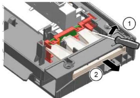
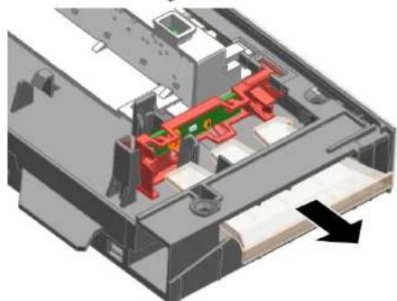

Repair
3. 1. Release the catch (1).
4.23 Replace Gap illumination 823
4.23.1 Remove Gap illumination 823 4.23.2 Install Gap illumination 824
About this document
4.23 Replace Gap illumination
Requirement:
4.23 Replacing the gap illumination
Prerequisite:
The device is disconnected from the power supply. The device is disconnected from the water supply. The outer door has been removed. The control panel has been removed.
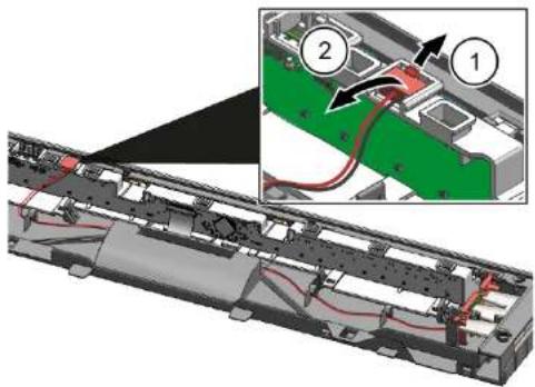
4.23.1 Removing the gap illumination
- Release the latch (1).
- Disconnect the electrical connection from the control module (2).
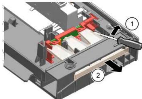
2.1. Release the hook at the rear (1).
- Remove the optical fiber (2).
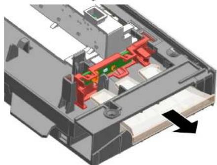

Repair
3.1. Release the hook (1).
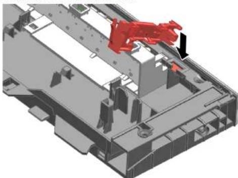
4.23.2 Installing the gap illumination
- Insert the circuit board into the frame of the control module.
Tab Guide [00614935] Snap-in part [00618565]

- REPAIR TIPS - DIY MACHINE
- ABOUT THIS DOCUMENT
- IMPORTANT INFORMATION
- GENERAL
- EXPLANATION OF SYMBOLS
- HAZARD
- HAZARD SYMBOLS
- REGARDING THIS DOCUMENT
- STRUCTURE OF WARNINGS
- DANGER
- GENERAL SYMBOLS
- SAFETY
- GENERAL SAFETY INSTRUCTIONS
- ALL HOUSEHOLD APPLIANCES
- TOOLS AND AIDS
- REPAIR
- WORK SAFETY
- WORK SAFETY INSTRUCTIONS
- MOUNTING ON THE WORK AREA
- MOUNTING THE CONE SYSTEM
- MOUNTING THE CONE GUIDE FOR THE 86-CM MODEL
- MOUNTING THE LOCKING MECHANISM
- MOUNTING OF THE BLOCK OF THE VAPORIZER
- MOUNTING OF THE SIDE PANEL
- ADJUSTING THE DOOR
- FIXING THE SPRING-LOADED DOOR
- INSPECTION
- FITTING THE BOTTOM PANEL
- MOUNTING THE BOTTOM PANEL
- REMOVING THE MAIN CONTACT COVER
- WELDING OF THE MAIN CONTACT
- MOUNTING OF THE MAIN CONTACT PLUG
- REPLACEMENT OF THE FUSE
- REMOVAL
- DRAINING THE REMAINING WATER
- RESIDUAL WATER
- CONNECTING THE DRAIN HOSE
- REPLACING THE LAMP (PRODUCT LIGHTING)
- REMOVING THE GAP ILLUMINATION
- DISCONNECT THE CONNECTOR OF THE ILLUMINATOR (1)
- MOUNTING THE GAP ILLUMINATION
- REPLACING THE GAP ILLUMINATION
- INSTALLING EMOTIONLIGHT
- NOTE
- INCORRECT INSTALLATION
- REPLACING TIMELIGHT
- REMOVING TIMELIGHT
- INSTALLING TIMELIGHT
- REPLACING GAP ILLUMINATION
- INSTALLING GAP ILLUMINATION
- REPAIR HINTS - DISHWASHER
- CONCERNING THIS DOCUMENT
- PURPOSE
- DANGER LEVELS
- STRUCTURE OF THE WARNINGS
- ALL DOMESTIC APPLIANCES
- REPLACING WORKTOP
- REMOVING WORKTOP
- INSTALLING WORKTOP
- INSTALLING BASKET SYSTEM
- INSTALLING A TAB SLIDE FOR THE 86 CM MODEL
- INSTALLING CUP SUPPORT CLIP
- INSTALLING STEAMER INSERT
- REPLACING VARIODRAWER
- REMOVING VARIODRAWER
- INSTALLING VARIODRAWER
- REPLACING SPRAY ARMS
- REMOVING SPRAY ARM
- INSTALLING SPRAY ARM
- REPLACING FILTERS
- REMOVING FILTER
- INSTALLING FILTERS
- INSTALLING BAKING SHEET SPRAY HEAD
- REPLACING POWER CORD
- UNPLUGGING POWER CORD
- PLUGGING IN POWER CORD
- NOTICE
- REPLACING DETERGENT COVER
- PREREQUISITE
- REMOVING DETERGENT COVER
- INSERTING SPRING
- INSTALLING DETERGENT COVER
- REPLACING WASTEWATER PUMP COVER
- REMOVING WASTEWATER PUMP COVER
- INSTALLING WASTEWATER PUMP COVER
- REPLACING SIDE PANEL
- REMOVING SIDE PANEL
- INSTALLING SIDE PANEL
- REPLACING OUTER DOOR
- REPLACING CONTROL PANEL
- REMOVING CONTROL PANEL
- INSTALLING CONTROL PANEL
- REPLACING THE TOE PANEL
- REMOVING THE TOE PANEL
- INSTALLING TOE PANEL
- REPLACING BASE SOCKET PLATE
- REMOVING BASE SOCKET PLATE
- INSTALLING BASE SOCKET PLATE
- REPLACING OVERFLOW CONDUIT
- REMOVING OVERFLOW CHANNEL
- INSTALLING OVERFLOW CONDUIT
- REPLACING INNER DOOR
- REMOVING INNER DOOR
- INSTALLING INNER DOOR
- REPLACING DOOR HINGE
- REPLACING (LOWER) DOOR SEAL
- REMOVING THE DOOR SEAL
- INSTALLING THE DOOR SEAL
- REPLACING (UPPER) DOOR SEAL
- REMOVING DOOR SEAL
- INSTALLING DOOR SEAL
- REPLACING EMOTIONLIGHT
- REMOVING EMOTIONLIGHT
- REMOVING GAP ILLUMINATION
- DETACH CATCH HOOK (1)
- WARNING SYMBOLS
- TOTTOETETON EVETEOU ATOPAYEIPA EIOKΑ BONTNTIKA ΜΕΣΑ
- EMIOKEUN
- REPLACING THE BATTERY DRAWER
- INSTALLING "EMOTIONLIGHT
- CAUTION
- REPLACING THE TIMELIGHT
- INSTALLING THE GAP ILLUMINATION
- TROUBLESHOOTING TIPS - DISHWASHER
- REMOVE THE INTERIOR DOOR
- INSTALL THE INTERIOR DOOR
- REMOVE A GAP ILLUMINATION
- RELEASE THE CATCH (1)
- REPLACE GAP ILLUMINATION
- RELEASE THE HOOK (1)
Brand : BOSCH
Model : SMI8YBS01D
Category : Dishwasher