USER MANUAL WS5200 ALECTO
Tabel 1: Snelstartgids
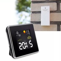
Thank you for your purchase of the Wireless Wi-Fi Weather Station, which is designed with the latest low power Wi-Fi technology. Both the indoor and outdoor unit requires 2pcs Lithium AA batteries to operate. The following user guide provides step by step instructions for installation, operation and troubleshooting.
1Warnings and Cautions
Warning: Any metal object may attract a lightning strike, including your weather station mounting pole. Never install the weather station in a storm.
Warning: Installing your weather station in a high location may result in injury or death. Perform as much of the initial check and operation on the ground and inside a building or home. Only install the weather station on a clear, dry day.
2 Quick Start Guide
Although the manual is comprehensive, much of the information contained may be intuitive. In addition, the manual does not flow properly because the sections are organized by components.
The following Quick Start Guide provides only the necessary steps to install, operate the weather station, and upload to the internet, along with references to the pertinent sections.
Table 1: Quick Start Guide
| Required |
| Step | Description | Section | Page |
| 1 | Content | 5.1 | 4 |
| 2 | Sensor array set up | 5.2 | 4 |
| 3 | Install mounting pole | 5.2.1 | 5 |
| 4 | Install outdoor unit | 5.2.2 – 5.2.7 | 6 - 9 |
| 5 | Install indoor unit | 5.6 | 10 |
| 6 | Indoor unit display | 6 | 11 |
3 Pre-Installation Checkout and Site Survey
3.1 Pre Installation Checkout
Before installing your weather station in the permanent location, we recommend operating the weather station for one week in a temporary location with easy access. This will allow you to check out all of the functions, insure proper operation, and familiarize you with the weather station and calibration procedures. This will also allow you to test the wireless range of the weather station.
3.2 Site Survey
Perform a site survey before installing the weather station. Consider the following:
- For the best results it is advised to clean the rain gauge every few months. Make sure to provide easy access to the weather station.
- Avoid radiant heat transfer from buildings and structures.
- Avoid wind and rain obstructions.
- Wireless Range. The radio communication between receiver and transmitter in an open field can reach a distance of up to 100 meters, providing there are no interfering obstacles such as buildings, trees, vehicles, high voltage lines.
- Radio interference such as PCs, radios or TV sets can, in the worst case, entirely cut off radio communication. Please take this into consideration when choosing console or mounting locations. Make sure your display console is at least five feet away from any electronic device to avoid interference.
4 Setting Started
If only the original sensor array is paired with the display, the display can be operated with 2pcs Lithium AA batteries as backup and DC power as main power source.
4.1 Contents
Table 2: Package content
| QT | Item Description |
| 1 | Display Console |
| 1 | Outdoor Sensor with built-in: Thermo-hygrometer / Rain Gauge / Wind Speed Sensor/ Wind Direction Sensor |
| 1 | Wind speed cups (to be attached to outdoor sensor body) |
| 1 | Wind vane (to be attached to outdoor sensor body) |
| 2 | U-Bolts for mounting on a pole |
| 4 | Threaded nuts for U-Bolts (M6 size) |
| 1 | Metal mounting plate to be used with U-Bolts |
| 1 | Wrench for M6 bolts |
| 1 | USB to 2.5*0.7mm DC 5V power plug connector cable |
| 1 | User manual (this manual) |
4.2 Sensor Array Set Up
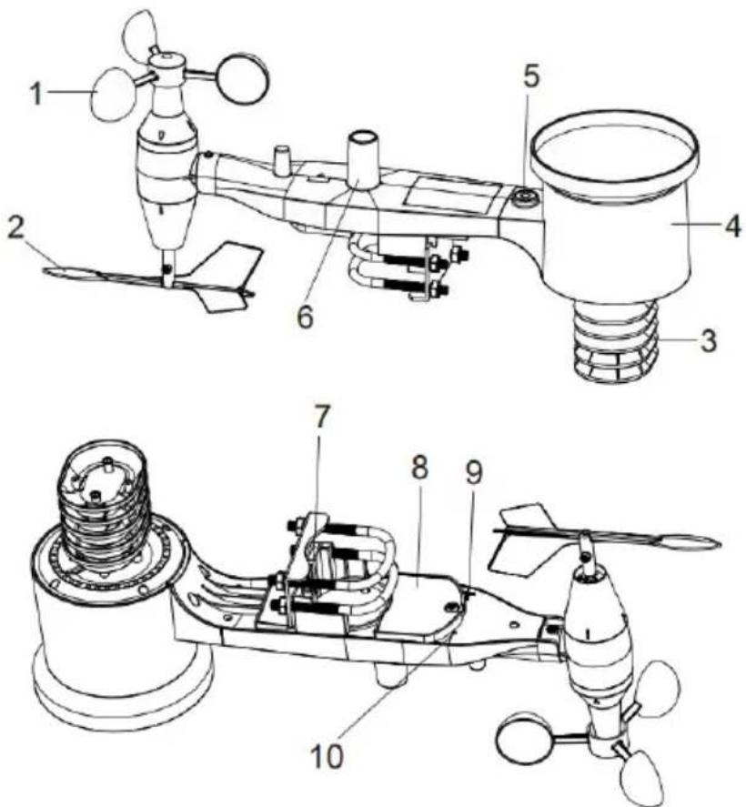
Figure 1: Sensor assembly components
Table 3: Sensor assembly detailed items
| 1 Wind speed cups | 6 Antenna |
| 2 Wind vane | 7 U-Bolts |
| 3 Thermo- and hygro-meter sensors | 8 Battery compartment door |
| 4 Rain collector | 9 Reset button |
| 5 Bubble level | 10 LED (red) to indicate data transmission |
4.2.1 Install U-bolts and mounting pole
Installation of the U-bolts, which are in turn used to mount the sensor package on a pole, requires installation of an included metal plate to receive the U-bolt ends. The metal plate, visible in Figure 2, has four holes through which the ends of the two U-Bolts will fit. The plate itself is inserted in a groove on the bottom of the unit. Note that one side of the plate has a straight edge (which goes into the groove), the other side is bent at a 90-degree angle and has a curved profile (which will end up "hugging" the mounting pole). Once the metal plate is inserted, remove nuts from the U-Bolts and insert both U-bolts through the respective holes of the metal plate as shown in Figure 2.
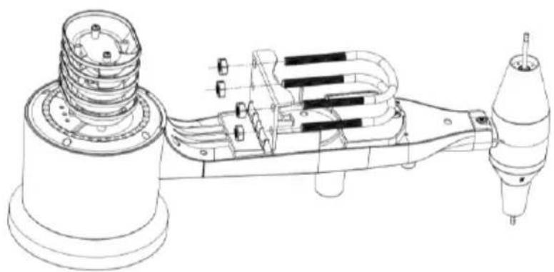
Figure 2: U-Bolt installation
Loosely screw on the nuts on the ends of the U-bolts. You will tighten these later during final mounting. Final assembly is shown in Figure 3.
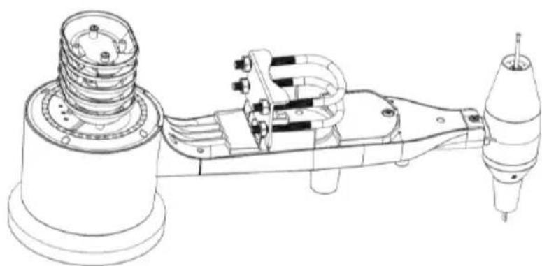
Figure 3: U-Bolts and nuts installed
The plate and U-Bolts are not yet needed at this stage but doing this now may help avoid damaging wind vane and wind speed cups later on.
4.2.2 Install wind vane
Push the wind vane onto the shaft on the bottom of the sensor, until it stops moving further, as shown in figure 4.
Tighten the set screw, with a Philips screw driver (size PH0), until the wind vane cannot be removed from the axle, as shown in figure 4. Make sure the wind vane spin freely. The wind vane's movement has a small amount of friction, which is helpful in providing steady wind direction measurements.
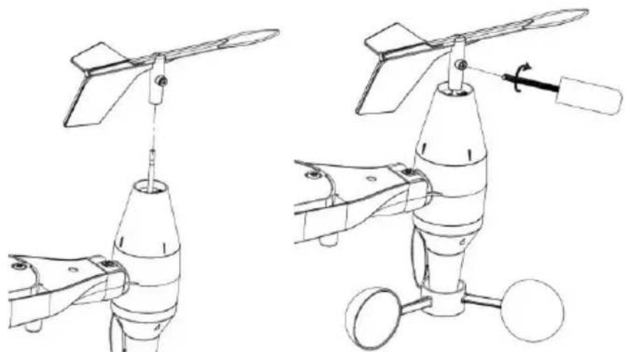
Figure 4: Wind vane installation diagram
4.2.3 Install wind speed
Push the wind speed cups into the shaft as shown in figure 5.
Tighten the set screw with screw driver. Make sure the wind speed cups can spin freely.
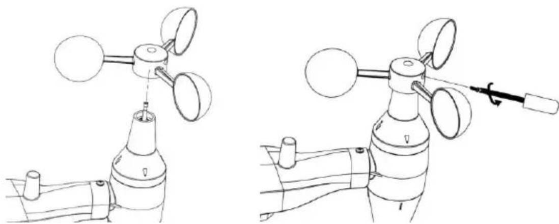
Figure 5: Wind speed cup installation diagram
4.2.4 Install Rain Gauge
Install the rain gauge funnel. Rotate clockwise to attach the funnel to the outdoor sensor.
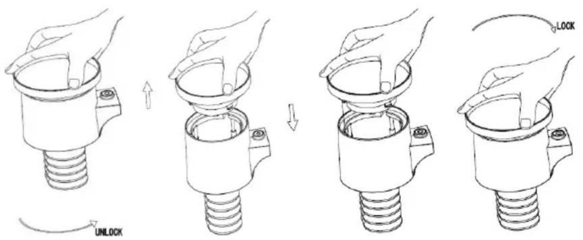
Figure 6: Rain gauge installation and maintenance
4.2.5 Install Batteries
Insert 2XAA batteries in the battery compartment. The LED indicator on the back of the transmitter will turn on for four seconds and normally flash once every 16 seconds (the sensor transmission update period).
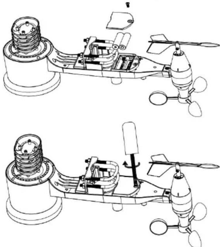
Figure 7: Battery installation diagram
Note: If no LED light up or is permanently on, make sure the batteries are inserted the correct way or a proper reset has happened. Do not install the batteries backwards. You can permanently damage the outdoor sensor.
Note: We recommend 1. 5V lithium batteries. We do not recommend rechargeable batteries. They have lower voltages, they do not operate well at wide temperature ranges, and do not last as long, resulting in poorer reception.
4.2.6 Mount assembled outdoor sensor package
4.2.6.1 Before you mount
Before proceeding with the outdoor mounting detailed in this section, you may want to skip to setup instructions in section 6.2 and onwards first, while you keep the assembled outdoor sensor package nearby (although preferably not closer than 5 ft. from the console). This will make any troubleshooting and adjustments easier and avoids any distance or interference related issues from the setup.
After setup is complete and everything is working, return here for outdoor mounting. If issues show up after outdoor mounting they are almost certainly related to distance, obstacles etc.
4.2.6.2 Mounting
You can attach a pipe to a permanent structure and then attach the sensor package to it (see Figure 8). The U-Bolts will accommodate a pipe diameter of 1-2 inches (pipe not included).
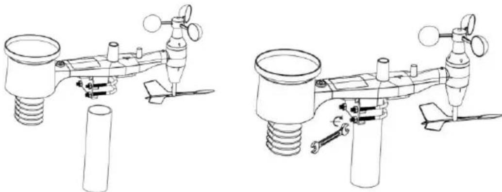
Figure 8: Sensor package mounting diagram
Finally, place the sensor package on top of the prepared mounting pipe. The U-Bolts should be loose enough to allow this but loosen the nuts as necessary. Once placed, hand tightens all four nuts, taking care to do so evenly.
Now you will need to align the whole package in the proper direction by rotating it on top of the mounting pipe as needed. Locate the arrow labeled "WEST" that you will find on top of the sensor package right next to the light sensor. You must rotate the whole sensor package until this arrow points due West. To achieve proper alignment, it is helpful to use a compass (many cell phones have a compass application).
Once rotated in the correct orientation, lightly tighten the bolts a little more (use a wrench) to prevent further rotation.
Note: Use the bubble level next to the rain sensor to make sure the sensor array is completely level. If the sensor is not level then the rain gauge will measure inaccurately.
In the event that the sensor array is not transmitting, reset the sensor array.
With an open ended paperclip, press and hold the RESET BUTTON for three seconds and resynchronize with console by powering down and up the console. Please put the console with the sensor array about 3 meters away.
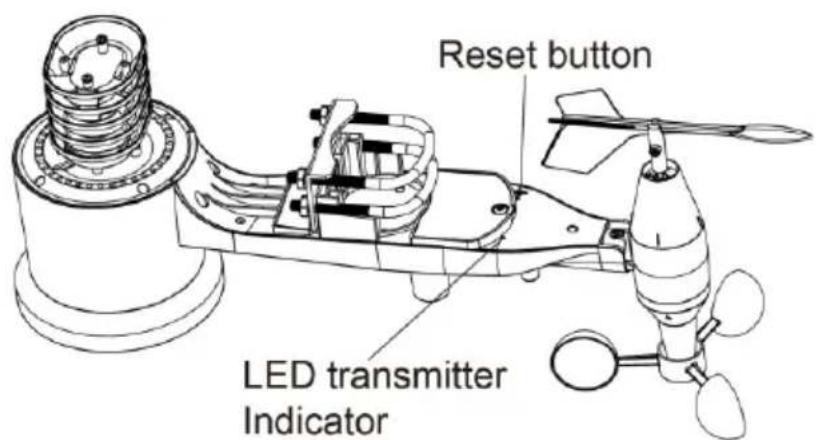
Figure 9: Reset button and Transmitter LED location
4.3 Best Practices for Wireless Communication
Note: To insure proper communication, mount the remote sensor(s) upright on a vertical surface, such as a wall. Do not lay the sensor flat.
Wireless communication is susceptible to interference, distance, walls and metal barriers. We recommend the following best practices for trouble free wireless communication.
Electro-Magnetic Interference (EMI). Keep the console several feet away from computer monitors and TVs.
Radio Frequency Interference (RFI). If you have other devices operating on
the same frequency band as your indoor and/or outdoor sensors and experience intermittent communication between sensor and console, try turning off these other devices for troubleshooting purposes. You may need to relocate the transmitters or receivers to avoid the interference and establish reliable communication. The frequency used is 868.
- Line of Sight Rating. This device is rated at 300 feet line of sight (no interference, barriers or walls) but typically you will get 100 feet maximum under most real-world installations, which include passing through barriers or walls.
- Metal Barriers. Radio frequency will not pass through metal barriers such as aluminum siding. If you have metal siding, align the remote and console through a window to get a clear line of sight.
The following is a table of reception loss vs. the transmission medium. Each "wall" or obstruction decreases the transmission range by the factor shown below.
Table 5: RF Signal Strength reduction
| Medium | RF Signal Strength Reduction |
| Glass (untreated) | 5-15% |
| Plastics | 10-15% |
| Wood | 10-40% |
| Brick | 10-40% |
| Concrete | 40-80% |
| Metal | 90-100% |
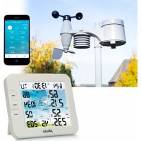
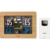
4.4 Display console
The front and back of the display console is shown in Figure13.
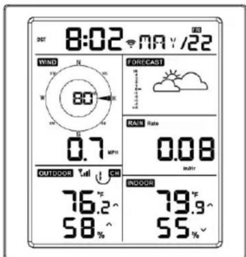
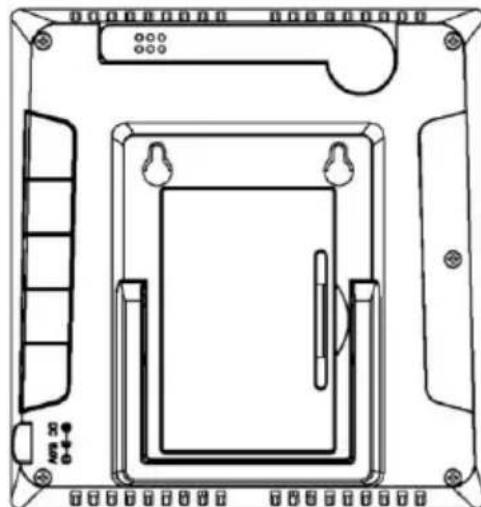
Figure 13: Display console front and back
Reference Figure 14.
(1) Unfold the desk stand and place the console 5 to 10 feet away from the
outdoor sensor.
(2) Remove the battery door on the back of the console and insert 2 × AA good quality Alkaline or Lithium batteries per Figure 14.
(3) Wait several minutes for the remote sensors to synchronize with the display console.
(4) In order to prevent the display console's own temperature rising from affecting the accurate reading of temperature and humidity, the temperature and humidity sensor is placed at the antenna end, away from the station body. Orient the console antenna straight up for accurate indoor temperature and humidity reading.
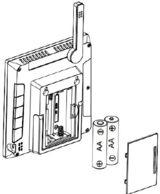
Figure 14: Battery installation for display console
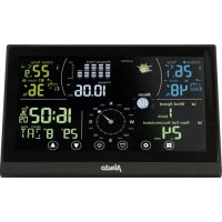
5 Display Console Operation
5.1 Screen Display
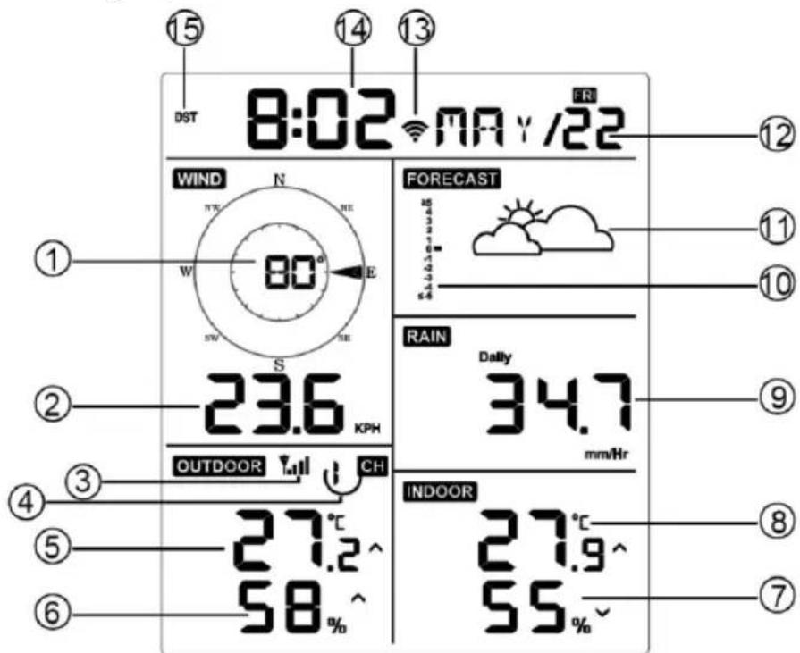
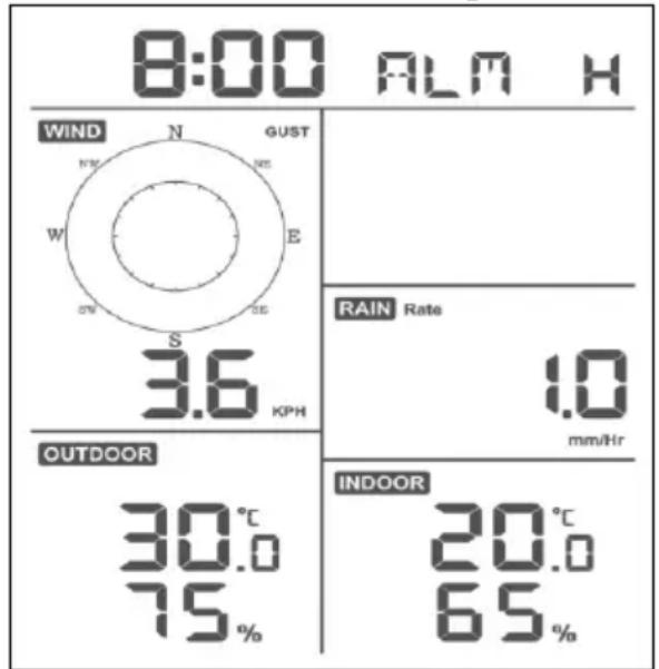
Figure 15: Display Console Screen Layout
Table 6: Display console detailed items
| 1. Wind direction | 9. Rainfall |
| 2. Wind speed | 10. Barometric Pressure graphic |
| 3. RF signal icon | 11. Weather forecast |
| 4. 8 Channel Indoor/Outdoor Thermo-Hygrometer recycle icon (optional) | 12. Date |
| 5. Outdoor temperature | 13. WIFI signal icon |
| 6. Outdoor humidity | 14. Time |
| 7. Indoor humidity | 15. Daylight Savings Time (DST) |
| 8. Indoor temperature | |
5.2 Initial Display Console Set Up
Insert the batteries to power up the display console.
The unit will show software version and frequency information 2 seconds after power reset.
The unit will turn on all segments of the LCD for 3 seconds after power reset, then the unit will start to register the outdoor channel for 3 minutes.
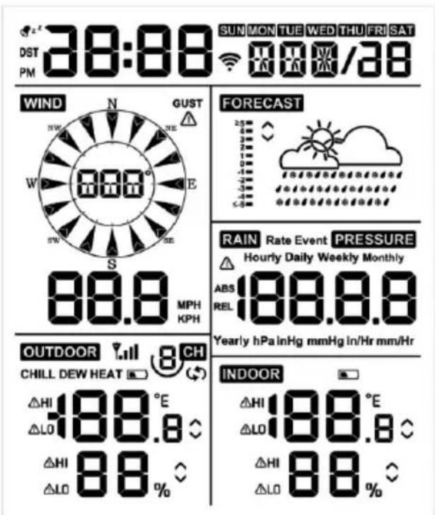
Figure 16
5.2.1 Key function
The console has five keys for easy operation
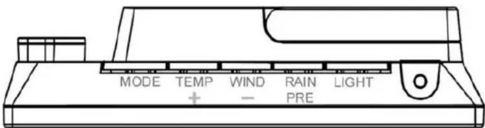
Figure 17
| Key | Description |
| MODE | Press and hold for two seconds to enter the Set Mode.
Press to switch between Normal Mode, Max Mode, Min Mode, High Alarm Mode, Low Alarm Mode, MAC address display Mode |
Table 7: Key function
| Key | Description |
| TEMP+ | While the console using battery supply only, press this button to switch display between Outdoor Temperature, Wind Chill, Dew Point, Heat Index. While using DC supply, press the button to switch display between Outdoor Temperature, Chill, Dew Point, Heat Index, 8 channel temperature and humidity (optional), Circle Mode. |
| WIND - | Press to switch between average wind speed and, wind gust.
Press and hold for two seconds to switch the wind direction to display in degrees or in letters. |
| RAIN/PRE | Press and hold for two seconds switch between Rain and Pressure.
While in Rain mode, press to switch between Rain Rate, Rain Events, Hourly Rain, Daily Rain, Weekly Rain, Monthly Rain and Yearly Rain
While in Pressure mode, press to switch between Relative pressure and Absolute pressure |
| LIGHT | Press to adjust the LCD backlight brightness (high, medium and off); only available when powered by USB connection
Press to exit the SET mode at any time. |
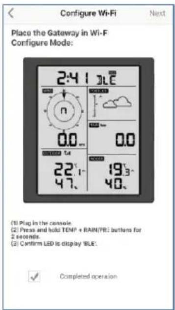
| TEMP+ (and) RAIN PRE | Press this two buttons at the same time for 4 seconds to activate BLE function for Wi-Fi configuration (refer to section 8.1.2) |
5.3 Setting mode
Note: DST, Time Zone setting can only be programmed via WS View Plus APP. You will need to set time zone info properly if you have the console connected to internet and these settings need to be adjusted for your setup, otherwise console will be synchronized to default setting if you don't setup these parameters on the APP properly.
Press and hold the MODE button for two seconds to enter the Set Mode. To proceed to the next setting, press (do not hold) the MODE button.
To exit the SET mode at any time, press the LIGHT button.
Table 8 summarizes the set mode sequence and commands.
Factory Default Reset: [MODE] + [LIGHT] for 5s
| Command | Mode | Settings | Image |
| [MODE] + 2 seconds | Enter Set Mode, Beep On or Off | Press [TEMP+] or [WIND-] to switch OFF and ON. This will prevent the beep from sounding when pressing any button. | ON | bEEP |
| [MODE] | Clear Max/Min | Press [TEMP+] or [WIND-] to switch OFF and ON. When set to ON, the minimum and maximum values reset every day at midnight (00:00). When set to OFF, the minimum and maximum values must be reset manually. | RST ON HILO |
| [MODE] | 12 hour / 24 Hour Format | Press [TEMP+] or [WIND-] to switch hour format between 12 hour and 24-hour format. | 5:08 m/y/n |
| [MODE] | Hour | Press [TEMP+] or [WIND-] to adjust hour up or down. |
| [MODE] | Minute | Press [TEMP+] or [WIND-] to adjust minute up or down. |
| [MODE] | Year | Press [TEMP+] or [WIND-] to adjust year up or down |
| [MODE] | Month | Press [TEMP+] or [WIND-] to adjust month up or down |
| [MODE] | Day | Press [TEMP+] or [WIND-] to adjust day up or down |
Table 8: Set mode sequence and commands summarization
| Command | Mode | Settings | Image |
| [MODE] | Pressure Units of Measure | Press [TEMP+] or [WIND-] to change units of measure between hap, mmHg or inHg. | PRESSURE REL 13.2 hPa |
| [MODE] | Relative Pressure Calibration | Press [TEMP+] or [WIND-] to adjust relative pressure up or down Reference Section 5.4.3for details on calibration of relative pressure. |
| [MODE] | Temperature Units of Measure | Press [TEMP+] or [WIND-] to change temperature units of measure between °F and °C. | OC OC |
| [MODE] | Wind Units of Measure | Press [TEMP+] or [WIND-] to change wind units of measure between km/h, mph, knots, m/s and bft. | WIND N NE W S O KPH |
| [MODE] | Rain Units of Measure | Press [TEMP+] or [WIND-] to change rain units of measure between in and mm. | RAIN Dally 0.56 in |
| [MODE] | Exit Set Mode | | |
[MODE] + 2 seconds means to press and hold the MODE button for two seconds.
[MODE] means to press the MODE button.
5.4 Barometric Pressure Display
5.4.1 Viewing Absolute vs. Relative Pressure
Press and hold [RAIN/PRE] for two seconds switch between Rain and Pressure. While in Pressure mode Press [RAIN/PRE] to switch between absolute and relative pressure
Absolute pressure is the measured atmospheric pressure, and is a function of altitude, and to a lesser extent, changes in weather conditions.
Absolute pressure is not corrected to sea-level conditions.
Relative pressure is corrected to sea-level conditions. For further discussion of relative pressure and calibration, reference Section 5.4.3.
5.4.2 Rate of Change of Pressure Graph
The rate of change of pressure graphic is shown to the left of the weather forecast icons and signifies the difference between the daily average pressure and the 30-day average (in hPa).
5.4.3 Relative Pressure Calibration Discussion
The calibration was set on WS View Plus app. To compare pressure conditions from one location to another, meteorologists correct pressure to sea-level conditions. Because the air pressure decreases as you rise in altitude, the sea-level corrected pressure (the pressure your location would be at if located at sea-level) is generally higher than your measured pressure.
Thus, your absolute pressure may read 726. 95mmHg (969 mb) at an altitude of 305m , but the relative pressure is 762mmHg (1016 mb).
The standard sea-level pressure is 759. 97mmHg (1013 mb). This is the average sea-level pressure around the world. Relative pressure measurements greater than 759. 97mmHg (1013 mb) are considered high pressure and relative pressure measurements less than 759. 97mmHg are considered low pressure.
To determine the relative pressure for your location, locate an official reporting station near you (the internet is the best source for real time barometer conditions, such as Weather. com or Wunderground. com), and set your weather station to match the official reporting station.
5.5 Rain Display
5.5.1 Rain Increments of Measure
Press and hold [RAIN/PRE] for two seconds switch between Rain and Pressure. While in Rain mode press the [RAIN/PRE] to switch between Rain Rate (mm/hr), Rain Event, Rain Hourly, Daily Rain, Weekly Rain, Monthly Rain and Yearly Rain.
5.5.2 Increments of Rain Definitions
- Hourly rain rate or mm/HR is defined as the last 10 minutes of rainfall, multiplied by six (10 minutes x 6 = 1 hour). This is also referred to as instantaneous rain per hour.
- Event is defined as continuous rain, and resets to zero if rainfall accumulation is less than 1mm (0.039 in) in a 24-hour period.
Daily is defined as the rainfall since midnight (00:00).
- Weekly is defined as the calendar week total and resets on Sunday morning at midnight (Sunday thru Saturday).
Monthly is defined as the calendar month total and resets on the first day of the Month.
- Yearly is defined as the total rainfall from January 1 to December 31.
5.6 Wind Display
Press the [WIND -] button to switch between average wind speed and, wind gust.
Press and hold the [WIND -] button for two seconds to switch the wind direction to display in degrees or in letters.
- Wind speed is defined as the average wind speed in the 16 seconds update period.
- Wind gust is defined as the peak wind speed in the 16 seconds update period.
5.7 Temperature Display
If temperature is lower than minimum range, the temperature field will display dashes (--. -) .
If temperature is higher than maximum range, the temperature field will display dashes (--. -) .
5.7.1 Wind Chill, Dew Point and Heat Index Display
Press the [TEMP] button to switch between Outdoor Temperature, Wind Chill, Dew Point, Heat Index.
The device supports up to 8 additional thermo-hygrometer sensors. If you have the extra sensors, press the [TEMP +] button to switch between Outdoor Temperature, Wind Chill, Dew Point, Heat Index, 8 channel temperature and humidity, Circle Mode
5.8 Alarms
5.8.1 Viewing High and Low Alarms
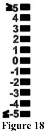
To view the high alarm settings, press MODE button a third time, and the high alarms will be displayed, as shown in Figure 19 (a).
To view the low alarm settings, press the MODE button a fourth time, and the low alarms will be displayed, as shown in Figure 19 (b).
To return to normal mode, press the LIGHT button again.
(a)

(b)
Figure 19
5.8.2 Setting High and Low Alarms
While the High Alarm is displayed (reference Section 5.8.1), press and hold the MODE button for 2 seconds to enter the High Alarm Set Mode.
While the Low Alarm is displayed (reference Section 5.8.1), press and hold the MODE button for 2 seconds to enter the Low Alarm Set Mode.
To save and proceed to the next alarm setting, press the Mode button.
To exit the High Alarm Set Mode at any time, press the LIGHT button.
Table 9 summarizes the alarm mode sequence and commands.
| Command | Mode | Settings |
| [MODE] + 2 seconds | Enter High Alarm Set Mode, Alarm Hour | Press [TEMP+] or [WIND-] to adjust alarm hour up or down.Press [RAIN/PRE] to turn the time alarm on or off. When the alarm is on, the alarm time icon will appear. |
| [MODE] | Alarm Minute | Press[TEMP+] or [WIND-] to adjust alarm minute up or down.Press [RAIN/PRE] to turn the time alarm on. The alarm time icon will appear.Press [RAIN/PRE] again to turn the time alarm off. The alarm time icon will disappear. |
| [MODE] | Alarm High Indoor Temperature | Press [TEMP+] or [WIND-] to adjust alarm value up or down.Press [RAIN/PRE] to turn the alarm on.The alarm icon will appear.Press [RAIN/PRE] to turn the alarm off. The alarm icon will disappear. |
| [MODE] | Alarm High Indoor Humidity | Press [TEMP+] or [WIND-] to adjust alarm value up or down.Press [RAIN/PRE] to turn the alarm on.The alarm icon will appear.Press [RAIN/PRE] to turn the alarm off. The alarm icon will disappear. |
| [MODE] | Alarm High Outdoor Temperature | Press [TEMP+] or [WIND-] to adjust alarm value up or down.Press [RAIN/PRE] to turn the alarm on.The alarm icon will appear.Press [RAIN/PRE] to turn the alarm off.The alarm icon will disappear. |
| [MODE] | Alarm High Outdoor Humidity | Press [TEMP+] or [WIND-] to adjust alarm value up or down.Press [RAIN/PRE] to turn the alarm on.The alarm icon will appear.Press [RAIN/PRE] to turn the alarm off.The alarm icon will disappear. |
| [MODE] | Alarm High Wind Gust | Press [TEMP+] or [WIND-] to adjust alarm value up or down.Press [RAIN/PRE] to turn the alarm on.The alarm icon will appear.Press [RAIN/PRE] to turn the alarm off.The alarm icon will disappear. |
| [MODE] | Alarm High Rain Rate | Press [TEMP+] or [WIND-] to adjust alarm value up or down.Press [RAIN/PRE] to turn the alarm on.The alarm icon will appear.Press [RAIN/PRE] to turn the alarm off.The alarm icon will disappear. |
Table 9: Alarm mode sequence and commands summarization
| Command
[MODE] | Mode
Alarm Low Indoor Temperature | Settings
Press [TEMP+] or [WIND-] to adjust alarm value up or down.
Press [RAIN/PRE] to turn the alarm on.
The alarm icon will appear.
Press [RAIN/PRE] to turn the alarm off.
The alarm icon will disappear.
Press [TEMP+] or [WIND-] to adjust alarm value up or down.
Press [RAIN/PRE] to turn the alarm on.
The alarm icon will appear.
Press [RAIN/PRE] to turn the alarm off.
The alarm icon will disappear.
Press [TEMP+] or [WIND-] to adjust alarm value up or down.
Press [RAIN/PRE] to turn the alarm on.
The alarm icon will appear.
Press [RAIN/PRE] to turn the Alarm off.
The alarm icon will disappear.
Press [TEMP+] or [WIND-] to adjust alarm value up or down.
Press [RAIN/PRE] to turn the alarm on.
The alarm icon will appear.
Press [RAIN/PRE] to turn the alarm off.
The alarm icon will disappear. |
| [MODE] | Alarm Low Indoor Humidity |
| [MODE] | Alarm Low Outdoor Temperature |
| [MODE] | Alarm Low Outdoor Humidity |
| [MODE] | Exit alarm settings mode. |
| [MODE] + 2 seconds means to press and hold the MODE button for 2 seconds. |
| [MODE] means to press the MODE button. |
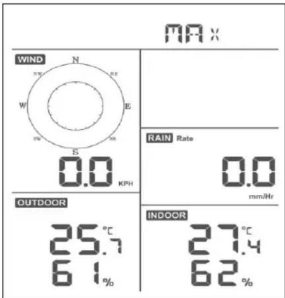
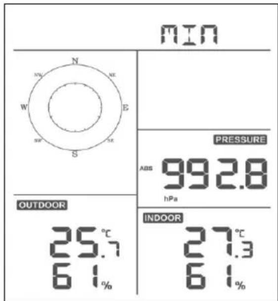
5.9 Max/Min Mode
5.9.1 Viewing Max/Min Values
To view the max value, press the MODE button, and the max values will be displayed, as shown in Figure 20 (a). To clear the max values, press and hold the MODE button while the max values are displayed.
To view the min value, press the MODE button again, and the min values will be displayed, as shown in Figure 20 (b). To clear the min values, press and hold the MODE button while the min values are displayed.
To return to normal mode, press the LIGHT button.
(a)
(b)
Figure 20
5.9.1.1 Display Wind Chill, Heat Index vs. Dew Point Max/Min Values
While the max values are displayed as outlined in Section 5.9, press the TEMP + button once to view the wind chill, twice to view the dew point, third to view the heat index and a fourth time to return to outdoor temperature.
While the min values are displayed as outlined in Section 5.9, press the TEMP + button once to view the wind chill, twice to view the dew point, third to view the heat index and a fourth time to return to outdoor temperature.
5.9.1.2 Display Wind Speed vs. Wind Gust Max Values
While the max values are displayed as outlined in Section 5.9, press the WIND- button once to view the max wind gust, and twice to return to wind speed.
5.9.1.3 Display Hourly Rain, Rain Rate
While the max values are displayed as outlined in Section 5.9, press the RAIN button once to view the max hourly rain, twice to view the rain rate.
5.9.1.4 Display Absolute and Relative Pressure Min and Max Values
While the max values are displayed as outlined in Section 5.9, press and hold the RAIN/PRE button for two seconds to enter pressure display, press RAIN/PRE button to switch between Relative pressure and Absolute pressure.
While the min values are displayed as outlined in Section 5.9, press and hold the RAIN/PRE button for two seconds to enter pressure display, press RAIN/PRE button to switch between Relative pressure and Absolute pressure
To return to normal mode, press the LIGHT button.
5.10 Resynchronize Wireless Sensor
While in outdoor TH/wind chill/dew point/heat index display mode press TEMP + button for 5 seconds, and the console will re-register the outdoor sensor array
While in 1-8 channel Thermo-hygro sensor display mode press TEMP+ button for 5 seconds, and the console will re-register the current channel outdoor sensor.
While in Circle Mode press TEMP+ button for 5 seconds, and the console will re-register the sensor array and 1-8 channel sensors.
5.11 Backlight Operation
Press LIGHT button for 2s, will wake up Wi-Fi chip from power saving state, the date display will turn to show
"WAK", saying that at battery power supply state, the Wi-Fi existed power saving mode, and it is very useful
when Live Data feature need to be activated on WS View Plus app for live data reference, as during Wi-Fi power saving mode, the system is not responding to WS View Plus app commands quickly.

5.11.1 With USB cable (included)
The backlight can only be continuously on when the console display is powered on with the USB cable.
Press the LIGHT button to adjust the brightness between High, Middle, Low and Off.
5.11.2 Without USB Power supplied
Press any button briefly to turn on the backlight temporarily for 15 seconds.
5.12 Tendency Arrows
Tendency arrows allow you to quickly determine of temperature or pressure are rising and falling in a three-hour update period, updated every 30 minutes.
Table 10 defines the conditions for rising and falling pressure every 3 hours.
Table 11
| Tendency indicators | Condition | Humidity Change per 3 Hours | Temperature Change per 3 Hours |
| \(\smile\) | Rising | Rising > 3% | Rising > 1°C / 2°F |
| None | Steady | Change ≤ ±3% | Change ≤ ± 1°C / 2°F |
| \(\smile\) | Falling | Falling > 3% | Falling > 1°C / 2°F |
Table 10: Tendency indicators summarization
5.13 Wireless Signal Quality Indicator
The wireless signal strength displays reception quality. If no signal is lost, the signal strength indicator will display four bars. If the signal is lost once, three bars will be displayed, as shown in Figure 26.
Four Bars
Three Bars
No signal loss
Lost signal once
5.14 Weather Forecasting
The five weather icons are Sunny, Partly Cloudy, Cloudy, Rainy and Snowy.
The forecast icon is based on the rate of change of barometric pressure. Please allow at least one month for the weather station to learn the barometric pressure over time.
Table 12: Weather forecasting summarization
| Sunny | Partly Cloudy | Cloudy | Rainy | Snowy |
| FORECAST | FORECAST | FORECAST | FORECAST | FORECAST |
| Pressure increases for a sustained period of time | Pressure increases slightly, or initial power up | Pressure decreases slightly | Pressure decreases for a sustained period of time | Pressure decreases for a sustained period of time and temperature is below freezing |
Note:
When the pressure decreases dramatically, the rainy icon will flash to indicate stormy.
When the pressure decreases dramatically and the temperature is below freezing, the snowy icon will flash to indicate blizzard.
5.14.1 Storm Alert
If there is a rapid drop in barometric pressure, the forecast icon will flash.
5.14.2 Weather Forecasting Description and Limitations
In general, if the rate of change of pressure increases, the weather is generally improving (sunny to partly cloudy). If the rate of change of pressure decreases, the weather is generally degrading (cloudy, rainy). If the rate of change is relatively steady, it will read partly cloudy.
The reason the current conditions do not match the forecast icon is because the forecast is a prediction 24-48 hours in advance. In most locations, this prediction is only 70% accurate and it is a good idea to consult the National Weather Service for more accurate weather forecasts. In some locations, this prediction may be less or more accurate. However, it is still an interesting educational tool for learning why the weather changes.
The National Weather Service (and other weather services such as Accuweather and The Weather Channel) have many tools at their disposal to predict weather conditions, including weather radar, weather models, and detailed mapping of ground conditions.
6 Specification:
Outdoor data
| Transmission distance in open field | : 100M/300FT |
| Frequency | : 868.29 MHz (-9.42 dBm)2412 - 2472 MHz (< 20 dBm) |
| Temperature range | : -40°C- 60°C (-40°F to +140°F) |
| Accuracy | : +/- 1 °C |
| Resolution | : 0. 1°C |
| Measuring range rel. humidity | : 1% ~ 99% |
| Accuracy | : +/- 5% |
| Rain volume display | : 0 - 9999mm(show --- if outside range) |
| Accuracy | : + / - 10% |
| Resolution | : 0. 1mm (if rain volume < 1000mm)1mm (if rain volume > 1000mm) |
| Wind speed | : 0-50m/s (0~100mph)(show --- if outside range) |
| Accuracy | : +/- 1m/s (wind speed< 5m/s)+/-10%(wind speed > 5m/s) |
| Measuring interval thermo-hygro sensor | : 16 s |
Indoor data
Indoor temperature range : 0^ - 50^ (32°F to + 122°F) (show --- if outside range)
Resolution : 0.1^
Measuring range rel. Humidity : 1% 99%
Resolution : 1%
Measuring range air pressure : 700-1100hPa (525. 02-825. 5 mmHg)
Accuracy +/-3hpa
Resolution : 0.1hPa (0.25 mmHg)
Alarm duration 120s
Measuring interval indoor data 60s
Power consumption
- Base station: 5V DC (USB to 2.5*0.7mm DC 5V power plug connector cable included)
- Base station: 2 × Lithium AA batteries (not included)
- Remote sensor: 2x Lithium AA batteries (not included)
7 Live Internet Publishing
Your console is capable of sending your sensor data to select internet-based weather services. The supported services are shown in the table below:
| Hosting Service | Website | Description |
| Ecowitt Weather | https://www.ecowitt.net | Ecowitt is a new weather server that can host a bunch of sensors that other services don’t support. |
| Weather Underground | WeatherUnderground.com | Weather Underground is a free weather hosting service that allows you to send and view your weather station data real-time, view graphs and gauges, import text data for more detailed analysis and use iPhone, iPad and Android applications available at Wunderground.com. Weather Underground is a subsidiary of |
Table 13: Supported weather services
| Hosting Service | Website | Description |
| | The Weather Channel and IBM. |
| Weather Cloud | WeatherCloud.net | Weathercloud is a real-time weather social network formed by observers from around the world |
| Weather Observation Website (WOW) | http://wow.metoffice.gov.uk/ | WOW is a UK based weather observation website. WOW allows anyone to submit their own weather data, anywhere in the world. |
| Customized Website | | Supports uploading to your customized website, if the website has the same protocol with Wunderground or Ecowitt |
To send weather data to these services you must configure console to be connected to your Wi-Fi router for internet access.
During console credentials setting up, firmware updating, the communication between your phone and console is based on Blue Tooth (BLE), so your phone needs to be 5 meter within the console radius. When the device has connected to your network which also your phone is connected, then further setup like live data, calibration, date, time zone etc will be based on your WLAN and it is not so distance sensitive.
Note1: The Wi-Fi chip equipped on this console supports 2.4GHz mode only with 2.0MHz CLK rate. Thus, some latest Wi-Fi routers or AP has to be manually turned on 2.4GHz mode and even need to enable the latency mode to host this device. Those known router or AP devices is:
Ubiquiti UAP-PRO
Or it is necessary even to switch this option off:
Please check your Wi-Fi router or AP devices setting and contact the router manufacturer if you still have problems in connecting the console to your Wi-Fi network.
Note:
If you are testing the setup with the outdoor sensor package nearby and indoor, you may want to consider connecting to Wi-Fi, but not yet configuring any of the weather services. The reason is that while indoor the temperatures and humidity recorded by the outdoor sensor, and as reported to the weather service(s) will reflect indoor conditions, and not outdoor conditions. Therefore, they will be incorrect. Furthermore, the rainfall bucket may be tripped during handling, causing rain to register while it may not actually have been raining. One way to prevent this is to follow all instructions, except to use an incorrect password, on purpose! Then, after final outdoor installation, come back and change the password after clearing console history. That will start uploading to the services with a clean slate.
7.1.1 Download mobile application
Wi-Fi configuration is done using your mobile device, either iOS or Android. Start by downloading the WS View Plus application from the Apple App Store or Google Play store, as appropriate for your device.
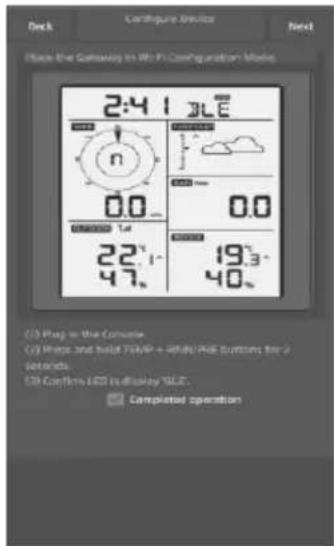
Press button "TEMP/+" and "RAIN PRE" button at the same time and hold for 2s will activate configuration mode. The following display will be on at the Date section on LCD:

If you own an Apple iOS device, refer to Section 7.1.2.1. If you own a Android device, refer to Section 7.1.2.2.
7.1.2.1 Apple iOS user
Run the WS View Plus app from your mobile device's home screen.
When prompted "Allow WS View Plus to access your location?" choose" Allow While Using App." If you do not select this option, your phone will not connect to the weather station:
Configure Device
1) Tap on the settings icon and select "Configure New Device".
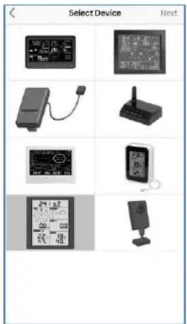
2) Select your weather station type. Tap Next
3) Follow the prompts; tick the box to confirm "completed operation", press Next.
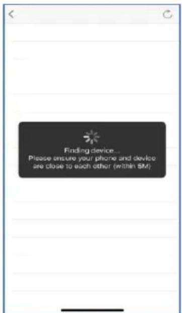
4) The app will search the device. Please ensure your phone and device are close to each other within 5m
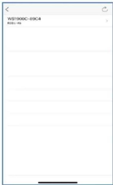
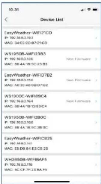
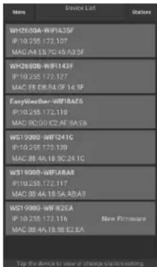
5) If you have more than one device they will all be listed. Select the device. The last four digits of device ID is the same as its last four digits of MAC address. If you cannot find your device ID, press refresh to update.
6) The app will connect to the console automatically.
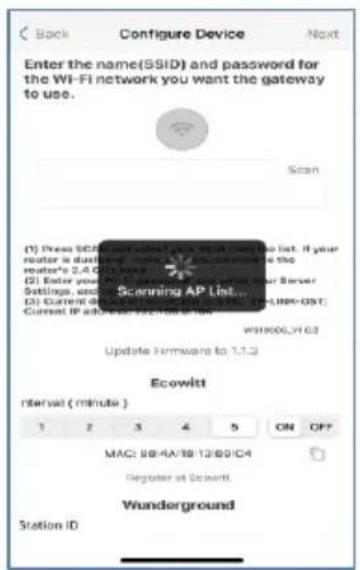
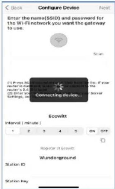
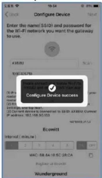
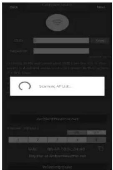
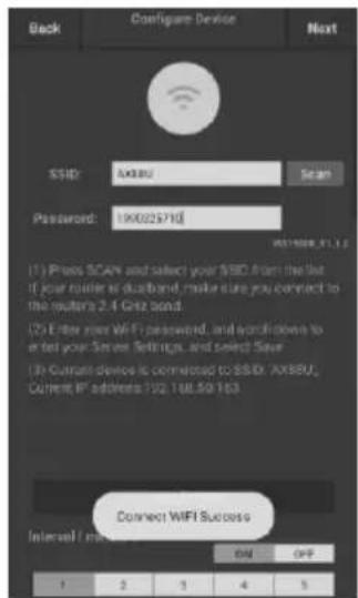
7) *Press Scan and select your SSID from the list. If it is a dual band router and the SSIDs are different, make sure you connect to the 2.4 GHz band. Enter the WiFi password.
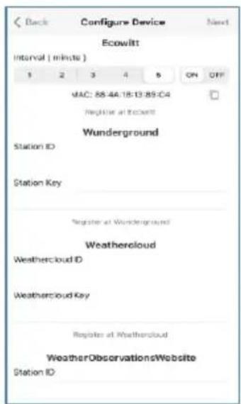
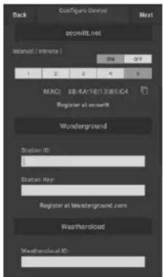
8) If you already have an Ecowitt account you can connect your account. Tap ON and select an upload interval in minutes Make a note of the MAC address. If not then skip this step
9) If you already have an Weather underground account you can connect your account. Enter the Station ID and Station Key obtained from Wunderground.com into this panel. If not then skip this step
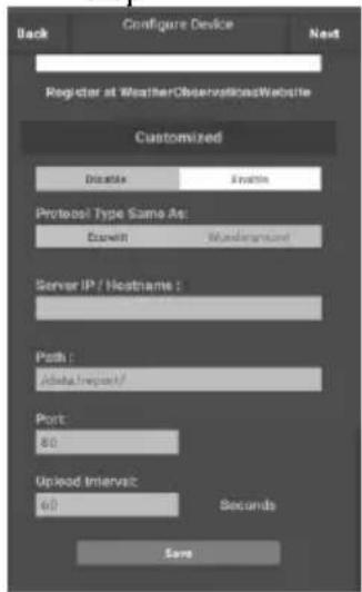
*Note: After step 7) you can set the uploading to weather servers (Ecowitt Weather / Weather Underground / Weather Cloud / WOW / Customized Website) on this page or do that after the Wi-Fi configuration done.
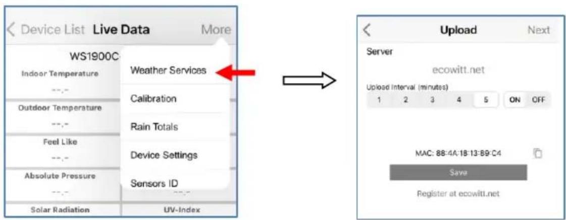
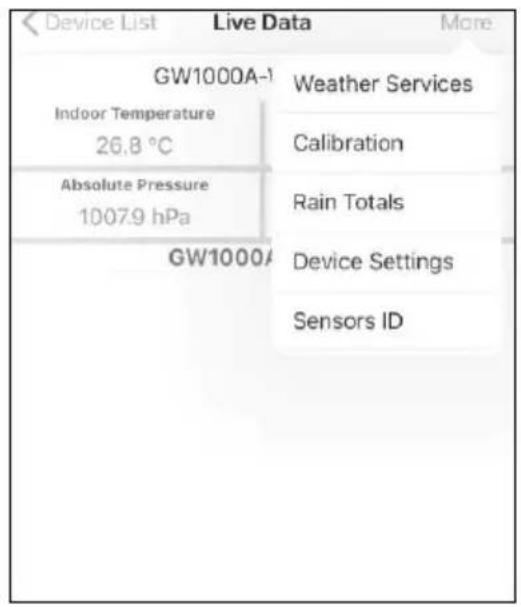
If you configured weather services after the Wi-Fi configuration done, select your device from the device list. This will bring you to the "Live Data" screen.
On the "Live Data" screen, press the "More" button in the upper right and select "Weather Services" from the menu. This will bring you to the "Upload" screen for the device.
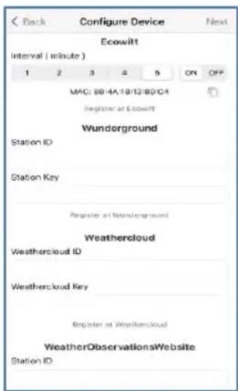
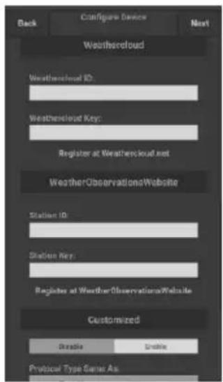
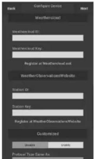
10) If you already have an WeatherCloud account you can connect your account.
WeatherCloud.net. Enter the Station ID and Password into this panel.
If not then skip this step
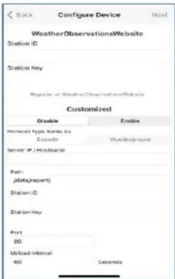
11) If you already have an WeatherObservations Web account you can connect your account.
Enter the Station ID and Password into this panel
If not then skip this step
12) Upload your data to your own sever.
The website should have the same protocol with Wunderground or Ecowitt. Input all the information needed.
13) Tap Next
14) Once completed successfully, your device ID, IP address and MAC address will be displayed If you have more than one device, they will all be listed. To change any of the console settings, click on the device field.
15) Select the device to see the live date.
7.1.2.2 Android user:
Now activate the application you have downloaded on your mobile device. The following instructions will generally show screen shots for the Android application side by side.
1) Press "Configure a New Device"
2) Select the device you have from the device list, then press Next
3) Follow the prompts, tick the box to confirm "completed operation", press Next.
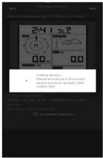
4) The app will search the device. Please ensure your phone and device are close to each other within 5m .
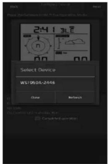
5) If you have more than one device they will all be listed. Select the device. The last four digits of device ID is the same as its last four digits of MAC address. If you cannot find your device ID, press refresh to update.
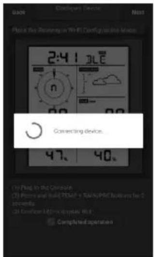
6) The app will connect to the console automatically.

7) Press Scan and select your SSID from the list.
If it is a dual band router and the SSIDs are different, make sure you connect to the 2.4 GHz band.
Enter the WiFi password.
8) If you already have an Ecowitt account you can connect your account.
Tap ON and select an upload interval in minutes
Make a note of the MAC address.
If not then skip this step
10) If you already have an WeatherCloud account you can connect your account.
WeatherCloud.net. Enter the Station ID and Password into this panel.
If not then skip this step
11) If you already have an WeatherObservationsWeb account you can connect your account.
Enter the Station ID and Password into this panel
If not then skip this step
9) If you already have an Weather underground account you can connect your account.
Enter the Station ID and Station Key obtained from Wunderground.com into this panel.
If not then skip this step
12) Upload your data to your own sever.
The website should have the same protocol with Wunderground or Ecowitt. Input all the information needed.
If not then skip this step
13) Tap Next
14) Once completed successfully, your device ID, IP address and MAC address will be displayed.
If you have more than one device, they will all be listed.
To change any of the console settings, click on the device field.
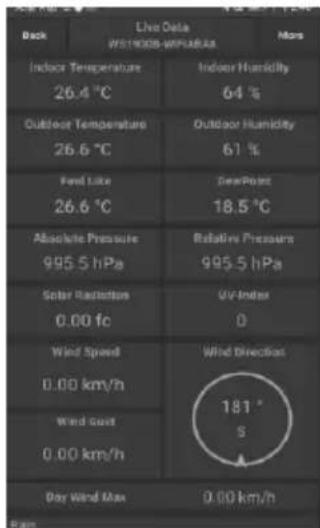
15) Select the device to see the live date. Your mobile device should have been returned to your normal Wi-Fi network setting and the "Live Data" screen should be providing a read-out of your sensors.
How to view the MAC address of device
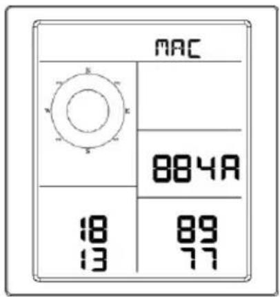
In normal mode press the MODE button five times to view the MAC address.
- For example, the MAC address as shown in Figure 30 is 88:4A:18:13:89:77
8 Other functions on WS View Plus
8.1 Settings
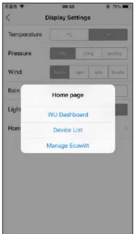
You can set your desired display units or default home page for the app by selecting "Settings" on the submenu:
8.2 Calibration
When on the "Live Data" screen, you can press the "More" button (upper right) to enter the calibration screen.
8.3 Editing Rain totals
When on the "Live Data" screen, you can press the "More" button (upper right) to edit the rain totals if needed.
8.4 Device Settings
On the Live Data page, press "More" on the top-right, and select "Device Settings" to set the following:
- Select sensor type.
- Set time zone.
Reboot Device.
- Reset to Factory Settings.
- Firmware upgrade (only display when new firmware is available)
8.5 Sensor ID
On Live Data page, press More and select "Sensors ID" to set the following:
- View sensor ID, signal strength and battery power condition. 1-4 bars means 1-4 successful successive signal receptions without missed ones.
- Register the sensor when offline.
- Enable or disable the sensor.
- Input the Sensor ID when offline.
9 Maintenance
The following steps should be taken for proper maintenance of your station
- Clean the rain gauge once every 3 months. Rotate the funnel counter-clockwise and lift to expose the rain gauge mechanism, and clean with a damp cloth. Remove any dirt, debris and insects. If bug infestation is an issue, spray the array lightly with insecticide.
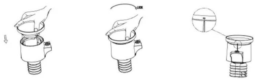
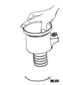
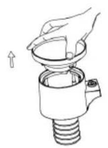
Figure 21: Rain gauge installation and maintenance
- Replace batteries every 1-2 years. If left in too long, the batteries may leak due to environmental challenges. In harsh environments, inspect the batteries every 3 months.
- In snowy environments, spray the top of the weather station with anti-icing silicon spray to prevent snow build up.
10 Troubleshooting Guide
| Problem | Solution |
| Outdoor sensor array does not communicate to the display console. | The sensor array may have initiated properly and the data is registered by the console as invalid, and the console must be reset. Press the reset button as described in Section 4.2. |
| With an open ended papeclip, press the reset button for 3 seconds to re-sync the console with the sensor array about 10 feet away. |
| The LED next to the battery compartment will flash every 16 seconds. If the LED is not flashing every 16 seconds... |
| Replace the batteries in the outside sensor array. |
| If the batteries were recently replaced, check the polarity. If the sensor is flashing every 16 seconds, proceed to the next step. |
| There may be a temporary loss of communication due to reception loss related to interference or other location factors, or the batteries may have been changed in the sensor array and the console has not been reset. The solution may be as simple as powering down and up the console (remove AC power and batteries, wait 10 seconds, and reinsert AC power and batteries). |
| Temperature sensor reads too high in the day time. | Make certain that the sensor array is not too close to heat generating sources or structures, such as buildings, pavement, walls or air conditioning units.
Use the calibration feature to offset installation issues related to radiant heat sources. Reference Section 10.6. |
| Relative pressure does not agree with official reporting station | You may be viewing the absolute pressure, not the relative pressure.
Select the relative pressure. Make sure you properly calibrate the sensor to an official local weather station. Reference Section 5.4.3 for details. |
| Rain gauge reports rain when it is not raining | An unstable mounting solution (sway in the mounting pole) may result in the tipping bucket incorrectly incrementing rainfall. Make sure you have a stable, level mounting solution. |
| Data not reporting to Wunderground. com | 1. Confirm your password or key is correct. It is the password you registered on Wunderground.com. Your Wunderground.com password cannot begin with a non-alphanumeric character (a limitation of Wundeground.com, not the station). Example, oewkrf is not a valid password, but oewkrf is valid.
2. Confirm your station ID is correct. The station ID is all caps, and the most common issue is substituting an O for a 0 (or visa versa). Example, KAZPHOEN11, not KAZPHOEN11
3. Make sure the date and time is correct on the console. If incorrect, you may be reporting old data, not real time data.
4. Make sure your time zone is set properly. If incorrect, you may be reporting old data, not real time data. |
| 5. Check your router firewall settings. The console sends data via Port 80. |
| No Wi-Fi connection | 1. Check for Wi-Fi symbol on the display. If wireless connectivity is successful the Wi-Fi icon displayed in the time field.2. Make sure your modem Wi-Fi settings are correct (network name, and password).3. The console only supports and connects to 2.4 GHz routers. If you own a 5 GHz router, and it is a dual band router, make sure the 2.4GHz router is enabled.4. The console does not support guest networks. |
Manufacturers name and address: Dong Guan ShiJie Hua Xu Electronics Factory, No.200, Technology East Road, Shijie Town, Dongguan City, Guangdong, China
Model Identifier: HX06B-0501000-AG-001
Average active efficiency : 75.66 %
No load Power consumption: 0.058 W
Hereby, Commaxx declares that the radio equipment type Alecto WS5200 is in compliance with directive 2014/53/EU. The full text of the EU declaration of conformity is available at the following internet address:
https://commaxx-certificates.com/doc/ws5200_doc.pdf
FR
Introduction
4.2 Oppsett for sensorrelé
7.1.1 Lasted mobilappen
East Road, Shijie Town, Dongguan City, Guangdong, Kina
Modellreferanse:HX06B-0501000-AG-001
Inngangsspenning:100-240VAC
Inngang AC-frekvens: 50 / 60Hz
Utgangsspenning: 5,0 V DC
Utgangsstrøm: 1,0 A
Utgangseffekt: 5,0 W
Gjennomsnittlig aktiv effektivitet: 75,66%
Stromforbruk i ubelastet tilstand: 0,058 W
SAMSVARSEKL E RING
Commaxx erklær herved at radioutstyristypen Alecto WS5200 er i samsvar med direktiv 2014/53/EU.
Den fullstendige teksten til EU-samsvarserklaeringen er tilgengelig pa fI lgende internettadresse:
https://commaxx-certificates.com/doc/ws5200_doc.pdf
SE
Inledning
East Road, Shijie Town, Dongguan City, Guangdong, Kina
Modellbeteckning:HX06B-0501000-AG-001
Inspanning: 100-240 VAC
Inspanningens frekvens: 50 / 60Hz
Utspanning: 5,0 VDC
Utström: 1,0 A
Uteffekt: 5,0 W
Road, Shijie Town, Dongguan City, Guangdong, Kiina
Mallitunniste: HX06B-0501000-AG-001
Lahtojannite: 5,0 V DC
Lähtövirta: 1,0 A
Ulostuloteho: 5,0 W
Technology East Road, Shijie Town, Dongguan City, Guangdong, Kina
Modelnr.: HX06B-0501000-AG-001
Indgangsspaending: 100-240 V vekselstrøm
AC-indgangsfrekvens: 50 / 60Hz