
DTM04 - Toilet DOMETIC - Free user manual and instructions
Find the device manual for free DTM04 DOMETIC in PDF.
| Product type | Black water tank monitoring system |
| Brand | Dometic |
| Model | DTM04 |
| Use | Electronic liquid level monitoring in a black water tank |
| Supply voltage | 12 V DC or 24 V DC |
| Current consumption (12 V, without relay) | 0.008 A |
| Current consumption (12 V, with relay) | 0.145 A |
| Current consumption (24 V, without relay) | 0.004 A |
| Current consumption (24 V, with relay) | 0.090 A |
| Required fuse | 1 A |
| Max current of stop relay | 30 A |
| Panel dimensions (W x H) | 83 mm x 83 mm |
| Minimum depth behind wall | 51 mm |
| Probe length | Up to 56 cm (tank depth) |
| Materials | ABS, polycarbonate resin, PVC, nitrile rubber ebonite |
| Light indicators | Empty (green), Low (yellow), Medium (orange), Full (orange) |
| Additional functions | Permanent ON indicator, anti-fouling delay, possible stop relay for full tank (optional) |
| Installation | Wall mounting, wired connection, requires 51 mm space behind wall |
| Certifications | ISO 8846, EMC Directive 2004/108/EC |
| Warranty (private use) | 1 year (materials and workmanship) |
| Warranty (commercial use) | 90 days |
| Country of origin | Not specified in the manual |
Frequently Asked Questions - DTM04 DOMETIC
User questions about DTM04 DOMETIC
0 question about this device. Answer the ones you know or ask your own.
Ask a new question about this device
Download the instructions for your Toilet in PDF format for free! Find your manual DTM04 - DOMETIC and take your electronic device back in hand. On this page are published all the documents necessary for the use of your device. DTM04 by DOMETIC.
USER MANUAL DTM04 DOMETIC
DTM04 Four-level Tank Monitor System
5
1

2
3
4
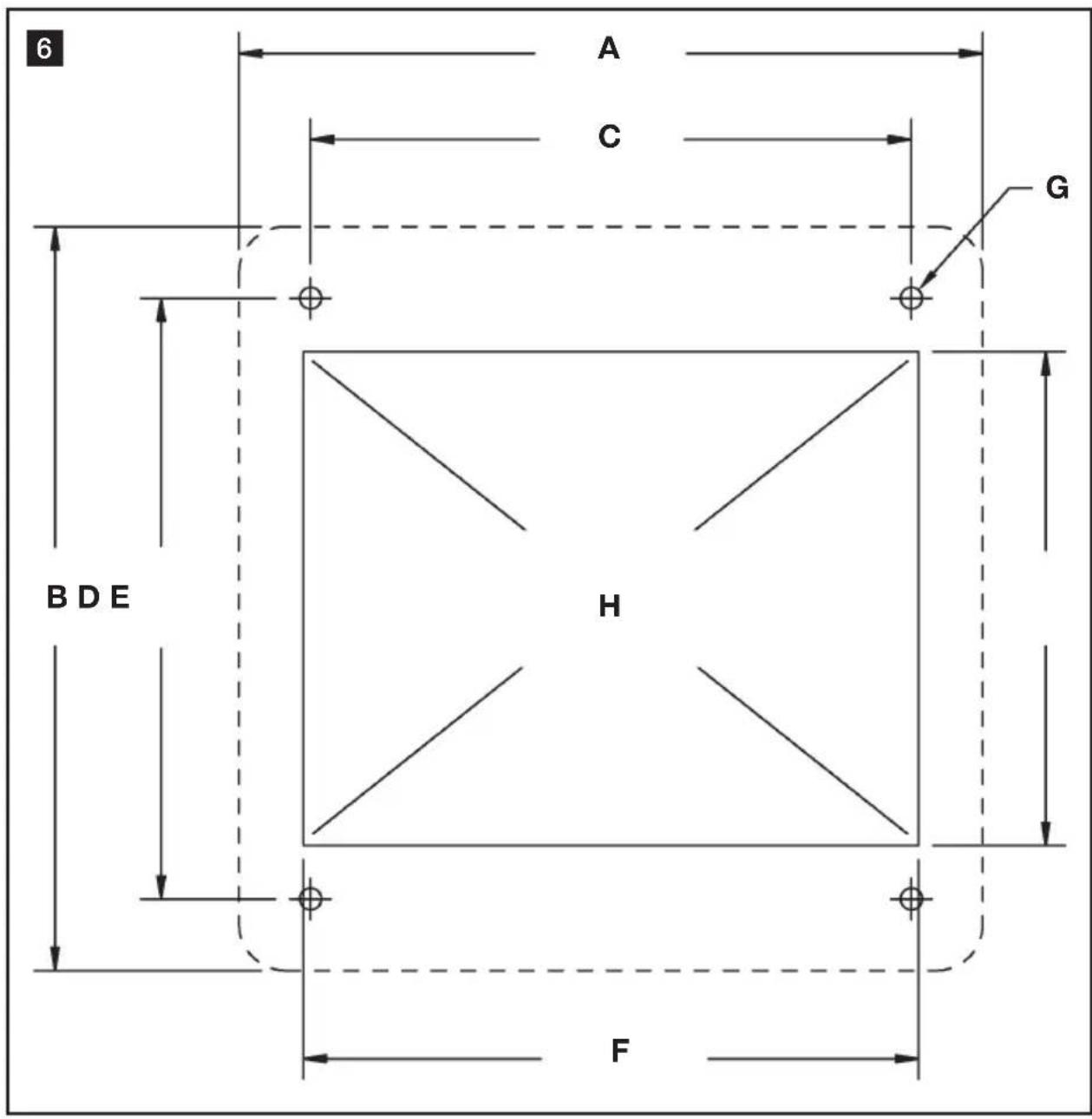
Table of contents
EN
1 Notes on using the manual 7
2 General safety instructions 7
3 Intended use 7-8
4 Components 8
5 Specifications 8-9
6 Installation 9-10
7 Operation. 11
8 Warranty and Product Liability 11-12
1 Notes on using the manual

Caution!
Safety Instruction: Failure to observe this instruction can cause material damage and impair the function of the device.

Note
Supplementary information for operating the device.
fig. 2 A, page 2: This refers to an element in an illustration. In this example, item A in figure 2 on page 2.
2 General safety instructions
The manufacturer will not be held liable for claims for damage resulting from the following:
- Faulty assembly or connection
- Damage to the unit from mechanical influences, misuse or abuse
- Float switches fouled with tissue paper
- Alterations to the unit without express written permission from the manufacturer
- Use for purposes other than those described in this manual
3 Intended use
3.1 OPTION 1: DTM04 tank monitor system
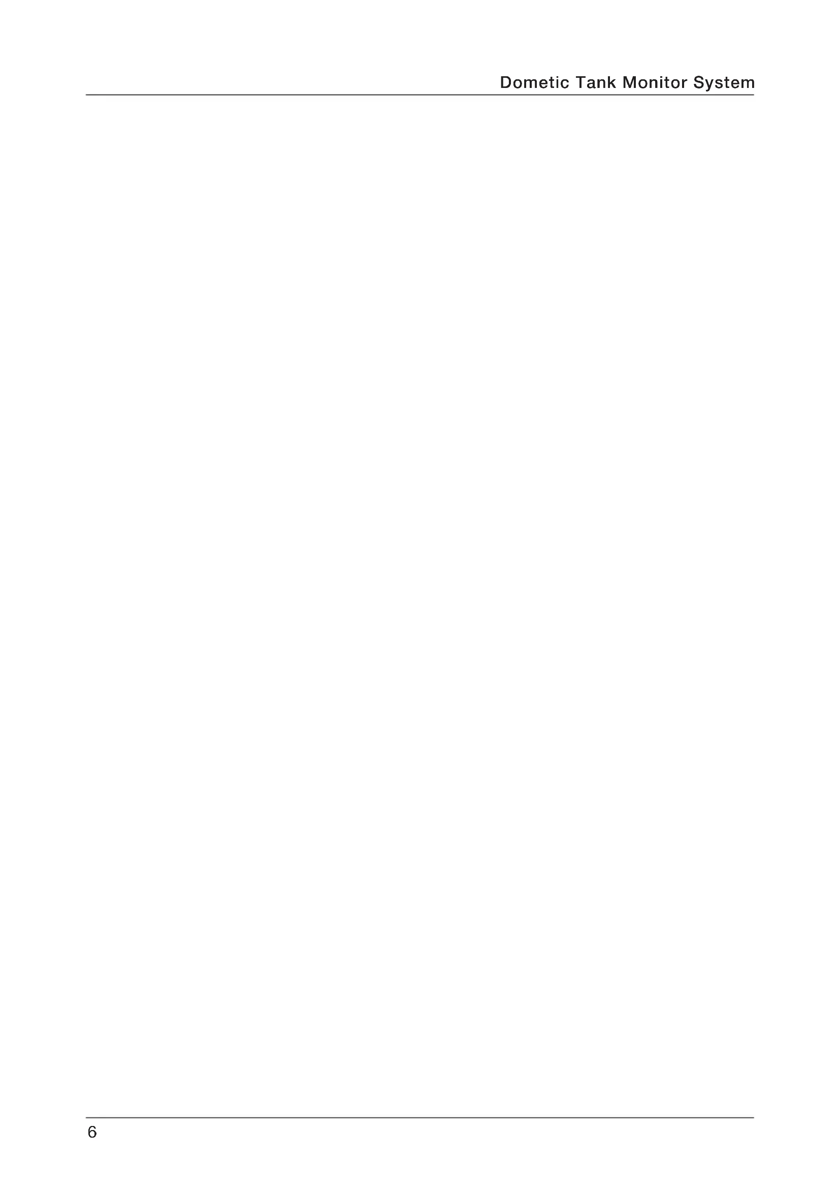
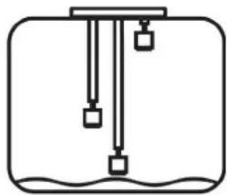
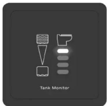
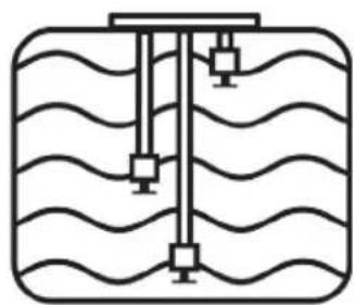
DTM04 Tank Monitor System provides electronic monitoring of the liquid level inside a holding tank. Three float switches inside the tank activate a set of four lights on an indicator panel. The lights indicate Empty, Low, Mid and Full levels. The Full level indicates when the liquid level is within 51 mm (2 in.) of the top of the holding tank. The other float switches are connected to adjustable probe stems which can be positioned according to the tank height and the desired indicator panel readings.
3.2 OPTION 2: DTM04 tank monitor system with "full tank" shut-down relay
When the optional "Full Tank" Shut-down Relay (available separately) is connected to the DTM04 panel, and the holding tank reaches the Full level, the relay shuts off power to the electric toilet. This prevents use of the toilet and the possibility of overfilling the holding tank. See Components for "Full Tank" Shutdown Relay item numbers. The relay handles a maximum electrical current of 30 amps.
3.3 Features
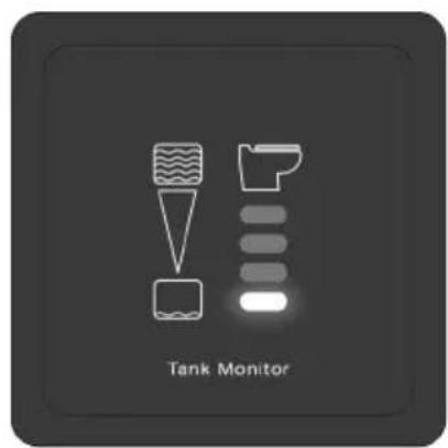
"Power on" indicator. One Tank Monitor panel light is always lit to assure system operation.
Long-lasting, foul-proof tank probes. Semi-flexible probe stems move with tank contents to reduce stress. Integral sensor delay prevents false readings.
Probe cap fits Dometic DHT-L series holding tanks. Also fits other tanks equipped with 76 mm (3 in.) NPT opening in top of tank.
For holding tanks up to 56 cm (22 in.) deep. Flexible probes can be adjusted to fit many tank sizes.
12 or 24 V DC operation.
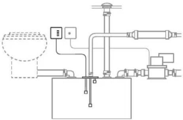
4 Components
Itemsinfig.
1 page 2
Description Item Number (Europe / North America)
1DTM04coverpanel860003853114778/385311477
DTM04 circuit panel/ 860003853114836 / 385311483 mounting frame
3#6fastener860003853116120/385311612
4 "Full Tank" shut-down relay 9107100013 / 385311579 - 12 V DC (available separately) 9107100014 / 385311580 - 24 V DC
5 Compression nut kit 860003853102583 / 385310258
6 Float/stem kit 860003852302689 / 385230268
7 Float/lock ring kit 860003853111030 / 385311103
8 Flexible probe kit 860003852309304 / 385230930
9 O-ring 860003853112509 / 385311250
10 Probe cap/O-ring 860003853116179 / 385311617
5 Specifications
5.1 Materials
Panel frame and mounting frame: ABS
Panel surface: Polycarbonate resin
Probe cap: PVC
Floats: Nitrile rubber ebonite
5.2 Electrical Current Draw
System Voltage Amp
12 V DC
without shut-down relay
with shut-down relay
0.008
0.145
24 V DC
without shut-down relay
with shut-down relay
0.004
0.090
Specifications subject to change without notice.
Circuit breaker or fuse
required for DTM04 panel:
1 amp
Maximum shut-down relay
rating for 12 or 24 V DC
toilet system:
30 amps
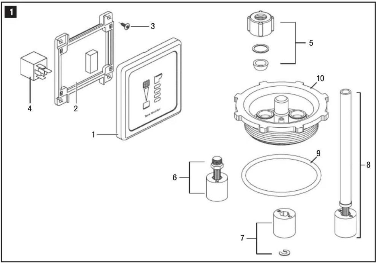
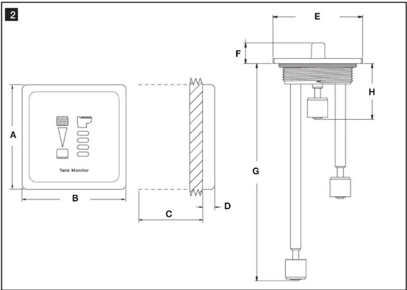
5.3 Dimensions (fig. 2, page 2)
Ref. Dimension
A 83mm / 3.25 in.
B 83mm / 3.25 in.
C 51mm / 2 in. clearance behind wall
D 10mm / 0.38 in.
Ref. Dimension
E 111 mm / 4.375 in.
F 25mm / 1.0 in.
G 527 mm / 20.75 in.
H 69 mm / 2.75 in.
5.4 Approvals
ISO 8846; EMC Directive 2004/108/EC
6 Installation
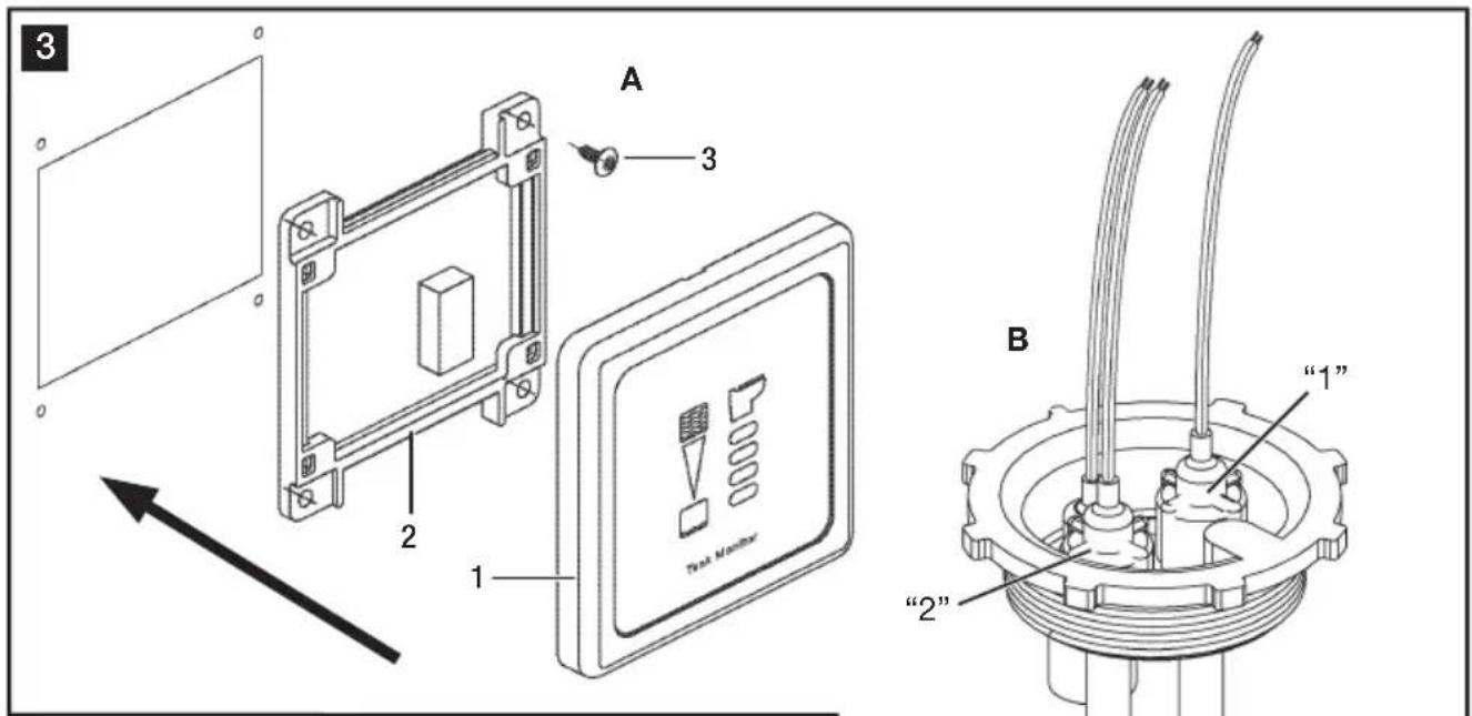
6.1 Tank Monitor Panel (fig. 3 A, page 2)

Caution!
Do not install DTM04 panel in an atmosphere with potentially flammable or explosive vapors.
- Select panel location away from direct contact with water and oil.
- Confirm clearance for wire connections behind wall, hull liner or bulkhead.
- Using control panel template (fig. 6, page 5), cut out panel access hole (E, F) and drill fastener holes (G).
- With electrical power off, route 18-gauge stranded copper wire from power source, through circuit breaker or fuse (not provided), to panel location. Route additional wire according to diagram (fig. 4, page 3 - see wiring diagram key below), depending on your application, to panel location. Make sure wires extend out through access hole.
- Make proper wiring connections to wires extending from bottom of circuit panel (fig. 3 A 2, page 3).
- Remove panel cover (fig. 3A 1, page 3) from circuit panel/ mounting frame (A 2), if necessary, by carefully pulling them apart.
- Install mounting frame to wall with four fasteners (fig. 3A 3).
- Push panel cover onto mounting frame until it locks into place.
DTM04 Panel Template
Dimensions (fig. 6, page 5)
Ref. Dimension
A 83mm / 3.25 in.
B 83mm / 3.25 in.
C 67~mm /2.63 in,
D 67~mm /2.63 in.
E 55mm / 2.16 in.
F 68 mm / 2.69 in.
G 2 mm / 0.10 in. dia.
H Cut-out area.
Allow 51mm / 2 in. clearance behind wall.
6.2 "Full Tank" Shut-down Relay (optional accessory) (fig. 1 4, page 2)
- At step 4 (above), route and connect 14-gauge stranded copper wires according to wiring diagram (fig. 4, page 3) and wiring diagram key (see below).
- Insert "Full Tank" shut-down relay into receptacle on back of circuit panel.
6.3 Probe Cap (fig. 3 B, page 2)

Caution!
Do not install probe cap in fuel tank. Never install Dometic probe cap with float switches into a tank that contains anything other than waste water, grey water or fresh water.
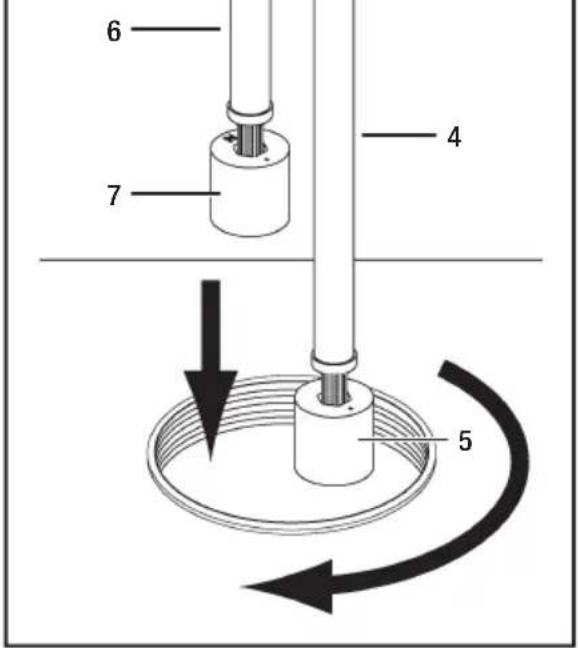
- Loosen compression nuts on adjustable probes and install probe cap into tank. Following numbers printed on top of probe cap, slide the "1" probe (fig. 3 B 4, page 3) down until the float touches the bottom of the tank. Tighten "1" compression nut and mark the probe tube at the top of the nut. Do not cut the probe tube at this mark. Loosen the compression nut, slide the probe up, and carefully cut the "1" probe tube 42mm (1.625 inches) below the mark without damaging the wires inside the tube. Pull the wires through the black wire cover and push the probe down into the compression nut until the black wire cover touches the compression nut. The recessed shoulder of the float, or the letters "NO", should be facing down (B 5).
- Remove probe cap from tank and adjust the "2" probe (fig. 3 B 6, page 3) for one-half full level for black or gray water tanks. Tighten the compression nut and cut the probe tube off 10mm (0.375 inch) above the compression nut without damaging the wires. Slip the black wire cover onto the top of the tube. The recessed shoulder of the float, or the letters "NO", should be facing up (B 7).
- Route 18-gauge stranded copper wires from monitor panel and DC ground source to the probe cap. Use quick-disconnect terminals on float switch wires to prevent twisting wires when removing the cap. With cap removed from tank, connect the wires according to the wiring diagram (fig. 4, page 3), turn on electrical power to system, and test the floats by moving them up and down and monitoring the DTM04 panel. Disconnect the wires and install the probe cap and O-ring into the tank. Reconnect the wires.
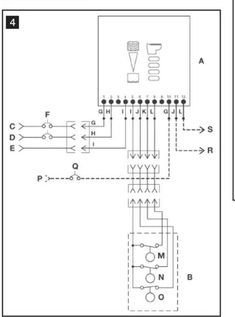
6.4 Key to DTM04 system wiring (fig. 4, page 3)
Ref. Description
A DTM04 indicator panel
B Wastewater tank
C 12 V DC
D 24 V DC
E V DC ground
F 1-amp circuit breaker or fuse
G Red
H Blue
I Black
J Green
K Yellow
L Orange
M Full level probe
Ref. Description
N Mid level probe
O Low/Empty level probe
P 12 or 24 V DC
Q Toilet system circuit breaker or fuse
R + VDC to electric toilet system
S + V DC to "full tank" monitor (optional)
Notes:
- Heavy line indicates 14 gauge or larger stranded copper wire is required.
- Other wire can be 18 gauge stranded copper wire or larger.

Caution!
Operator must know local regulations for emptying a holding tank.
7 Operation
7.1 OPTION 1: DTM04 tank monitor system only (fig. 5, page 4)
- When contents inside holding tank is below lowest level float switch (1), the green "Empty" indicator light of the Dometic Tank Monitor indicator panel is on.
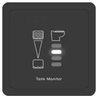
- When holding tank contents rises above the lowest level float switch (2), but is below the middle level float switch, the yellow "Low" light turns on, and the "Empty" light turns off.
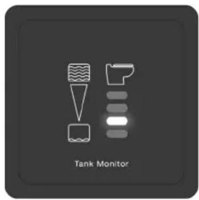
- When holding tank contents rises above the middle level float (3), but is below the high level float switch, the amber "Mid" light turns on, and the "Low" light turns off.
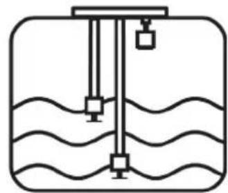
- When holding tank contents rises to the high level float (4), the amber "Full" light turns on, indicating that it is time to pump-out the holding tank. The toilet system should not be used until the holding tank is pumped out to avoid potential damage that may occur due to overfilling the holding tank.
7.2 OPTION 2: DTM04 tank monitor system with "full tank" shut-down relay (fig. , pa54)
- When the Dometic Tank Monitor panel reads "Full" (4), electrical power to the toilet system will be automatically turned off to prevent possible overfilling of the holding tank.
- Electrical power is restored to the toilet system when the "Full" level indicator light turns off during pump-out.
8 Warranty and Product Liability
Europe:
Warranty and Customer Service
Warranty arrangements are in accordance with EC Directive 44/1999/CE and the normal conditions applicable for the country concerned. For warranty or other service, please contact our Domatic/Waeco Service department listed elsewhere in this manual. Any damage due to improper use is not covered by the warranty.
The warranty does not cover any modifications to the product or the use of non-original Dometic parts; the warranty does not apply if the installation and operating instructions are not adhered to and no liability shall be entertained.
Product Liability
Product liability of Dometic Group and its subsidiary companies does not include damages which may arise from: faulty operation; improper alterations or intervention in the equipment; adverse effects from the environment which may impact the equipment itself or the direct vicinity of the equipment or persons in the area.
To obtain warranty service, first contact your local dealer from whom you purchased this product or go to http://www.dometic.com for a dealer near you.
North America and Rest of the World:
Manufacturer's One-Year and Five-Year Limited Warranty
Dometic Corporation, Sanitation Division warrants to the original purchaser only that this product, if used for personal, family or household purposes, is free from defects in material and workmanship for a period of one year from the date of purchase.
If this Dometic product is placed in commercial or business use, it will be warranted to the original purchaser only to be free of defects in material and workmanship for a period of ninety (90) days from the date of purchase.
Domatic reserves the right to replace or repair any part of this product that proves, upon inspection by Domatic, to be defective in material or workmanship. All labor and transportation costs or charges incidental to warranty service are to be borne by the purchaser-user.
EXCLUSIONS
IN NO EVENT SHALL DOMETIC BE LIABLE FOR INCIDENTAL OR CONSEQUENTIAL DAMAGES, FOR DAMAGES RESULTING FROM IMPROPER INSTALLATION, OR FOR DAMAGES CAUSED BY NEGLECT, ABUSE, ALTERATION OR USE OF UNAUTHORIZED COMPONENTS. ALL IMPLIED WARRANTY, INCLUDING ANY IMPLIED WARRANTY OF MERCHANTABILITY OR FITNESS FOR ANY PARTICULAR PURPOSE, ARE LIMITED TO A PERIOD OF ONE YEAR FROM DATE OF PURCHASE.
IMPLIED WARRANTYIS
No person is authorized to change, add to, or create any warranty or obligation other than that set forth herein. Implied warranties, including those of merchantability and fitness for a particular purpose, are limited to one (1) year from the date of purchase for products used for personal, family or household purposes, and ninety (90) days from the date of purchase for products placed in commercial or business use.
OTHER RIGHTS
Some states do not allow limitations on the duration of an implied warranty and some states do not allow exclusions or limitations regarding incidental or consequential damages; so, the above limitations may not apply to you. This warranty gives you specific legal rights, and you may have other rights which vary from state to state.
To obtain warranty service, first contact your local dealer from whom you purchased this product or go to http://www.dometic.com/enus/Americas/USA/Customer-Support/ for a dealer near you.
Registered; TM Trademark of Dometic Corporation
Inhalt
DE
Ref. Abmessungen mm / Zoll
A 83 / 3,25
Ref. Abmessungen mm / Zoll
E 111/4,375
B 83 / 3,25
F 25 / 1,0
Vlotters: hard nitrilrubber
Systeemstroom ampere
12 V DC
zonderafsluitrelais
met afsluitrelais
0,008
0,145
24VDC
zonder afluitrelais
met afsluitrelais
0,004
0,090
Specifications können onaangekondigd veranderen.
Mall for DTM04 panel
(bild 6, sida 5)
Ref. Dimensioner
A 83mm / 3,25 in.
B 83mm / 3,25 in.
C 67~mm / 2,63 in.
D 67mm / 2,63 in.
E 55mm / 2,16 in.
F 68~mm / 2,69 in.
G 2 mm / 0,10 in. dia.
H 51 mm/2 in. tritt utrymme bakom vaggen
Dometic Australia Pty. Ltd.
1 John Duncan Court
Varsity Lakes QLD 4227
Tel +61 7 55076000
Fax +61755076001
Mail sales@dometic-waeco.
com.au
FRANCE
Dometic S.N.C.
Dometic Poland Sp. z o.o.
ul. Puławska 435A
PL-02-801 Warszawa
Tel +48 22 414 32 00
Fax +48 22 414 32 01
Mail info@dometic.pl
SWITZERLAND
Domatic Switzerland AG
Riedackerstrasse 7a
CH-8153 Rumiang
Tel +41 44 8187171
Fax +41 44 8187191
Mail info@
dometic-waeco.ch
BENELUX
Dometic Benelux B.V.
Ecustraat 3
NL-4879 NP Etten-Leur
Tel +31 76 5029000
Fax +31 76 5029090
Mail info@dometic.nl
Dometic Branch Office
Belgium
Zinkstraat 13
B-1500 Halle
Tel +32 2 3598040
Fax +32 2 3598050
Mail info@dometic.be
CHINA
WAECO Impex Ltd.
Shenzhen Futian office (WIE)
1402-1404 1 D/F
Zhou Yue Building
Fu Hua Road,
Futian Central Zone
518048 Shenzhen
Tel +86 755 2560 7722
DENMARK
Dometic Denmark A/S
Nordensvej 15, Taulov
DK-7000 Fredericia
Tel +45 75585966
Fax +45 75586307
Mail info@waeco.dk
FINLAND
Dometic Finland OY
Mestarintie 4
FIN-01730 Vantaa
Tel +358 20 7413220
Fax +358 9 7593700
Mail info@dometic.fi
HONG KONG
Domatic Group Asia Pacific
Suites 2207-11·22/F·
Tower 1
The Gateway 25 Canton
Road
Tsim Sha Tsui · Kowloon
Tel +852 2 4611386
Fax +852 2 4665553
Mail info@waeco.com.hk
ITALY
Domatic Italy S.p.A.
Via Gazzani, 8/2
Dometic New Zealand Ltd.
26 Cashew Street
NZ-Grenada North
Wellington 6440
Tel +64 4 232 3898
Fax +64 4 232 3878
Mail customerservices@
dometic.com.nz
SINGAPORE
Dometic Pte Ltd
18 Boon Lay Way 06-140
Trade Hub 21
Singapore 609966
Tel +65 6795 3177
Fax +65 6862 6620
Mail dometic@dometic.com.
sg
SLOVAKIA
Dometic Slovakia s.r.o
Tehelna 8
SK-98601 Filakovo
Tel +421 47 4319 100
Fax +421 47 4319 144
Mail dometic@dometic.sk
SOUTH AFRICA
Dometic (Pty) Ltd.
Regional Office
South Africa & Sub-Saharan
Africa
P.O.Box 2562
2008 Bedfordview
Tel +27 11 4504978
Fax +27 11 4504976
Mail info@dometic.coM.za
SPAIN
Dometic Spain S.L.
Avda. Sierra del
Guadarrama, 16
E-28691 Villanueva de la
Canada · Madrid
Tel +34 902 111 042
Fax +34 900 100 245
Mail info@dometic.es
UNITED ARAB EMIRATES
Dometic AB
Regional Office Middle East
PO Box 74775
Dubai
Tel +97143212160
Tel +97148833858
Mail info@dometic.ae
USA
Dometic Marine Division
2000 N. Andrews Ave. Ext.
Pompano Beach, FL 33069
Tel +954-973-2477
Fax +954-979-4414
Mail marinesales@
dometic.com

- Table of contents
- EN
- Notes on using the manual
- Caution!
- Note
- General safety instructions
- Intended use
- OPTION 1: DTM04 tank monitor system
- OPTION 2: DTM04 tank monitor system with "full tank" shut-down relay
- Features
- Components
- Specifications
- Materials
- Electrical Current Draw
- Dimensions (fig. 2, page 2)
- Approvals
- Installation
- Tank Monitor Panel (fig. 3 A, page 2)
- DTM04 Panel Template
- Dimensions (fig. 6, page 5)
- "Full Tank" Shut-down Relay (optional accessory) (fig. 1 4, page 2)
- Probe Cap (fig. 3 B, page 2)
- Key to DTM04 system wiring (fig. 4, page 3)
- Ref. Description
- Notes:
- Operation
- OPTION 1: DTM04 tank monitor system only (fig. 5, page 4)
- OPTION 2: DTM04 tank monitor system with "full tank" shut-down relay (fig. , pa54)
- Warranty and Product Liability
- Europe:
- Warranty and Customer Service
- Product Liability
- North America and Rest of the World:
- Manufacturer's One-Year and Five-Year Limited Warranty
- EXCLUSIONS
- IMPLIED WARRANTYIS
- OTHER RIGHTS
- Inhalt
- DE
- Mall for DTM04 panel
- Ref. Dimensioner
- FRANCE
- SWITZERLAND
- BENELUX
- Dometic Branch Office
- CHINA
- DENMARK
- FINLAND
- HONG KONG
- ITALY
- SINGAPORE
- SLOVAKIA
- SOUTH AFRICA
- SPAIN
- UNITED ARAB EMIRATES
- Dometic AB
- USA
Brand : DOMETIC
Model : DTM04
Category : Toilet