USER MANUAL B360MHDV ASROCK
Published February 2018
Copyright ©2018 ASRock INC. All rights reserved.
Copyright Notice:
No part of this documentation may be reproduced, transcribed, transmitted, or translated in any language, in any form or by any means, except duplication of documentation by the purchaser for backup purpose, without written consent of ASRock Inc.
Products and corporate names appearing in this documentation may or may not be registered trademarks or copyrights of their respective companies, and are used only for identification or explanation and to the owners' benefit, without intent to infringe.
Disclaimer:
Specifications and information contained in this documentation are furnished for informational use only and subject to change without notice, and should not be constructed as a commitment by ASRock. ASRock assumes no responsibility for any errors or omissions that may appear in this documentation.
With respect to the contents of this documentation, ASRock does not provide warranty of any kind, either expressed or implied, including but not limited to the implied warranties or conditions of merchantability or fitness for a particular purpose.
In no event shall ASRock, its directors, officers, employees, or agents be liable for any indirect, special, incidental, or consequential damages (including damages for loss of profits, loss of business, loss of data, interruption of business and the like), even if ASRock has been advised of the possibility of such damages arising from any defect or error in the documentation or product.

This device complies with Part 15 of the FCC Rules. Operation is subject to the following two conditions:
(1) this device may not cause harmful interference, and
(2) this device must accept any interference received, including interference that may cause undesired operation.
CALIFORNIA, USA ONLY
The Lithium battery adopted on this motherboard contains Perchlorate, a toxic substance controlled in Perchlorate Best Management Practices (BMP) regulations passed by the California Legislature. When you discard the Lithium battery in California, USA, please follow the related regulations in advance.
"Perchlorate Material-special handling may apply, see www.dtsc.ca.gov/hazardouswaste/perchlorate"
ASRock Website: http://www.asrock.com

AUSTRALIA ONLY
Our goods come with guarantees that cannot be excluded under the Australian Consumer Law. You are entitled to a replacement or refund for a major failure and compensation for any other reasonably foreseeable loss or damage caused by our goods. You are also entitled to have the goods repaired or replaced if the goods fail to be of acceptable quality and the failure does not amount to a major failure. If you require assistance please call ASRock Tel: +886-2-28965588 ext.123 (Standard International call charges apply)
The terms HDMI^※ and HDMI High-Definition Multimedia Interface, and the HDMI logo are trademarks or registered trademarks of HDMI Licensing LLC in the United States and other countries.

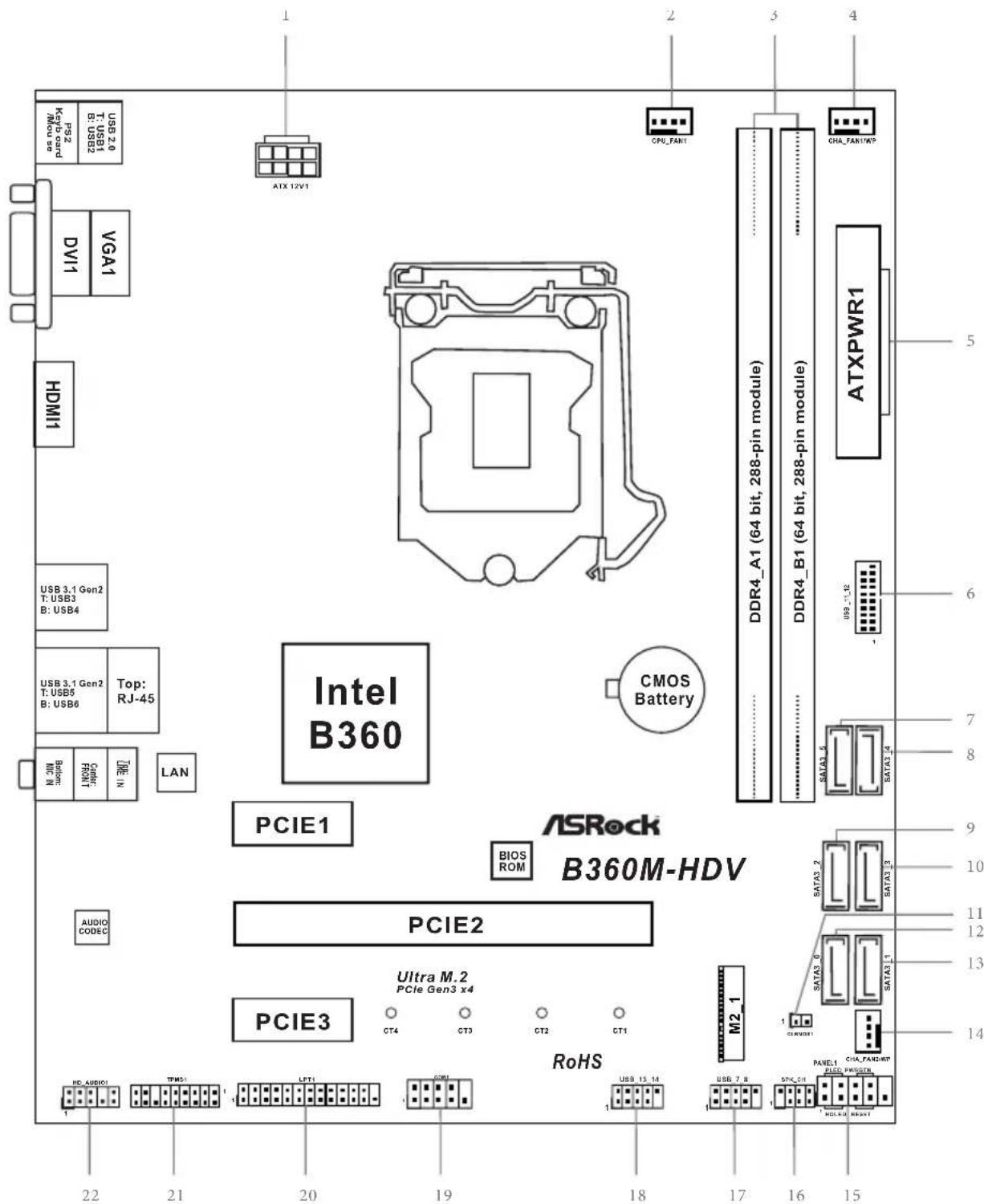
Motherboard Layout
No. Description
1ATX 12V Power Connector (ATX12V1)
2 CPU Fan Connector (CPU_FAN1)
3 2 x 288-pin DDR4 DIMM Slots (DDR4_A1, DDR4_B1)
4 Chassis/Water Pump Fan Connector (CHA_FAN1/WP)
5 ATX Power Connector (ATXPWR1)
6 USB 3.1 Gen1 Header (USB_11_12)
7 SATA3 Connector (SATA3_5)
8 SATA3 Connector (SATA3_4)
9 SATA3 Connector (SATA3_2)
10 SATA3 Connector (SATA3_3)
11 Clear CMOS Jumper (CLRMOS1)
12 SATA3 Connector (SATA3_0)
13 SATA3 Connector (SATA3_1)
14 Chassis/Water Pump Fan Connector (CHA_FAN2/WP)
15 System Panel Header (PANEL1)
16 Chassis Intrusion and Speaker Header (SPK_CII)
17 USB 2.0 Header (USB_7_8)
18 USB 2.0 Header (USB_13_14)
19 COM Port Header (COM1)
20 Print Port Header (LPT1)
21 TPM Header (TPMS1)
22 Front Panel Audio Header (HD_AUDIO1)
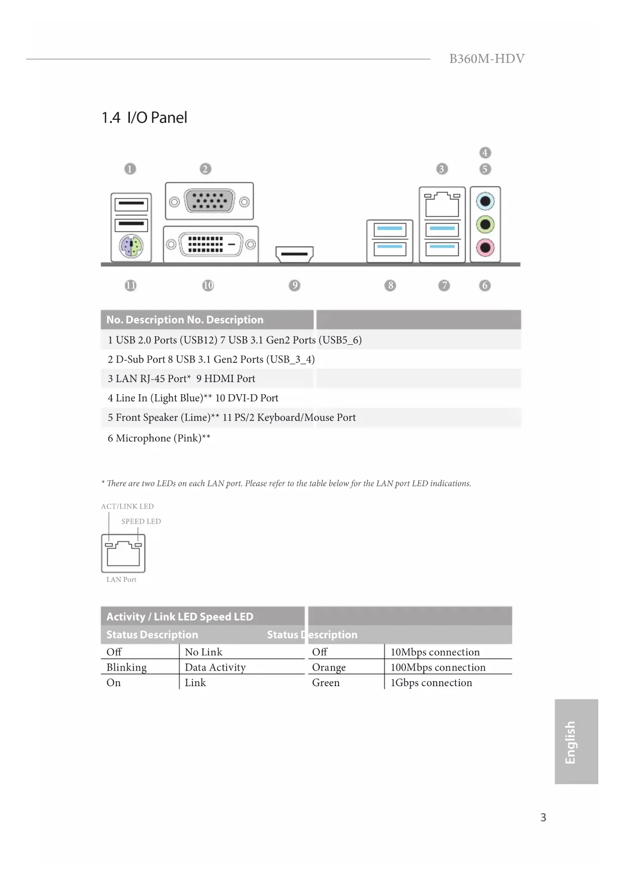
1.4 I/O Panel
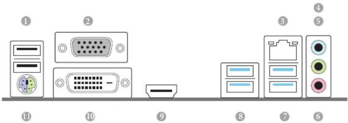
No. Description No. Description
1 USB 2.0 Ports (USB12) 7 USB 3.1 Gen2 Ports (USB5_6)
2 D-Sub Port 8 USB 3.1 Gen2 Ports (USB_3_4)
3 LAN RJ-45 Port 9 HDMI Port
4 Line In (Light Blue)** 10 DVI-D Port
5 Front Speaker (Lime)* 11 PS/2 Keyboard/Mouse Port
6 Microphone (Pink)**
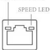
ACT/LINK LED
LAN Port
| Activity / Link LED Speed LED | | |
| Status Description Status Description |
| Off | No Link | Off | 10Mbps connection |
| Blinking | Data Activity | Orange | 100Mbps connection |
| On | Link | Green | 1Gbps connection |
** To configure 7.1 CH HD Audio, it is required to use an HD front panel audio module and enable the multichannel audio feature through the audio driver.
Please set Speaker Configuration to "7.1 Speaker" in the Realtek HD Audio Manager.
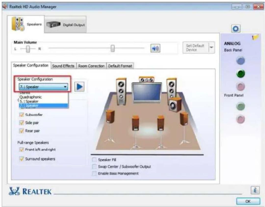
Function of the Audio Ports in 7.1-channel Configuration:
Port Function
| Light Blue (Rear panel) Rear Speaker Out |
| Lime (Rear panel) Front Speaker Out |
| Pink (Rear panel) Central /Subwoofer Speaker Out |
| Lime (Front panel) Side Speaker Out |
Chapter 1 Introduction
Thank you for purchasing ASRock B360M-HDV motherboard, a reliable motherboard produced under ASRock's consistently stringent quality control. It delivers excellent performance with robust design conforming to ASRock's commitment to quality and endurance.

Because the motherboard specifications and the BIOS software might be updated, the content of this documentation will be subject to change without notice. In case any modifications of this documentation occur, the updated version will be available on ASRock's website without further notice. If you require technical support related to this motherboard, please visit our website for specific information about the model you are using. You may find the latest VGA cards and CPU support list on ASRock's website as well. ASRock website http://www.asrock.com.
1.1 Package Contents
ASRock B360M-HDV Motherboard (Micro ATX Form Factor)
ASRock B360M-HDV Quick Installation Guide
ASRock B360M-HDV Support CD
1 x I/O Panel Shield
2 x Serial ATA (SATA) Data Cables (Optional)
1 x Screw for M.2 Socket (Optional)
1.2 Specifications
| Platform | Micro ATX Form Factor
Solid Capacitor design |
| CPU | Supports 8thGeneration Intel® Core™ Processors (Socket 1151)
Supports Intel® Turbo Boost 2.0 Technology |
| Chipset | Intel® B360 |
| Memory | Dual Channel DDR4 Memory Technology
2 x DDR4 DIMM Slots
Supports DDR4 2666/2400/2133 non-ECC, un-buffered memory
Max. capacity of system memory: 32GB
Supports Intel® Extreme Memory Profile (XMP) 2.0
15μ Gold Contact in DIMM Slots |
| Expansion Slot | 1 x PCI Express 3.0 x16 Slot (PCIE1: x16 mode)*
* Supports NVMe SSD as boot disks
2 x PCI Express 3.0 x1 Slots (Flexible PCIe) |
| Graphics | Intel® UHD Graphics Built-in Visuals and the VGA outputs can be supported only with processors which are GPU integrated.
Supports Intel® UHD Graphics Built-in Visuals : Intel®
Quick Sync Video with AVC, MVC (S3D) and MPEG-2 Full HW Encode1, Intel® InTru™ 3D, Intel® Clear Video HD Technology, Intel® Insider™, Intel® UHD Graphics DirectX 12
HwAEncode/Decode: AVC/H.264, HEVC/H.265 8-bit, HEVC/H.265 10-bit, VP8, VP9 8-bit, VP9 10-bit (Decode only), MPEG2, MJPEG, VC-1 (Decode only) |
Three graphics output options: D-Sub, DVI-D and HDMI
Supports HDMI with max. resolution up to 4K× 2K
(4096x2160) @ 30Hz
Supports DVI-D with max. resolution up to 1920x1200 @ 60Hz
Supports D-Sub with max. resolution up to 1920x1200 @ 60Hz
Supports Auto Lip Sync, Deep Color (12bpc), xvYCC and
HBR (High Bit Rate Audio) with HDMI Port (Compliant HDMI monitor is required)
Supports HDCP with DVI-D and HDMI Ports
Supports 4K Ultra HD (UHD) playback with HDMI Port
Audio
7.1 CH HD Audio (Realtek ALC887 Audio Codec)
- To configure 7.1 CH HD Audio, it is required to use an HD front panel audio module and enable the multi-channel audio feature through the audio driver.
Supports Surge Protection
ELNA Audio Caps
LAN
Gigabit LAN 10/100/1000 Mb/s
Giga PHY Intel® I219V
Supports Wake-On-LAN
Supports Lightning/ESD Protection
Supports Energy Efficient Ethernet 802.3az
Supports PXE
Rear Panel
1xPS/2 Mouse/Keyboard Port
I/O
1xD-SubPort
1xDVI-DPort
1xHDMIPort
2 x USB 2.0 Ports (Supports ESD Protection)
4xUSB3.1 Gen2 Type-A Ports (10 Gb/s)
1 x RJ-45 LAN Port with LED (ACT/LINK LED and SPEED LED)
HD Audio Jacks: Line in / Front Speaker / Microphone
Storage
6 x SATA3 6.0 Gb/s Connectors, support NCQ, AHCI and Hot Plug*
- If M2_1 is occupied by a SATA-type M.2 device, SATA3_3 will be disabled.
1 x Ultra M.2 Socket (M2_1), supports M Key type
2230/2242/2260/2280 M.2 SATA3 6.0 Gb/s module and M.2 PCI Express module up to Gen3 x4 (32 Gb/s)**
**Supports Intel OptaneTM Technology
Supports NVMe SSD as boot disks
Supports ASRock U.2 Kit
Connector
1 x Print Port Header
1xCOMPortHeader
1xTPMHeader
1 x Chassis Intrusion and Speaker Header
1 x CPU Fan Connector (4-pin)
- The CPU Fan Connector supports the CPU fan of maximum 1A (12W) fan power.
2 × Chassis/Water Pump Fan Connectors (4-pin) (Smart Fan Speed Control)
1 x 24 pin ATX Power Connector
1 x 8 pin 12V Power Connector
1 x Front Panel Audio Connector
2 x USB 2.0 Headers (Support 4 USB 2.0 ports) (Supports ESD Protection)
1 x USB 3.1 Gen1 Header (Supports 2 USB 3.1 Gen1 ports) (Supports ESD Protection)
BIOS
AMI UEFI Legal BIOS with multilingual GUI support
Feature
ACPI 6.0 Compliant wake up events
SMBIOS 2.7 Support
CPU, GT_CPU, DRAM, PCH 1.05V Voltage Multi-adjustment
Hardware
Temperature Sensing: CPU, Chassis/Water Pump Fans
Monitor
Fan Tachometer: CPU, Chassis/Water Pump Fans
Quiet Fan (Auto adjust chassis fan speed by CPU temperature):CPU,Chassis/Water Pump Fans Fan Multi-Speed Control:CPU,Chassis/Water Pump Fans CASE OPEN detection Voltage monitoring: +12V, + 5V, + 3.3V ,CPU Vcore,DRAM, PCH 1.05V
os
Microsoft Windows 10 64-bit
Certifications
FCC, CE ErP/EuP ready (ErP/EuP ready power supply is required)
- For detailed product information, please visit our website: http://www.asrock.com

Please realize that there is a certain risk involved with overclocking, including adjusting the setting in the BIOS, applying Untied Overclocking Technology, or using third-party overclocking tools. Overclocking may affect your system's stability, or even cause damage to the components and devices of your system. It should be done at your own risk and expense. We are not responsible for possible damage caused by overclocking.
Chapter 2 Installation
This is a Micro ATX form factor motherboard. Before you install the motherboard, study the configuration of your chassis to ensure that the motherboard fits into it.
Pre-installation Precautions
Take note of the following precautions before you install motherboard components or change any motherboard settings.
Make sure to unplug the power cord before installing or removing the motherboard components. Failure to do so may cause physical injuries and damages to motherboard components.
In order to avoid damage from static electricity to the motherboard's components, NEVER place your motherboard directly on a carpet. Also remember to use a grounded wrist strap or touch a safety grounded object before you handle the components.
Hold components by the edges and do not touch the ICs.
Whenever you uninstall any components, place them on a grounded anti-static pad or in the bag that comes with the components.
When placing screws to secure the motherboard to the chassis, please do not overtighten the screws! Doing so may damage the motherboard.
2.1 Installing the CPU

- Before you insert the 1151-Pin CPU into the socket, please check if the PnP cap is on the socket, if the CPU surface is unclean, or if there are any bent pins in the socket. Do not force to insert the CPU into the socket if above situation is found. Otherwise, the CPU will be seriously damaged.
- Unplug all power cables before installing the CPU.
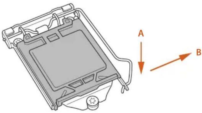
1
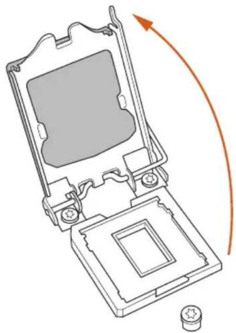
2
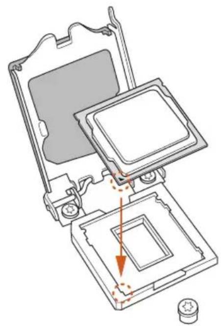
3
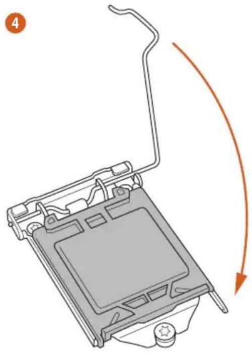
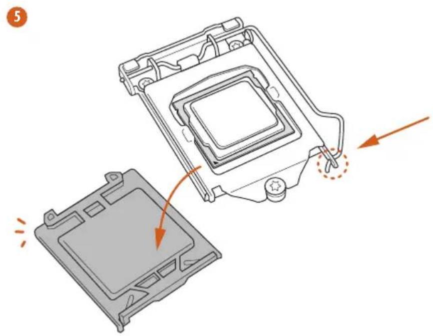

Please save and replace the cover if the processor is removed. The cover must be placed if you wish to return the motherboard for after service.
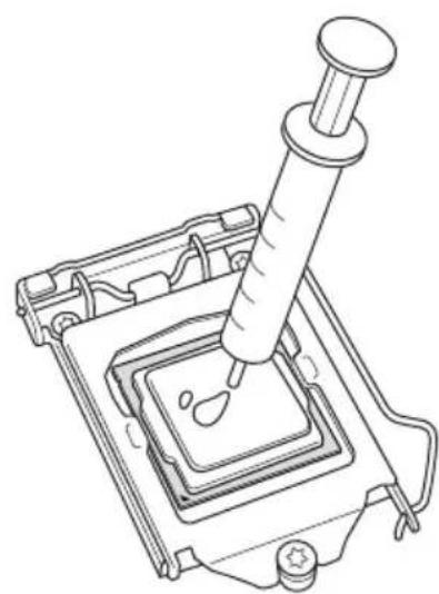
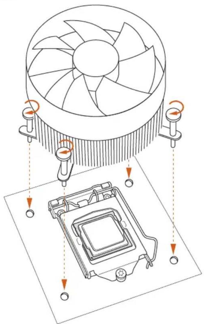
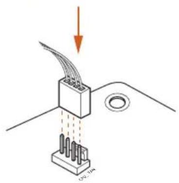
2.2 Installing the CPU Fan and Heatsink
0
2
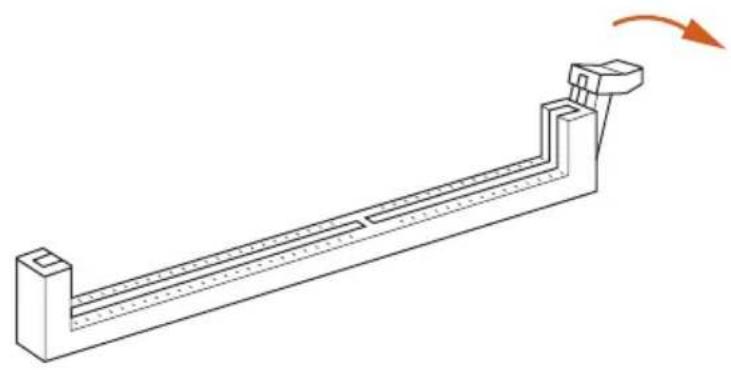
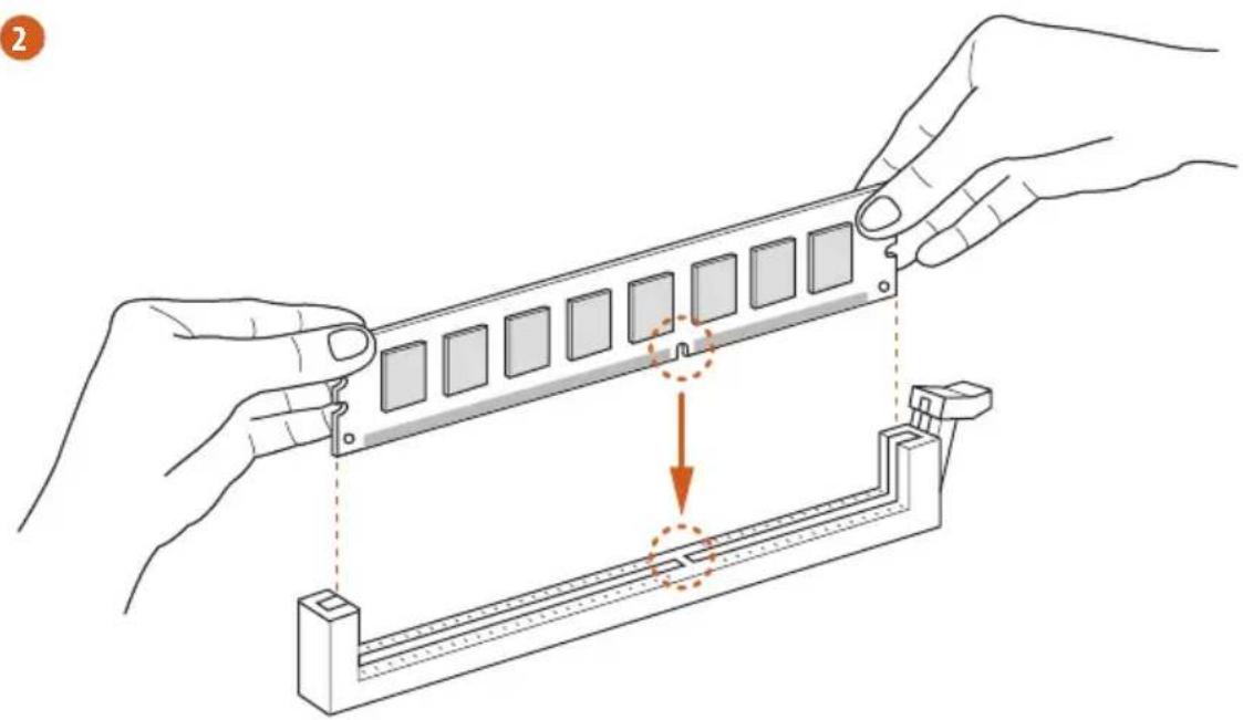
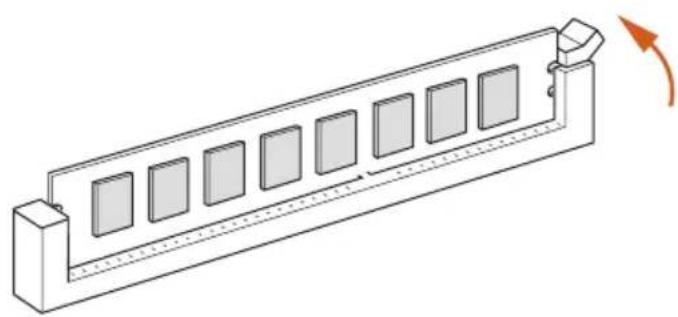
2.3 Installing Memory Modules (DIMM)
This motherboard provides two 288-pin DDR4 (Double Data Rate 4) DIMM slots, and supports Dual Channel Memory Technology.

- For dual channel configuration, you always need to install identical (the same brand, speed, size and chip-type) DDR4 DIMM pairs.
- It is unable to activate Dual Channel Memory Technology with only one memory module installed.
- It is not allowed to install a DDR, DDR2 or DDR3 memory module into a DDR4 slot; otherwise, this motherboard and DIMM may be damaged.

The DIMM only fits in one correct orientation. It will cause permanent damage to the motherboard and the DIMM if you force the DIMM into the slot at incorrect orientation.
1
2
3
2.4 Expansion Slots (PCI Express Slots)
There are 3 PCI Express slots on the motherboard.

Before installing an expansion card, please make sure that the power supply is switched off or the power cord is unplugged. Please read the documentation of the expansion card and make necessary hardware settings for the card before you start the installation.
PCIe slots:
PCIE1 (PCIe 3.0 x1 slot) is used for PCI Express x1 lane width cards.
PCIE2 (PCIe 3.0 x16 slot) is used for PCI Express x16 lane width graphics cards.
PCIE3 (PCIe 3.0 x1 slot) is used for PCI Express x1 lane width cards.
2.5 Jumpers Setup
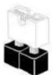
The illustration shows how jumpers are setup. When the jumper cap is placed on the pins, the jumper is "Short". If no jumper cap is placed on the pins, the jumper is "Open".

Short
Open
Clear CMOS Jumper
(CLRCMOS1)
(see p.1, No. 11)

2-pin Jumper
Short: Clear CMOS
Open: Default
CLRCMOS1 allows you to clear the data in CMOS. The data in CMOS includes system setup information such as system password, date, time, and system setup parameters. To clear and reset the system parameters to default setup, please turn off the computer and unplug the power cord, then use a jumper cap to short the pins on CLRCMOS1 for 3 seconds. Please remember to remove the jumper cap after clearing the CMOS. If you need to clear the CMOS when you just finish updating the BIOS, you must boot up the system first, and then shut it down before you do the clear-CMOS action.

If you clear the CMOS, the case open may be detected. Please adjust the BIOS option
"Clear Status" to clear the record of previous chassis intrusion status.
2.6 Onboard Headers and Connectors

Onboard headers and connectors are NOT jumpers. Do NOT place jumper caps over these headers and connectors. Placing jumper caps over the headers and connectors will cause permanent damage to the motherboard.
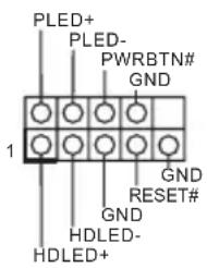
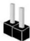
System Panel Header (9-pin PANEL1)
(see p.1, No. 15)
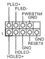
Connect the power button, reset button and system status indicator on the chassis to this header according to the pin assignments below. Note the positive and negative pins before connecting the cables.

Connect to the power button on the chassis front panel. You may configure the way to turn off your system using the power button.
Connect to the reset button on the chassis front panel. Press the reset button to restart the computer if the computer freezes and fails to perform a normal restart.
PLED (System Power LED):
Connect to the power status indicator on the chassis front panel. The LED is on when the system is operating. The LED keeps blinking when the system is in S1/S3 sleep state. The LED is off when the system is in S4 sleep state or powered off (S5).
HDLED (Hard Drive Activity LED):
Connect to the hard drive activity LED on the chassis front panel. The LED is on when the hard drive is reading or writing data.
The front panel design may differ by chassis. A front panel module mainly consists of power button, reset button, power LED, hard drive activity LED, speaker and etc. When connecting your chassis front panel module to this header, make sure the wire assignments and the pin assignments are matched correctly.
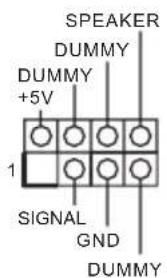
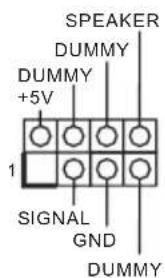
Chassis Intrusion and Speaker Header (7-pin SPK_C11) (see p.1, No. 16)

Please connect the chassis power LED and the chassis speaker to this header.
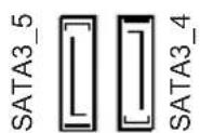
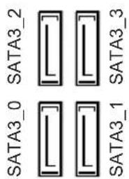
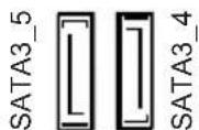
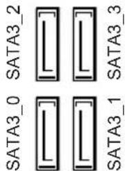
Serial ATA3 Connectors
(SATA3_0:
see p.1, No. 12)
(SATA3_1:
see p.1, No. 13)
(SATA3_2:
see p.1, No. 9)
(SATA3_3:
see p.1, No. 10)
(SATA3_4:
see p.1, No. 8)
(SATA3_5:
see p.1, No. 7)
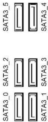
These six SATA3 connectors support SATA data cables for internal storage devices with up to 6.0 Gb/s data transfer rate. *If M2_1 is occupied by a SATA-type M.2 device, SATA3_3 will be disabled.
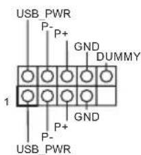
USB 2.0 Headers (9-pin USB_7_8) (see p.1, No. 17) (9-pin USB_13_14) (see p.1, No. 18)
There are two USB 2.0 headers on this motherboard. Each USB 2.0 header can support two ports.
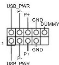
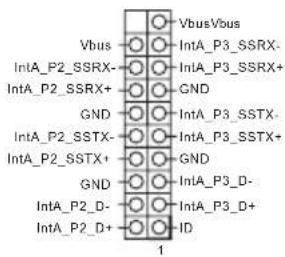
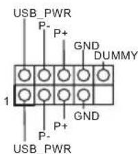
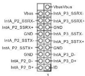
USB 3.1 Gen1 Header (19-pin USB_11_12) (see p.1, No.6)
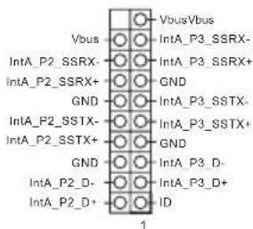
There is one header on this motherboard. This USB 3.1 Gen1 header can support two ports.
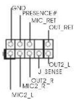
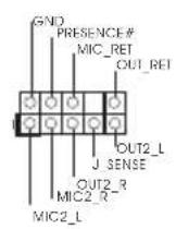
Front Panel Audio Header (9-pin HD_AUDIO1) (see p.1, No. 22)
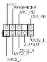
This header is for connecting audio devices to the front audio panel.

-
High Definition Audio supports Jack Sensing, but the panel wire on the chassis must support HDA to function correctly. Please follow the instructions in our manual and chassis manual to install your system.
-
If you use an AC'97 audio panel, please install it to the front panel audio header by the steps below:
A. Connect Mic_IN (MIC) to MIC2_L.
B. Connect Audio_R (RIN) to OUT2_R and Audio_L (LIN) to OUT2_L.
C. Connect Ground (GND) to Ground (GND).
D. MIC_RET and OUT_RET are for the HD audio panel only. You don't need to connect them for the AC'97 audio panel.
E. To activate the front mic, go to the "FrontMic" Tab in the Realtek Control panel and adjust "Recording Volume".
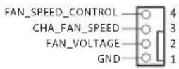
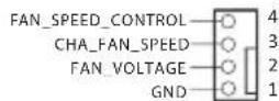
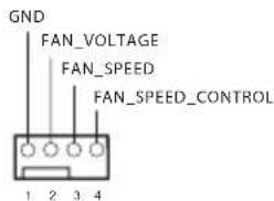
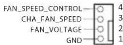
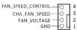
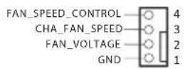
Chassis/Water Pump Fan Connectors (4-pin CHA_FAN1/WP) (see p.1, No. 4)
This motherboard provides two 4-Pin water cooling chassis fan connectors. If you plan to connect a 3-Pin chassis water cooler fan, please connect it to Pin 1-3.
(4-pin CHA_FAN2/WP) (see p.1, No. 14)
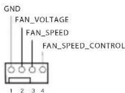
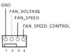
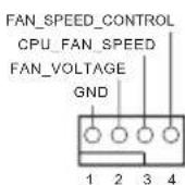
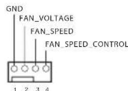
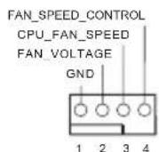
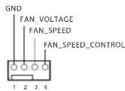
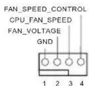
CPU Fan Connector (4-pin CPU_FAN1) (see p.1, No. 2)
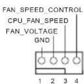
This motherboard provides a 4-Pin CPU fan (Quiet Fan) connector. If you plan to connect a 3-Pin CPU fan, please connect it to Pin 1-3.
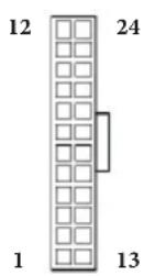
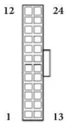
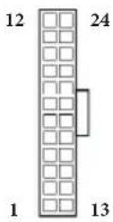
ATX Power Connector (24-pin ATXPWR1) (see p.1, No.5)
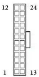
This motherboard provides a 24-pin ATX power connector. To use a 20-pin ATX power supply, please plug it along Pin 1 and Pin 13.
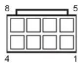
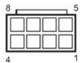
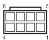
ATX 12V Power Connector (8-pin ATX12V1) (see p.1, No. 1)
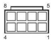
This motherboard provides an 8-pin ATX 12V power connector. To use a 4-pin ATX power supply, please plug it along Pin 1 and Pin 5.
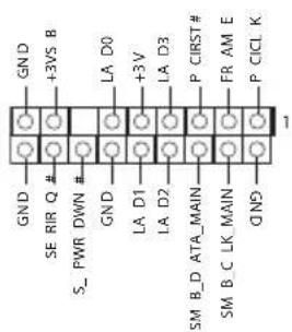
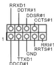
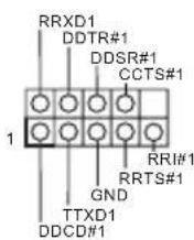
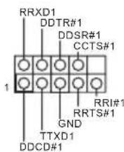
Serial Port Header (9-pin COM1) (see p.1, No. 19)
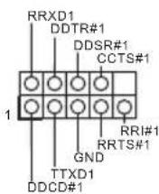
This COM1 header supports a serial port module.
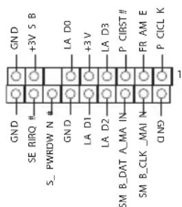
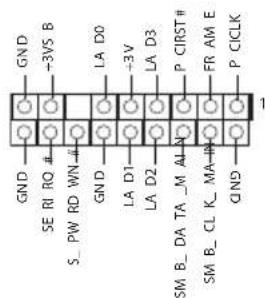
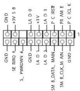
TPM Header (17-pin TPMS1) (see p.1, No.21)
This connector supports Trusted Platform Module (TPM) system, which can securely store keys, digital certificates, passwords, and data. A TPM system also helps enhance network security, protects digital identities, and ensures platform integrity.
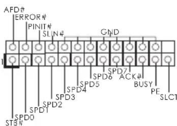
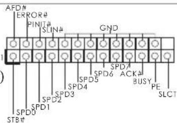
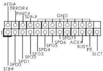
Print Port Header (25-pin LPT1) (see p.1, No. 20)
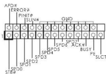
This is an interface for print port cable that allows convenient connection of printer devices.
2.7 M.2_SSD (NGFF) Module Installation Guide
The M.2, also known as the Next Generation Form Factor (NGFF), is a small size and versatile card edge connector that aims to replace mPCIe and mSATA. The M.2 Socket (M2_1) supports SATA3 6.0 Gb/s module and M.2 PCI Express module up to Gen2 x2 (10 Gb/s).
- If M2_1 is occupied by a SATA-type M.2 device, SATA3_3 will be disabled.
Installing the M.2_SSD (NGFF) Module
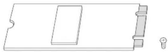
Step 1
Prepare a M.2_SSD (NGFF) module and the screw.
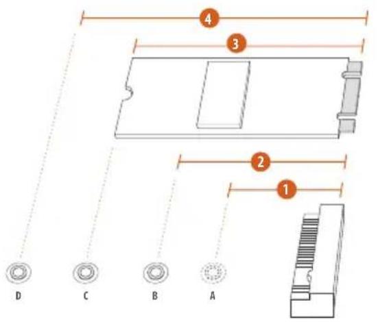
Step 2
Depending on the PCB type and length of your M.2_SSD (NGFF) module, find the corresponding nut location to be used.
No.1234
Nut Location A B C D
M.2_SSD (NGFF) Module Support List
| Vendor Interface P/N |
| ADATA SATA3 AXNS381E-128GM-B |
| ADATA SATA3 AXNS381E-256GM-B |
| ADATA SATA3 ASU800NS38-256GT-C |
| ADATA SATA3 ASU800NS38-512GT-C |
| ADATA PCIe3 x4 ASX7000NP-128GT-C |
| ADATA PCIe3 x4 ASX8000NP-256GM-C |
| ADATA PCIe3 x4 ASX7000NP-256GT-C |
| ADATA PCIe3 x4 ASX8000NP-512GM-C |
| ADATA PCIe3 x4 ASX7000NP-512GT-C |
| Apacer PCIe3 x4 AP240GZ280 |
| Corsair PCIe3 x4 CSSD-F240GBMP500 |
| Crucial SATA3 CT120M500SSD4 |
| Crucial SATA3 CT240M500SSD4 |
| Intel SATA3 Intel SSDSCCKGW080A401/80G |
| Intel PCIe3 x4 SSDPEKKF256G7 |
| Intel PCIe3 x4 SSDPEKKF512G7 |
| Kingston SATA3 SM2280S3 |
| Kingston PCIe3 x4 SKC1000/480G |
| Kingston PCIe2 x4 SH2280S3/480G |
| OCZ PCIe3 x4 RVD400 -M2280-512G (NVME) |
| PATRIOT PCIe3 x4 PH240GPM280SSDR NVME |
| Plextor PCIe3 x4 PX-128M8PeG |
| Plextor PCIe3 x4 PX-1TM8PeG |
| Plextor PCIe3 x4 PX-256M8PeG |
| Plextor PCIe3 x4 PX-512M8PeG |
| Plextor PCIe | PX-G256M6e |
| Plextor PCIe | PX-G512M6e |
| Samsung | PCIe3 x4 | SM961 MZVPW128HEGM (NVM) |
| Samsung | PCIe3 x4 | PM961 MZVLW128HEGR (NVME) |
| Samsung | PCIe3 x4 | 960 EVO (MZ-V6E250) (NVME) |
| Samsung | PCIe3 x4 | 960 EVO (MZ-V6E250BW) (NVME) |
| Samsung | PCIe3 x4 SM951 (NVME) |
| Samsung | PCIe3 x4 | SM951 (MZHPV256HDGL) |
| Samsung | PCIe3 x4 | SM951 (MZHPV512HDGL) |
| Samsung | PCIe3 x4 SM951 (NVME) |
| Samsung | PCIe x4 | XP941-512G (MZHPU512HCGL) |
| SanDisk | PCIe | SD6PP4M-128G |
| SanDisk | PCIe | SD6PP4M-256G |
| Team | SATA3 TM4PS4128GMC105 |
| Team | SATA3 TM4PS4256GMC105 |
| Team | SATA3 TM8PS4128GMC105 |
| Team | SATA3 TM8PS4256GMC105 |
| TEAM | PCIe3 x4 TM8FP2240G0C101 |
TEAMPCIe3 x4 TM8FP2480GC110
Transcend SATA3 TS256GMTS400
Transcend SATA3 TS512GMTS600
Transcend SATA3 TS512GMTS800
V-Color SATA3 VLM100-120G-2280B-RD
V-Color SATA3 VLM100-240G-2280RGB
V-Color SATA3 VSM100-240G-2280
V-Color SATA3 VLM100-240G-2280B-RD
WD SATA3 WDS100T1B0B-00AS40
WD SATA3 WDS240G1G0B-00RC30
WDPCIe3x4WDS256G1X0C-00ENX0(NVME)
WDPCIe3x4 WDS512G1X0C-00ENX0 (NVME)
For the latest updates of M.2_SSD (NFGG) module support list, please visit our website for details: http://www.asrock.com
1 Einleitung
ASRock B360M-HDV-Support-CD
1 x E/A-Blendenabschirmung
2x Serial-ATA-(SATA) Datenkabel (optional)
1 x Schraube fur M.2-Sockel (optional)
(4-polig, CHA_FAN1/WP)
(siehe S.1, Nr.4)
(4-polig, CHA_FAN2/WP)
(siehe S.1,Nr.14)
CPU-Lüfteranschluss
(4-polig, CPU_FAN1)
(siehe S.1,Nr.2)
Compatible ACPI 6.0 Wake Up Events
Compatible SMBIOS 2.7
Réglage de la tension CPU, GT_CPU, DRAM, PCH 1,05V
Supporto WOL (Wake-On-LAN)
Supporto Energy Efficient Ethernet 802.3az
Supporto PXE
I/O pannello
1 x porta mouse/tastiera PS/2
posteriore
1 x porta D-Sub
1xporta DVI-D
1 x porta HDMI
Express fino a Gen3 x4 (32 Gb/s)**
4 x Puertoos USB 3.1 Gen2 Type-A (10 Gb/s)
Iinck c IIO nIg ASRock B360M-HDV
1x3KpaHnHaHeiCnOpTaMnBBOJa-BbIBOJa
2xKa6eIy IpeJaun daHHbIX Serial ATA (SATA) (Iprno6peTaIOTcO tJeBHO)
1xBnHTIINrHHe3aM.2(PiNo6peTaIOTc8OTeJIbHO)
1.2 Texnueckne xapaKtepncTKN
BeHTnIaTOp NIN IOMIIa BOJHOrO OXJaKJeHnKoPIIyCa
Taxometp:BeHTnIaTOp IIT;KOpIyChoB BeHTnIaTOp NIII NOMIIa BOJHOrO OXJIaXKeHnI KOpIYCa
Becuymha pa6oTa (caBTOMaTHuecko peTyInpOBko CKOpocTN BpaueHn B 3aBncmOCTn OT TempeTpybI III): BeHTNIArTop IIT; KOpIysHO BeHTNIArTop NIN IOMNa BOJHO OXJaKeHn KOpNyCa PeryIpOBKa ckopocTN BpaueHn: BeHTNIArTop IIT; KOpIysHO BeHTNIArTop NIN IOMNa BOJHO OXJaKeHn KOpNyCa DaTynK BcKpbTna KOpNyCa KoHTpoJIb HaPraJkeHn: +12 B, +5 B, +3,3 B, HapPrJKeHne JaPa IIT, DRAM, PCH 1,05B
OnepaunohhbcnCTembl
Microsoft Windows 10 (64-pa3pЯня)
CeptnuФикauи
FCC,CE CoBmecTnMoCTb c ErP/EuP (Heo6xOIMM 6IOK IITaHnA, COOTBeTCTByIOUs CTaHApTy ErP/EuP)
^*C dononhumelbno u nfoopmauee o6 u3oelenu moKno 03nakomumbcna h e6-catme: http://www.asrock.com

Cledyem yumtbamb, umo pa2zOn npouecoppa, kknoua u3MeHene hacmpoek BIOS, npumeHenue mexnooou Untied Overclocking u ucnnoB3obAHue uHcmpymen6 pa320Ha ne3abucumbx npou3bodumenei, conpken c onpeodennmu puckom. Pa2zOn npoueccop moKem chuzumcb smabubocmb cucmembu uau daKe npubecmu K nobpekeho 0e komnoehmOB u ycmpoicme. Pa2zOn npouecoppa ocyuecmbneemc noB3obamen ha co6cbennbu pukk u 3a co6cbennbu chem. MHe He Hecem ombemcbeHHocmb 3a 8O3MOHNy uyep6, b3baHnbI pa2zOnom npouecoppa.
1.3 YcTaHOBka nepembIueK
YcTaHOBka IIepeMbIueK IOKa3Ha Ha npCuyKe. IIpn ycTaHOBke IIepeMbIuKN-KOJIInaKaHa KOHTaKTbI IIepeMbIuKa «3aMKHyTa>. EcII INepeMbIuKa-KOJIInaQK Ha KOHTaKTbI He YcTaHOBJIeHa, IIepeMbIuKa «pa3OMKHyTa>.
Short
Open
Ipeembyka c6poca
Hactpoek CMOS
(CLRCMOS1)
(cm. cTp. 1, No 11)

2-KOHTaKTHaIepeMbIyKa
3amKhyra: C6poc Hactpoek
CMOS
Pa3OMKHyTa: IIO yMOJIuaHnIO
CLRCMOS1 nCIOB3yETcIy ydaJIeHnI daHHbIX CMOS. B IaMaTn CMOS coepKataTc TaKHe IaHHbIe O HAcTPOKe CnCTEmbl, KaK CNCTEmHbI IapOJIb, IaTa, BpeM I IapAMeTpbl HaCTPOKn CnCTEmbl. YTo6bl c6pocNTb N 06HyI INapAePbI CNCTEmbl Ha HAcTPOKn IIO yMOJIaHnIO, BbIKIOUHTe KOMIIbIOTe IN3BJIeKITe BNIKY I3 PO3ETKN, a 3aTeM KOJIaUKOBoI IepEMbUKOJ 3aMKHI KOHTAKTBHa CLRCMOS1 Ha 3 ceKyIbI. IocNe c6poca HAcTpoek CMOS He 3a6yIbTe ChrTB KOJIaUKOByIO IepEMbUky. Ipr Heo6xOIMOCtN c6pocNTb HAcTPOKn CMOS cpa3y IocNe o6HOBJIeHnI BIOS cHaJaI Ipe3aIpy3HITe CnCTeMy, a 3aTeM BbIKIOuHTe KOMIIbIOTep IpeI c6pocOM HAcTPOeK CMOS

C6poc hacmpoek CMOS moem npubecmu K onpeidenenu 0ckpbumu kopnyca. Hmoob 0bnyumb 3anucb npdbdyuezo onpeidenenu 0ckpbumu kopnyca, ucnob3yume napamemp Clear Status (Obnyumb cocmonnue) BIOS.
1.4 Kolodkn npa3bembl, paCNOJIOXeHHbIe Ha cnCTeMHoI nIate

Pacnoonkennbte na cuminho name konodku u pa3bemy HE 6nioncm nepmbukam. HE ycmanabunbaume na 3mu konodku u pa3bemy nepmbukkoannauku. Ycmanobka nepmbueck-koanaukoB na 3mu konodku u pa3bemy mokeb b3bamb neycmpanumoe nobpekenue cuminho nnambu.
KoIOnKa cnCTeMHoH
IIaHHeIi
(9-KoHTaKTHa, PANEL1)
(cm.cTp.1,Ne 15)
IIOKJIIOUHTe paCIOJIOKeHHbIE Ha KOPIIyce KHOIIKY IINTaHnY, KHOIIKy Ipe3aRpy3KN I HINKATOp COCTOAHNc CNTeMBI K 3TOI KOIOJKe B COOTBeTCTBnC H3Na3HaueHNMe KOHTaKTOB, IIpNBedeHHbIM HJKe.Ipei IIOKJIIOUHeHm Ka6JIeONPpeJIeTIe IOIOJOHTeJIbHbI OTPNUaTeJIbHbIKoHTaKTbI.

PWRBTN (Khonka numahua):
Iodknoehue Khonku numahu, pacnolokhenhou na nepeohne naneu kopyca. Moknho hacmpoumbnocobbkiouehuucumemnpu hakamuu Khonku numahu.
RESET (Khonka c6poca):
Iodkouehue Khonku c6poca, pacnoiokehenho ha nepeohen naheu kopnyca. HaKmume Khonky c6poca, umobu nepe3anycmumb kOmnbomep, ecnu OH 3abuc u Hopmaanbni nepe3anyck Heo3moKeH.
PLED (cbemoduodhui uhdukamop numanu cucmebl):
Iodknoehue unukamop ccmohn, pacnookhenho na nepedne naneu kopyca. Cbemoduohn udukamop zopum, kozda cucmema pabomaem. Koeda cucmema haxodumc 6 pekume okuhan S1/S3, cbemoduod muaem. Koeda cucmema haxodumc 6 pekume okuhan S4 unu bkvloheha (S5), cbemoduod ne zopum.
HDLED (cbemoduodbu undukamop paobomb kecemko zo ducka):
Iopknouehue cbemoduohozo uhdukamopa paobmbkmo duka, pacnoonenho na nepeohne naneu. Cbemoduoohbu uhdukamop zopum, kozda kecmku'duck bbinonnem cumbhanue uunucb daHHbx.
Ipepehna naneb mokeim 6bmb pa3noi na pa3nbix kopnycax. Ha nepeonei naneu pacnoiokehi Khonka numanu, Khonka nepezanycka, uhdukamop numanu, uhdukamop paobmb jecmko ducka, duhamuk u m.d. Ipu nodknuehuu nepedhei naneu K omoi koloode npooba ka coombemcmyouum konmakmam.
Kolodka c pa3bemamn
IaTUnKa BcKpbITnA
KOpIyCa N IINHaMnKa
(7-KoHTaKTThb,SPK_C11)
(cM. cTp.1,No 16)
IpeHa3HaueHa
IIaIOKluOeHn
CBETOIOHO
HHNKaTopa NITaHn H
INHaMnKa KOpNyca.
Pa3beMBI Serial ATA3
(SATA3_0:
cm. cTp. 1, N2 12)
(SATA3_1:
cm. ctp. 1, No 13)
(SATA3_2:
CM. cTp. 1, No 9)
(SATA3_3:
cm. cTp. 1, N° 10)
(SATA3_4:
cm. cTp. 1, No 8)
(SATA3_5:
cm. cTp. 1, N27)
3TNIIECTbpa3bEmOB
SATA3PpeHa3HaueHb
IIINIOKJIIOUeHnKa6eJe
SATA BHyTpEHHIX
3aIOMNHaIOUnx yCTpOiCTB
IIINPEpeAun DaHHbIX CO
CKOPoCTbIO 6,0Γ6/c.
*Ecnn cIOT M2_1 3aHrt yctpoNCTBOM M.2 Tnna SATA, nHTeppeC SATA3_36yET OTKIOUeH.
KoIOnkN USB 2.0
(9-KoHTaKaTHa,USB_7_8)
(cm. ctp. 1, N° 17)
(9-KoHTaKTHa,
USB_13_14)
(cm.crp.1,N018)
Ha cncTeMHOI IaTe MMEOTcIbe KOIOJKN
USB 2.0. KaKJaa KIOJka
USB 2.0 IOIepeKnBaet IBaIIOPTa.
KoJouKu USB 3.1 Gen1
(19-KoHTaKTHa,
USB_11_12)
(cM.cTp.1,N6)
Ha MaTePnHcKo IIaTe IMeETcOJHa KOJOnKa.
Ta KoloKa USB 3.1 Gen1 IopTeJxNtBaeT IBa IopTa.
Ayuokoioka IepedneiHaHei
(9 KOHTaKTOB, HD_ AUDIOO1)
(cm.cTp.1,Ne22)
Ta KOIOKa IIpeHa3HaYeHa IINI IOKIIoueHnayIOuocTPOiCTB K IpeEHN ayIOHaHei.

-
Ayouocumema 660020 paspeuuehna noodepkuabaem fyHKuuo pacno3haaun pa3bema, no dne enpaabuou paobmheo6xodmo, mObo npobod nanenu Kopnyca noodepkuaba nepedauy cuHaane HDA. Incmpykuu no ycmanobke cucmemb cm. 8mom pykoobcmee u pykoobcmee ha kopnyc.
-
Ipu ucnonb3oanu ayduonanenu AC'97 noeknoyume ee k ayduokoloke nepehne naheu, ka yka3aHO danee:
A. Ihoeknoume Mic_IN (MIC) κ MIC2_L.
B. Itokkoume Audio_R (RIN) κ OUT2_R, Audio_L (LIN) κ OUT2_L.
C.Поdkанчumeme npobod 3a3emlenu(GND)к konmakey 3a3emlenu(GND).
D. Konmaikm MikRET u OUT_RET ucnonb3yomc monko do ayduonanenu bucok020 pa3peuienu. Ipu ucnonb3obananu ayduonanenu AC'97 ux nodknouamb ne hykno.
E. Ymobbi akmuupoabmb nepehui mukpofoh, nepeudume ha bknadky FrontMic nanenu ynpaeneu Realtek u ompezynupyame napamemp Recording Volume (Pomkocmb 3anucu).
Pa3bEmblIINBeHTNlAToPauNII NOMIIBOHOHO OXlaJxHnKOpNyca
(4-KOHTaKTHbI CHA FAN1/WP)
(cM.cTp.1,N4)
IaHHa MaTePnHcKa
IIaTa OCHaHeHa IByM
4-KoHTaKTHbIM pa3bEmOM
IIaCNCTeMbI BOJHO
OxJaKeHn KOpNyCa.
3-KoHTaKTHyIO CNCTeMy
BOJHO ROxJaXKeHn
KOpNyCa CJIeUyET IOJKnIOuAtb
K KOHTaKTam 1-3.
(4-KoHTaKTbI CHA FAN2/WP)
(cm.cTp.1,Ne 14)
Pa3bEm BeHTnIaTopa oxJaKdEHHIpoIeCCopa
(4 KOHTAKTA, CPU_FAN1)
(cM.cTp.1,N2)

Ta MaTePnHcKa IHaTa
Cha6KeHa 4-KoHTaKTHBIM
pa3bemOM II
MaIOUIyMIIeTO BeHTNIATopa
II.EcIN BbI co6HpaeTecb
IOIKIOHTb 3-KoHTaKTbIH
BeHTNIATOP OXIAJKeHH
IpoIeCCopa,IOIKIOUaJIte
ero K KOHTaKTam 1-3.
Pa3bem IIITaHnA TX (24 KOHTaKaTa,ATXPR1) (cm. cTp. 1, N5)
Ta MaTePnHcKa Pnata
OchaHeHa 24-KoHTaKTHbIM
pa3bEMOM IItAHNAx. Yo6bl
HCIOJIb3OBaTb 20-KoHTaKTHbI
pa3bEm IITaHNAx ATX,
IOIKIOUHTe ERO BIOJIb KOHTaKTA
1 N KOHTaKTA 13.
Pa3bem HHTaHnA TX 12B (8 KOHTaKTOB,ATX12V1) (cm. cTp.1,N1
Ta MaTePnHcKaI IaTa
OchaHeHa 8-KoHTaKTHbIM
pa3BeMOM NITaHNA ATX
12B. Yo6bI nCIOJIb3OBaTb
4-KoHTaKTHbI pa3BeM INITaHNA
ATX,IOJKNIOUHTe eRO BIOJIb
KOHTaKTA 1 N KOHTaKTA 5.
KoIOnKa
IOcJIeIOBaTeJIbHOrO IopTa
(9-KoHTaKTHaJ, COM1)
(cm. cTp. 1, No 19)
KoIOKa COM1 IOJIepKINBaET IOIKIIOUeHne MOyJII IOcIEIOBATEIbHOrO IOpTa.
KoIOnKa TPM (17 KOHTaKTOB, TPMS1) (cm. cTp. 1, No 21)
TOT pa3bem o6ecIeHBAeT
IIIOJIepKky cncTeMbTrusted
Platform Module (TPM), KOtOpa
cno6Ha o6ecIeHTb HaJeKHOe
XpaHeHne KIOUey, IIOΦpOBbIX
cepTNKATOB, napoJIeN
JaHHbIX.CnCTema TPM taKKe
IOBbIIaET yPOBEh CeTEBOI
6e3OIIaCHOCTN, 3aIIuIaET
IIΦpOBbIe INeHTNΦkAToPbI
IN O6ecIeHbAE TIEIOCTHOCTb
IIaTΦopMbI.
KoIOnKa IopTa IIpHHTepa (25-KoHTaKTHaJ, LPT1) (cm. cTp. 1, No 20)
TO- HHTepcEic nIa IIOKJIIOUeHnKa6eIa IOpTa IIpHTepa,ObecIeUNBaIOuIyIO6Hoe IOIKJIIOUeHne ycTPOCTB NeaTN.
1 Introdução
Placa-mae ASRock B360M-HDV (Micro ATX Form Factor)
1 tane G/C Paneli Kalkani
2 tane Seri ATA (SATA) Veri Kablosu (Istege Baigh)
M.2 Yuvasi icin 1 tane vida (Istege Bagh)
1.2 Özellikler
6 tane SATA3 6,0 Gb/sn Baglayici, NCQ, AHCI ve Tak Calistir destekler*
B. Audio_R (RIN) = OUT2_R = 出端到Audio_L (LIN) = OUT2_L = 两端
C. GND( GND)
D.MIC_RETOUT_RET=HDOIOO 97
E. 《“FrontMic”》
K
(4) CHA_FAN1/WP)
(1.3.1)
i 4
2.2.3.3 CPU
S#
(4 CHA_FAN2/WP)
(1.30)
i 4 CPU
KITRKTAIATREDAHJ 3 CPU 1-3
CPU 型封装电路
(4.1 CPU_FAN1)
(1.3.1)
ATX封装用封装
(24 号ATXPWR1)
(1.0i,5.
iATXJ 24
ATXJ .20
ATXJ1
13
ATX 12V 击発用電開關器
(8ATX12V1)
(1.0i,1.
iATX12VJ08ATX12VJ08ATX12VJ08ATX12VJ08ATX12VJ08ATX12VJ08ATX12VJ08ATX12VJ08ATX12VJ08ATX12VJ08ATX12VJ08ATX12VJ08ATX12VJ08ATX1
SRIIeE EET
(9 副 COM1)
(1.3019,19)
COM1 越達不是社利部托贝多台
TPM
(17)TPMS1)
(1.301,21.301)
iKkntTnK,diJIeJIn
H,amH&dEITeRan
Kt#eJbQaHsUohnTPM
(Trusted Platform Module)
S##t#oJtiJrHcNt .TPM sT#n #n 13eTwO K bAn oq
hco ,diJIeT#n 1nW ## H
mP#L#p#u#g#yUzH#n
Ta.
印
(25.1 LPT1)
(1期i,20年
元隆TJ 1
1はいもに

1.1 ロルケーダ的内容

1.2 仕樣
CPU
TM
μ
TM
TM, Intel® UHD
LAN
Type-A
(10 Gb/s)
** Intel OptaneTM
os

1.3 パンバ一設定
Short
Open
(CLRCMOS1)


1.4 才不ロームのハリローとネクタ


(SATA3_0:
(SATA3_1:
(SATA3_2:
(SATA3_3:
(SATA3_4:
(SATA3_5:

- 2.
1简介
If you need to contact ASRock or want to know more about ASRock, you're welcome to visit ASRock's website at http://www.asrock.com; or you may contact your dealer for further information. For technical questions, please submit a support request form at https://event.asrock.com/tsd.asp
ASRock Incorporation
2F., No.37, Sec. 2, Jhongyang S. Rd., Beitou District,
Taipei City 112, Taiwan (R.O.C.)
ASRock EUROPE B.V.
Bijsterhuizen 11-11
6546 AR Nijmegen
The Netherlands
Phone: +31-24-345-44-33
Fax: +31-24-345-44-38
ASRock America, Inc.
13848 Magnolia Ave, Chino, CA91710
U.S.A.
Phone: +1-909-590-8308
Fax: +1-909-590-1026
Per FCC Part 2 Section 2.1077(a)

Responsible Party Name: ASRock Incorporation
Address: 13848 Magnolia Ave, Chino, CA91710
Phone/Fax N o: +1-909-590-8308/+1-909-590-1026
hereby declares that the product
Product Name : Motherboard
Model Number: B360M-HDV
Conforms to the following specifications:
FCCPart15,SubpartB,Unintentional Radiators
This device complies with part 15 of the FCC Rules. Operation is subject to the following two conditions: (1) This device may not cause harmful interference, and (2) this device must accept any interference received, including interference that may cause undesired operation.
Representative Person's Name: James
Signature:

Date: May 12, 2017
ASRock
For the following equipment:
Motherboard
(Product Name)
B360M-HDV/ASRock
(Model Designation / Trade Name)
ASRock Incorporation
(Manufacturer Name)
2F., No.37, Sec. 2, Jhongyang S. Rd., Beitou District, Taipei City 112, Taiwan (R.O.C.)
(Manufacturer Address)
EMC—Directive 2014/30/EU (from April 20th, 2016)
EN 55022:2010/AC:2011 Class B
EN 55024:2010/A1:2015
EN 61000-3-3:2013
□LVD—Directive 2014/35/EU (from April 20th, 2016)
EN60950-1:2011+A2:2013
EN 60950-1:2006/A12:2011
Directive 2011/65/EU
(EU conformity marking)
C E
ASRock EUROPE B.V.
(Company Name)
Bijsterhuizen 1111 6546 AR Nijmegen The Netherlands
(Company Address)
Person responsible for making this declaration:

(Name, Surname)
A.V.P
(Position / Title)
March 9, 2018
(Date)
P/N: 15G062081000AK V1.0