
Z97 Pro4 - Motherboard ASROCK - Free user manual and instructions
Find the device manual for free Z97 Pro4 ASROCK in PDF.
User questions about Z97 Pro4 ASROCK
0 question about this device. Answer the ones you know or ask your own.
Ask a new question about this device
Download the instructions for your Motherboard in PDF format for free! Find your manual Z97 Pro4 - ASROCK and take your electronic device back in hand. On this page are published all the documents necessary for the use of your device. Z97 Pro4 by ASROCK.
USER MANUAL Z97 Pro4 ASROCK
Published April 2014
Copyright©2014 ASRock INC. All rights reserved.
Copyright Notice:
No part of this documentation may be reproduced, transcribed, transmitted, or translated in any language, in any form or by any means, except duplication of documentation by the purchaser for backup purpose, without written consent of ASRock Inc.
Products and corporate names appearing in this documentation may or may not be registered trademarks or copyrights of their respective companies, and are used only for identification or explanation and to the owners' benefit, without intent to infringe.
Disclaimer:
Specifications and information contained in this documentation are furnished for informational use only and subject to change without notice, and should not be constructed as a commitment by ASRock. ASRock assumes no responsibility for any errors or omissions that may appear in this documentation.
With respect to the contents of this documentation, ASRock does not provide warranty of any kind, either expressed or implied, including but not limited to the implied warranties or conditions of merchantability or fitness for a particular purpose.
In no event shall ASRock, its directors, officers, employees, or agents be liable for any indirect, special, incidental, or consequential damages (including damages for loss of profits, loss of business, loss of data, interruption of business and the like), even if ASRock has been advised of the possibility of such damages arising from any defect or error in the documentation or product.

This device complies with Part 15 of the FCC Rules. Operation is subject to the following two conditions:
(1) this device may not cause harmful interference, and
(2) this device must accept any interference received, including interference that may cause undesired operation.
CALIFORNIA, USA ONLY
The Lithium battery adopted on this motherboard contains Perchlorate, a toxic substance controlled in Perchlorate Best Management Practices (BMP) regulations passed by the California Legislature. When you discard the Lithium battery in California, USA, please follow the related regulations in advance.
"Perchlorate Material-special handling may apply, see www.dtsc.ca.gov/hazardouswaste/perchlorate"
ASRock Website: http://www.asrock.com

The terms HDMI ^™ and HDMI High-Definition Multimedia Interface, and the HDMI logo are trademarks or registered trademarks of HDMI Licensing LLC in the United States and other countries.

Motherboard Layout
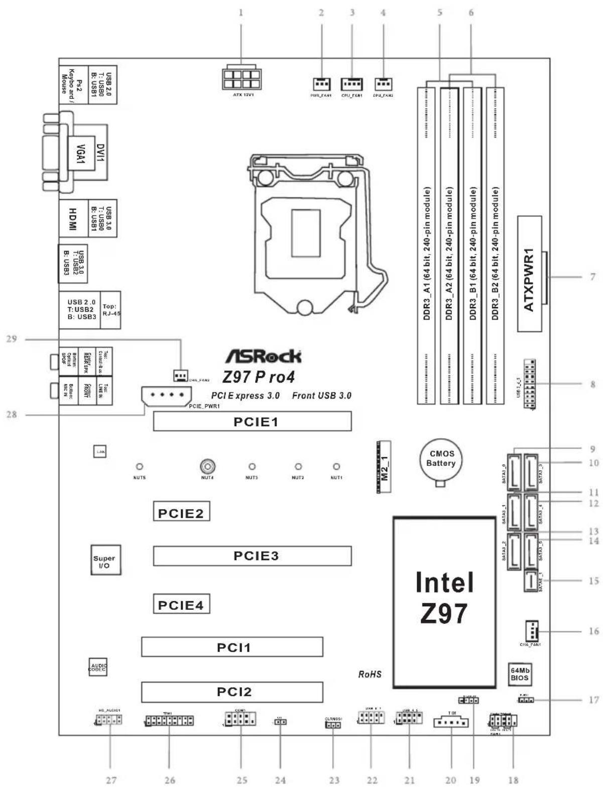
No. Description
1 ATX 12V Power Connector (ATX12V1)
2 Power Fan Connector (PWR_FAN1)
3 CPU Fan Connector (CPU_FAN1)
4 CPU Fan Connector (CPU_FAN2)
5 2 x 240-pin DDR3 DIMM Slots (DDR3_A1, DDR3_B1)
6 2 x 240-pin DDR3 DIMM Slots (DDR3_A2, DDR3_B2)
7 ATX Power Connector (ATXPWR1)
8 USB 3.0 Header (USB3_4_5)
9 SATA3 Connector (SATA3_0)
10 SATA3 Connector (SATA3_3)
11 SATA3 Connector (SATA3_1)
12 SATA3 Connector (SATA3_4)
13 SATA3 Connector (SATA3_2)
14 SATA3 Connector (SATA3_5)
15 SATA Express Connector (SATAE_1)
16 Chassis Fan Connector (CHA_FAN1)
17 Power LED Header (PLED1)
18 System Panel Header (PANEL1)
19 Chassis Speaker Header (SPEAKER1)
20 Thunderbolt AIC Connector (TB1)
21 USB 2.0 Header (USB_4_5)
22 USB 2.0 Header (USB_6_7)
23 Clear CMOS Jumper (CLRCMOS1)
24 Chassis Intrusion Header (CI1)
25 COM Port Header (COM1)
26 TPM Header (TPM1)
27 Front Panel Audio Header (HD_AUDIO1)
28 PCIe Power Connector (PCIE_PWR1)
29 Chassis Fan Connector (CHA_FAN2)
I/O Panel
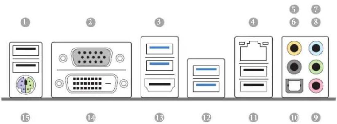
No. Description No. Description
1 USB 2.0 Ports (USB01) 9 Microphone (Pink)
2 D-Sub Port 10 Optical SPDIF Out Port
3 USB 3.0 Ports (USB3_0_1) 11 USB 2.0 Ports (USB23)
4 LAN RJ-45 Port* 12 USB 3.0 Ports (USB3_2_3)
5 Central / Bass (Orange) 13 HDMI Port
6 Rear Speaker (Black) 14 DVI-D Port
7 Line In (Light Blue) 15 PS/2 Mouse/Keyboard Port
8 Front Speaker (Lime) ^**
* There are two LEDs on each LAN port. Please refer to the table below for the LAN port LED indications.
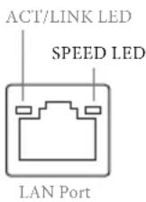
| Activity / Link LED Speed LED | |||
| Status Description Status Description | |||
| Off No Link Off | 10Mbps connection | ||
| Blinking | Data Activity | Orange | 100Mbps connection |
| On Link Green | 1Gbps connection | ||
** If you use a 2-channel speaker, please connect the speaker's plug into "Front Speaker Jack". See the table below for connection details in accordance with the type of speaker you use.
| Audio Output Channels | Front Speaker (No. 8) | Rear Speaker (No. 6) | Central / Bass (No. 5) | Line In (No. 7) |
| 2 V -- -- -- | ||||
| 4 V V -- -- | ||||
| 6 V V V -- | ||||
| 8 V V V V |

To enable Multi-Streaming, you need to connect a front panel audio cable to the front panel audio header. After restarting your computer, you will find the "Mixer" tool on your system. Please select "Mixer ToolBox", click "Enable playback multi-streaming", and click "ok". Choose "2CH", "4CH", "6CH", or "8CH" and then you are allowed to select "Realtek HDA Primary output" to use the Rear Speaker, Central/Bass, and Front Speaker, or select "Realtek HDA Audio 2nd output" to use the front panel audio.
Chapter 1 Introduction
Thank you for purchasing ASRock Z97 Pro4 motherboard, a reliable motherboard produced under ASRock's consistently stringent quality control. It delivers excellent performance with robust design conforming to ASRock's commitment to quality and endurance.

Because the motherboard specifications and the BIOS software might be updated, the content of this manual will be subject to change without notice. In case any modifications of this manual occur, the updated version will be available on ASRock's website without further notice. If you require technical support related to this motherboard, please visit our website for specific information about the model you are using. You may find the latest VGA cards and CPU support list on ASRock's website as well. ASRock website http://www.asrock.com.
1.1 Package Contents
ASRock Z97 Pro4 Motherboard (ATX Form Factor)
ASRock Z97 Pro4 Quick Installation Guide
ASRock Z97 Pro4 Support CD
2 x Serial ATA (SATA) Data Cables (Optional)
1 x I/O Panel Shield
1 x Screw for M.2_SSD (NGFF) Socket 3
1.2 Specifications
| Platform | ATX Form FactorHigh Density Glass Fabric PCB |
| Unique Feature | ASRock Super AlloyPremium Alloy Choke (Reduces 70% core loss compared to iron powder choke)NexFETTM MOSFET12K Platinum Caps (100% Japan made high quality conductive polymer capacitors)Sapphire Black PCBASRock Full Spike ProtectionASRock CloudASRock APP Shop |
| CPU | Supports 4thGen & 5thGeneration Intel® CorethProcessors (Socket 1150)Digi Power design6 Power Phase designSupports Intel® Turbo Boost 2.0 TechnologySupports Intel® K-Series unlocked CPUsSupports ASRock BCLK Full-range Overclocking |
| Chipset | Intel® Z97 |
| Memory | Dual Channel DDR3 Memory Technology4 x DDR3 DIMM SlotsSupports DDR3 2933+(OC)/2800(OC)/2400(OC)/2133(OC)/1866(OC)/1600/1333/1066 non-ECC, un-buffered memoryMax. capacity of system memory: 32GB (see CAUTION)Supports Intel® Extreme Memory Profile (XMP) 1.3 / 1.2 |
| Expansion Slot | 1 x PCI Express 3.0 x16 Slot (PCIE1: x16 mode)1 x PCI Express 2.0 x16 Slot (PCIE3: x4 mode)* If PCIE2 or PCIE4 slot is occupied, PCIE3 slot will run at x2 mode.2 x PCI Express 2.0 x1 Slots2 x PCI SlotsSupports AMD Quad CrossFireXTM and CrossFireXTM |
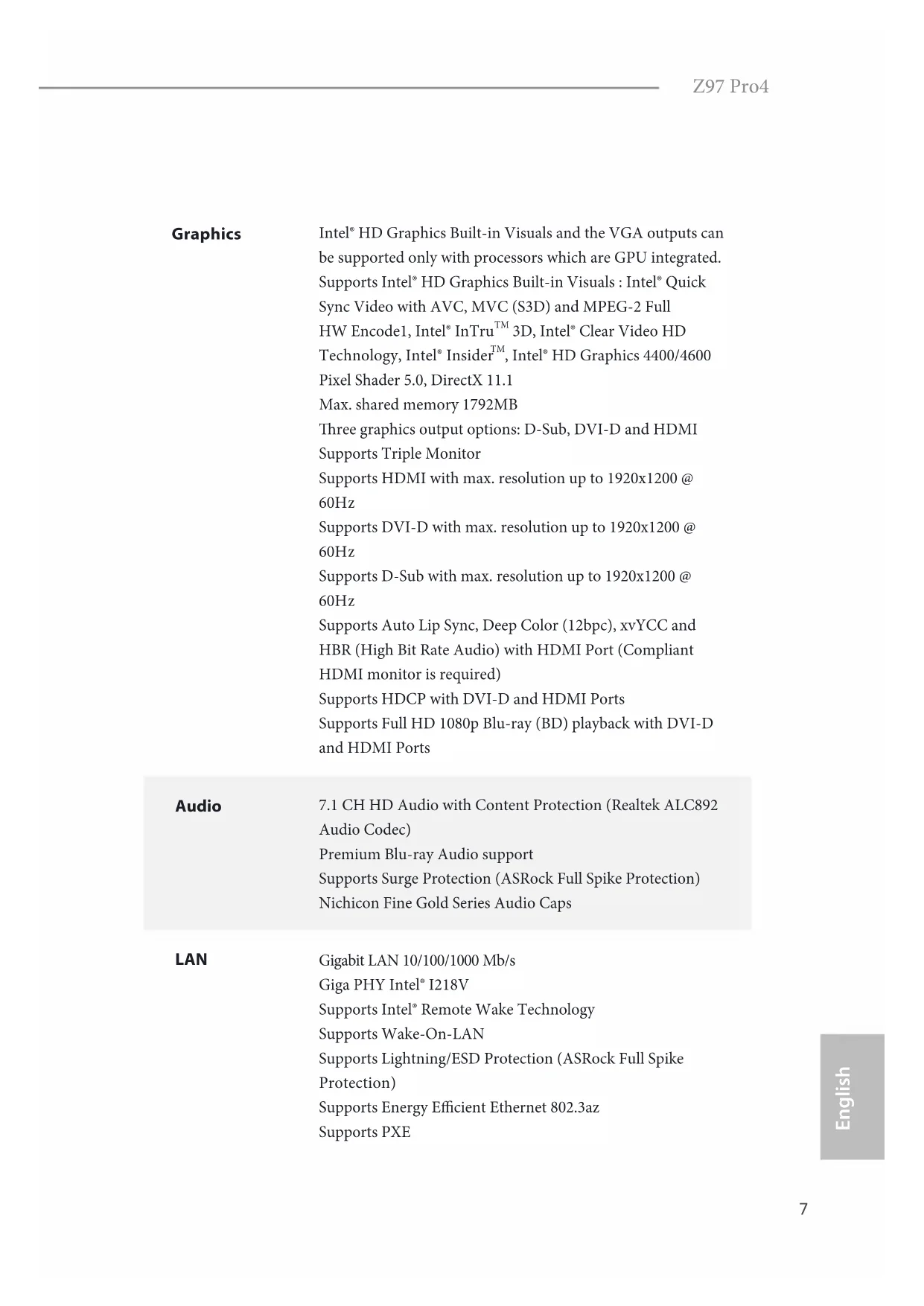
Graphics
Intel® HD Graphics Built-in Visuals and the VGA outputs can be supported only with processors which are GPU integrated. Supports Intel® HD Graphics Built-in Visuals: Intel® Quick Sync Video with AVC, MVC (S3D) and MPEG-2 Full HW Encode1, Intel® InTru™ 3D, Intel® Clear Video HD Technology, Intel® Insider™, Intel® HD Graphics 4400/4600 Pixel Shader 5.0, DirectX 11.1 Max. shared memory 1792MB Three graphics output options: D-Sub, DVI-D and HDMI Supports Triple Monitor Supports HDMI with max. resolution up to 1920x1200 @ 60Hz Supports DVI-D with max. resolution up to 1920x1200 @ 60Hz Supports D-Sub with max. resolution up to 1920x1200 @ 60Hz Supports Auto Lip Sync, Deep Color (12bpc), xvYCC and HBR (High Bit Rate Audio) with HDMI Port (Compliant HDMI monitor is required) Supports HDCP with DVI-D and HDMI Ports Supports Full HD 1080p Blu-ray (BD) playback with DVI-D and HDMI Ports
Audio
7.1 CH HD Audio with Content Protection (Realtek ALC892 Audio Codec) Premium Blu-ray Audio support Supports Surge Protection (ASRock Full Spike Protection) Nichicon Fine Gold Series Audio Caps
LAN
Gigabit LAN 10/100/1000 Mb/s Giga PHY Intel® I218V Supports Intel® Remote Wake Technology Supports Wake-On-LAN Supports Lightning/ESD Protection (ASRock Full Spike Protection) Supports Energy Efficient Ethernet 802.3az Supports PXE
Rear Panel I/O
1 x PS/2 Mouse/Keyboard Port
1 x D-Sub Port
1 x DVI-D Port
1 x HDMI Port
1 x Optical SPDIF Out Port
4 x USB 2.0 Ports (Supports ESD Protection (ASRock Full Spike Protection))
4 x USB 3.0 Ports (Supports ESD Protection (ASRock Full Spike Protection))
1 x RJ-45 LAN Port with LED (ACT/LINK LED and SPEED LED)
HD Audio Jacks: Rear Speaker / Central / Bass / Line in / Front Speaker / Microphone
Storage
6 x SATA3 6.0 Gb/s Connectors, support RAID (RAID 0, RAID 1, RAID 5, RAID 10, Intel Rapid Storage Technology
13 and Intel Smart Response Technology), NCQ, AHCI and Hot Plug
1 x SATA Express Connector (shared with SATA3_4, SATA3_5 and M.2_SSD (NGFF) Socket 3)
* Support to be announced
1 x M.2_SSD (NGFF) Socket 3, supports M.2 SATA3 6.0 Gb/s module and M.2 PCI Express module up to Gen2 x2 (10 Gb/s)
Connector
1 x COM Port Header
1 x Chassis Intrusion Header
1 x TPM Header
1 x Power LED Header
2 x CPU Fan Connectors (1 x 4-pin, 1 x 3-pin)
2 x Chassis Fan Connectors (1 x 4-pin, 1 x 3-pin)
1 x Power Fan Connector (3-pin)
1 x 24 pin ATX Power Connector
1 x 8 pin 12V Power Connector
1 x PCIe Power Connector
1 x Front Panel Audio Connector
1 x Thunderbolt AIC Connector
2 x USB 2.0 Headers (Support 4 USB 2.0 ports) (Supports ESD Protection (ASRock Full Spike Protection))
1 x USB 3.0 Header (Supports 2 USB 3.0 ports) (Supports ESD Protection (ASRock Full Spike Protection))
| BIOSFeature | 64Mb AMI UEFI Legal BIOS with multilingual GUI supportACPI 1.1 Compliant wake up eventsSMBIOS 2.3.1 supportCPU, DRAM, PCH 1.05V, PCH 1.5V Voltage Multi-adjust-ment |
| SupportCD | Drivers, Utilities, AntiVirus Software (Trial Version), GoogleChrome Browser and Toolbar, Start8 (30 days trial), KloudianOrbweb.ME Professional (Win 8.1) |
| HardwareMonitor | CPU/Chassis temperature sensingCPU/Chassis/Power Fan TachometerCPU/Chassis Quiet Fan (Auto adjust chassis fan speed byCPU temperature)CPU/Chassis Fan multi-speed controlCASE OPEN detectionVoltage monitoring: +12V, +5V, +3.3V, CPU Vcore |
| OS | Microsoft® Windows® 8.1 32-bit / 8.1 64-bit / 8 32-bit / 8 64-bit / 7 32-bit / 7 64-bit |
| Certifications | FCC, CE, WHQLErP/EuP ready (ErP/EuP ready power supply is required) |
* For detailed product information, please visit our website: http://www.asrock.com

Please realize that there is a certain risk involved with overclocking, including adjusting the setting in the BIOS, applying Untied Overclocking Technology, or using third-party overclocking tools. Overclocking may affect your system's stability, or even cause damage to the components and devices of your system. It should be done at your own risk and expense. We are not responsible for possible damage caused by overclocking.

Due to limitation, the actual memory size may be less than 4GB for the reservation for system usage under Windows ^® 32-bit operating systems. Windows ^® 64-bit operating systems do not have such limitations. You can use ASRock XFast RAM to utilize the memory that Windows ^® cannot use.
1.3 Unique Features

ASRock Super Alloy
This motherboard is specially designed with Super Alloy Technology for faster, stabler, and more durable performance, including XXL Aluminum Alloy Heatsink, Premium Alloy Choke, Dual-Stack MOSFET, NexFET ^TM MOSFET, 12K Platinum Cap, and Sapphire Black PCB.

ASRock Full Spike Protection
A technology consists of 3 unique features: Surge Protection, Lightning Protection, and ESD Protection. By adding specialized ICs and reworking circuits, the onboard USB ports, LAN ports, and MOSFETs in critical areas are all well protected from surges, spikes, and electrostatic discharge.

ASRock Cloud
ASRock partners with Kloudian to make your mobile devices connect to your PC seamlessly! ASRock Cloud allows you to get connected with your PC's files, music, photos, and video clips remotely with tablets anytime, anywhere.
* OrbWeb ME is provided by a third party. Restriction may apply and the offer is subject to change, termination or discontinuation by the third party without prior notice. Please visit the website for further details: http://www.asrock.com/feature/cloud/index.html

ASRock APP Shop
ASRock APP Shop is designed for your convenience. We provide various apps and support software for users to download on the mainpage of APP Shop. You can easily optimize your system and keep your motherboard up to date with a few clicks.

ASRock A-Tuning
A-Tuning is ASRock's multi purpose software suite with a new interface, more new features and improved utilities.

ASRock Disk Health Report
Displaying detailed HDD information. You can check the model names, capacities, temperatures, SMART info, health status, and other information of your HDDs here.

ASRock USB Key
In a world where time is money, why waste precious time everyday typing usernames to log in to Windows? Why should we even bother memorizing those foot long passwords? Just plug in the USB Key and let your computer log in to windows automatically!

ASRock APP Charger
Simply by installing the ASRock APP Charger makes your iPhone/iPad/iPod Touch charge up to 40% faster than before on your computer. ASRock APP Charger allows you to quickly charge many Apple devices simultaneously and even supports continuous charging when your PC enters into Standby mode (S1), Suspend to RAM (S3), hibernation mode (S4) or power off (S5).

ASRock XFast LAN
ASRock XFast LAN provides faster internet access, which includes the benefits listed below. LAN Application Prioritization: You can configure your application's priority ideally and add new programs to the list. Lower Latency in Game: After setting online game's priority higher, it can lower the latency in games. Traffic Shaping: You can watch Youtube HD videos and download simultaneously. Real-Time Analysis of Your Data: With the status window, you can easily recognize which data streams you are currently transferring.

ASRock XFast RAM
ASRock XFast RAM is included in A-Tuning. It fully utilizes the memory space that cannot be used under Windows® 32-bit operating systems. ASRock XFast RAM shortens the loading time of previously visited websites, making web surfing faster than ever. And it also boosts the speed of Adobe Photoshop 5 times faster. Another advantage of ASRock XFast RAM is that it reduces the frequency of accessing your SSDs or HDDs in order to extend their lifespan.

ASRock Restart to UEFI
Windows® 8 brings the ultimate boot up experience. The lightning boot up speed makes it hard to access the UEFI setup. ASRock Restart to UEFI allows users to enter the UEFI automatically when turning on the PC. By enabling this function, the PC will enter the UEFI directly after you restart.

ASRock Full HD UEFI
All new Full HD UEFI with a resolution of 1920 x 1080. The UEFI should be designed easy to use and setup. With Full HD resolution, now it is much easier and clearer for all users to setup, optimize, and update their BIOS.

ASRock My Favorites in UEFI
Another handy design in ASRock UEFI. You can select and add commonly used BIOS options to "My Favorites" by clicking the asterisk icon at the upper right hand corner of the screen. These chosen options will show up on "My Favorites" page in UEFI.

ASRock UEFI Guide
Need help to optimize your UEFI setting? Got lost among UEFI pages? Just select "UEFI Guide"! The tutorial will explain every detailed setting and help you to customize your UEFI easily.

ASRock Instant Flash
ASRock Instant Flash is a BIOS flash utility embedded in Flash ROM. This convenient BIOS update tool allows you to update the system BIOS in a few clicks without preparing an additional floppy diskette or other complicated flash utility. Just save the new BIOS file to your USB storage and launch this tool by pressing

ASRock Internet Flash
ASRock Internet Flash downloads and updates the latest UEFI firmware version from our servers for you without entering Windows OS. Please setup network configuration before using Internet Flash.

ASRock Crashless BIOS
ASRock Crashless BIOS allows users to update their BIOS without fear of failing. If power loss occurs during the BIOS updating process, ASRock Crashless BIOS will automatically finish the BIOS update procedure after regaining power. Please note that BIOS files need to be placed in the root directory of your USB disk. Only USB 2.0 ports support this feature.

ASRock OMG (Online Management Guard)
Administrators are able to establish an internet curfew or restrict internet access at specified times via OMG. You may schedule the starting and ending hours of internet access granted to other users. In order to prevent users from bypassing OMG, guest accounts without permission to modify the system time are required.

ASRock UEFI System Browser
ASRock System Browser shows the overview of your current PC and the devices connected.

ASRock UEFI Tech Service
Contact ASRock Tech Service by sending a support request from the UEFI setup utility if you are having trouble with your PC.

ASRock Dehumidifier Function
Users may prevent motherboard damages due to dampness by enabling “Dehumidifier Function”. When enabling Dehumidifier Function, the computer will power on automatically to dehumidify the system after entering S4/S5 state.

ASRock Easy RAID Installer
ASRock Easy RAID Installer can help you to copy the RAID driver from the support CD to your USB storage device. After copying the RAID driver to your USB storage device, please change "SATA Mode" to "RAID", then you can start installing the OS in RAID mode.
ASRock Easy Driver Installer
For users that don't have an optical disk drive to install the drivers from our support CD, Easy Driver Installer is a handy tool in the UEFI that installs the LAN driver to your system via an USB storage device, then downloads and installs the other required drivers automatically.
Chapter 2 Installation
This is an ATX form factor motherboard. Before you install the motherboard, study the configuration of your chassis to ensure that the motherboard fits into it.
Pre-installation Precautions
Take note of the following precautions before you install motherboard components or change any motherboard settings.
Make sure to unplug the power cord before installing or removing the motherboard components. Failure to do so may cause physical injuries and damages to motherboard components.
In order to avoid damage from static electricity to the motherboard's components, NEVER place your motherboard directly on a carpet. Also remember to use a grounded wrist strap or touch a safety grounded object before you handle the components.
Hold components by the edges and do not touch the ICs.
Whenever you uninstall any components, place them on a grounded anti-static pad or in the bag that comes with the components.
When placing screws to secure the motherboard to the chassis, please do not over-tighten the screws! Doing so may damage the motherboard.
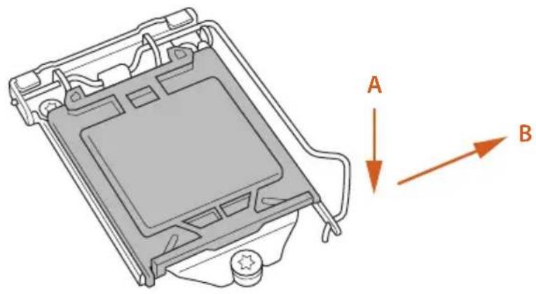
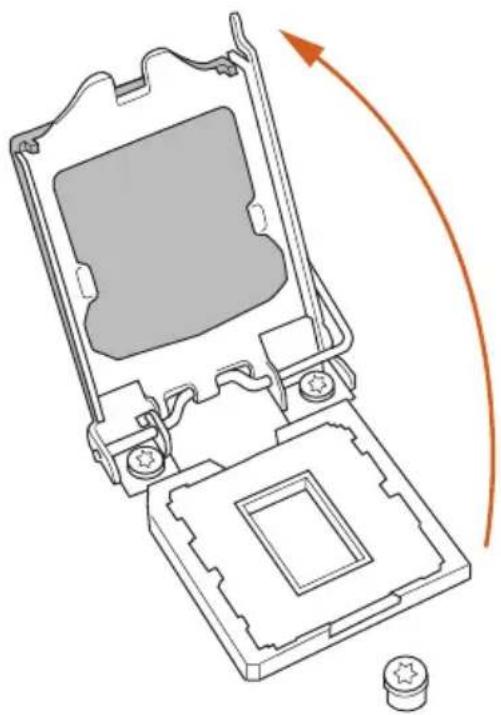
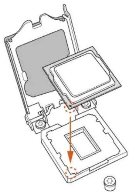
2.1 Installing the CPU

- Before you insert the 1150-Pin CPU into the socket, please check if the PnP cap is on the socket, if the CPU surface is unclean, or if there are any bent pins in the socket. Do not force to insert the CPU into the socket if above situation is found. Otherwise, the CPU will be seriously damaged.
- Unplug all power cables before installing the CPU.
1
natural_image
Technical line drawing of a mechanical component with labeled directional arrows (A and B), no readable text or symbols present.2
natural_image
Technical line drawing of a mechanical component with an arrow indicating rotation or assembly (no text or symbols present)3
natural_image
Technical diagram of a computer processor internal structure showing mounting holes and a highlighted section (no text or symbols)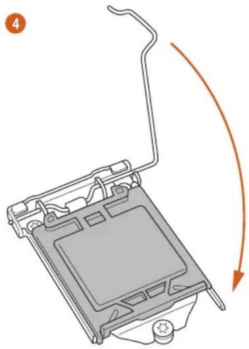
natural_image
Diagram of a computer monitor with an open lid and scroll, showing a curved orange arrow indicating rotation (no text or symbols present)5
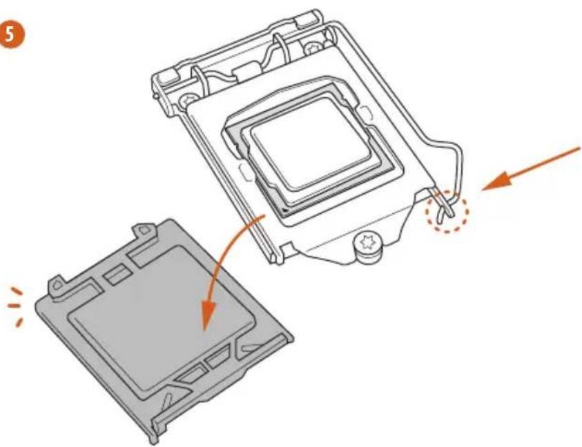
natural_image
Diagram showing a computer processor casing with an open lid and a highlighted internal component, no text or symbols present.
Please save and replace the cover if the processor is removed. The cover must be placed if you wish to return the motherboard for after service.
2.2 Installing the CPU Fan and Heatsink
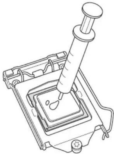
natural_image
Line drawing of a pipette dispensing liquid into a square container (no text or symbols)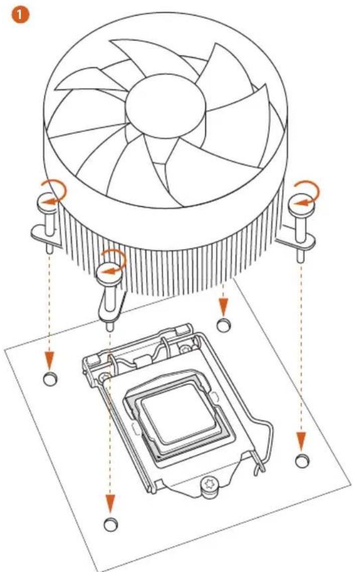
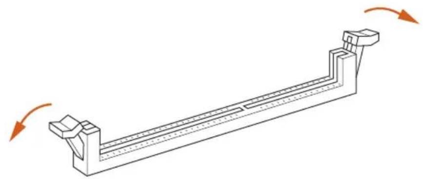
2.3 Installing Memory Modules (DIMM)
This motherboard provides four 240-pin DDR3 (Double Data Rate 3) DIMM slots, and supports Dual Channel Memory Technology.

- For dual channel configuration, you always need to install identical (the same brand, speed, size and chip-type) DDR3 DIMM pairs.
- It is unable to activate Dual Channel Memory Technology with only one or three memory module installed.
- It is not allowed to install a DDR or DDR2 memory module into a DDR3 slot; otherwise, this motherboard and DIMM may be damaged.
Dual Channel Memory Configuration
Priority DDR3_A1 DDR3_A2 DDR3_B1 DDR3_B2
| 1 Populated Populated | |||
| 2 Populated Populated | |||
| 3 Populated Populated Populated Populated |

The DIMM only fits in one correct orientation. It will cause permanent damage to the motherboard and the DIMM if you force the DIMM into the slot at incorrect orientation.
1
natural_image
Technical line drawing of a mechanical support structure with rotational arrows indicating motion (no text or symbols)2
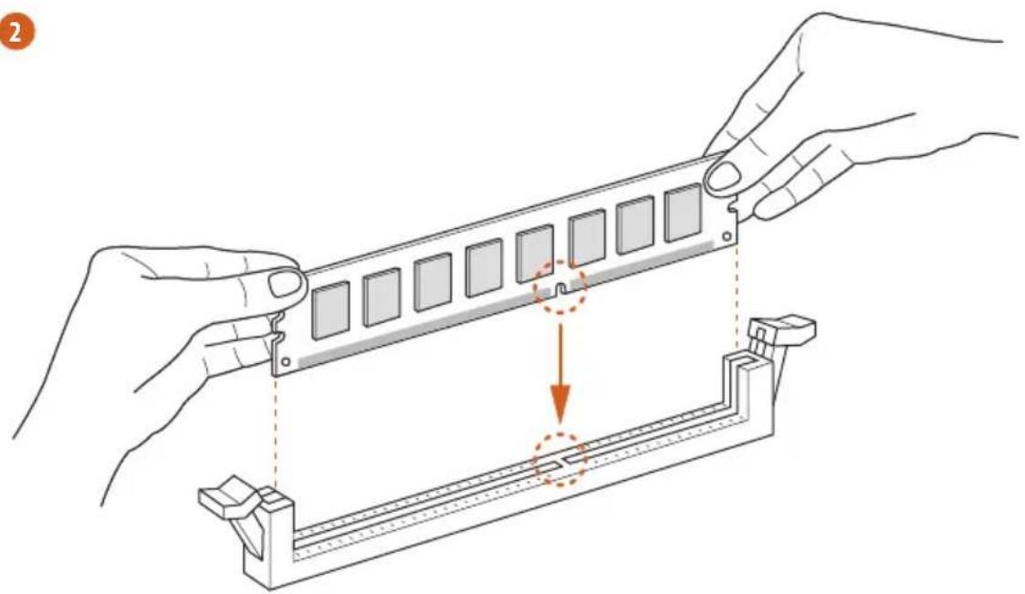
natural_image
Illustration of hands assembling a mechanical component with a highlighted section (no text or symbols)3
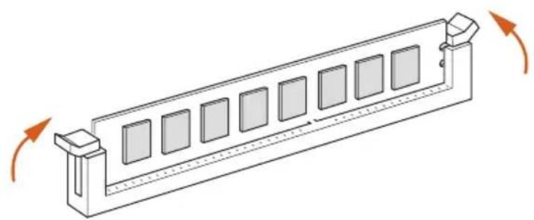
natural_image
Isometric line drawing of a rectangular mechanical component with multiple square slots and directional arrows indicating rotation (no text or symbols)2.4 Expansion Slots (PCI and PCI Express Slots)
There are 2 PCI slots and 4 PCI Express slots on the motherboard.

Before installing an expansion card, please make sure that the power supply is switched off or the power cord is unplugged. Please read the documentation of the expansion card and make necessary hardware settings for the card before you start the installation.
PCI slots:
The PCI1 and PCI2 slots are used to install expansion cards that have 32-bit PCI interface.
PCIe slots:
PCIE1 (PCIe 3.0 x16 slot) is used for PCI Express x16 lane width graphics cards.
PCIE2 (PCIe 2.0 x1 slot) is used for PCI Express x1 lane width cards.
PCIE3 (PCIe 2.0 x16 slot) is used for PCI Express x4 lane width graphics cards.
PCIE4 (PCIe 2.0 x1 slot) is used for PCI Express x1 lane width cards.
PCIe Slot Configurations
PCIE1 PCIE3
Single Graphics Card x16 N/A
Two Graphics Cards in CrossFireX™ Mode
x16 x4

For a better thermal environment, please connect a chassis fan to the motherboard's chassis fan connector (CHA_FAN1 or CHA_FAN2) when using multiple graphics cards.
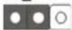
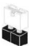
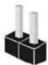
2.5 Jumpers Setup
The illustration shows how jumpers are setup. When the jumper cap is placed on the pins, the jumper is "Short". If no jumper cap is placed on the pins, the jumper is "Open". The illustration shows a 3-pin jumper whose pin1 and pin2 are "Short" when a jumper cap is placed on these 2 pins.
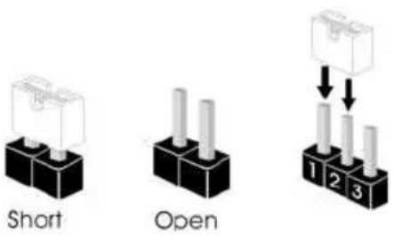
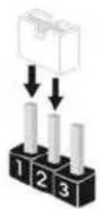
Clear CMOS Jumper (CLRCMOS1)
(see p.1, No. 23)
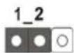
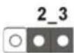
Clear CMOSDefault
CLRCMOS1 allows you to clear the data in CMOS. To clear and reset the system parameters to default setup, please turn off the computer and unplug the power cord from the power supply. After waiting for 15 seconds, use a jumper cap to short pin2 and pin3 on CLRCMOS1 for 5 seconds. However, please do not clear the CMOS right after you update the BIOS. If you need to clear the CMOS when you just finish updating the BIOS, you must boot up the system first, and then shut it down before you do the clear-CMOS action. Please be noted that the password, date, time, and user default profile will be cleared only if the CMOS battery is removed.
2.6 Onboard Headers and Connectors

Onboard headers and connectors are NOT jumpers. Do NOT place jumper caps over these headers and connectors. Placing jumper caps over the headers and connectors will cause permanent damage to the motherboard.
System Panel Header (9-pin PANEL1) (see p.1, No. 18)
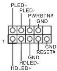
Connect the power switch, reset switch and system status indicator on the chassis to this header according to the pin assignments below. Note the positive and negative pins before connecting the cables.

PWRBTN (Power Switch):
Connect to the power switch on the chassis front panel. You may configure the way to turn off your system using the power switch.
RESET (Reset Switch):
Connect to the reset switch on the chassis front panel. Press the reset switch to restart the computer if the computer freezes and fails to perform a normal restart.
PLED (System Power LED):
Connect to the power status indicator on the chassis front panel. The LED is on when the system is operating. The LED keeps blinking when the system is in S1/S3 sleep state. The LED is off when the system is in S4 sleep state or powered off (S5).
HDLED (Hard Drive Activity LED):
Connect to the hard drive activity LED on the chassis front panel. The LED is on when the hard drive is reading or writing data.
The front panel design may differ by chassis. A front panel module mainly consists of power switch, reset switch, power LED, hard drive activity LED, speaker and etc. When connecting your chassis front panel module to this header, make sure the wire assignments and the pin assignments are matched correctly.
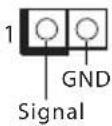
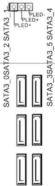
Power LED Header
(3-pin PLED1)
(see p.1, No. 17)
Serial ATA3 Connectors
(SATA3_0:
see p.1, No. 9)
(SATA3_1:
see p.1, No. 11)
(SATA3_2:
see p.1, No. 13)
(SATA3_3:
see p.1, No. 10)
(SATA3_4:
see p.1, No. 12)
(SATA3_5:
see p.1, No. 14)
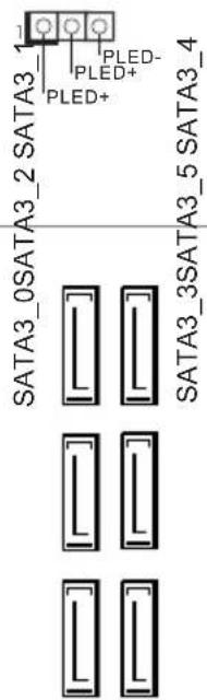
Please connect the chassis power LED to this header to indicate the system's power status.
These six SATA3 connectors support SATA data cables for internal storage devices with up to 6.0 Gb/s data transfer rate. The SATA3_4, SATA3_5 are shared with the SATA Express connector.
Serial ATA Express
Connector
(SATAE_1:
see p.1, No. 15)

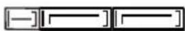
Please connect either SATA or PCIe storage devices to this connector. The SATA Express connector is shared with the SATA3_4, SATA3_5 and the M.2_SSD (NGFF) Socket 3.
*The SATA Express interface is a combination of SATAE_1, SATA3_4, and SATA3_5.
USB 2.0 Headers
(9-pin USB_4_5)
(see p.1, No. 21)
(9-pin USB_6_7)
(see p.1, No. 22)
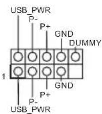
Besides four USB 2.0 ports on the I/O panel, there are two headers on this motherboard. Each USB 2.0 header can support two ports.
USB 3.0 Header (19-pin USB3_4_5) (see p.1, No. 8)
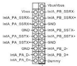
Besides four USB 3.0 ports on the I/O panel, there is one header on this motherboard. Each USB 3.0 header can support two ports.
Front Panel Audio Header (9-pin HD_AUDIO1) (see p.1, No. 27)
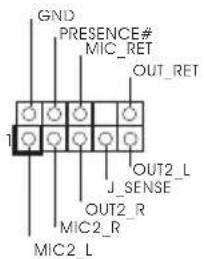
This header is for connecting audio devices to the front audio panel.

- High Definition Audio supports Jack Sensing, but the panel wire on the chassis must support HDA to function correctly. Please follow the instructions in our manual and chassis manual to install your system.
- If you use an AC'97 audio panel, please install it to the front panel audio header by the steps below:
A. Connect Mic_IN (MIC) to MIC2_L.
B. Connect Audio_R (RIN) to OUT2_R and Audio_L (LIN) to OUT2_L.
C. Connect Ground (GND) to Ground (GND).
D. MIC_RET and OUT_RET are for the HD audio panel only. You don't need to connect them for the AC'97 audio panel.
E. To activate the front mic, go to the "FrontMic" Tab in the Realtek Control panel and adjust "Recording Volume".
Chassis Speaker Header (4-pin SPEAKER1) (see p.1, No. 19)
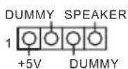
Please connect the chassis speaker to this header.
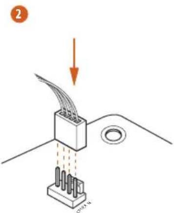
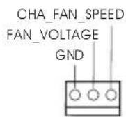
Chassis and Power Fan Connectors (4-pin CHA_FAN1) (see p.1, No. 16)
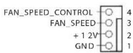
Please connect fan cables to the fan connectors and match the black wire to the ground pin.
(3-pin CHA_FAN2) (see p.1, No. 29)
| (3-pin PWR_FAN1)(see p.1, No. 2) | 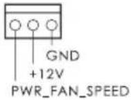 | |
| CPU Fan Connectors(4-pin CPU_FAN1)(see p.1, No. 3) | 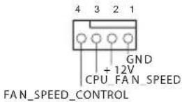 | This motherboard provides a 4-Pin CPU fan (Quiet Fan) connector.If you plan to connect a 3-Pin CPU fan, please connect it to Pin 1-3. |
| (3-pin CPU_FAN2)(see p.1, No. 4) | 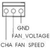 | |
| ATX Power Connector(24-pin ATXPWR1)(see p.1, No. 7) | 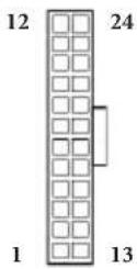 | This motherboard provides a 24-pin ATX power connector. To use a 20-pin ATX power supply, please plug it along Pin 1 and Pin 13. |
| ATX 12V Power Connector(8-pin ATX12V1)(see p.1, No. 1) | 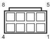 | This motherboard provides an 8-pin ATX 12V power connector. To use a 4-pin ATX power supply, please plug it along Pin 1 and Pin 5. |
| PCIe Power Connector(4-pin PCIE_PWR1)(see p.1, No. 28) | 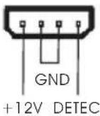 | Please connect a 4 pin molex power cable to this connector when more than three graphics cards are installed. |
| Thunderbolt AIC Connector(5-pin TB1)(see p.1, No. 20) | 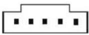 | Please connect a 5-pin signal cable (GPIO cable) to this connector when you install a ThunderboltTM add-in card (AIC). |
Serial Port Header (9-pin COM1) (see p.1, No. 25)
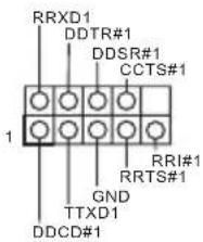
This COM1 header supports a serial port module.
Chassis Intrusion Header (2-pin CI1) (see p.1, No. 24)
This motherboard supports CASE OPEN detection feature that detects if the chassis cove has been removed. This feature requires a chassis with chassis intrusion detection design.
TPM Header (17-pin TPMS1) (see p.1, No. 26)
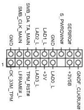
This connector supports Trusted Platform Module (TPM) system, which can securely store keys, digital certificates, passwords, and data. A TPM system also helps enhance network security, protects digital identities, and ensures platform integrity.
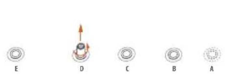
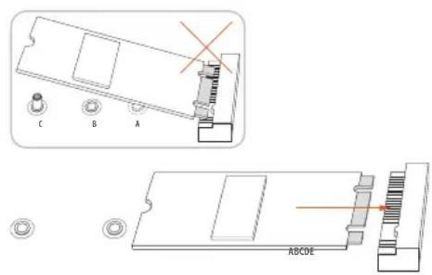
2.7 M.2\_SSD (NGFF) Module Installation Guide
The M.2, also known as the Next Generation Form Factor (NGFF), is a small size and versatile card edge connector that aims to replace mPCIe and mSATA. The M.2_SSD (NGFF) Socket 3 can accommodate either a M.2 SATA3 6.0 Gb/s module or a M.2 PCI Express module up to Gen 2 x2 (10 Gb/s). Please be noted that the M.2_SSD (NGFF) Socket 3 is shared with the SATA Express connector; you can only choose either the M.2_SSD (NGFF) Socket 3 or the SATA Express connector to use.
*The M.2_SSD (NGFF) Socket 3 supports SSD drives. Please note that the WiFi or other non-SSD M.2 modules are not supported.
Installing the M.2\_SSD (NGFF) Module
natural_image
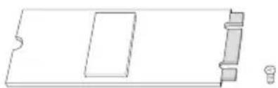
Pure technical line drawing of a mechanical part with no text or symbolsStep 1
Prepare a M.2_SSD (NGFF) module and the screw.
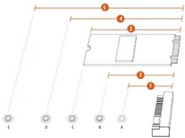
Step 2
Depending on the PCB type and length of your M.2_SSD (NGFF) module, find the corresponding nut location to be used.
No.12345
| Nut Location A B C D E | |||||
| PCB Length | 3cm | 4.2cm | 6cm | 8cm | 11cm |
| Module Type | Type2230 | Type 2242 | Type2260 | Type 2280 | Type 22110 |
natural_image
Five circular diagrams labeled A through E, showing different mechanical or structural configurations without any text or symbols.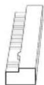
Step 3
Move the standoff based on the module type and length.
The standoff is placed at the nut location D by default. Skip Step 3 and 4 and go straight to Step 5 if you are going to use the default nut. Otherwise, release the standoff by hand.
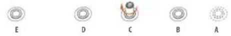
Step 4
Peel off the yellow protective film on the nut to be used. Hand tighten the standoff into the desired nut location on the motherboard.
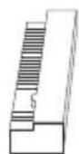
Step 5
Align and gently insert the M.2 (NGFF) SSD module into the M.2 slot. Please be aware that the M.2 (NGFF) SSD module only fits in one orientation.
natural_image
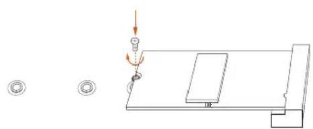
Pure technical diagram showing a mechanical assembly with no text, numbers, or symbolsStep 6
Tighten the screw with a screwdriver to secure the module into place. Please do not overtighten the screw as this might damage the module.
M.2\_SSD (NGFF) Module Support List
PCIe Interface SATA Interface
Plector PX-AG256M6e ADATA AXNS381E-128GM-B
Plextor PX-AG512M6e ADATA AXNS381E-256GM-B
SanDisk SD6PP4M-128G Crucial CT120M500SSD4/120G
SanDisk SD6PP4M-256G Crucial CT240M500SSD4/240G
Samsung XP941-512G (MZHPU512HCGL) Intel SSDSCKGW080A401/80G
Kingston RBU-SNS8400S3/180GD
For the latest updates of M.2_SSD (NFGG) module support list, please visit our website for details: http://www.asrock.com
1 Einleitung
Serial-ATA-III-Anschlüsse
(SATA3_0:
siehe S. 1, Nr. 9)
(SATA3_1:
siehe S. 1, Nr. 11)
(SATA3_2:
siehe S. 1, Nr. 13)
(SATA3_3:
siehe S. 1, Nr. 10)
(SATA3_4:
siehe S. 1, Nr. 12)
(SATA3_5:
siehe S. 1, Nr. 14)
RAID 1, RAID 5, RAID 10, Intel Rapid Storage Technology 13 e Intel Smart Response Technology), NCQ, AHCI e Hot Plug
SATA3_5 e Socket 3 M.2_SSD (NGFF))
6,0 Gb/s ed il modulo M.2 PCI Express fino a Gen2 x2 (10 Gb/s)
Connet- tore
(OC)/2400(OC)/2133(OC)/1866(OC)/1600/1333/1066
Non-ECC Unbuffered
«ПРЕДОСТЕРЕЖЕНИЕ»)
(XMP)1.3/1.2
Слот
расширения
64-bit / 7 32-bit / 7 64-bit
Сертификация
6,0 Gb/s e módulo M.2 PCI Express até Gen2 x2 (10 Gb/s)
Conector
/ 7 32-bit / 7 64-bit
Certifi-
cações
necessária)
Apagar o Jumper CMOS (CLRCMOS1)
(ver p.1, N.° 23)

Padrão


Apagar CMOS
5, RAID 10, Intel Rapid Storage Technology 13 ve Intel Smart Response Technology), NCQ, AHCI ve Tak Çıkar destekler
natural_image
Simple graphic with a magnifying glass icon and a horizontal line, no text or symbols present.1.1 パッケージの内容

1.2 仕様
^TM MOSFET
ASRock Cloud
CPU
TM
TM
TM
TM
TM
HDMI
LAN
, Kloudian Orbweb.ME Professional (Win 8.1)
os
64-bit / 7 32-bit / 7 64-bit


1.3 ジャンパー設定
Short
Open
(CLRCMOS1)
1 2

2 3

ASRock Full Spike Protection
ASRock Cloud
ASRock APP Shop
CPU
Core ^TM (Socket 1150)
Chipset
Memori
/1866(OC)/1600/1333/1066 non-ECC, memori tanpa buffer
Slot Ek- spansi
If you need to contact ASRock or want to know more about ASRock, you're welcome to visit ASRock's website at http://www.asrock.com; or you may contact your dealer for further information. For technical questions, please submit a support request form at http://www.asrock.com/support/tsd.asp
ASRock Incorporation
2F., No.37, Sec. 2, Jhongyang S. Rd., Beitou District,
Taipei City 112, Taiwan (R.O.C.)
ASRock EUROPE B.V.
Bijsterhuizen 3151
6604 LV Wijchen
The Netherlands
Phone: +31-24-345-44-33
Fax: +31-24-345-44-38
ASRock America, Inc.
13848 Magnolia Ave, Chino, CA91710
U.S.A.
Phone: +1-909-590-8308
Fax: +1-909-590-1026