
SH1000R - Turntable TECHNICS - Free user manual and instructions
Find the device manual for free SH1000R TECHNICS in PDF.
| Product Type | Special plinth base for SP-10R turntable |
| Dimensions (without cover) | 524 × 97 × 392 mm (L × H × D) |
| Dimensions (with cover) | 531 × 188 × 399 mm (L × H × D) |
| Weight (without cover) | Approximately 18.0 kg |
| Weight (with cover) | Approximately 20.2 kg |
| Cabinet materials | Aluminum and bulk molding compound (BMC) – five-layer high-rigidity structure |
| Isolator material | High-damping silicone rubber |
| Included accessories | Protective cover, hex key, isolator attachments (4 pieces), screw set for SP-10R (screws, washers, Belleville springs – 9 pieces) |
| Main functions | Total anti-vibration design; mechanical isolation from external vibrations |
| Tonearm compatibility | Short tonearms (Ortofon AS-212S, RS-212D; Technics EPA-100mk2; JELCO SA-250; SME M2-9R) via SH-TB10 base (sold separately) |
| Safety | Use only on a flat and stable surface; always two people for unpacking and transport; keep small parts out of reach of children |
| Care and cleaning | Clean with a soft dry cloth; do not use solvents or abrasive products |
| Warranty (Canada) | 3 years parts and labor |
| Spare parts and repairability | Repair by a Panasonic authorized service center; parts available through the service network |
| General information | Designed exclusively for the SP-10R motor; height adjustment via isolators; uses a chassis ground (optional) to reduce noise |
Frequently Asked Questions - SH1000R TECHNICS
User questions about SH1000R TECHNICS
0 question about this device. Answer the ones you know or ask your own.
Ask a new question about this device
Download the instructions for your Turntable in PDF format for free! Find your manual SH1000R - TECHNICS and take your electronic device back in hand. On this page are published all the documents necessary for the use of your device. SH1000R by TECHNICS.
USER MANUAL SH1000R TECHNICS
natural_image
3D rendering of a rectangular electronic device casing with a circular recess and side slot (no text or symbols)SH-1000R
ターンテーブルベース
Turntable Base
Base de plateau
Plattentellerbasis
Base de platine
Base per Giradischi
Operating Instructions
natural_image
Two individuals examining a mechanical component (no text or symbols visible)持ち上げ作業イメージ図
機器の組み立て
組み立てる前に
natural_image
Diagram of a CD or DVD disc with labeled parts and a stand (no text or symbols present)脱着ハンドル取付穴
natural_image
Technical diagram of a mechanical testing setup with rotating components and base supports (no text or symbols)包装クッション
natural_image
Top-down view of a mechanical component with circular features and mounting holes (no text or symbols visible)natural_image
Top-down view of a mechanical component with circular features and mounting holes (no text or symbols)7 インシュレーターを取り付ける。
natural_image
Illustration of a hand operating a circular device with a lid and switch (no text or symbols visible)設置
本体の設置
natural_image
Diagram of a vintage radio with a flat top and stand, enclosed in a transparent enclosure (no text or symbols)お願い
Help desk for foreign residents in Japan
Tokyo (03) 3256-5444 Osaka (06) 6645-8787
Open:9:00-17:30(closed on Saturdays/Sundays/national holidays)
Thank you for purchasing this product.
This product is a special turntable base for SP-10R. Please read these instructions carefully before using this product, and save this manual for future use.
Features
Thorough anti-vibration designed cabinet and insulator
- The high-rigidity cabinet is composed of different types materials such as aluminum and BMC.
- Silicon rubber with high damping characteristics and excellent long-term reliability is used in the insulator to shut out external vibration.
For the U.S.A. and Canada
If you have any questions, visit:
U.S.A.: http://shop.panasonic.com/support
Canada: www.panasonic.ca/english/support
Register online at
http://shop.panasonic.com/support (U.S. customers only)
For the United Kingdom and Ireland customers
Sales and Support Information
Customer Communications Centre
- For customers within the UK: 0333 222 8777
• For customers within Ireland: 01 447 5229 - Monday–Friday 9:00 am – 5:00 pm, (Excluding public holidays).
- For further support on your product, please visit our website: www.technics.com/uk/
Table of contents
Accessories....02
Specifications 02
Parts Name....03
Safety precautions 03
Unpacking and preparation 04
Putting the player together....05
Installation....08, 100
Accessories
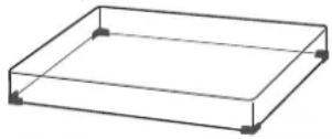
Dust cover (1 pc.) (TXP0046)

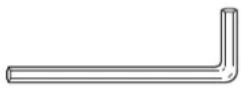
Hex wrench (1 pc.) (TTK0004)
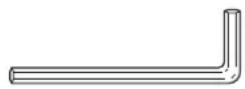
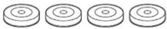
Insulator attachment (4 pc.) (TEKL021)
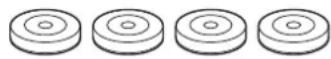
Screw set for SP-10R (1 set) (TTV0113)
- Screws
- Washers
- Belleville springs (9 pc.)
- Please check and identify the supplied accessories.
- Keep the packaging materials after taking out the goods.
(9) You will need them when carrying the product for a long distance. pc.)
- Keep screws, washers and belleville springs out of reach of children to prevent swallowing.
Specifications
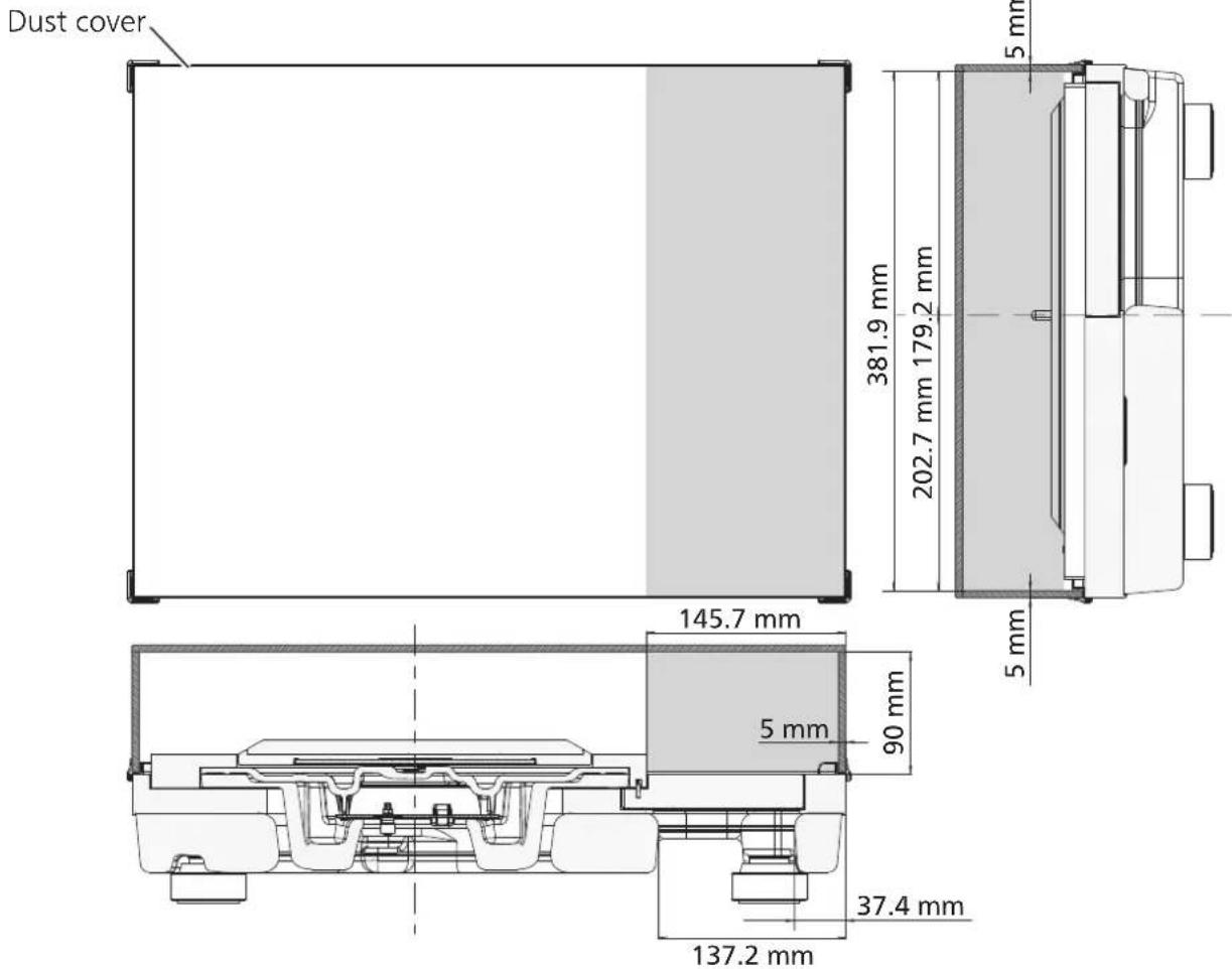
| Dimensions | Main unit without dustcover 524×97×392 mm (W×H×D)(20-21/32 × 6-13/16 × 15-7/16 inch) |
| Main unit with dustcover 531×188×399 mm (W×H×D)(20-29/32 × 7-13/32 × 15-23/32 inch) | |
| Mass | Main unit without dustcover Approx. 18.0 k g |
| Main unit with dustcover Approx. 20.2 k g |
Parts Name
Position for mounting the SP-10R main unit
- Do not attach insulators here when mounting the SP-10R main unit. Doing so may result in noise.
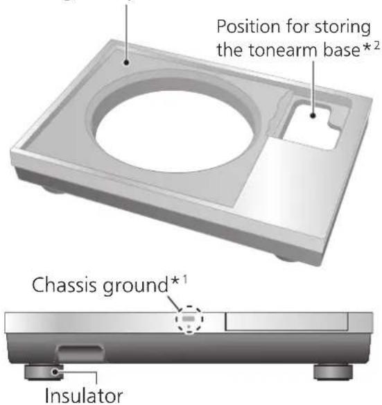
*1 Chassis ground
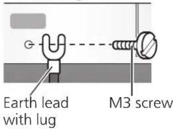
M3 screw (Coarse thread)
13 mm or less

Basically, there is no need to connect the chassis ground.
If you are concerned about the noise, connect as described below. The noise may decrease though it depends on your environment of use.
① Using a commercially available M3 screw, attach an earth lead with lug to the chassis ground.
②Connect the earth lead to the earth terminal on the amplifier.
- Use a conductive screw.
*2 The tonearm base that is mounted on the standard position (⇒05) for mounting the tonearm base on the SP-10R main unit can be stored here.
Safety precautions
Warning
- Do not put small parts within the reach of small children.
Accidental swallowing of such an item has a harmful effect on the body.
- In the event that such an item has been swallowed, consult a doctor immediately.
Caution
- Place this unit on an even surface.
Do not install the product at a high place, uneven place, or place with vibration or impact.
-The product may turn over or fall, resulting in injury.
- Do not put a heavy thing on the product or do not step on the product.
-The product may turn over or fall, resulting in injury.
- Do not place sources of naked flames, such as lighted candles, on this unit.
- Do not install the product in an extremely high temperature.
The outer case and internal parts may be deteriorated.
-Observe the temperature if the product is exposed to direct sunlight or installed near a heater.
● Always use two people or more to install or move the unit.
- Doing so may cause this unit to fall, resulting in personal injury or malfunction of this unit.
- Be careful not to have your fingers caught by the dust cover.
Otherwise your fingers may be injured.
-Particularly keep an eye on a child.
Unpacking and preparation
Notes for taking out the goods from the package box and transporting
Attention
● Always use two or more people to take out and transport the main unit.
- Be careful not to lose balance if lifting the unit with your hands at non-optimal position.
- You may damage your back.
- You may lose balance on the stairs and the like, which may lead to injury.
- Be careful not to catch your fingers when taking out the main unit.
- Be careful not to catch your fingers in the gap between the bottom of the main unit and floor.
- Keep the packaging materials after taking out the goods. Pack the product in the reverse order of unpacking before carrying it to a far place, for example when moving to another house.
● Take out the goods after deciding the installation location
- For notes regarding installation, see "Installation" (⇒08).
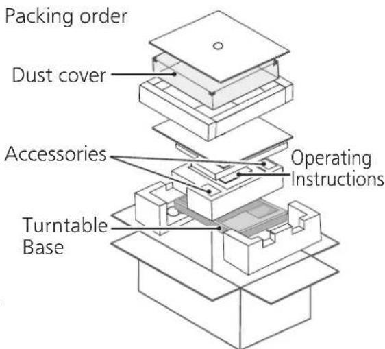
① Take out the dust cover and operating instructions.
- Keep accessories out children's reach.
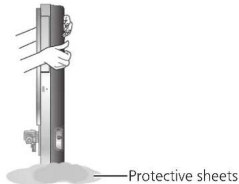
● The turntable base and dust cover are wrapped in protective sheets.
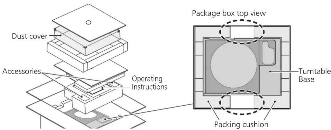
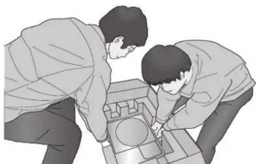
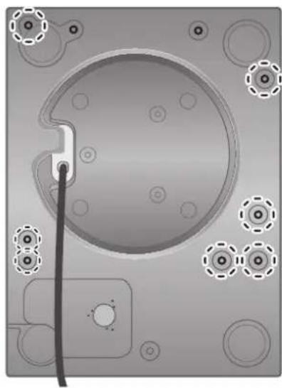
②Put your hands between the packing cushions (①dotted line area of the package box top view) and slowly lift the main unit to take it out.
Always perform this task using two or more people.
- Be very careful when lifting the main unit.
- Hold the main unit from the bottom to prevent it from slipping from your hands.
• Perform the task using both hands to not lose balance.
natural_image
Two people examining a mechanical component with a circular feature (no text or symbols visible)Lifting task image
Putting the player together
Before putting the player together
- For how to assemble or remove the turntable, see the SP-10R operating instructions.
- Use the tonearm base (SH-TB10) sold separately when mounting a tone arm. For details on how to mount, see the operating instructions of the tone arm to be mounted.
Select a short-type tonearm base from the model numbers listed below when mounting it on the standard position for mounting the tonearm base.
To mount SH-TB10-S on the standard position for mounting the tonearm base, see the section of installation ( 100).
| Tonearm base | Tone arm (Short-type) | |
| Manufacturer | Model number | |
| SH-TB10RT1-S ortofon AS-212S, RS-212D | ||
| SH-TB10TC1-S Technics EPA-100mk2 | ||
| SH-TB10JL1-S JELCO | SA-250 | |
| SH-TB10SM1-S SME | M2-9R | |
Mount the tone arm on the SP-10R main unit
1 Mount your tone arm to the tonearm base.
- Refer to your tone arm leaflet.
2 Mount the tonearm base on the SP-10R main unit.
- Mount in the appropriate location.
- Fit the projections and screw holes of the tonearm base in the SP-10R main unit and tighten it (at three locations) with the mounting screws and washers supplied with the tonearm base using the hex wrench.
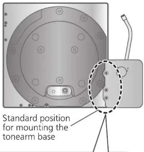

Insert the pin on the tonearm base into the pin hole to position.
Putting the player together (continued)
Mounting on the turntable base
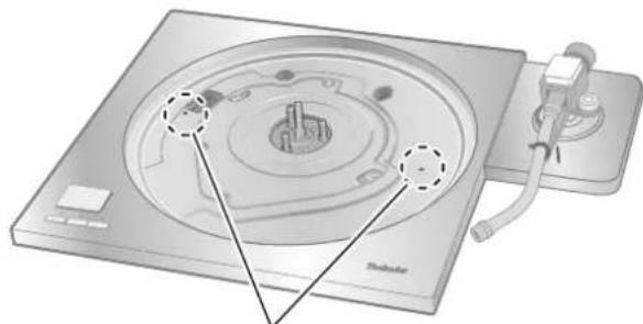
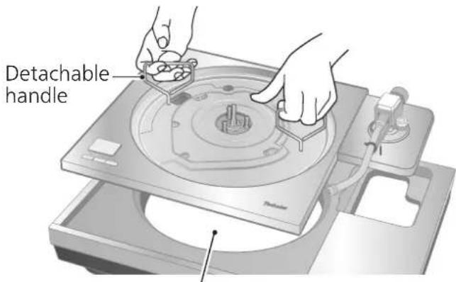
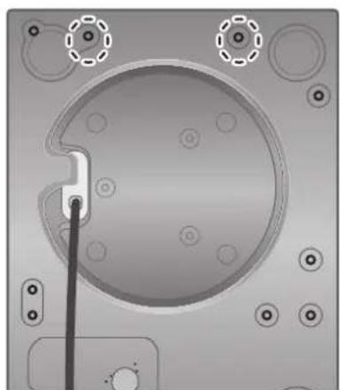
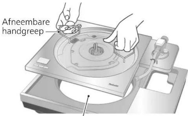
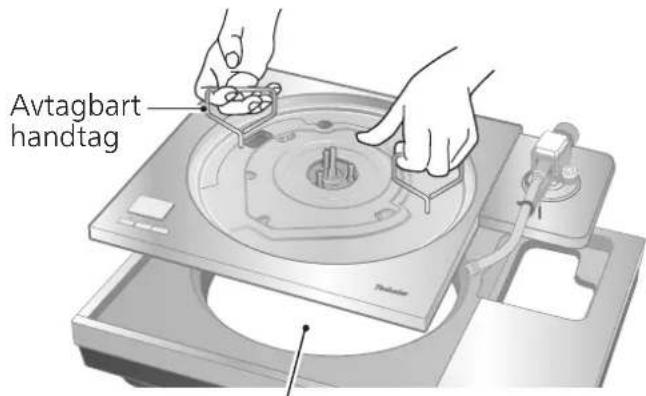
1 Tighten the detachable handle screws supplied with SP-10R into the detachable handle mounting holes (at two locations) on the SP-10R main unit.
Attention
- Tighten the detachable handle by turning it 5 or more times. If you have tightened it until the end, loose a little bit. Do not tighten it firmly.
2 Slowly lift the SP-10R main unit and place it on the turntable base.
- Be careful not to catch the control unit connection cable.
natural_image
Diagram of a CD or DVD disc with labeled parts and a stand (no text or symbols present)Detachable handle mounting hole
Pass the control unit connection cable through the hole on the turntable base.
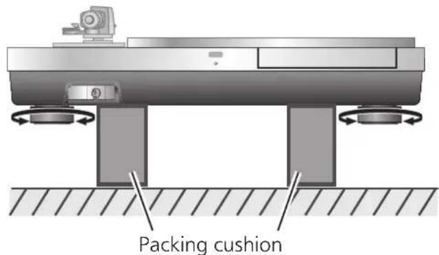
3 Remove the insulators.
- Place two packing cushions under the main unit to lift it, and turn the insulators counterclockwise (to the left hand) when seen from below.
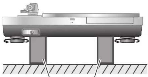
natural_image
Technical diagram of a mechanical assembly with rotating components and base supports (no text or symbols)Packing cushion
4 Place one packing cushion under the main unit to put it at an angle to tighten the screw set for SP-10R using the accessory hex wrench.
(The two locations indicated in the figure right)
- Attach the screw, washer and belleville spring in the order as shown below.
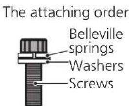
natural_image
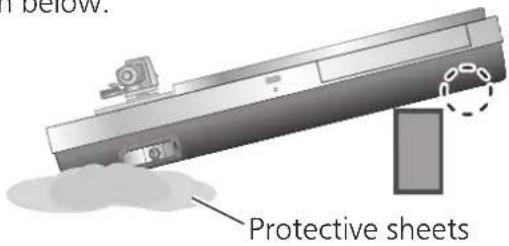
Top-down view of a mechanical component with circular features and mounting holes (no text or symbols visible)5 Put the main unit vertically on a side on the protective sheet that came with the main unit.
● Make sure there are no protruding objects, such as screws, under the protective sheet.
- Be careful the main unit does not lose balance and tip over.
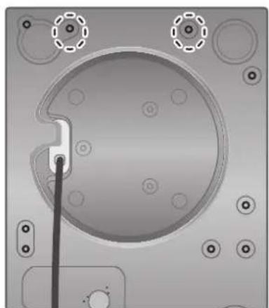
6 Tighten the screw set for SP-10R using the accessory hex wrench. (The seven locations indicated in the figure right)
- Check that all nine screws including the two tightened in step 4 have been firmly tightened.
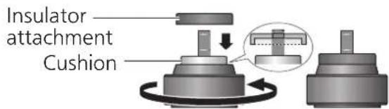
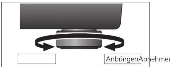
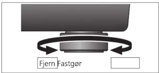
7 Attach the insulators to the unit.
- Place two packing cushions under the main unit to lift it, and turn the insulators clockwise (to the right hand) when seen from below.
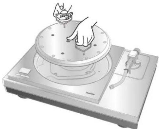
8 Mount the turntable on the SP-10R main unit.
- See "Fitting the turntable" in the SP-10R operating instructions.
natural_image
Top-down view of a mechanical component with circular features and mounting holes (no text or symbols)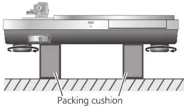

natural_image
Illustration of a hand pressing down on a circular mechanical device with a lid and base (no text or symbols)Installation
Install the unit on a horizontal surface protected from vibrations.
Keep this unit as far as possible from speakers.
*See "Notes for installation" as well in the SP-10R operating instructions.
- If the unit rattles when installed, adjust by inserting insulators. ( below)
- Do not draw the unit forcibly after installation. Doing so may damage the insulator or floor surface.
• Always use two people or more to perform the task.
Adjusting the height to make the unit horizontal
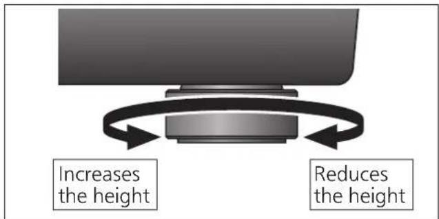
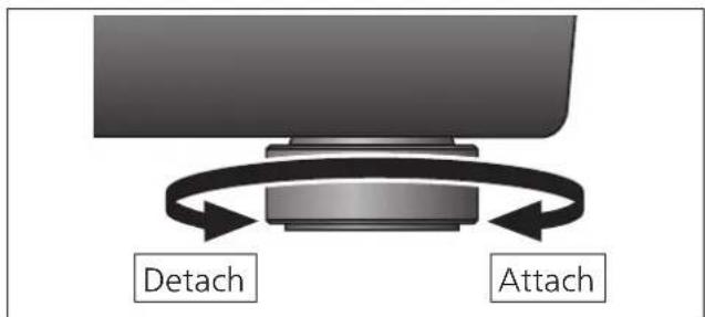
1 Raise the main unit to turn the insulators and adjust the height.
- Clockwise (to the right hand) when seen from below: Lowered
- Counter-clockwise (to the left hand) when seen from below: Raised
Attention
- Do not turn the insulators too far.
Doing so may cause them to come off or damage them.
Insulator attachment
It is recommended that the unit be used without the insulator attachments normally.
Use the insulator attachments according to the installation environments or your preference.
- Vibration absorption is disabled and the structure becomes rigid when the insulator attachments are attached.
- Howling may occur in some installation environments.
- Howling may occur as a result of attaching insulator attachments.
1 Remove the insulators.
- Perform the task by placing the packing cushion or the like under the unit.
2 Attach the insulator attachment by screwing it on the insulator.
- This makes the insulator lose its cushioning function.
3 Attach the insulators.
Attention
- Be careful not to lose balance.
08 (18)
English
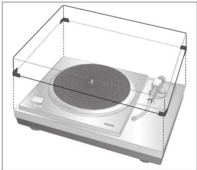
Fit the dust cover
1 While holding the dust cover from both sides, put it in place by aligning its four corners with the four corners of the unit.
- When removing, lift the dust cover straight up.
The combination of the following tonearm base and tone arm will cause interference with the dust cover. Therefore, remove the dust cover.
| Tonearm base | Tone arm (Short-type) | |
| Manufacturer | Model number | |
| SH-TB10JL1-S J | ELCO SA-250 | |
natural_image
Illustration of a vintage radio with a circular head and speaker, enclosed in a transparent enclosure (no text or symbols)Attention
- Do not use the dust cover if you have a second tone arm connected.
-
Remove the dust cover while playing.
-
Clearance for installing the dust cover (☐: Clearance)
Introduction
Installation....08, 100
Accessoires
| Couvercle (1 pc.) (TXP0046) | Clé hexagonale (1 pc.) (TTK0004) | Accessoire isolant (4 pc.) (TEKL021) |
 |  |  |
natural_image
Diagram of a mechanical assembly with two screws and a U-shaped component, no text or symbols presentnatural_image
Two individuals examining a mechanical component or device (no visible text or symbols)natural_image
Technical diagram of a mechanical component with circular features and a dashed circle highlighting a specific area (no text or symbols present)natural_image
Technical diagram showing mechanical assembly with arrows indicating direction and components (no text or symbols)natural_image
Diagram of a CD or DVD disc with labeled components and a stand (no text or symbols present)natural_image
Technical diagram of a mechanical assembly with mounting base and support legs (no text or symbols)Coussin d'emballage
natural_image
Top-down view of a mechanical component with circular features and mounting holes (no text or symbols visible)natural_image
Top-down view of a mechanical component with circular features and mounting holes (no text or symbols)natural_image
Illustration of a hand pressing down on a circular mechanical device with a lid and base (no text or symbols)Installation
natural_image
3D rendering of a vintage radio with a circular head and speaker, enclosed in a transparent enclosure (no text or symbols visible)Attention
natural_image
Two individuals examining a mechanical component or device (no visible text or symbols)natural_image
Diagram of a CD or DVD disc with labeled parts and a stand (no text or symbols present)natural_image
Technical diagram of a mechanical testing setup with two supports and a central platform (no text or symbols)Verpackungspolster
natural_image
Top-down view of a mechanical component with circular features and mounting holes (no text or symbols)natural_image
Top-down view of a mechanical component with circular features and mounting holes (no text or symbols)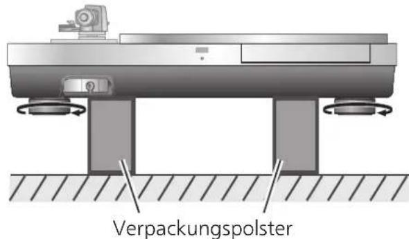
natural_image
Illustration of a hand operating a circular mechanical device with a knob, mounted on a base (no text or symbols visible)Aufstellung
Aufstellung
natural_image
Technical diagram of a mechanical assembly with rotating components and base supports (no text or symbols)Verpackungspolster
natural_image
3D rendering of a vintage radio with a circular head and speaker, enclosed in a transparent enclosure (no text or symbols visible)Achtung
natural_image
Pure mechanical diagram showing a U-shaped clamp and a screw connected by dashed lines, without any text or symbolsnatural_image
Two individuals examining a mechanical component or device (no visible text or symbols)natural_image
Diagram of a CD or DVD disc with labeled parts and a stand (no text or symbols present)natural_image
Technical diagram of a mechanical assembly with two base supports and a central platform (no text or symbols)Coussin d'emballage
natural_image
Top-down view of a mechanical component with circular features and mounting holes (no text or symbols visible)natural_image
Top-down view of a mechanical component with circular features and mounting holes (no text or symbols)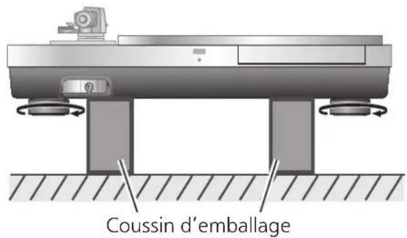

natural_image
Illustration of a hand pressing down on a circular mechanical device with a knob (no text or symbols visible)Installation
natural_image
Technical diagram of a mechanical assembly with rotating components and base supports (no text or symbols)Coussin d'emballage
natural_image
3D rendering of a vintage radio with a circular head and speaker, enclosed in a transparent enclosure (no text or symbols visible)Attention
natural_image
Diagram of a mechanical assembly with two components, one showing a U-shaped component and the other a bolt connected by a dashed line (no text or symbols)natural_image
Two individuals examining a mechanical component or device (no visible text or symbols)natural_image
Diagram of a CD or DVD disc with labeled parts and a stand (no text or symbols present)natural_image
Technical diagram of a mechanical testing setup with rotating components and base supports (no text or symbols)natural_image
Top-down view of a mechanical component with circular features and mounting holes (no text or symbols visible)natural_image
Top-down view of a mechanical component with circular features and mounting holes (no text or symbols)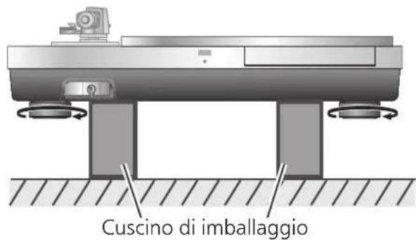
natural_image
Illustration of a hand pressing down on a circular mechanical device with a handle (no text or symbols visible)Installazione
natural_image
Mechanical assembly diagram showing a rotating platform with base and supports, no text or symbols presentnatural_image
3D rendering of a vintage typewriter with a circular top and speaker, enclosed in a transparent enclosure (no text or symbols visible)Attenzione
natural_image
Two people working on a mechanical device with no visible text or symbolsnatural_image
Mechanical assembly diagram showing gear and housing components with directional arrows (no text or labels)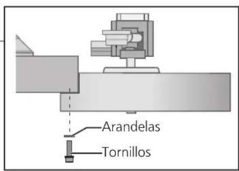
natural_image
Diagram of a CD or DVD disc with labeled parts and a stand (no text or symbols present)natural_image
Technical diagram of a mechanical testing setup with base and support components (no text or symbols)Cojín de embalaje
natural_image
Top-down view of a mechanical component with circular features and mounting holes (no text or symbols visible)natural_image
Top-down view of a mechanical component with circular features and mounting holes (no text or symbols)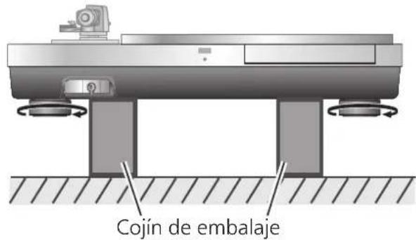
natural_image
Illustration of a hand pressing down on a circular mechanical device with a handle (no text or symbols visible)Instalación
natural_image
3D rendering of a vintage radio with a circular head and speaker, enclosed in a transparent enclosure (no text or symbols visible)Atención
natural_image
Two people examining a mechanical component (no text or symbols visible)natural_image
Diagram of a CD or DVD disc with labeled parts and a stand (no text or symbols present)natural_image
Technical diagram of a mechanical assembly with two base supports and a central platform (no text or symbols)Emballeringspude
natural_image
Top-down view of a mechanical component with circular features and mounting holes (no text or symbols)natural_image
Top-down view of a mechanical component with circular features and a central hub (no text or symbols)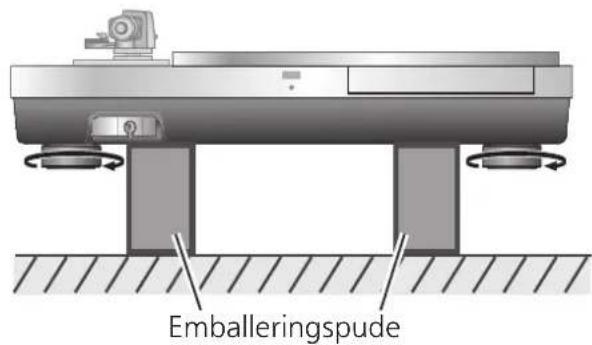

natural_image
Illustration of a hand pressing down on a circular mechanical device with a handle (no text or symbols visible)Opstilling
Montér støvlåget
natural_image
3D rendering of a vintage radio with a disc and stand, enclosed in a transparent enclosure (no text or symbols visible)Bemærk
natural_image
Two people examining a mechanical component or device (no visible text or symbols)natural_image
Diagram of a CD or DVD disc with labeled parts and mounting bracket (no text or symbols present)Afneembare handgreep montagegat
natural_image
Technical diagram of a mechanical assembly with rotating components and base supports (no text or symbols)Verspakkingskussen
natural_image
Top-down view of a mechanical component with circular features and mounting holes (no text or symbols)5
natural_image
Top-down view of a mechanical component with circular features and mounting holes (no text or symbols)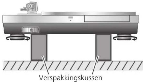

natural_image
Illustration of a hand operating a circular disc on a machine (no text or symbols visible)Installeren
natural_image
Diagram of a radio receiver with a speaker and antenna, enclosed in a transparent enclosure (no text or symbols)Aandacht
Installering....08, 100
Tillbehör
natural_image
Pure mechanical diagram showing a U-shaped component connected to a screw, with no text or symbols present.natural_image
Two people examining a mechanical component (no text or symbols visible)natural_image
Diagram of a CD or DVD disc with labeled parts and a central hub, showing no text or symbols.Monteringshål för avtagbart handtag
natural_image
Top-down view of a mechanical component with circular features and mounting holes (no text or symbols visible)natural_image
Top-down view of a mechanical component with circular features and mounting holes (no text or symbols)

natural_image
Illustration of a hand pressing down on a circular mechanical device with a flame (no text or symbols)Installing
natural_image
Diagram of a vintage typewriter with a circular top and speaker, enclosed in a transparent enclosure (no text or symbols)Observera
natural_image
Two people examining a mechanical component or tool (no text or symbols visible)Kuva nostamisesta
natural_image
Diagram of a CD or DVD disc with labeled parts and a stand (no text or symbols present)natural_image
Technical diagram of a mechanical testing setup with two supports and a central platform (no text or symbols)Pakkauspehmuste
natural_image
Top-down view of a mechanical component with circular features and mounting holes (no text or symbols)natural_image
Top-down view of a mechanical component with circular features and mounting holes (no text or symbols)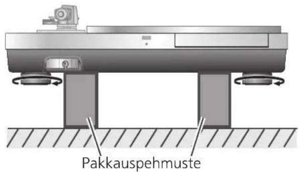

natural_image
Illustration of a hand operating a circular mechanical device with a knob, mounted on a base (no text or symbols visible)Aennus
Insulator attachment
natural_image
Diagram of a vintage radio with a stand and speaker, enclosed in a transparent enclosure (no text or symbols)Huomio
natural_image
Two people examining a mechanical component or device (no visible text or symbols)natural_image
Diagram of a CD or DVD disc with labeled parts and a stand (no text or symbols present)natural_image
Technical diagram of a mechanical testing setup with base and mounting components (no text or symbols)natural_image
Top-down view of a mechanical component with circular features and mounting holes (no text or symbols visible)natural_image
Top-down view of a mechanical component with circular features and mounting holes (no text or symbols)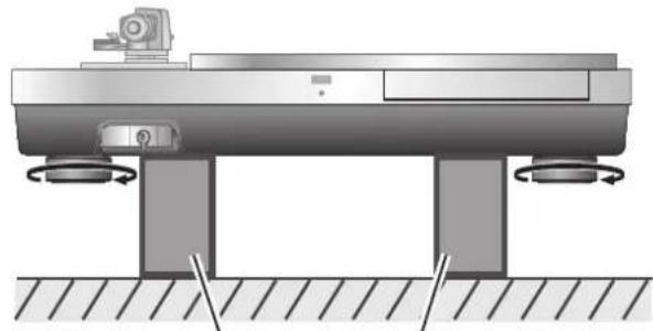
natural_image
Mechanical assembly diagram showing a rotating platform with base and supports, no text or symbols presentnatural_image
Illustration of a hand operating a circular device with a lid and switch (no text or symbols visible)Instalacja
natural_image
Diagram of a radio receiver with a speaker and antenna, enclosed in a transparent enclosure (no text or symbols)Uwaga
Installation English
Aufstellung Deutsch
Limited Warranty (ONLY FOR U.S.A.)
Technics Products – Limited Warranty
Limited Warranty Coverage (For USA Only)
If your product does not work properly because of a defect in materials or workmanship, Panasonic Corporation of North America (referred to as "the warrantor") will, for the length of the period indicated on the chart below, which starts with the date of original purchase ("warranty period"), at its option either (a) repair your product with new or refurbished parts, (b) replace it with a new or a refurbished equivalent value product, or (c) refund your purchase price. The decision to repair, replace or refund will be made by the warrantor.
| Product or Part Name | Parts | Labor |
| Technics Turntable Base (SH-1000R) | 3(three)years | 3(three)years |
During the "Labor" warranty period there will be no charge for labor. During the "Parts" warranty period, there will be no charge for parts. This Limited Warranty excludes both parts and labor for non-rechargeable batteries, antennas, and cosmetic parts (cabinet). This warranty only applies to products purchased and serviced in the United States. This warranty is extended only to the original purchaser of a new product which was not sold "as is".
Mail-In Service--Online Repair Request
Online Repair Request
To submit a new repair request and for quick repair status visit our Web Site at http://shop.panasonic.com/support
When shipping the unit, carefully pack, include all supplied accessories listed in the Owner's Manual, and send it prepaid, adequately insured and packed well in a carton box. When shipping Lithium Ion batteries please visit our Web Site at http://shop.panasonic.com/support as Panasonic is committed to providing the most up to date information. Include a letter detailing the complaint, a return address and provide a daytime phone number where you can be reached. A valid registered receipt is required under the Limited Warranty.
IF REPAIR IS NEEDED DURING THE WARRANTY PERIOD, THE PURCHASER WILL BE REQUIRED TO FURNISH A SALES RECEIPT/PROOF OF PURCHASE INDICATING DATE OF PURCHASE, AMOUNT PAID AND PLACE OF PURCHASE. CUSTOMER WILL BE CHARGED FOR THE REPAIR OF ANY UNIT RECEIVED WITHOUT SUCH PROOF OF PURCHASE.
Limited Warranty Limits and Exclusions
This warranty ONLY COVERS failures due to defects in materials or workmanship, and DOES NOT COVER normal wear and tear or cosmetic damage. The warranty ALSO DOES NOT COVER damages which occurred in shipment, or failures which are caused by products not supplied by the warrantor, or failures which result from accidents, misuse, abuse, neglect, mishandling, misapplication, alteration, faulty installation, set-up adjustments, misadjustment of consumer controls, improper maintenance, power line surge, lightning damage, modification, introduction of sand, humidity or liquids, commercial use such as hotel, office, restaurant, or other business or rental use of the product, or service by anyone other than a Factory Service Center or other Authorized Servicer, or damage that is attributable to acts of God.
The model number and serial number of this product can be found on either the back or the bottom of the unit. Please note them in the space provided below and keep for future reference.
MODEL NUMBER SH-1000R
SERIAL NUMBER
THERE ARE NO EXPRESS WARRANTIES EXCEPT AS LISTED UNDER "LIMITED WARRANTY COVERAGE". THE WARRANTOR IS NOT LIABLE FOR INCIDENTAL OR CONSEQUENTIAL DAMAGES RESULTING FROM THE USE OF THIS PRODUCT, OR ARISING OUT OF ANY BREACH OF THIS WARRANTY.
(As examples, this excludes damages for lost time, travel to and from the servicer, loss of or damage to media or images, data or other memory or recorded content. The items listed are not exclusive, but for illustration only.)
ALL EXPRESS AND IMPLIED WARRANTIES, INCLUDING THE WARRANTY OF MERCHANTABILITY, ARE LIMITED TO THE PERIOD OF THE LIMITED WARRANTY.
Some states do not allow the exclusion or limitation of incidental or consequential damages, or limitations on how long an implied warranty lasts, so the exclusions may not apply to you.
This warranty gives you specific legal rights and you may also have other rights which vary from state to state. If a problem with this product develops during or after the warranty period, you may contact your dealer or Service Center. If the problem is not handled to your satisfaction, then write to:
Consumer Affairs Department
Panasonic Corporation of North America
661 Independence Pkwy
Chesapeake, VA 23320
PARTS AND SERVICE, WHICH ARE NOT COVERED BY THIS LIMITED WARRANTY, ARE YOUR RESPONSIBILITY.
Shop Accessories!
for all your Technics gear
Go to
http://shop.panasonic.com/support
Get everything you need to get the most out of your Technics products
Accessories & Parts for your Camera, Phone, A/V products, TV, Computers & Networking, Personal Care, Home Appliances, Headphones, Batteries, Backup Chargers & more...
Customer Services Directory
For Product Information, Operating Assistance, Parts, Owner's Manuals, Dealer and Service info go to http://shop.panasonic.com/support
For the hearing or speech impaired TTY: 1-877-833-8855
As of July 2019
User memo:
| DATE OF PURCHASE | |
| DEALER NAME | |
| DEALER ADDRESS | |
| TELEPHONE NUMBER |
Limited Warranty (ONLY FOR CANADA)
Panasonic Canada Inc.
5770 Ambler Drive, Mississauga, Ontario L4W 2T3
TECHNICS PRODUCT - LIMITED WARRANTY
Panasonic Canada Inc. warrants this product to be free from defects in material and workmanship under normal use and for a period as stated below from the date of original purchase agrees to, at its option either (a) repair your product with new or refurbished parts, (b) replace it with a new or a refurbished equivalent value product, or (c) refund your purchase price. The decision to repair, replace or refund will be made by Panasonic Canada Inc.
| Technics Turntable Base (SH-1000R) | 3 (three) years parts and labour |
This warranty is given only to the original purchaser, or the person for whom it was purchased as a gift, of a Technics brand product mentioned above sold by an authorized Panasonic dealer in Canada and purchased and used in Canada, which product was not sold "as is", and which product was delivered to you in new condition in the original packaging.
IN ORDER TO BE ELIGIBLE TO RECEIVE WARRANTY SERVICE HEREUNDER, A PURCHASE RECEIPT OR OTHER PROOF OF DATE OF ORIGINAL PURCHASE, SHOWING AMOUNT PAID AND PLACE OF PURCHASE IS REQUIRED
LIMITATIONS AND EXCLUSIONS
This warranty ONLY COVERS failures due to defects in materials or workmanship, and DOES NOT COVER normal wear and tear or cosmetic damage. The warranty ALSO DOES NOT COVER damages which occurred in shipment, or failures which are caused by products not supplied by Panasonic Canada Inc., or failures which result from accidents, misuse, abuse, neglect, mishandling, misapplication, alteration, faulty installation, set-up adjustments, misadjustment of consumer controls, improper maintenance, power line surge, lightning damage, modification, introduction of sand, humidity or liquids, commercial use such as hotel, office, restaurant, or other business or rental use of the product, or service by anyone other than an Authorized Servicer, or damage that is attributable to acts of God.
Dry cell batteries are also excluded from coverage under this warranty.
THIS EXPRESS, LIMITED WARRANTY IS IN LIEU OF ALL OTHER WARRANTIES, EXPRESS OR IMPLIED, INCLUDING ANY IMPLIED WARRANTIES OF MERCHANTABILITY AND FITNESS FOR A PARTICULAR PURPOSE. IN NO EVENT WILL PANASONIC CANADA INC. BE LIABLE FOR ANY SPECIAL, INDIRECT OR CONSEQUENTIAL DAMAGES RESULTING FROM THE USE OF THIS PRODUCT OR ARISING OUT OF ANY BREACH OF ANY EXPRESS OR IMPLIED WARRANTY. (As examples, this warranty excludes damages for lost time, travel to and from the Authorized Servicer, loss of or damage to media or images, data or other memory or recorded content. This list of items is not exhaustive, but for illustration only.)
In certain instances, some jurisdictions do not allow the exclusion or limitation of incidental or consequential damages, or the exclusion of implied warranties, so the above limitations and exclusions may not be applicable. This warranty gives you specific legal rights and you may have other rights which vary depending on your province or territory.
WARRANTY SERVICE
For product operation, repairs and information assistance, please visit our Support page on:
www.panasonic.ca/english/support
IF YOU SHIP THE PRODUCT TO A SERVICENTRE
Carefully pack and send prepaid, adequately insured and preferably in the original carton.
Include details of the defect claimed, and proof of date of original purchase.
Certificat de garantie limitée (CANADA SEULEMENT)
Panasonic Canada Inc.
5770, Ambler Drive, Mississauga (Ontario) L4W 2T3
PRODUIT TECHNICS - GARANTIE LIMITÉE
Manufactured by: Panasonic Corporation
Kadoma, Osaka, Japan
Importer for Europe: Panasonic Marketing Europe GmbH
Panasonic Testing Centre
Winsbergring 15, 22525 Hamburg, Germany
日本
パナソニック株式会社
アプライアンス社
Panasonic Corporation of North America
Two Riverfront Plaza, Newark, NJ 07102-5490
www.shop.panasonic.com
For Canada / Pour le Canada
Panasonic Canada Inc.
5770 Ambler Drive,
Mississauga, Ontario,
L4W 2T3
www.panasonic.com
For the United Kingdom and Ireland
For Continental Europe
Panasonic Corporation
Web Site: http://www.panasonic.com


- 機器の組み立て
- 組み立てる前に
- インシュレーターを取り付ける。
- 設置
- 本体の設置
- お願い
- Features
- Thorough anti-vibration designed cabinet and insulator
- For the U.S.A. and Canada
- For the United Kingdom and Ireland customers
- Table of contents
- Accessories
- Specifications
- Parts Name
- Safety precautions
- Warning
- Caution
- Unpacking and preparation
- Notes for taking out the goods from the package box and transporting
- Attention
- Putting the player together
- Before putting the player together
- Mount the tone arm on the SP-10R main unit
- Mount your tone arm to the tonearm base.
- Mount the tonearm base on the SP-10R main unit.
- Putting the player together (continued)
- Mounting on the turntable base
- Put the main unit vertically on a side on the protective sheet that came with the main unit.
- Tighten the screw set for SP-10R using the accessory hex wrench. (The seven locations indicated in the figure right)
- Attach the insulators to the unit.
- Mount the turntable on the SP-10R main unit.
- Installation
- Adjusting the height to make the unit horizontal
- Raise the main unit to turn the insulators and adjust the height.
- Insulator attachment
- Remove the insulators.
- Attach the insulator attachment by screwing it on the insulator.
- Attach the insulators.
- Fit the dust cover
- While holding the dust cover from both sides, put it in place by aligning its four corners with the four corners of the unit.
- Introduction
- Aufstellung
- Achtung
- Installazione
- Attenzione
- Instalación
- Atención
- Opstilling
- Montér støvlåget
- Bemærk
- 5
- Installeren
- Aandacht
- Tillbehör
- Installing
- Observera
- Aennus
- Huomio
- Instalacja
- Uwaga
- Limited Warranty (ONLY FOR U.S.A.)
- Technics Products – Limited Warranty
- Limited Warranty Coverage (For USA Only)
- Online Repair Request
- Limited Warranty Limits and Exclusions
- Shop Accessories!
- Limited Warranty (ONLY FOR CANADA)
- TECHNICS PRODUCT - LIMITED WARRANTY
- LIMITATIONS AND EXCLUSIONS
- WARRANTY SERVICE
- Certificat de garantie limitée (CANADA SEULEMENT)
- Panasonic Canada Inc.
- PRODUIT TECHNICS - GARANTIE LIMITÉE
- 日本
- For Canada / Pour le Canada
- For the United Kingdom and Ireland
- For Continental Europe
Brand : TECHNICS
Model : SH1000R
Category : Turntable