ECO2335HG - Electric saw RYOBI - Free user manual and instructions
Find the device manual for free ECO2335HG RYOBI in PDF.
User questions about ECO2335HG RYOBI
0 question about this device. Answer the ones you know or ask your own.
Ask a new question about this device
Download the instructions for your Electric saw in PDF format for free! Find your manual ECO2335HG - RYOBI and take your electronic device back in hand. On this page are published all the documents necessary for the use of your device. ECO2335HG by RYOBI.
USER MANUAL ECO2335HG RYOBI
natural_image
RiOpi cutting machine with visible blade and mounting base (no text or symbols)


| Important! | It is essential that you read the instructions in this manual before assembling, maintaining and operating the product. |
| Attention! | Il est essentiel que vous lisiez les instructions contenues dans ce manuel avant d'assembler, d'entretenir et d'utiliser le produit. |
| Achtung! | Es ist wichtig, dass Sie vor Zusammenbau, Wartung und Benutzung des Produktes die Anweisungen in dieser Anleitung lesen. |
| ¡Atención! | Resulta fundamental que lea este manual de instrucciones antes de realizar el montaje, el mantenimiento y de utilizar este producto |
| Attenzione! | E' importante leggere le istruzioni contenute nel presente manuale prima di montare il prodotto, svolgere le operazioni di manutenzione sullo stesso e metterlo in funzione. |
| Let op! | Het is van essentieel belang dat u de instructies in deze gebruiksaanwijzing leest voor u het product monteert, onderhoudt en gebruikt. |
| Atenção! | É fundamental que leia as instruções deste manual antes da montagem, manutenção e operação do aparelho. |
| OBS! | Det er vigtigt, at man læser instrukserne i denne brugsanvisning, inden man samler, vedligeholder og betjener produktet. |
| Observera! | Det är viktigt att du läser instruktionerna i manualen före montering, användning och underhåll av produkten. |
| Huomio! | On tärkeää, että luet tämän käsikirjan ohjeet ennen tuotteen kokoamista, huoltoa ja käyttöä. |
| Advarse! | Det er viktig at du leser instruksjonene i denne manualen før sammensetning, vedlikehold og bruk av produktet |
| Внимание! | Необходимо прочитать инструкции в данном руководстве перед сборкой, обслуживанием и эксплуатацией этого изделия. |
| Uwaga! | Koniecznie należy przeczytać instrukcje zawarte w tym podręczniku przed montażem, obsługą konserwacją produktu. |
| Dûležité upozorněni! | Neinstalujte, neprovádėjte údržbu ani nepoužívejte tento výrobek dříve, než si přečtete pokyny uvedené v tomto návodu. |
| Figyelem! | Fontos, hogy a termék összeszerelése, karbantartása és használata előtt elolvassa a kézikół található utasításokat. |
| Atenție! | Este esențial să citiți instrucțiunile din acest manual înainte de asamblare, efectuarea între operarea produsului. |
| Uzmanību! | Ir svarīgi izlasīt šīs rokasgrāmatas instrukcijas pirms uzstādīšanas, apkopes un preces darbinašanas. |
| Dèmesio! | Prieš surenkant, prižiūrint ir naudojant gaminį, būtina perskaityti šiame vadove pateiktus nurodymus. |
| Tähtis! | Enne masina kokkupanekut, hooldamist ja kasutama hakkamist tuleb käesolevas juhendis esitatud juhised kindlasti läbi lugeda. |
| Upozorenje! | Vrlo je važno da ste prije sklapanja, održavanja i rada s ovim proizvodom pročitali upute u ovom priručniku. |
| Pomembno! | Pomembno je da pred montažo vzdrževanjem in uporabo tega izdelka preberete navodila v tem priročniku. |
| Upzornenie! | Je dôležité, aby ste si pred montážou, údržbou a obsluhou produktu prečitali pokyny v tomto návode. |
| Важно! | Изключително важно е да прочетете инструкциите в настоящото ръководство, преди да преминете към сглобяване, поддръжка или работа с продукта. |
| Важливо! | Дуже важливо, щоб ви прочитали інструкції в цьому керівництві перед складанням, обслуговуванням та експлуатацією цієї машини. |
| Dikkat! | Ürünün montajını, bakımını yapmadan ve ürünü_classtirmadan önce bu kılavuzda yer alan okumaniz önemlidir. |
| Простохн! | Еівcai полú σημαντικό να διαβάσετε τις οδηγίες στο παρόν εγχειρίδιο πριν συναρμολογήσετε, συντηρήσετε ή λειτουργήσετε το προϊόν. |
Subject to technical modification | Sous réserve de modifications techniques | Technische Änderungen vorbehalten | Bajo reserva de modificaciones técnicas | Con riserva di eventuali modifiche tecniche | Technische wijzigingen voorbehouden | Com reserva de modificações técnicas | Med forbehold for tekniske ændringer | Med förbehåll för tekniska ändringar | Tekniset muutokset varataan | Med forbehold om tekniske endringer | могут быть внесены технические изменения | Z zastrzeżeniem modyfikacji technicznych | Změny technických údajů vyhrazeny | A műszaki módosítás jogát fenntartjuk | Sub rezerva modificațiilor tehnice | Paturam tiesības mainīt tehniskos raksturlielumus | Pasiliekant teisę daryti techninius pakeitimus | Tehnilised muudatused võimalikud | Podloæno tehniëkim promjenama | Tehnične spremembe dopuščene | Právo na technické zmeny je vyhradenė | Подлежи на технически модификации | Є об’ектом для технічних змін | Teknik değişiklik hakki saklıdır | Утю тнв επιφύλαξη техvików тротоптоißσεων

Safety, performance, and dependability have been given top priority in the design of your cut-off machine.
INTENDED USE
The cut-off machine is intended to be used for cutting metal materials. Do not use for non-metal materials.
The product is intended to be used only by adult operators who have read the instruction manual and understand the risks and hazards.
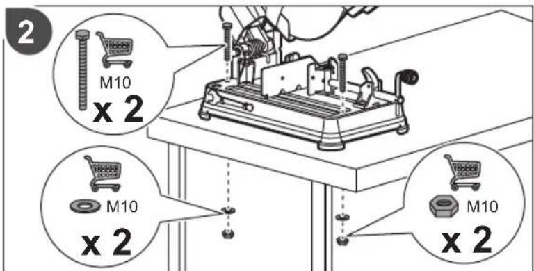
The product is intended to be fixed at the base to a solid bench top. If the base is not securely fixed machine may move during cutting operations, which increases the possibility of serious personal injury.
The product is to be used in dry conditions, with excellent ambient lighting and adequate ventilation.
The product is intended for consumer use and should only be used as described above and is not intended for any other purpose.
GENERAL POWER TOOL SAFETY WARNINGS
WARNING
Read all safety warnings, instructions, illustrations and specifications provided with this power tool. Failure to follow all instructions listed below may result in electric shock, fire and/or serious injury.
Save all warnings and instructions for future reference. The term "power tool" in the warnings refers to your mains-operated (corded) power tool or battery-operated (cordless) power tool.
WORK AREA SAFETY
- Keep work area clean and well lit. Cluttered or dark areas invite accidents.
- Do not operate power tools in explosive atmospheres, such as in the presence of flammable liquids, gases or dust. Power tools create sparks which may ignite the dust or fumes.
- Keep children and bystanders away while operating a power tool. Distractions can cause you to lose control.
ELECTRICAL SAFETY
■ Power tool plugs must match the outlet. Never modify the plug in any way. Do not use any adapter plugs with earthed (grounded) power tools. Unmodified plugs and matching outlets will reduce risk of electric shock.
- Avoid body contact with earthed or grounded surfaces, such as pipes, radiators, ranges and refrigerators. There is an increased risk of electric shock if your body is earthed or grounded.
■ Do not expose power tools to rain or wet conditions. Water entering a power tool will increase the risk of
electric shock.
- Do not abuse the cord. Never use the cord for carrying, pulling or unplugging the power tool. Keep cord away from heat, oil, sharp edges or moving parts. Damaged or entangled cords increase the risk of electric shock.
■ When operating a power tool outdoors, use an extension cord suitable for outdoor use. Use of a cord suitable for outdoor use reduces the risk of electric shock.
If operating a power tool in a damp location is unavoidable, use a residual current device (RCD) protected supply. Use of an RCD reduces the risk of electric shock.
PERSONAL SAFETY
■ Stay alert, watch what you are doing and use common sense when operating a power tool. Do not use a power tool while you are tired or under the influence of drugs, alcohol or medication. A moment of inattention while operating power tools may result in serious personal injury.
■ Use personal protective equipment. Always wear eye protection. Protective equipment such as a dust mask, non-skid safety shoes, hard hat, or hearing protection used for appropriate conditions will reduce personal injuries.
■ Prevent unintentional starting. Ensure the switch is in the off -position before connecting to power source and/or battery pack, picking up or carrying the tool. Carrying power tools with your finger on the switch or energising power tools that have the switch on invites accidents.
■ Remove any adjusting key or wrench before turning the power tool on. A wrench or a key left attached to a rotating part of the power tool may result in personal injury.
- Do not overreach. Keep proper footing and balance at all times. This enables better control of the power tool in unexpected situations.
■ Dress properly. Do not wear loose clothing or jewellery. Keep your hair and clothing away from moving parts. Loose clothes, jewellery or long hair can be caught in moving parts.
If devices are provided for the connection of dust extraction and collection facilities, ensure these are connected and properly used. Use of dust collection can reduce dust-related hazards.
- Do not let familiarity gained from frequent use of tools allow you to become complacent and ignore tool safety principles. A careless action can cause severe injury within a fraction of a second.
POWER TOOL USE AND CARE
- Do not force the power tool. Use the correct power tool for your application. The correct power tool will do the job better and safer at the rate for which it was
designed.
- Do not use the power tool if the switch does not turn it on and off. Any power tool that cannot be controlled with the switch is dangerous and must be repaired.
- Disconnect the plug from the power source and/or remove the battery pack, if detachable, from the power tool before making any adjustments, changing accessories, or storing power tools. Such preventive safety measures reduce the risk of starting the power tool accidentally.
■ Store idle power tools out of the reach of children and do not allow persons unfamiliar with the power tool or these instructions to operate the power tool. Power tools are dangerous in the hands of untrained users. - Maintain power tools and accessories. Check for misalignment or binding of moving parts, breakage of parts and any other condition that may affect the power tool's operation. If damaged, have the power tool repaired before use. Many accidents are caused by poorly maintained power tools.
- Keep cutting tools sharp and clean. Properly maintained cutting tools with sharp cutting edges are less likely to bind and are easier to control.
■ Use the power tool, accessories and tool bits etc. in accordance with these instructions, taking into account the working conditions and the work to be performed. Use of the power tool for operations different from those intended could result in a hazardous situation. - Keep handles and grasping surfaces dry, clean and free from oil and grease. Slippery handles and grasping surfaces do not allow for safe handling and control of the tool in unexpected situations.
SERVICE
- Have your power tool serviced by a qualified repair person using only identical replacement parts. This will ensure that the safety of the power tool is maintained.
CUT-OFF MACHINE SAFETY WARNINGS
■ Position yourself and bystander away from the plane of the rotating wheel. The guard helps to protect the operator from broken wheel fragments and accidental contact with wheel.
■ Use only bonded reinforced cut-off wheels for your power tool. Just because an accessory can be attached to your power tool, it does not assure safe operation.
■ The rated speed of the accessory must be at least equal to the maximum speed marked on the power tool. Accessories running faster than their rated speed can break and fly apart.
- Wheels must be used only for recommended applications. For example: do not grind with the side of a cut-off wheel. Abrasive cut-off wheels are
intended for peripheral grinding, side forces applied to these wheels may cause them to shatter.
■ Always use undamaged wheel flanges that are of correct diameter for your selected wheel. Proper wheel flanges support the wheel thus reducing the possibility of wheel breakage.
■ The outside diameter and the thickness of your accessory must be within the capacity rating of your power tool. Incorrectly sized accessories cannot be adequately guarded or controlled.
■ The arbour size of wheels and flanges must properly fit the spindle of the power tool. Wheels and flanges with arbour holes that do not match the mounting hardware of the power tool will run out of balance, vibrate excessively and may cause control.
- Do not use damaged wheels. Before each use, inspect the wheels for chips and cracks. If the power tool or wheel is dropped, inspect for damage or install an undamaged wheel. After inspecting and installing the wheel, position yourself and bystanders away from the plane of the rotating wheel and run the power tool at maximum no load speed for one minute. Damaged wheels will normally break apart during this test time.
■ Wear personal protective equipment. Depending on application, use face shield, safety goggles or safety glasses. As appropriate, wear dust mask, hearing protectors, gloves and shop apron capable of stopping small abrasive or workpiece fragments. The eye protection must be capable of stopping flying debris generated by various operations. The dust mask or respirator must be capable of filtrating particles generated by your operation. Prolonged exp high intensity noise may cause hearing loss.
- Keep bystanders a safe distance away from work area. Anyone entering the work area must wear personal protective equipment. Fragments of workpiece or of a broken wheel may fly away and cause injury beyond immediate area of operation.
■ Position the cord clear of the spinning accessory. If you lose control, the cord may be cut or snagged and your hand or arm may be pulled into the spinning wheel.
- Regularly clean the power tool's air vents. The motor's fan can draw the dust inside the housing and excessive accumulation of powdered metal may cause electrical hazards.
- Do not operate the power tool near flammable materials. Do not operate the power tool while placed on a combustible surface such as wood. Sparks could ignite these materials.
- Do not use accessories that require liquid coolants. Using water or other liquid coolants may result in electrocution or shock.
KICKBACK AND RELATED WARNINGS
Kickback is a sudden reaction to a pinched or snagged rotating wheel. Pinching or snagging causes rapid stalling
English
of the rotating wheel which in turn causes the uncontrolled cutting unit to be forced upwards toward the operator.
For example, if an abrasive wheel is snagged or pinched by the workpiece, the edge of the wheel that is entering into the pinch point can dig into the surface of the material causing the wheel to climb out or kick out. Abrasive wheels may also break under these conditions.
Kickback is the result of power tool misuse and/or incorrect operating procedures or conditions and can be avoided by taking proper precautions as given below.
- Maintain a firm grip on the power tool and position your body and arm to allow you to resist kickback forces. The operator can control upward kickback forces, if proper precautions are taken.
- Do not position your body in line with the rotating wheel. If kickback occurs, it will propel the cutting unit upwards toward the operator.
- Do not attach a saw chain, woodcarving blade, segmented diamond wheel with a peripheral gap greater than 10 mm or toothed saw blade. Such blades create frequent kickback and loss of control.
- Do not "jam" the wheel or apply excessive pressure. Do not attempt to make an excessive depth of cut. Overstressing the wheel increases the loading and susceptibility to twisting or binding of the wheel in the cut and the possibility of kickback or wheel breakage.
- When the wheel is binding or when interrupting a cut for any reason, switch off the power tool and hold the cutting unit motionless until the wheel comes to a complete stop. Never attempt to remove the wheel from the cut while the wheel is in motion otherwise kickback may occur. Investigate and take corrective action to eliminate the cause of wheel binding.
- Do not restart the cutting operation in the workpiece. Let the wheel reach full speed and carefully re-enter the cut. The wheel may bind, walk up or kickback if the power tool is restarted in the workpiece.
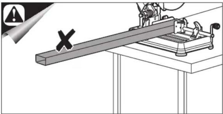
■ Support any oversized workpiece to minimize the risk of wheel pinching and kickback. Large workpieces tend to sag under their own weight. Supports must be placed under the workpiece near the line of cut and near the edge of the workpiece on both sides of the wheel.
ADDITIONAL SAFETY WARNINGS
■ Ensure that the product is always used on a stable and level surface.
■ Always use eye and ear protection when cutting.
■ Use personal protective equipment such as dust mask, gloves and apron.
If there is the risk of falling object, wear helmet or head protection.
■ Ensure that the abrasive cutting-off wheel is correctly fitted and tightened before use and run the machine at no-load for 30 s in a safe position, and to stop
immediately and replace the cutting-off wheel if there is considerable vibration.
■ Before making a cut, be sure all adjustments are secure.
■ Before performing any adjustment, make sure the tool is unplugged from the power supply. Failure to unplug cut-off machine could result in accidental starting causing possible serious personal injury.
■ Assemble all parts to your cut-off machine before connecting it to power supply.
■ Machine should never be connected to power supply when you are assembling parts, making adjustments, installing or removing wheels, or when not in use.
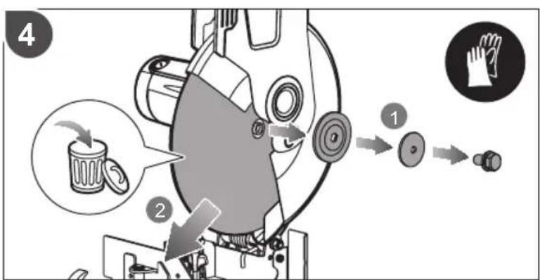
■ Visually inspect the abrasive wheel before every use. Check the wheel for fissures and cracks. Do not use damaged abrasive wheel.
■ Do not use saw blades.
■ Never use a wheel that is too thick to allow outer flange to engage with the flats on the spindle. Larger wheels will come in contact with the wheel guards, while thicker wheels will prevent the bolt from securing the wheel on the spindle. Either of these situations could result in a serious accident and can cause serious personal injury.
- Do not remove the machine's wheel guards. Never operate the machine with any guard or cover removed. Make sure all guards are operating properly before each use.
- Do not start your abrasive cut-off machine without checking for interference between the wheel and the machine base support. Damage may result to the wheel if it strikes the machine base support during operation of the machine.
- Do not attempt to cut wood or masonry with this cutoff machine. Never cut magnesium or magnesium alloy with this machine.
■ Do not tighten wheel excessively, since this can cause cracks.
■ Always ease the abrasive wheel against the work piece when starting to cut. A harsh impact can break the wheel.
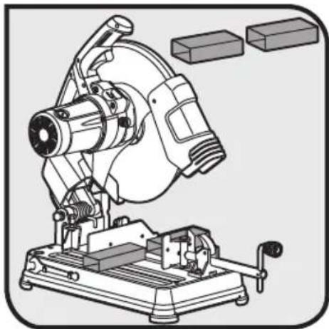
■ Never cut more than one work piece at a time. Do not stack more than one work piece on the machine base at a time.
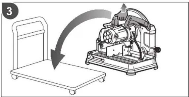
■ To minimize risk of tipping the machine, always support long work pieces.
■ Cutting steel will cause sparks. Do not operate in the presence of combustible or flammable materials.
■ Never leave tool running unattended. Do not leave tool until it comes to a complete stop. The wheel continues to rotate after the product is switched off.
■ Always release the power switch and allow the wheel to stop rotating before raising it out of the work piece.
- Keep hands away from cutting area. Keep hands away from wheel. Do not reach underneath work or around or under the wheel while the wheel is rotating. Do not attempt to remove cut material while wheel is moving.
■ Never stand or have any part of your body in line with
the path of the wheel.
■ Never stand on the tool. Serious injury could occur if the tool is tipped or if the wheel is unintentionally contacted.
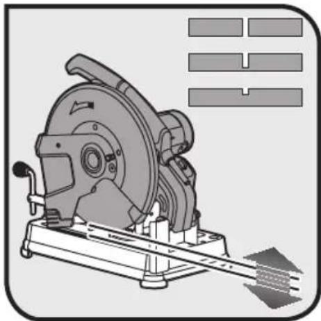
- Never perform any operation "freehand". Always secure the work piece to be cut in the vice. Refer to specification table for safe minimum size of work piece. Always ensure you grip at least 80 mm in the vice jaws to ensure security while grinding.
■ Never hand hold a work piece, it will become very hot while being cut.
A power spike causes voltage fluctuations and may affect other electrical products in the same power line. Connect the product to a power supply with an impedance equal to 0.233 Ω to minimize fluctuations. Contact your electric power supplier for further clarification.
It is recommended that the tool always be supplied via a residual current device having a rated residual current of 30mA or less.
RYOBI recommends that you use Metal cutting Disc COSB355A1 as a replacement whenever you need a new disc.
SAFETY WARNINGS FOR FITTING AN ABRASIVE WHEEL
To reduce the risk of injury, user must read and comply with instructions, warnings and operator's manual before starting to use this abrasive wheel. Failure to heed these warnings can result in wheel breakage and serious personal injury. Save these instructions.
■ The use of any wheel other than the one recommended in the machine instruction manual may present a risk of personal injury. Use only abrasive wheels which have marked speed equal or greater to that marked on the machine.
■ Never use abrasive wheel that is too thick to allow outer flange to engage with the flats on the spindle. Larger wheels will come in contact with the wheel guards, while thicker wheels will prevent the bolt from securing the wheel on the spindle. Either of these situations could result in a serious accident and can cause serious personal injury.
This abrasive wheel is for ferrous metal cutting only. Do not attempt to cut wood or masonry with it. Never cut magnesium or magnesium alloy with it.
This abrasive wheel is only suitable for dry cutting, should use it before the date of expiry (marking on label e.g. 11/2021).
■ Do not use damaged abrasive wheels, do not use wheels that are chipped, cracked or otherwise defective.
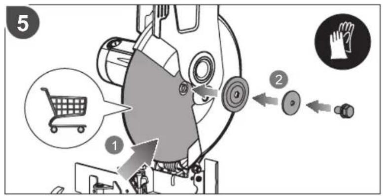
■ Ensure that the abrasive cutting-off wheel is correctly fitted and tightened before use.
■ The direction of rotation of the abrasive wheel is indicated on the tool, make sure the direction mark on
wheel consistent with the direction identified on the tool while installing and changing abrasive wheel.
■ Do not tighten abrasive wheel excessively, since this can cause cracks.
■ Machine should never be connected to power supply when you are installing or removing abrasive wheels.
■ Store your spare abrasive disc's carefully, they are easily damaged.
Information available on the abrasive wheel label
The information on the wheel label is IMPORTANT. Read and check it carefully to ensure you are selecting the correct type of disc.
1 Manufacturer, supplier, importer or trade mark
- Nominal dimensions of abrasive wheel, in particular the diameter of the bore
- Abrasive type, grain size, grade or hardness, type of bond and use of reinforcement e.g.
41A24RBF80
• 41--- abrasive type, flat cutting-off wheel
• A --- abrasive material: brown corundum
• 24 --- grain size
• R --- grade or hardness
• BF --- type of bond
• 80 --- maximum operating speed m/s
- Maximum operation speed in metres per second
- Maximum permissible speed of rotation in 1/min
- For declaration of conformity, the abrasive products shall be marked with EN 12413
- Restriction of use and safety warning symbols.
- Traceability code, eg. A production/batch number, expiry date or series number
RESIDUAL RISKS
Even when the product is used as prescribed, it is still impossible to completely eliminate certain residual risk factors. The following hazards may arise in use and the operator should pay special attention to avoid the following:
■ Stability. Ensure the tool is stable, if necessary secure it.
■ Inhalation of dust. Wear a mask if necessary.
■ Sparks and hot metal particles, these can cause fire, skin burns. Wear protective equipment during using.
■ Eye injury from metal particles. Wear eye protection when working.
■ Hearing injury – restrict exposure and wear appropriate hearing protection.
KNOW YOUR PRODUCT
See page 172.
- Handle, insulated gripping surface
- Trigger switch
- Top handle
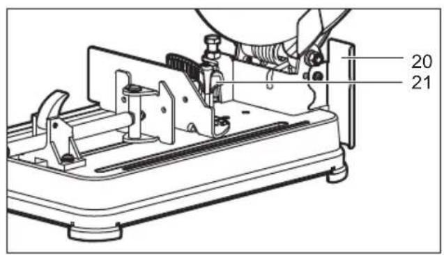
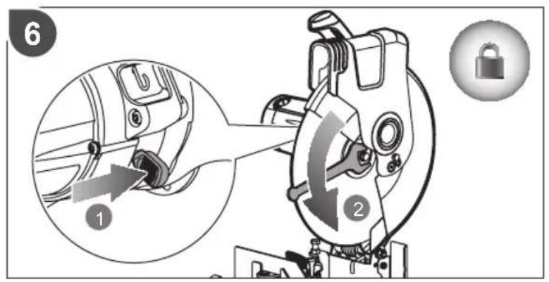
- Spindle lock
- Cutting depth adjustment screw
-
Cutting depth lock nut
-
Mitre guide
- Wrench
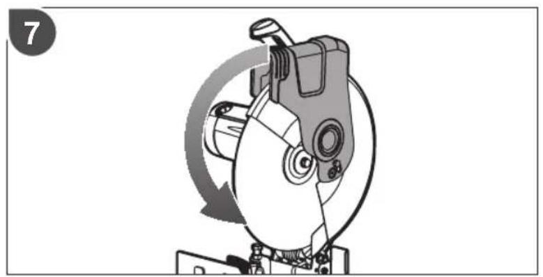
- Upper guard
- Lower guard
- Cutting wheel
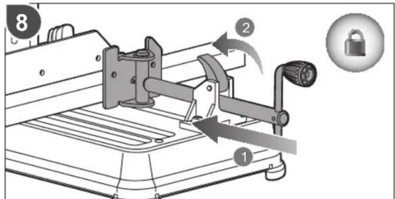
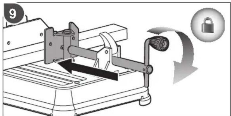
- Work clamp
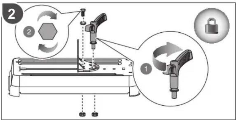
- Work clamp lock lever
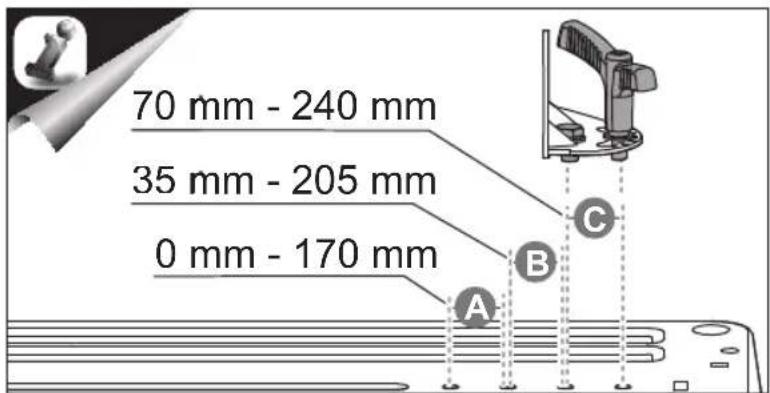
- Work clamp adjustment crank
- Rubber foot
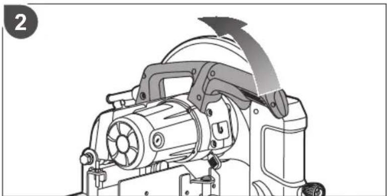
- Saw head lock chain
- Mounting hole
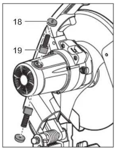
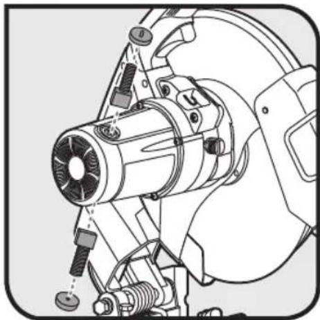
- Carbon brush cap
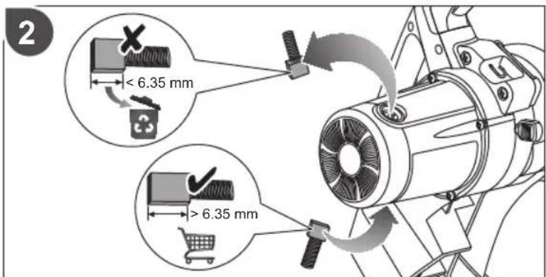
- Carbon brush
- Chip deflector
- Mitre guide lock lever
OPERATION TIPS
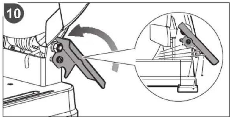
When the mitre guide is placed closest to the saw head pivot, the mitre guide lock lever may interfere with the head pivot when turning. Repeat the locking process by lifting and rewinding the lever until the mitre guide is tightly locked.
MAINTENANCE
- Do not modify the product in any way or use accessories not approved by the manufacturer. Your safety and that of others may be compromised.
- Do not use the product if any switches, guards or other functions does not work as intended. Return to an authorised service centre for professional repair or adjustment.
■ Do not make any adjustments while the motor is in motion.
■ Always make sure the machines plug has been removed from the mains power source before changing brushes, lubricating or when doing any works or maintenance on the machine.
■ After each use, check your machine for damage or broken parts and keep it in top working condition by repairing or replacing parts immediately.
■ Ensure that ventilation openings are kept clear, especially when working in dusty conditions. If it becomes necessary to clear dust, disconnect the product from the mains supply. Clean the openings using a soft brush.
■ Clean out accumulated dust.
■ To assure safety and reliability, all repairs with the exception of externally accessible brushes should performed by an authorised service centre.
If the power cord is damaged, it must be replaced by an authorised service center in order to avoid a hazard.
WARNING
For greater safety and reliability, all repairs should be performed by an authorised service centre.
ENVIRONMENTAL PROTECTION

Recycle raw materials instead of disposing of as waste. The machine, accessories and packaging should be sorted for environmental-friendly recycling.
SYMBOL

Safety alert

CE Conformity

EurAsian conformity mark

Ukrainian mark of conformity

Please read the instructions carefully before starting the product.

Class II tool, double insulation

Wear ear protection

Wear eye protection.

Not for wet grinding or cutting

Do not use chipped, cracked or defective grinding wheel

English

Wear safety gloves

Wear dust mask.

Do not expose to rain or use in damp locations.
Cutting-off wheel rotation direction (shown on wheel guard)

Waste electrical products should not be disposed of with household waste. Please recycle where facilities exist. Check with your Local Authority or retailer for recycling advice.
SYMBOLS IN THIS MANUAL

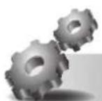
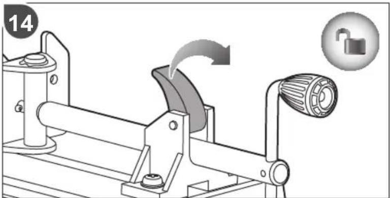
Lock

Unlock

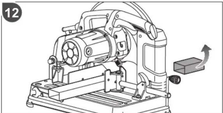
Waiting time for blade to reach full speed

Parts or accessories sold separately

Note

Warning
The following signal words and meanings are intended to explain the levels of risk associated with this product:
DANGER
Indicates an imminently hazardous situation, which, if not avoided, will result in death or serious injury.
WARNING
Indicates a potentially hazardous situation, which, if not avoided, could result in death or serious injury.
CAUTION
Indicates a potentially hazardous situation, which, if not avoided, may result in minor or moderate injury.
CAUTION
(Without Safety Alert Symbol) Indicates a situation that may result in property damage.
MACHEN SIE SICH MIT IHREM PRODUKT VERTRAUT
Siehe Seite 172.
STOP VEILIGHEIDSWAARSCHUWINGEN VOOR ZAGEN
EurAsian-symbol van overeenstemming.

SYMBOLER I MANUALLEN

Lås

Lås upp

SIKKERHET PÅ ARBEIDSOMRÅDET
No TC RU C-DE.AE61.B.06625
ÜLDISED OHUTUSREEGLID
HDIATUS
(Without Safety Alert Symbol) Indicates a situation that may result in property damage.
SIMBOLI U PRIRUČNIKU

Brava

Otključavanje

DODATNA VARNOSTNA OPOZORILA
OBOZNÁMTE SA S VAŠÍM PRODUKTOM
Vid' strana 172.

natural_image
Illustration of a mechanical device with a downward arrow and paper roll (no text or symbols)
natural_image
Mechanical device with rotating blade and cutting tool, no visible text or symbols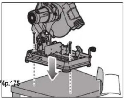
natural_image
Mechanical assembly diagram showing a robotic arm operating on a workbench with a downward arrow indicating motion (no text or symbols present)
natural_image
Mechanical device with upward arrow and page number 175, no visible text or symbols on the device itself
natural_image
Technical line drawing of a mechanical device with no visible text or symbols
natural_image
Technical line drawing of a mechanical assembly with no visible text or symbols
natural_image
Technical line drawing of a mechanical cutting tool with no visible text or symbols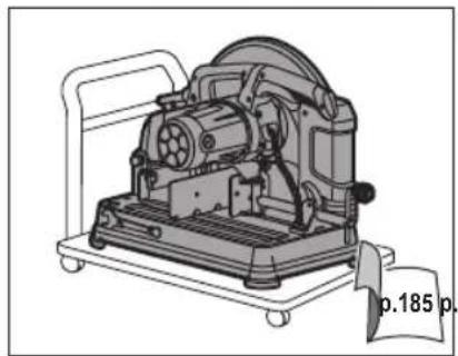
natural_image
Technical line drawing of a mechanical device with no visible text or symbols
natural_image
Illustration of a mechanical device with a cutting tool and paper roll, no text or symbols present
natural_image
Mechanical assembly diagram showing a clamping mechanism with no visible text or symbols
natural_image
Mechanical assembly diagram showing a presser pressing down on a workbench with a downward arrow indicating motion (no text or symbols present)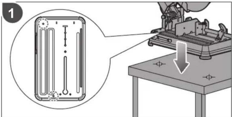
natural_image
Mechanical setup with a lever and clamping mechanism, no visible text or symbols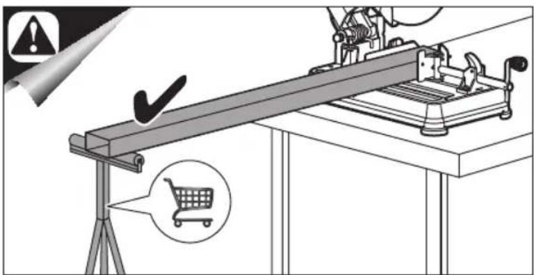
natural_image
Mechanical device with a downward arrow indicating compression or disassembly (no text or symbols visible)
natural_image
Mechanical assembly diagram showing a brake caliper and housing mechanism (no text or symbols)
natural_image
Mechanical device with upward arrow indicating motion or assembly (no text or symbols)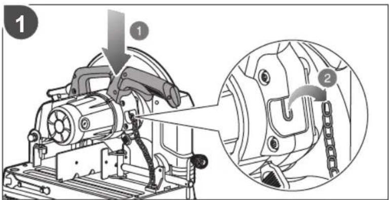
natural_image
Technical line drawing of a mechanical device with an arrow indicating motion or assembly (no text or symbols present)
natural_image
Illustration of a mechanical cutting machine with no visible text or symbols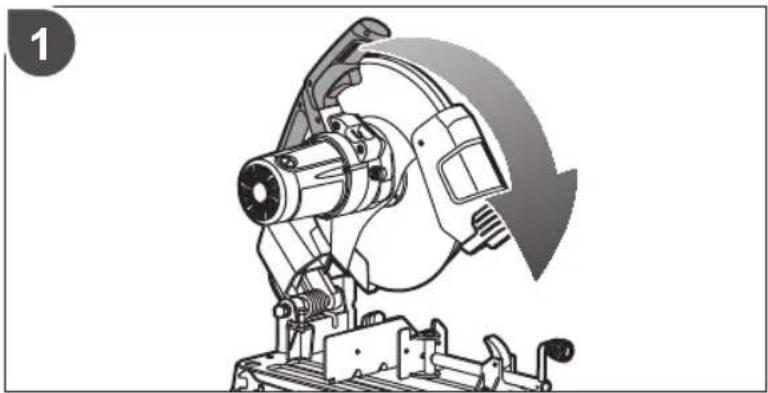
natural_image
Mechanical assembly diagram showing a brake caliper and housing mechanism (no text or symbols)
natural_image
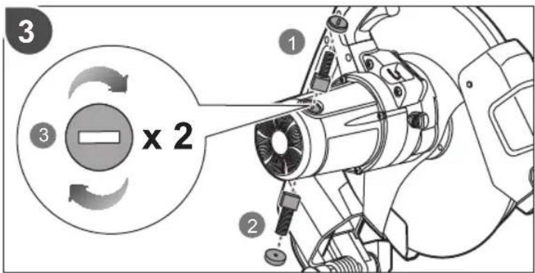
Three identical diagrams showing a mechanical component with hexagonal bolts, arranged in a V-shape, with no text or symbols present.
natural_image
Mechanical assembly diagram showing a bracket with springs and a mounted component (no text or symbols visible)

natural_image
Technical illustration of a mechanical cutting machine with a base and two rectangular blocks nearby (no text or symbols)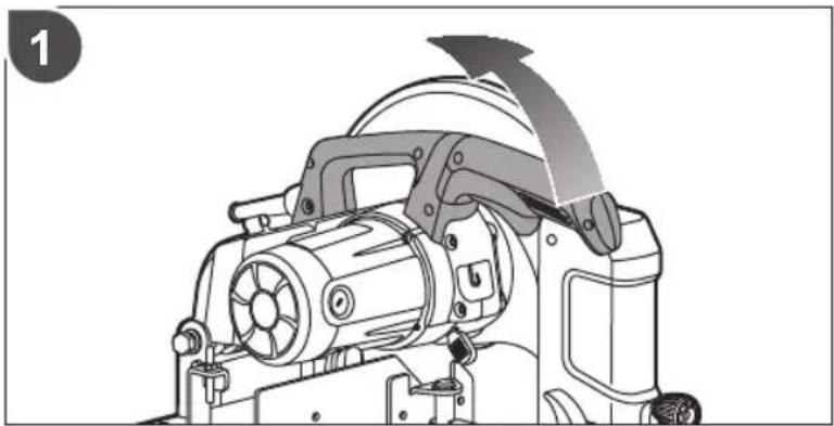
natural_image
Technical line drawing of a mechanical device with an arrow indicating motion or assembly (no text or symbols present)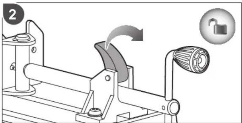
natural_image
Mechanical assembly diagram showing a lever mechanism with a rotating wheel and lock, accompanied by a lock icon (no text or symbols)
natural_image
Technical line drawing of a mechanical device with a lever and slide (no text or symbols)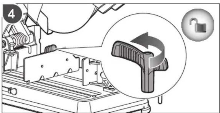
natural_image
Mechanical assembly diagram showing a lever mechanism with downward arrows indicating motion (no text or symbols present)

natural_image
Technical line drawing of a mechanical machine with a moving component and directional arrow (no text or symbols)
natural_image
Mechanical device diagram showing a lever mechanism with a lock and lock icon (no text or symbols)
natural_image
Technical line drawing of a mechanical device with a lever and slide assembly (no text or symbols)
natural_image
Illustration of a cutting machine with a blade and rotating components, showing an upward arrow indicating motion (no text or symbols present)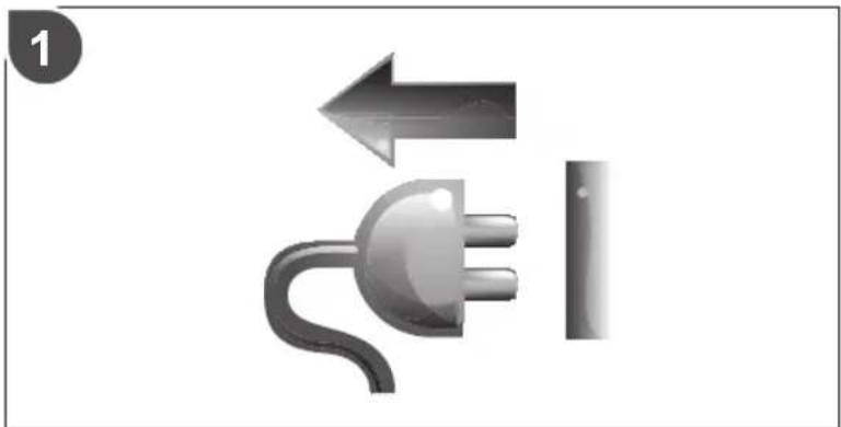
natural_image
Illustration of a plug and switch with directional arrows, no text or symbols present
natural_image
Mechanical assembly diagram showing a cutting tool and housing mechanism (no text or symbols)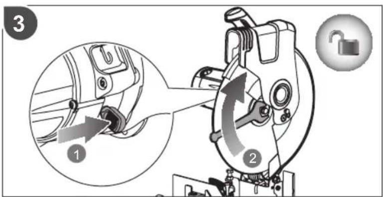
natural_image
Mechanical assembly diagram showing a rotating component with a curved arrow indicating rotation (no text or symbols)
natural_image
Technical line drawing of a mechanical assembly with no visible text or symbols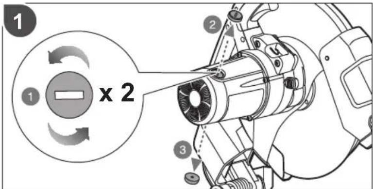
natural_image
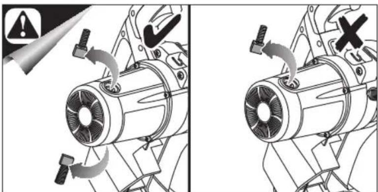
Mechanical assembly diagram showing two views of a motor with rotating blades and mounting hardware (no text or symbols)
natural_image
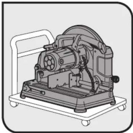
Technical illustration of a mechanical machine on a wheeled platform (no text or symbols visible)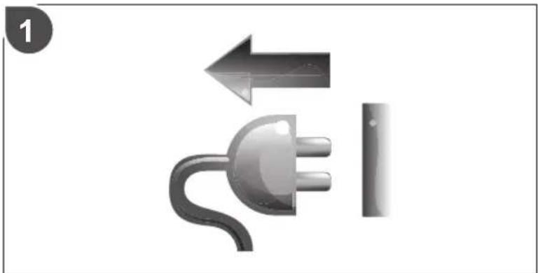
natural_image
Illustration of a plug and switch with directional arrows, no text or symbols present
English Français Deutsch Español Italiano Nederlands Português
| Product specifications | Caractéristiques de l'appareil | Produkt-Spezifikationen | Especificaciones del producto | Specifiche prodotto | Product specificaties | Especificações do produto |
| Cut-off Machine | Tronçonneuse | Trennschleifer | Máquina de corte | Macchina di taglio | Doorslijpmachine | |
| Model Modèle Modell Modelo | Modello Model Modelo | |||||
| Net weight | Poids net | Nettogewicht | Peso neto | Peso netto | Nettogewicht | |
| Wheel type (Type 41 reinforced abrasive wheel) | Type de disque (Disque abrasif renforcé de type 41) | Scheiben-Typ (Verstärkte Schleifscheibe Typ 41) | Tipo de disco (Disco abrasivo reforzado tipo 41) | Tipo di ruota (Ruota abrasiva rinforzata tipo 41) | Schijftype (Verstevigde slijpschijf type 41) | |
| Wheel diameter | Diamètre du disque | Durchmesser der Schleifscheibe | Diámetro de la muela | Diámetro della mola Schijfdi | diameter Diâmetro do disco | |
| Wheel thickness | Épaisseur du disque | Scheibenstärke | Grosor del disco | Spessore della ruota | Espessura do disco | |
| Arbor hole | Trou de broche | Mittelloch | Hueco del eje | Foro dell'albero | Orificio do eixo | |
| No-load speed | Vitesse à vide | Leerlaufdrehzahl | Velocidad sin carga | Velocità a vuoto | Onbelast toerental | |
| Input | Alimentation | Eingangsleistung | Cargador | Alimentazione | Input | Admissão |
| Power | Puissance | Leistung | Potencia | Alimentazione | Vermogen | Potência |
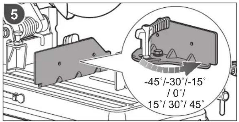
| Fence angle (Right / left) | Angle du guide (Droit / Gauche) | Anschlagwinkel (Rechts / Links) | Ángulo de valla (Derecha / Izquierda) | Angolo guida (Destro / Sinistro) | Aanslaghoek (Rechts / Links) | |
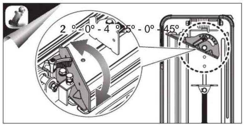
| Vice clamp angle (Right / left) | Angle de l'étau (Droit / Gauche ) | Winkel des Schraubspanners (Rechts / Links) | Ángulo de la abrazadera (Derecha / Izquierda) | Angolo morsetto (Destro / Sinistro) | Bankschroefhoek (Rechts / Links) | |
| Min. workpiece dimensions | Dimensions min. de la pièce | Min. Werkstückabmessungen | Dimensiones min. de la pieza de trabajo | Min. misurazione massima dei pezzi | Min. werkstukafmeting | |
| Measured values determined according to EN 62841 A-weighted sound pressure level | Valeurs mesurées obtenues selon EN 62841 Niveau de pression sonore pondéré-A | Gemäß EN 62841 gemessene Werte A-bewerteter Schalldruckpegel | Valores medidos determinados de acuerdo con EN 62841 Nivel de presión acústica ponderada en A | Valori misurati determinati in accordo con lo standard EN 62841 Livello di pressione sonora pesato A | Valores mesurées obtenues selon EN 62841 A-gewogen geluidsdrukniveau | |
| Uncertainty K | Incertitude K | Unsicherheit K | Incertidumbre K | Incertezza K | Onzekerheid K | |
| Measured values determined according to EN 62841 A-weighted sound power level | Valeurs mesurées obtenues selon EN 62841 Niveau de puissance sonore pondéré-A | Gemäß EN 62841 gemessene Werte A-bewerteter Schallleistungspegel | Valores medidos determinados de acuerdo con EN 62841 Nivel de potencia acústica ponderada en A | Valori misurati determinati in accordo con lo standard EN 62841 Livello di potenza sonora pesato A | Valores mesurées obtenues selon EN 62841 A-gewogen geluidsniveau | |
| Uncertainty K | Incertitude K | Unsicherheit K | Incertidumbre K | Incertezza K | Onzekerheid K | |
| Replacement parts: | Pièces de rechange: | Ersatzteile: | Piezas de repuesto: | Parti di ricambio: | Vervangonderdelen: | |
| Cutting wheel | Disque de coupe | Trennscheibe | Disco de corte | Ruota di taglio | Zaagwiel | |
| Carbon brush | Balai de charbon | Kohlebürste | La escobilla de carbón | Spazzola al carbonio | Koolborstel |
EN Maximum cutting capacity | FR Capacité maximale de coupe | DE Maximale Schnittleistung | ES Máxima capacidad de corte IT Capacità di taglio massima | NL Max. zaagcapaciteit | PT Capacidade de corte máxima | DA Max skærekapacitet SV Maximal sågkapacitet | FI Maksimileikkuusyvyys | NO Maksimum skjærekapasitet | RU Максимальная производительность резания PL Maksymalna zdolność cięcia | CS Maximální řezací kapacita | HU Maximális vágási teljesítmény | RO Capacitate maximă de täiere LV Maksimală griešanas jauda | LT Didžiausias pjovimo pajėgumas | ET Maksimaalne lõikevõime | HR Maksimalni kapacitet rezanja SL Največja rezalna kapaciteta | SK Maximálna kapacita rezania | BG Максimalen капацитет на рязане | UK Максимальна ріжуча здатність TR Maksimum kesme kapasitesi | EL Méγιστη δυνατότητα κοπής
| EN Cutting angle | FR Angle de coupe | DE Schneidwinkel | ES Ángulo de corteIT Angolo di taglio | NL Snijhoek PT Angulo de corte | DA SkaerevinkelSV Skärvinkel | FI Leikkuukulma | NO Kuttevinkel | RU Угол резанияPL Kąt cięcia | CS Úhel stříhání | HU Vágási szög RO Unghi de tăiereLV Griešanas lenkis | LT Pjovimo kampas | ET Lõikenurk | HR Kut rezanjaSL Rezalni kot | SK Uhol rezu | BG Ђгъл на рязане | UK Кут різанняTR Kesme açısı | EL Γωνία κοπής | 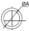 | 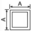 | 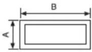 | 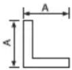 | |
 | 115 mm | 115 mm | 115 mm x 120 mm | 130 mm | |
 | 115 mm | 100 mm | 95 mm x 105 mm | 100 mm | |
| Dansk Svenska Suomi Norsk Русский Polski | ||||||
| Produktspecifikationer | Produktspecifikationer | Tuotteen tekniset tiedot | Produktspesifikasjoner | Характеристики изделия | Parametry techniczne | |
| Afskæringsmaskine=Skärmaskin=Katkaisukone=Kappemaskin=Отрезной станок=Przecinarka | ||||||
| Model Modell Malli=Modell Modель | Model ECO2335HG | |||||
| Nettovægt | Nettovikt | Kokonaispaino | Nettovekt | Вес нетто | Masa netto | 17,5 kg |
| Skivetype(Type 41 forstærket slibehjul) | Typ av klinga(Förstärkt slipande hjul av typ 41) | Laikan typpi(Tyypin 41 vahvistettu hiomapyörä) | Hjultype(Type 41 forsterket slipeskivo) | Тип абразивного круга(Абразивный круг, тип 41) | Typ ściemicy(Wzmacniana tarcza ściema typu 41) | |
| Slibeskivens diameter | Slipskivans diameter | Hiomalaikan halkaisija | Slipeskivens diameter | Диаметр колеса | Średnica tarczy | 355 mm |
| Hjultykkelse | Hjultjocklek | Pyörän paksuus | Skivetykkelse | Толщина круга | Grubość tarczy | 3,0 mm |
| Spindelhul | Spindelhål | Karan reikä | Spindelhull | Рабочее отверстие | Otwór trzpienia | 25,4 mm |
| Tomgangshastighed | Tomgångshastighet | Tyhjäkäyntinopeus | Hastighet ubelastet | Скорость на холостом ходу | Prędkość bez obciążenia | 4280 min^-1 |
| Strømforsyning | Matningsspänning | Virrankulutus | Input | Питание | Zasilanie | 220V - 240V ~ 50 Hz |
| Effekt | Ström | Teho | Effekt | Мощность | Moc | 2,300 W |
| Anslagsvinkel(Højre / venstre) | Anslagsvinkel(Höger / Vänster) | Ohjaimen kulma(Oikea / vasen) | Styreskinnevinkel(Høyre / Venstre) | Угол направляющей(Правый / Левый) | Kąt prowadnicy(W prawo / W lewo) | 45^ / 45^ |
| Skruestik-spændevinkel(Højre / venstre) | Vinkel för fästet på skruvstädet(Höger / Vänster) | Ruuvipenkin kulma(Oikea / vasen) | Tvingeklemmevinkel(Høyre / Venstre) | Угол зажима тисков(Правый / Левый) | Kąt zacisku imadla(W prawo / W lewo) | 45^ / 45^ |
| Max skærekapacitet | Maximal sågkapacitet | Maksimileikkuusyvyys | Maksimum skjærekapasitet | Максимальная производительность резания | Min. wymiary przedmiotu obrabianego |  115 mm (L) x 3 mm (W)x 3 mm (H) 115 mm (L) x 3 mm (W)x 3 mm (H) 115 mm (L) x 3 mm(ø) 115 mm (L) x 3 mm(ø) |
| Mälte værdier bestemmes i henhold til EN 62841A-væglet lydtryksniveau | Vården uppmätta enligtEN 62841A-vägd ljudtrycksnivå | Mitatut arvot määritetty EN 62841 -standardin mukaanA-painoteltu äänenpainelaso | Mälte verdier i samsvar med EN 62841A-vektet lydtrykknivå | Измеренные значения определены в соответствии с EN 62841Уровень А-взвешенного звукового давления | Zmierzone wartości określone wg EN 62841A-ważony poziom ciśnienia hałasu | L_PA = 91,5 dB(A) |
| Usikkerhed K | Osäkerhet K | Epätarkkuus K | Usikkerhet K | Разброс К | Niepewność pomiaru K | 3 dB(A) |
| Mälte værdier bestemmes i henhold til EN 62841A-vægtet lydeffektniveau | Vården uppmätta enligtEN 62841A-vägd ljudeffektsnivå | Mitatut arvot määritetty EN 62841 -standardin mukaanA-painoteltu äänenteho | Mälte verdier i samsvar med EN 62841A-vektet lydeffektnivå | Измеренные значения определены в соответствии с EN 62841Уровень А-взвешенной звуковой мощности | Zmierzone wartości określone wg EN 62841A-ważony poziom natężenia hałasu | L_PA = 104,5 dB(A) |
| Usikkerhed K | Osäkerhet K | Epätarkkuus K | Usikkerhet K | Разброс К | Niepewność pomiaru K | 3 dB(A) |
| Reservedele: | Utbytesdelar: | Varaosat: | Reservedeler: | Запасные части: | Części zamienne: | |
| Skårehjul | Skärklinga | Leikkuterä | Skjæreblad | Отрезной диск | Tarcza tnąca | COSB355A1 |
| Kulbørste | Kolborste | Hilihnaja | Karbonbørste | Угольная щетка | Uhlikovy kartáček | 5131031610 |
115 mm (L) x 3 mm (W)
x 3 mm (H)
115 mm (L) x 3 mm(ø)
L_pA = 91,5 ~dB(A)
L_Na = 104.5 dB(A)
| Čeština | Magyar | Română | Latviski | Lietuviškai | Eesti |
| Technické údaje produktu | Termék müszaki adatai | Specificațiile produsului | Produkta specifikácijas | Gaminio techninės savybės | Toote tehnilised andmed |
| Zkracovací pila na kovy | Darabológép | Mașină de debitat | Metăla griešanas iekārta | Diskinės metalo pjovimo staklės | Metallilõikur |
| Model Tipus Model Modelis Modelis | Mudeli tähis | ||||
| Čistă hmotnost | Nettö tömeg | Greutate netă | Svars neto | Neto svoris | Netomass |
| Typ kotouče(Vyztužený brusný kotouč, typ 41) | Tárcsa tipusa(41-es tipusú erősített darabolökerék) | Tip disc(Disc abraziv ranforsat tip 41 ) | Ripas tips(41. tipa armetă abrazivă ripa) | Disko tipas(41 tipo sustiprintas šlifavimo diskas) | Lõikeketta tüüp(Tüüp 41 tugevdatud lihvimisketas) |
| Průměr brusného kotouče | Korong átmérője | Diametrul polizorului | Diska diamets | Disko skersmuo | Ketta läbimõöt |
| Tloušťka kotouče | Kerék vastagsága | Grosime disc | Abrazivās ripas biezums | Disko storis | Ketta paksus |
| Otvor hřidele | Tengelyfurat | Orificiu arbore | Vârpstas atvere | Ašies anga | Võlllava |
| Otáčky naprázdno | Üresjáratí fordulatszám | Viteză în gol | Apgriezieni bez slodzes | Greitis be apkrovimo | Kilrus ilma koormuseta |
| Vstup | Bemenet | Intrare | leeja | Ivestis | Vooluvõrk |
| Výkon | Teljesítmény | Alimentare | Străva | Galia | Võimsus |
| Ühel dorazu(Pravý / levý) | Vezetősín szöge(Jobbra / Balra) | Unghi riglă de ghidaj(Dreapta / Stânga) | Barjeras lenjis(Pa labi / pa kreisi) | Užthvaros kampas(Dešinė / kairė) | Alustoe nurk(Parem / Vasak) |
| Ühel ruční svěrky(Pravý / levý) | Satuba fogås szöge(Jobbra / Balra) | Unghi mecanism de fixare menghină(Dreapta / Stânga) | Skrůvspíju spaľu lenjis(Pa labi / pa kreisi) | Spaustuvo kampas(Dešinė / kairė) | Pítskruvi nurk(Parem / Vasak) |
| Min. rozměry obrobku | Min. munkadarab méretek | Dimensiunile minimă ale piesei de prelucrat | Min. . apstrădăjamās detaļas izměrs | Min. apdorojamos detalės matmenys | Min. tooriku mõõtmed |
| Naměřené hodnoty zjištěné dle EN 62841Hladina akustického tlaku vážoná funkci A | A mért értékek meghatározása az EN 62841 szerint történtA-súlyozott hangnyomásszint | Valori măsurate determinate în conformitate cu EN 62841Nivel de presiune acustică ponderată A | Izměrīlās vērtības saskaņa ar EN 62841A-līmeņa skaņas spiediena Ilmenis | Išmatuotosios vertės nustatytos pagal EN 62841A svertinis garso slėgio lygis | Mõõteväärtused on kindlaks määratud vastavait standardile EN 62841A-kaalutud helirõhu tase |
| Nejistota K | Bizonytalanság K | Incertitudine K | Kļūdas vērtība K | Nepastovumas K | Mõõtemääramatus K |
| Naměřené hodnoty zjištěné dle EN 62841Hladina akustického výkonu vážoná funkci A | A mért értékek meghatározása az EN 62841 szerint történtA-súlyozott hangteljesítményszint | Valori măsurate determinate în conformitate cu EN 62841Nivel de putere acustică ponderată A | Izměrītās vērtības saskaņa ar EN 62841A-līmeņa skaņas jaudas Ilmenis | Išmatuotosios vertės nustatytos pagal EN 62841A svertinis garso galios lygis | Mõõteväärtused on kindlaks määratud vastavait standardile EN 62841A-kaalutud helivõimsuse tase |
| Nejistota K | Bizonytalanság K | Incertitudine K | Kļūdas vērtība K | Nepastovumas K | Mõõtemääramatus K |
| Náhradní díly: | Cserealkatrészek: | Piese de schimb: | Rezerves daļas: | Atsarginės detalės: | Asendusosad: |
| Řezný kotouč | Vågótárcsa | Disc de tāiere | Zăgripa | Pjovimo diskas | Lõikeketas |
| Uhlikový kartáček | Szénkefe | Perie de carbon | Ogles suka | Anglinis šepetys | Süsiharjad |


The declared noise emission value(s) have been measured in accordance with a standard test method of EN 62841-1 and EN 62841-3-10, and may be used for comparing one tool with another.
The declared noise emission value(s) may also be used in a preliminary assessment of exposure.
The noise emissions during actual use of the power tool can differ from the declared values depending on the ways in which the tool is used especially what kind of workpiece is processed.
Identify safety measures to protect the operator that are based on an estimation of exposure in the actual conditions of use (taking account of all parts of the operating cycle such as the times when the tool is switched off and when it is running idle in addition to the trigger time).
Wear ear protectors. Exposure to noise can cause hearing loss.

AVERTISSEMENT
In addition to any statutory rights resulting from the purchase, this product is covered by a warranty as stated below.
- The warranty period is 24 months for consumers and commences on the date the product was purchased. This date has to be documented by an invoice or other proof of purchase. The product is designed and dedicated to consumer and private use only. So there is no warranty provided in case of professional or commercial use. This warranty applies only on new products.
- There is a possibility to extend for a part of the range (AC/DC) the warranty period over the period described above using the registration on the www.ryobitools.eu website. The eligibility of products for extended warranty is clearly displayed in stores and / or on packaging and is contained within the product documentation. The end user is required to register his/her newly-acquired products online within 30 days from the date of purchase. The end user may register for the extended warranty in his/her country of residence if listed on the online registration form where this option is valid. Furthermore, end users must give their consent to the storage of their personal data that is required to be entered online. They must also accept the terms and conditions. The registration confirmation receipt, which is sent out by e-mail, and the original invoice showing the date of purchase will serve as proof of the extended warranty.
- The warranty covers all defects of the product during the warranty period due to faults in workmanship or material at the purchase warranty is limited to repair and/or replacement and does not include any other obligations including but not limited to incidental or consequential damages. The warranty is not valid if the product has been misused, used contrary to the instruction manual, or has been incorrectly connected to a power supply. This warranty does not apply to:
— any damage to the product that is the result of improper or lack of maintenance
-any product that has been altered or modified
– any product where original identification (trade mark, serial number) markings have been defaced, altered or removed
– any damage caused by non-observance of the instruction manual
– any product not displaying the CE approval mark on the rating plate
– any product that has been attempted to be repaired by a non-authorised warranty service centre or without prior authorisation by Techtronic Industries
– any product connected to improper power supply (amps, frequency)
– any damage caused by external influences (water, chemical, physical, shocks) or foreign substances
– normal wear and tear spare parts
– inappropriate use, overloading of the tool
- use of non-approved accessories or parts
- Power tool accessories provided with the tool or purchased separately, including but not limited to screw driver bits, drill bits, abrasive discs, sand paper and blades, lateral guide, etc.
- Components (parts and accessories) subject to natural tear, including but not limited to service & maintenance kits, carbon brushes, bearings, chuck, SDS drill bit attachment or reception, power cord, auxiliary handle, transport carry case, sanding plate, dust bag, dust exhaust tube, felt washers, impact wrench pins & springs, etc.
- For servicing, the product must be sent or presented to a RYOBI authorised service station listed for each country in the following list of service station addresses. In some countries your local RYOBI dealer undertakes to send the product to the RYOBI service organisation. When sending a product to a RYOBI service station, the product should be safely packed without any dangerous contents such as petrol, marked with sender's address and accompanied by a short description of the fault.
- A repair / replacement under this warranty is free of charge. It does not constitute an extension or a new start of the warranty period. Exchanged parts or products become our property. In some countries delivery charges or postage will have to be paid by the sender. Your statutory rights arising from the purchase of the product remain unaffected
- This warranty is valid in the European Community, Switzerland, Iceland, Norway, Liechtenstein, Turkey and Russia. Outside these areas, please 6. contact your authorised RYOBI dealer to determine if another applies.
AUTHORISED SERVICE CENTRE
To find an authorised service centre near you, visit http://uk.rycheader/service-and-support/service-agents
FR RYOBI® CONDITIONS D'APPLICATION DE LA GARANTIE
DECLARATION OF CONFORMITY
Techtronic Industries GmbH
Max-Eyth-Straße 10, 71364 Winnenden, Germany
Herewith we declare that the product
Cut-off machine
Brand: RYOBI
Model number: ECO2335HG
Serial number range: 46299301000001 - 46299301999999
is in conformity with the following European Directives and harmonised standards
2006/42/EC, 2014/30/EU, 2011/65/EU
EN 55014-1:2017; EN 55014-2:2015;
EN 61000-3-2:2014; EN 61000-3-11:2000;
EN 62841-1:2015; EN 62841-3-10:2015; EN 50581:2012
CE
Todd Chipner
Sr. Director, Regulatory & Safety
Authorised to compile the technical file:
Alexander Krug, Managing Director
Techtronic Industries GmbH
Max-Eyth-Straße 10, 71364 Winnenden, Germany

DÉCLARATION DE CONFORMITÉ
Techtronic Industries GmbH
Max-Eyth-Straße 10, 71364 Winnenden, Germany
Max-Eyth-Straße 10, 71364 Winnenden, Germany

Max-Eyth-Straße 10, 71364 Winnenden, Germany
Max-Eyth-Straße 10, 71364 Winnenden, Germany

Max-Eyth-Straße 10, 71364 Winnenden, Germany
Max-Eyth-Straße 10, 71364 Winnenden, Germany

Max-Eyth-Straße 10, 71364 Winnenden, Germany
Max-Eyth-Straße 10, 71364 Winnenden, Germany

CONFORMITEITSVERKLARING
Techtronic Industries GmbH
Max-Eyth-Straße 10, 71364 Winnenden, Germany
Max-Eyth-Straße 10, 71364 Winnenden, Germany


Max-Eyth-Straße 10, 71364 Winnenden, Germany
Max-Eyth-Straße 10, 71364 Winnenden, Germany

SÄÄNNÖSTEN NOUDATTAMINEN
Techtronic Industries GmbH
Max-Eyth-Straße 10, 71364 Winnenden, Germany
Max-Eyth-Straße 10, 71364 Winnenden, Germany

OVERENSSTEMMELSESERKLAERING
Techtronic Industries GmbH
Max-Eyth-Straße 10, 71364 Winnenden, Germany
Vi erklærer hermed, at produktet
Afskæringsmaskine
Brand: RYOBI
Modelnummer: ECO2335HG
Max-Eyth-Straße 10, 71364 Winnenden, Germany

SAMSVARSERKLÆRING
Techtronic Industries GmbH
Max-Eyth-Straße 10, 71364 Winnenden, Germany
Max-Eyth-Straße 10, 71364 Winnenden, Germany

KONFORMITETSDEKLARATION
Techtronic Industries GmbH
Max-Eyth-Straße 10, 71364 Winnenden, Germany
Max-Eyth-Straße 10, 71364 Winnenden, Germany

Max-Eyth-Straße 10, 71364 Winnenden, Germany
Max-Eyth-Straße 10, 71364 Winnenden, Germany


DEKLARACJA ZGODNOŚCI
Techtronic Industries GmbH
Max-Eyth-Straße 10, 71364 Winnenden, Germany
Max-Eyth-Straße 10, 71364 Winnenden, Germany

DECLARATIE DE CONFORMITATE
Techtronic Industries GmbH
Max-Eyth-Straße 10, 71364 Winnenden, Germany
Alexander Krug, Director General
Techtronic Industries GmbH
Max-Eyth-Straße 10, 71364 Winnenden, Germany

PROHLÁŠENÍ O SHODĚ
Techtronic Industries GmbH
Max-Eyth-Straße 10, 71364 Winnenden, Germany
Max-Eyth-Straße 10, 71364 Winnenden, Germany

ATBILSTĪBAS DEKLARĀCIJA
Techtronic Industries GmbH
Max-Eyth-Straße 10, 71364 Winnenden, Germany
Max-Eyth-Straße 10, 71364 Winnenden, Germany

MEGFELELŐSÉGI NYILATKOZAT
Techtronic Industries GmbH
Max-Eyth-Straße 10, 71364 Winnenden, Germany
Max-Eyth-Straße 10, 71364 Winnenden, Germany

ATITIKTIES PAREIŠKIMAS
Techtronic Industries GmbH
Max-Eyth-Straße 10, 71364 Winnenden, Germany
Max-Eyth-Straße 10, 71364 Winnenden, Germany


VASTAVUSDEKLARATSIOON
Techtronic Industries GmbH
Max-Eyth-Straße 10, 71364 Winnenden, Germany
Kinnitame, et see toode
Metallilõikur
Mark: RYOBI
Mudeli number: ECO2335HG
Seerianumbri vahemik: 46299301000001 - 46299301999999
Max-Eyth-Straße 10, 71364 Winnenden, Germany

IZJAVA O USKLAĐENOSTI
Techtronic Industries GmbH
Max-Eyth-Straße 10, 71364 Winnenden, Germany
Max-Eyth-Straße 10, 71364 Winnenden, Germany

IZJAVA O SKLADNOSTI
Techtronic Industries GmbH
Max-Eyth-Straße 10, 71364 Winnenden, Germany
Max-Eyth-Straße 10, 71364 Winnenden, Germany

PREHLÁSENIE O ZHODE
Techtronic Industries GmbH
Max-Eyth-Straße 10, 71364 Winnenden, Germany
Max-Eyth-Straße 10, 71364 Winnenden, Germany

Max-Eyth-Straße 10, 71364 Winnenden, Germany
Max-Eyth-Straße 10, 71364 Winnenden, Germany

Max-Eyth-Straße 10, 71364 Winnenden, Germany
Max-Eyth-Straße 10, 71364 Winnenden, Germany


UYGUNLUK BEYANI
Techtronic Industries GmbH
Max-Eyth-Straße 10, 71364 Winnenden, Germany
Max-Eyth-Straße 10, 71364 Winnenden, Germany

ΔΗΛΩΣΗ ΣΥΜΜΟΡΦΩΣΗΣ
Techtronic Industries GmbH
Max-Eyth-Straße 10, 71364 Winnenden, Germany
Max-Eyth-Straße 10, 71364 Winnenden, Germany


EN RYOBI is a trade mark of Ryobi Limited, and is used under license.
© 2012-20 Techtronic Cordless GP.
© 2012-20 Techtronic Cordless GP.
© 2012-20 Techtronic Cordless GP.
© 2012-20 Techtronic Cordless GP.
© 2012-20 Techtronic Cordless GP.
© 2012-20 Techtronic Cordless GP.
© 2012-20 Techtronic Cordless GP.
© 2012-20 Techtronic Cordless GP.
© 2012-20 Techtronic Cordless GP.
© 2012-20 Techtronic Cordless GP.
© 2012-20 Techtronic Cordless GP.
© 2012-20 Techtronic Cordless GP.
© 2012-20 Techtronic Cordless GP.
© 2012-20 Techtronic Cordless GP.
© 2012-20 Techtronic Cordless GP.
© 2012-20 Techtronic Cordless GP.
© 2012-20 Techtronic Cordless GP.
© 2012-20 Techtronic Cordless GP.
© 2012-20 Techtronic Cordless GP.
HR RYOBI je žig tvrtke Ryobi Limited i koristi se po licenci.
© 2012-20 Techtronic Cordless GP.
© 2012-20 Techtronic Cordless GP.
© 2012-20 Techtronic Cordless GP.
© 2012-20 Techtronic Cordless GP.
© 2012-20 Techtronic Cordless GP.
© 2012-20 Techtronic Cordless GP.
© 2012-20 Techtronic Cordless GP.


RYOBI®
Techtronic Industries GmbH
Max-Eyth-Straße 10,
71364 Winnenden, Germany
20200217v10