
HG Roof Two - Welding machine STEINEL - Free user manual and instructions
Find the device manual for free HG Roof Two STEINEL in PDF.

| Product type | Automatic welding machine for roofing |
| Brand | Steinel |
| Model | HG Roof Two |
| Dimensions (H x W x D) | 351 x 433 x 358 mm (with gun folded) |
| Weight | Approximately 14 kg + 3 additional weights of 1.1 kg each |
| Power supply | 220-240 V ~, 50/60 Hz |
| Power | Approximately 2000 W max. |
| Temperature range | 50 °C to 620 °C (digital adjustment with display) |
| Air flow | Adjustable from 30 to 100% |
| Travel speed | 1.5 to 5 m/min |
| Protection class | I |
| Sound pressure level | ≤ 70 dB(A) |
| Total vibration | ≤ 2.5 m/s² / K = 0.08 m/s² |
| Main functions | Overlap welding of roofing membranes on flat roofs; temperature and air flow adjustment; 4 preset programs; memory function; cooling mode; residual heat indicator |
| Maintenance and cleaning | Clean the welding nozzle with a wire brush; microparticle filter cleanable with compressed air |
| Safety | Thermal protection; residual heat indicator; anti-drop device; automatic shut-off in cooling mode |
| Spare parts and repairability | Straight hot air gun replaceable without opening the housing; replaceable heating element; interchangeable welding nozzle |
| Warranty | 12 months or 10,000 hours of use |
| Included accessories | Telescopic handle, pressure roller, side clamp, spacer wheel, additional weights |
Frequently Asked Questions - HG Roof Two STEINEL
User questions about HG Roof Two STEINEL
0 question about this device. Answer the ones you know or ask your own.
Ask a new question about this device
Download the instructions for your Welding machine in PDF format for free! Find your manual HG Roof Two - STEINEL and take your electronic device back in hand. On this page are published all the documents necessary for the use of your device. HG Roof Two by STEINEL.
USER MANUAL HG Roof Two STEINEL
natural_image
World map silhouette in grayscale, showing continents and oceans without any text or labelsContact www.steinel.de/contact

100/30/0 12/2019_A Technische Änderungen vorzestern. / Subject to technical modification without notice.
GB Translation of the original operating instructions
Please familiarise yourself with these operating instructions before using this product, because prolonged reliable and trouble-free operation will only be ensured if it is handled properly. We hope your automatic hot air welding machine will give you lasting satisfaction.

Safety precautions
Read and observe this information before using the tool. Failure to observe the operating instructions may result in the tool becoming a source of danger.
When using electric power tools, observe the following basic safety precautions to avoid electric shock as well as the risk of injury and fire. Used carelessly, the tool can start an unintentional fire or injure persons. Check the machine for any damage (power cord, housing etc.) before putting it into operation and do not use the machine if it is damaged. Do not leave the tool switched on unattended. Children should be supervised to make sure they do not play with the tool.
About this document
Please read carefully and keep in a safe place. - Under copyright. Reproduction either in whole or in part only with our consent. - Subject to change in the interest of technical progress.
First time of use
A small quantity of smoke may develop when the tool is used for the first time. This smoke is caused by binding agents released from the heater's insulating film during the first time of use.
To let the smoke escape quickly, the tool should not be turned inwards. The area you are working in should be well ventilated when using the tool for the first time.
Any smoke coming out of the tool is not harmful!
Take the ambient conditions into account.
Do not expose electric power tools to rain. Do not use electric power tools when they are damp or in a damp or wet environment. Exercise care when using the tool in the proximity of flammable materials. Do not direct the tool at one and the same place for a prolonged period. Do not use in the presence of an explosive atmosphere. Heat emitted may be conducted to flammable materials that are hidden from direct sight.

Safety precautions
Protect yourself from electric shock.
Avoid coming into contact with earthed objects, such as pipes, radiators, cookers or refrigerators. Do not leave the tool unattended while it is in operation.
Store your tools in a safe place.
After use, set the tool down and let it cool before putting it away. When not in use, tools must be stored in a dry, locked room out of children's reach. This tool may be used by children aged 8 or above and by persons with reduced physical, sensory or mental capabilities or lack of experience and knowledge if they are supervised or have been given instructions on how to use the tool safely and understand the hazards involved.
Use by children is not recommended.
Do not allow children to play with the tool.
Children are not allowed to clean or carry out maintenance work on the tool without supervision.

Do not overload your tools.
Your work results and safety will be enhanced if you operate the tool within the specified output range. Do not carry the tool by the power cord. Do not unplug the tool by pulling on the power cord. Protect the power cord from heat, oil and sharp edges.

Risk of falling
In areas involving the risk of falling, use fall protection. For welding work on a roof parapet (fascias, eaves) the automatic welding machine must be attached to a securing fixture with horizontal guides (e.g. rail or cable securing system) by the carrying handle (B) to prevent it from falling.


Beware of toxic gases and fire hazards.
Toxic gases may develop when working on plastics, paints, varnishes or similar materials. Beware of fire and ignition hazards. For your own safety, only use accessories and attachments that are specified in the operating instructions or recommended or specified by the tool manufacturer. Using attachments or accessories other than those recommended in the operating instructions or catalogue may result in personal injury.


Safety precautions
Operation only under supervision.
Constantly watch the tool while it is in operation. Heat coming from the tool can set alight combustible materials in its proximity. The tool must only be used by trained specialists or under their supervision.
Personal protection
While working with the machine, wear your personal protection gear (e.g. protective gloves, work shoes etc.)
Repairs by a qualified electrician only
This electric power tool complies with the relevant safety regulations. Repairs should only be performed by a qualified electrician. Otherwise the user may run the risk of accidents.
Damage to the mains power cord.
If this tool's main power cord is damaged, it must be replaced by the manufacturer or its customer service department or a similarly qualified person so as to avoid hazards.
Residual heat indicator
The residual heat indicator serves as a visual warning to prevent injury from direct skin contact with the hot nozzle outlet. The residual heat indicator also works when the tool is unplugged. The indicator starts working after the

tool has been in use for 90 seconds and keeps flashing until the temperature at the nozzle outlet has fallen below 60°C at room temperature. The residual heat indicator does not show if the tool has been in operation for less than 90 seconds. Responsibility always rests with the user as care must be taken at all times when handling hot air tools.
Keep these safety precautions with the tool.

For your safety
The tool is protected from overheating:
The thermal cut-out completely shuts down the tool if it is overloaded.
Tool description - operation
Please note: always try out the airflow and temperature on a test piece first! Take care when changing hot nozzles! When using the automatic hot air welding machine, make sure that the base surface is clean. Switching ON causes brief voltage drops. If the mains power supply system is not absolutely stable, other equipment may be affected. No malfunctions are likely to occur with mains impedances of less than 0.35 ohms.
Proper use
Electric power tool for overlap welding roof membranes on flat roofs Only use genuine STEINEL replacement parts and accessories as you will otherwise not be able to make any warranty or guarantee claims.
Getting started
Power cord and extension cable
- The mains voltage must match the rated voltage (→Technical specifications) specified on the tool.
- The mains power cord must be able to move freely and hinder neither user nor third parties in their work (risk of tripping over).
- Extension cables must be approved for the place of use and marked accordingly. Take into account any minimum cross section needed for the extension cable.
We recommend extension cables with a cable cross-section of 2.5 mm ^2 and a maximum length of 50 m. Restrictions to maximum temperature must be expected if cables of other sizes are used.
- Hook the mains power cord into the eye on the telescopic handle to avoid running the machine over the cable.
Positioning the tool
- Make sure that the material being welded is clean between the upper and lower surface of the overlap.
• Then make sure that welding nozzle
pressure roller and downholder are clean.
- Move the hot air tool into parked position.
- Now raise the automatic hot air welding machine by means of the telescopic handle and move the tool to the welding position.
- Now position the root membrane and then lower the downholder.
Starting the tool
- Once you have prepared the work area and the automatic hot air welding machine, connect the automatic hot air welding machine to the mains power supply.
- Switch the automatic hot air welding machine ON via the "mains ON/OFF switch".
- Switch ON the barrel-type hot air tool.
- Set airflow rate and temperature.
- Machine heats up to the selected settings.
Welding process
Preparing to weld
- As soon as you have switched on the heating element, you will see a dynamic display of the current air temperature.
- Make sure the welding temperature is reached before you start to work (the tool takes 3 to 5 minutes to heal up).
- Now make test welds in accordance with the welding instructions of the material manufacturer and/or national standards or guidelines, and check the results. Adjust the welding data if necessary.
Starting to weld
- Turn the hot air tool inwards and insert the welding nozzle in between the overlapping membranes as far as it will go.
- The automatic welding machine immediately sets off (automatic start-up system).
Guiding the machine during the welding process
- Guide the automatic hot air welding machine by the telescopic handle along the overlap, always paying attention to the position of the downholder.
- Avoid pressing on the telescopic handle during the welding process as this may result in welding flaws.
Finishing welding
- Turn the hot air tool outwards. The automatic welding machine stops immediately.
Switching OFF machine
- On the hot air tool, switch the heating element OFF so that the welding nozzle can cool down.
Note: press ON/OFF for several seconds and the machine will go into cooling mode. Cold air is blown through the heating element and the nozzle for 5 minutes. The hot air tool switches off automatically after 5 minutes.
- Now switch the machine OFF at the main switch and disconnect the mains power cord from the mains power supply.
• Wait for the machine to cool down!
- Check the mains power cord and the plug for electrical and/or mechanical damage.
- Clean the welding nozzle with a wire brush.
Setting the temperature
Temperature can be adjusted over a range of 50-620°C by the joystick on the control panel with LCD display. The actual temperature is measured at the at the outlet nozzle and indicated on the display. The joystick (HI) is used as an input button with plus/minus function. Briefly pressing the "+/-" joystick increases or reduces the temperature setting in 10° steps. Keeping the joystick pressed spaces up the temperature setting process. Once the required temperature has been set, the lock takes a few seconds to reach temperature (depending on the airflow rate selected). The temperature setting solicited is shown on the display for 3 seconds. The display then shows the current actual temperature. The "CCP" symbol continues to flash until the selected temperature is reached. If you want to alter the setting, simply move the joystick again to increase or reduce the temperature. After switching OFF, the hot air too stays in the last setting.
Setting airflow rate
To change the airflow rate, first press the button for airflow mode (I); the fan symbol flashes. Now use the joystick to set the airflow rate. The airflow rate setting mode automatically closes if the airflow rate setting is not changed within 5 seconds. Pressing the airflow button again after setting the airflow rate immediately closes the airflow rate setting mode.
Programming modeF
Four programs are factory-set for the most common types of work. Press button "P" (Q) for programming mode. Number 1 is displayed for program 1. Continuing to press the program button will take you to programs 2-4. Pressing the button again will return the tool to normal operation.
Memory function
The values selected for the four programs can be changed and memorised at any time. First press the program button "P" (G) until the display shows the program you wish to change. Set the chosen air flow and temperature. The memory symbol on the LCD flashes to indicate that the user
program selected has been changed. To save this setting in the user program selected, press and hold down the program selector button. The memory symbol continues to flash for approx. 2 seconds. The settings entered have been saved once the memory symbol stays on all the time. To return to normal operation, press the program button until the program symbol disappears from the display.
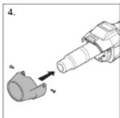
Repair
Changing the hot air tool
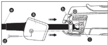
If the hot air tool is faulty, it can easily be changed without opening the casing:
- Important! Disconnect tool from power supply.
- Undo screw d and pull off cover cap a
- Release cable grip b
- Undo C mains terminals.
- Pull out cable
- Undo welding nozzle clamping screw and remove nozzle.
- Undo screw below guide carriage (diagram on p. 2 - O)
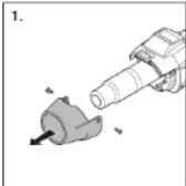
- Remove tool
- Remove (co.
- Passive (feel
- Remove fastening screws from the left and right of the heat shield.
- Remove hot air tool from the heat shield.
- Fit new tool.
- Re-tighten fastening screws on the heat shield.
- Re-tighten screw on guide carriage.
- Fit nozzle and tighten clamping screw,
- Fit new tool and secure in reverse order (4. Firmly screw down mains terminals etc.).
Changing the heating element
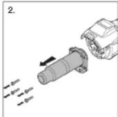
- Important! Disconnect tool from power supply.
- Undo welding nozzle damping screw and remove nozzle.
- Undo screw below the guide carriage (O).
- Pull hot air tool out of the guide carriage.
- Remove fastening screws from the left and right of the
heat shield. - Remove hot air too from heat shield.
- Remove 4 screw from outlet puzzle
Detach outlet nozzle (Fig. 1). - Fit new outlet nozzle (Fig. 2/3).
- Firmly screw outlet nozzle back on again (Fig. 3).
- Push hot air tool into heat shield.
- Re-tighten fastening screws on the heat shield.
- Push not air tool back into the guide damage
- Tighten screw below the guide carriage (O).
- For flexing parts and lighting compressions
- Re-lit welding nozzle and tighten clamping screw.
(FIG. 1)
Maintenance
Fine dust filter
The hot air tool is fitted with a fine dust filter. To clean it (with compressed air), undo screws, take off cover and remove filter. Now re-fit the filter and tighten screw.
Adjusting the tool for using Resitrix roof-sealing membranes
On leaving the factory, the HG Roof automatic welding machine is configured for welding various brands of PVC and FPO / TPO roof membranes.
To use root membrane from Resitrix, you must change the machine setting as follows:
-
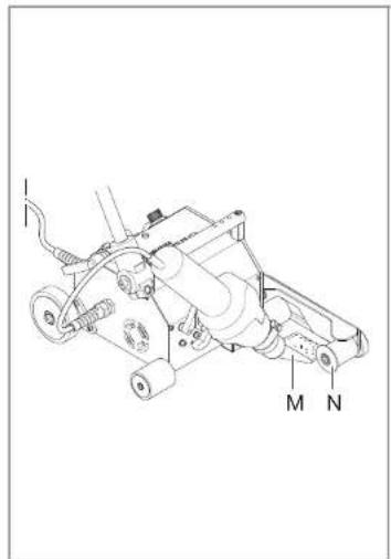
Raise downholder (P)
-
Undo fastening screw on spacer wheel (N)
-
Turn spacer wheel so that it shows "Resitrix"
-
Re-tighten spacer-wheel fastening screw
This change at the downholder (P) also makes it necessary to change the position of the welding nozzle (M):
-
Undo clamping screw below the guide carriage (O)
-
Set hot air tool so it can be moved inwards
without a problem (when moving it inwards, nozzle must not be allowed to contact the upper roof membrane) 3. Re-tighten clamping screw
This adjustment is necessary so as to produce a weld (welding bead) during the welding process. A simple visual check instantly shows you whether you have produced a permanent and watertight joint.
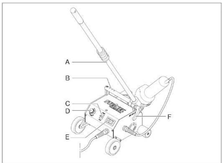
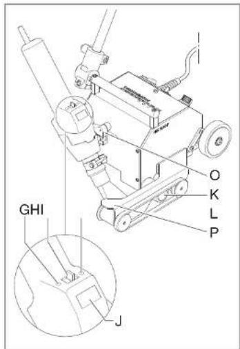
Tool elements
A Telescopic handle
B Carrying handle, complete with holes for attaching additional weights
C START/STOP
D Speed regulator
E Maine switch
F Locking lever for telescopic handle
G Airflow rate mode
H Joystick
I Programme selector
J Display
K Pressure roller
L Hold-down belt
M Welding nozzle
N Spacer wheel
O Guidie carriage
P Downholder
Disposal
Electrical and electronic equipment, accessories and packaging must be recycled in an environmentally compatible manner.

EU countries only:
Under the current European Directive on Waste Electrical and Electronic Equipment and its implementation in national law, electrical and electronic equipment no longer suitable for use must be collected separately and recycled in an environmentally compatible manner.

Declaration of Conformity
(see page 69)
Technical specifications
| Dimensions (H × L × W) | 351 × 432 × 358 mm (with hot air tool turned inwards) |
| Input voltage | 220-230 V |
| Frequency | 50/60 Hz |
| Output | approx. 2000 W maximum |
| Temperatures | 50-620°C (digital control with temperature indicated on the display) |
| Airflow rate | adjustable (30-100%) |
| Emission sound pressure level | < 70 dB(A) |
| Total vibration level | < 2.5 m/s ^2 / K = 0.09 m/s ^2 |
| Protection class | I |
| Speed | 1.5-5 m/min |
| Weight | approx. 14 kg + 3 × 1.1 kg additional weights |
14 - - 15
Manufacturer's Warranty
This STEINEL product has been manufactured with utmost care, tested for proper operation and safety and then subjected to random sample inspection. STEINEL guarantees that it is in perfect condition and proper working order. The product is guaranteed for 12 months or 10,000 hours of operation commencing on the date of sale to the consumer. We will remedy defects caused by material flaws or manufacturing faults. The warranty will be met by repair or replacement of defective parts at our own discretion. This warranty does not cover damage to wearing parts, damage or defects caused by improper treatment or maintenance nor does it cover breakage as a result of the product being dropped. Further consequential damage to other objects shall be excluded.
Claims under warranty shall only be accepted if the product is sent fully assembled and well packed complete with sales receipt or invoice (date of purchase and dealer's stamp) to the appropriate Service Centre or handed in to the dealer within the first 6 months.
Repair service:
If defects occur outside the warranty period or are not covered by warranty, ask your nearest service station for the possibility of repair.

Veiligheidsuitrusting
L Cinghle contentive
natural_image
Two-step diagram showing mechanical assembly steps: first with tool, second with clamping mechanism (no text or symbols)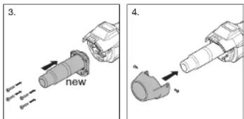
EU Declaration of Conformity
Declaration of Conformity with European Community Directives
(Geschäftsleitung / Chief Executive Officer)
Herzebrock-Clarholz
Datum / Date

- GB Translation of the original operating instructions
- Safety precautions
- Read and observe this information before using the tool. Failure to observe the operating instructions may result in the tool becoming a source of danger.
- About this document
- First time of use
- Take the ambient conditions into account.
- Protect yourself from electric shock.
- Store your tools in a safe place.
- Use by children is not recommended.
- Do not overload your tools.
- Risk of falling
- Beware of toxic gases and fire hazards.
- Operation only under supervision.
- Personal protection
- Repairs by a qualified electrician only
- Damage to the mains power cord.
- Residual heat indicator
- Keep these safety precautions with the tool.
- For your safety
- Tool description - operation
- Proper use
- Getting started
- Power cord and extension cable
- Positioning the tool
- Starting the tool
- Welding process
- Preparing to weld
- Starting to weld
- Guiding the machine during the welding process
- Finishing welding
- Switching OFF machine
- Setting the temperature
- Setting airflow rate
- Programming modeF
- Memory function
- Repair
- (FIG. 1)
- Maintenance
- Fine dust filter
- Adjusting the tool for using Resitrix roof-sealing membranes
- Tool elements
- Disposal
- EU countries only:
- Declaration of Conformity
- Manufacturer's Warranty
- Repair service:
- Veiligheidsuitrusting
- EU Declaration of Conformity
Brand : STEINEL
Model : HG Roof Two
Category : Welding machine