20072 - Welding machine Güde - Free user manual and instructions
Find the device manual for free 20072 Güde in PDF.
User questions about 20072 Güde
0 question about this device. Answer the ones you know or ask your own.
Ask a new question about this device
Download the instructions for your Welding machine in PDF format for free! Find your manual 20072 - Güde and take your electronic device back in hand. On this page are published all the documents necessary for the use of your device. 20072 by Güde.
USER MANUAL 20072 Güde
That the following Appliance complies with the appropriate basic safety and health requirements of the EC Directive based on its design and type, as brought into circulation by us.
In a case of alternation of the machine, not agreed upon by us, this declaration will loose its validity.
Machine description:
Applicable EC Directives: - 2006/95/EC
-2004/108/EC
Date/Authorized Signature:
Before putting the machine into operation please read this guide for operation carefully.
A.V.1
Surplus print even in shortened version requires permission.
Technical changes reserved.
The machine
Welding machines for manual welding in the protective gas with automatic wire feeding allow joining the metallic parts by fusing the edges being joined as well as the additive material. The fusion is generated by an electric arc that comes up between the welded material and the metallic wire that continuously protrudes from the end of the burner and serves as an additional material for joining the parts. Higher welding current allows welding of thicker sheet metal. We do not warrant for damages caused by neglecting of these instructions.
Welding machine in the protective gas MIG 155/6W
Compact higher-class welding machine for handymen. Based on 6 shifting levels it is suitable for problematic welding too. With continuously adjustable wire feeding and plentiful accessories.
Equipment:
Welding shield and reducer valve with single pressure indicator. Including 2 rolling casters at the rear, protection against thermal overload and the hose set of the 2m length.
Scope of delivery
MIG 155/6W Fig.1
- Welding machine with protective gas MIG 155/6W
- Grounding cable
- Hose set
- Reducer valve
- Line cord
- Welding shield
Warranty
Titles for in-warranty performance in accordance with warranty sheet attached.
General safety instructions
It is necessary to read the whole guide for operation before the first use of the machine. In case of any doubts associated to the connection and operation of the machine contact the producer (service department).
TO MAINTAIN THE HIGH LEVEL OF SAFETY PLEASE OBSERVE THE FOLLOWING INSTRUCTIONS:
ATTENTION!
Turned-on period
The machine capacities are represented by the data "Einschaltdauer/Turned-on Period" (ED%) at the machine type plate, i.e. the ration between the welding time and the cooling time. This factor changes for the same machine in accordance to the load conditions, i.e. according to issued welding current. It determines how long the machine can operate at the listed welding current under load and it is always related to the time period of 10 minutes. For example at welding current for ED 60% the machine operates continuously for 6 minutes and after this period an idle phase follows to cool down the internal parts, and then the protection against thermal overload activates again.
Using welding machines and performing welding tasks could represent a risk both for the person operating the machine and for other persons. Therefore the person operating the welding machine is unconditionally obliged not only to read the safety regulations presented here but also to know them and to follow them. It is necessary to bear always in mind that cautious and well instructed operator who strictly adheres its obligations is the best provision against injuries.
Before connecting, preparation, use or transport or the machine you should read regulations listed in the following text and obey them.
INSTALLATION OF THE MACHINE
- Installation and maintenance of the machine must be performed in accordance to local safety regulations.
-
Observe the state of wear the cables of interconnection elements and plugs. If damaged they should be replaced. Perform regular maintenance of the machine. Use only cables that are of sufficient cross-section.
-
Connect the grounding cable as close to the workplace as possible.
- Under no circumstances the machine may not be used in damp environment. Ensure that the workplace is dry in the area of welding and that also objects that are found here including the welding machine itself are dry.
PERSONAL PROTECTION AND PROTECTION OF THIRD PERSONS
Radiation and neat are generated during the welding process therefore it is necessary to ensure the use of suitable protective means and to take precautions to protect both himself/herself and third persons.
Never expose yourself or any other persons to the effects of electric arc or hot metal without necessary protection.

Take care of exhaustion of welding fume and possibly proper ventilation of welding workplace.
PREVENTIVE MEASURES AGAINST FIRE AND EXPLOSION
Incandescent parts of slag and sparkles could cause a fire. Fire and explosion represent additional risks. They can be avoided by meeting these precautions:
- Do not use the machine in immediate proximity of easily inflammable materials like wood, chips, "varnishes", solvents, petrol, kerosene, natural gas, acetylene, propane and similar combustible materials must be removed from the workplace and its ambient or possibly protected from sparkles.
- Suitable extinguishing agent should be ready nearby as a measure to extinguish a fire.
- Do not perform welding or cutting tasks on closed vessels or pipes.
- Do not perform welding or cutting tasks on vessels and pipes even when they are open if they contain or contained materials that could explode or caused other dangerous reaction under the influence of heat or damp.
INSTALLATION OF THE WELDING MACHINE
When installing the machine the following regulations must be observed:
The operator must have a free access to control elements and connecting points of the machine.
It is not advisable to install the machine in close-spaced rooms: Sufficient ventilation of the welding machine is very important. When installing avoid heavily dusted or dirty areas where the machine could aspirate the dust or other objects.
The machine (including cables) may neither form an obstacle in passing nor keep other person from their work.
- The welding machine may be operated only on a flat base and the gas cylinder used for its operation should be properly secured.
Procedure in case of emergency
Perform first-aid measures corresponding to the type of injury and call the qualified medical aid as soon as possible. Protect the injured person from other bodily harm and becalm him/her.
Marking on the machine
Explanation of symbols
The following symbols are used in this guide or on the machine:
Safety of the product:
| CE | |||||
| The product is in accordance with relevant standards of the European Community |
Restrictions:
| Ban, general(in connection with other pictogram) | Fire, open source of light and smoking forbidden | Tugging the cable forbidden | Do not use the machine in wet conditions |
Caution:
| ! | |||||
| Caution/Attention | Warning from dangerous electrical voltage | Caution-danger of tumbling over | Warning from gases harmful for health | Warning from hot surface |
Orders:
| Wear protective shoes | Wear protective gloves | Wear protective clothing | Wear the shield for face protection | Pull out the mains plug before opening | Read the guide for operation before use |
Environmental protection:
| PAP | |||||
| Do not litter the waste freely, after their selection dispose them expertly. | The packaging material from the cardboard can be handed in for recycling at points intended for that. | Electric or electronic appliances that are damaged or intended for disposal must be handed over for recycling at points intended for that. |
Packaging:
| J | II | I | |||
| Protect from moisture | Orientation on the packaging upwards | Attention fragile |
Technical specifications:
| 230 V | 400 V | |||
| Connection to the mains | Weight 230 V 400 V |
Specific for the product:
| —— | —— | |||||
| Welding transformer | Safeguard of the mains | Thermal protection |
Use in accordance with designation
The welding machine for welding inside the protective gas intended to thermal joining of iron - metals by fusing the edges and feeding the additional material.
In case that either instructions implying from universal regulations or instructions contained in this guide are not observed, the producer cannot assume responsibility for any damage.
Residual risks and preventive measures
Mechanical residual risks
| Threat Description Protective measure Residual risk | |||
| Punching, incision Hands may be punched with a wire. | Use protective gloves or perhaps also keep your hands in safe distance from wire output | ||
| Splashing of liquids splashing drops | ps when welding could cause burns. | Wear protective clothes and welding mask. | |
Electrical residual risks
| Threat Description Protective measure Residual risk | ||
| Direct contact with electricity Direct contact with electricity by damp hands could cause an electric shock. | Avoid touching by damp hands and be particular about proper grounding. |
Thermal residual risks
| Threat Description Description | Residual risk | ||
| Burns, frost-bites Contact with hose | e nozzle and with piece being treated could cause burns. | The hose nozzle and piece being treated should be cooled after operation ended first. Wear protective gloves. | |
| Danger from radiation | |||
| Threat Description Protective measure Residual risk | |||
| Infrared, visible and ultraviolet light | Electric arc generates infrared and ultraviolet radiation. | Use suitable protective welding shield, protective clothes and protective gloves. | |
| Danger from the material being treated and other substances | ||
| Threat Description Protective measure Residual risk | ||
| Contact, aspiration Prolonged aspiration of welding gases could be harmful for health. | When working use an exhaustion facility or work in areas with good ventilation. Avoid direct inhalation of gases. | |
| Fire or explosion Hot slag and sparkles could cause a fire. | Never operate the machine in the environment where a fire could occur easily. | |
| Other dangers | |||
| Threat Description Protective measure Residual risk | |||
| Slipping, tipping up, or fall of persons | Cables and hoses could be the cause of tripping up and falls. | Keep the workplace in order.. | |
| Disposal |
| Instructions for waste disposal implying from pictograms that are located on the machine or possibly on the packaging. The explanation of such signs can be found in chapter “Marking on the machine”. |
| Requirements for operators |
The operator must read the guide for operation carefully before any use the machine.
| Qualification |
No special qualification except detailed instruction session led by an expert is necessary for use of the machine.
| Minimum age |
The machine may be operated by persons older than 18 years only. The exception when operation of the machine by a juvenile person is the case when the machine is used during a special training to get skills under supervision of a trainer.
| Training |
For the operation of the machine just corresponding instruction is required. No special training is necessary.
| Technical specifications |
| MIG 155/6W - #20072 | ||
| Voltage | 230 V | |
| Frequency | 50 Hz | |
| Max. power output of the mains | 5,7 kVA | |
| Fuse | 16 A | |
| Voltage of idle run | 48 V | |
| Adjustment range | 25-130 A | |
| Turned-on period | 130 A ~ 10 % 75 A ~30 % | |
| Max. wire thickness | 0.6-1.0 mm | |
| Insulation class | H | |
| Protection type | IP 21 S | |
| Shifting levels | 6 | |
| Weight approx. | 25 kg | |
| Product No. 20072 | ||
Transport and storage

Attention: The machine may be used and stored in straight operation position (on the plane base). Please respect the symbols on the cover!
Ensure that gas cylinder is properly fixed and closed.
Assembly and putting into operation for the first time
Assembly set 1 - assembly of casters and shanks: Fig. 2, Fig. 3, Fig. 4, Fig. 5
Assembly set 2 - Machine holder assembly: Fig. 6
Assembly set 3 - Gas cylinder installation: Fig. 7, Fig. 8
Assembly set 4 - Welding shield assembly: Fig. 9, Fig. 10
Safety instructions for putting into operation for the first time Fig. 11
- Welding helmet
- Welding pinafore
-
Welding gloves
-
Pay attention to sufficient safeguarding of electric supply.
- Wear specified protective clothing (fig.11).
Make sure that no other persons are present in the work area or in possible dangerous area. - Pay attention to avoid any inflammable material in the work area.
- Insert the plug into the corresponding socket, the socket must be secured by a fusible cut-out or power protective switch.
The mains cable and possible extending cables must be at least of the same crosscut. - ATTENTION! Electric safety is ensured only on the condition that the machine is properly connected to effective grounding equipment in accordance to regulations for electrical equipment in force.
- Make sure that useful mains voltage and frequency correspond to the data specified at the machine type plate.
Procedure
When assembling individual parts proceed in the illustrated order.
Keep proper arranging of assembly parts according to figures. The machine has not been workable yet. Open the gas flow t the pressure of 5-7 l/min. Protect the gas output from wind blasts. In addition to that it is necessary to bear in mind the following information too: First levels of the switch 1-2 serve for welding of thin sheet metals while other levels server for thicker walls. At any change of the switch level also the wire feeding speed should be adjusted. If a drop forms at the end of the wire during welding the speed of wire feeding must be increased, on the other hand if you feel the pressure of the wire against the hose you should decrease the speed. Because parts being just welded are very hot always use pliers in case you want to move them and remove sediments at the end of the burner. As soon as the electric arc ignites hold the hose approx. at angle of 30^ in relation to the perpendicular.
Threading of the welding wire Fig.12
- Open upper lid of welding machine and secure the lid with safety pin.
- Insert the coil with welding wire so that the wire can be drawn into feeding straight.
Caution: Pay attention that the wire does not unroll from the coil and its end is flat and without any burr. The coil resistance can be adjusted at clamping nut in the centre.
3) Open the knob (fig. 13 - A)
4) Lift the stirrup element (fig. 13 - F).
5) Check whether grooves at the wire feeding pulley correspond to the wire diameter, in case of necessity turn the revolving handle (fig. 13 - B) counter-clockwise, remove the pulley and insert it into correct groove. Now seat the stirrup element (fig.13 - F) and tighten the revolving knob (fig. 13 - A) until the wire coils up uniformly. If the wire slips off the pulley tighten the knob even further. Attention: Do not tighten too tightly otherwise the excessive pressure to the pulley could cause damage to the wire feeding motor.
6) Now turn the welding machine on.
7) Then, after ensuring the performance of all safety measures, set the switch (fig. 21/1) to level 1 and wire feed adjustment (fig. 21/2) to level 1.
8) Remove gas and stream nozzles and holding the pressure switch on the hose depressed let the wire protrude from it (when the hose is tensed fig. 18). Than replace stream and gas nozzles again back.
9) Adjust the necessary amount of gas at the fittings of the gas cylinder.
Tip: (0.6 mm-wire → 6 l/h); (0.8 mm-wire → 8 l/h); (1.0 mm-wire → 10 l/h)
10) Now the machine is ready for welding.
General information on welding in protective gas
The main area of use in workshops, universal use, suitable both for thinner sheet metals and for thicker materials. A rule holds that the more welding levels are in the machine the better is its utilisation in work with sheet metal. Necessary accessories: gas mixture Co 2/Argon, welding wire, welding shield, reducer valve. It fits also for aluminium and high-grade steel VA when using a suitable gas and wire. (Pure argon/VA-wire/aluminium wire), potentiometer.
Operation
MIG 155/6W Fig. 13
- Adjustment of welding level
- Adjustment of wire feeding speed
- Hose connection
- Grounding clamp connection
- Mains connection plug
- Pilot lamp, thermal protection
- Pilot lamp, operation
Safety instructions for operator
- Start using the machine only after having read the guide for operation carefully.
- Respect all safety cautions provided in the guide.
- Behave responsibly towards other persons.
- Attention!!! Never use corroded welding wire.
Step-by-step guide
The zone to be welded should be free of any rust and varnish. Always use protective welding shield, protective welding gloves and suitable protective clothing. The angle of the hose position towards the treated piece should be approx. 30 degrees.
- Grind bright large surface at the processed piece in the areas of weld seam and connection of grounding clamp.
- Now clamp the grounding clamp to the prepared place of treated piece.
- Adjust parameters of the welding machine in accordance to the user table for welding (chap. 3).
- Adjust required gas volume at the gas cylinder fittings.
- Tip: (0.6 mm-wire → 6 l/h); (0.8 mm-wire → 8 l/h); (1.0 mm-wire → 10 l/h)
- If you have worn a complete protective clothes you may start welding.
Fig. 14
Fig. 15
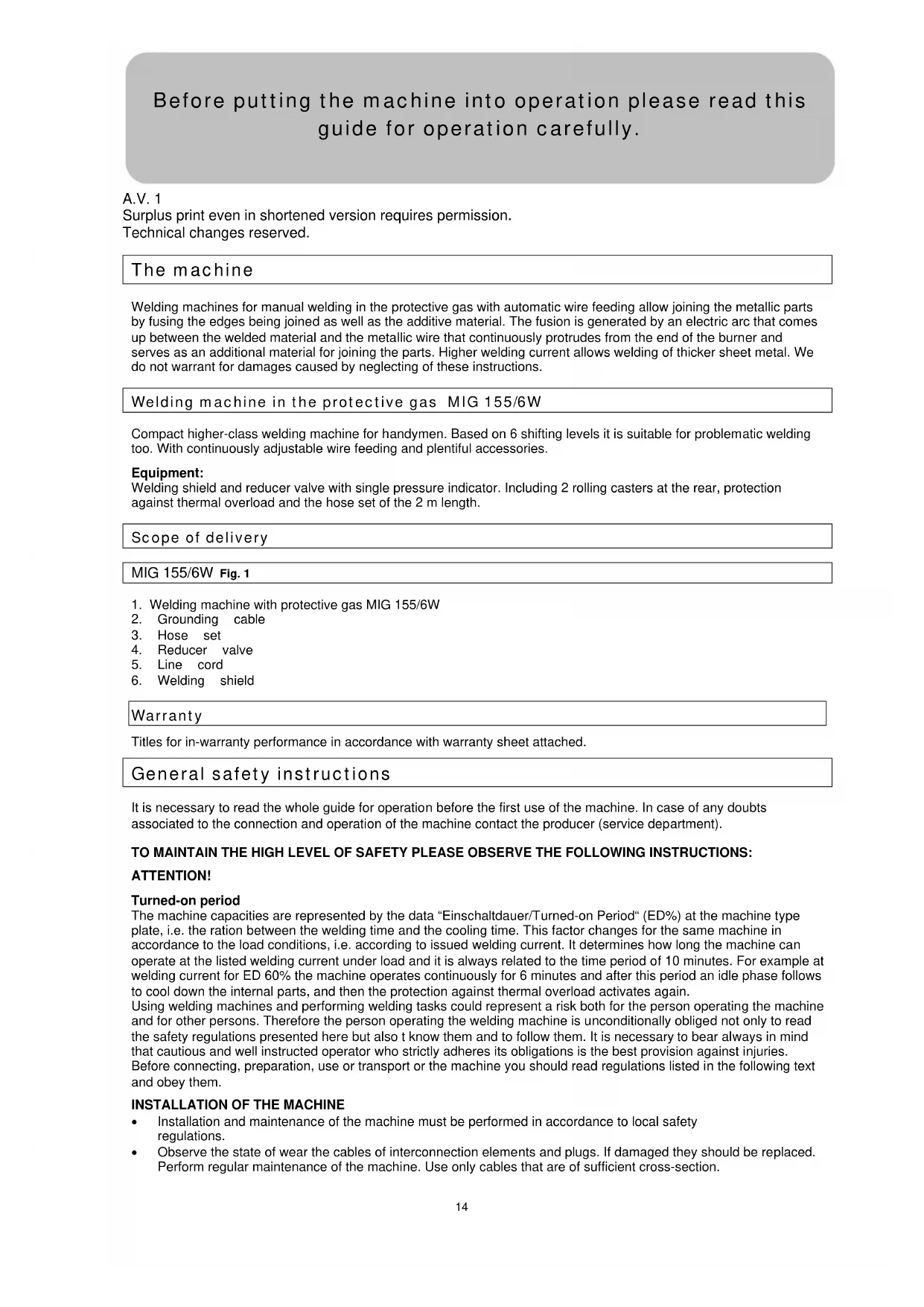
Tip: Before starting your own task please perform a trial welding to get an optimum adjustment of the welding achieving an optimum result.
Parameters for welding are set to optimum in case that a uniform noise can be heard and the welded seam has good penetration into the material, namely it is relatively flat.
Tips for welding
| Fault Cause and remedy Example | ||
| Piece being treated is curved | 1. Bad preparation of seam2. Straighten the edges and fix (fasten) for welding | |
| Weld reinforcement | 1. Idle run voltage too low2. Welding speed too low3. Improper adjacent angle of the welding burner4. Wire too thick | |
| Small layer of metal | 1. Too high welding speed2. Too low voltage for the welding speed | |
| Welds have oxidized appearance | 1. Weld in a pit at long electric arc2. Adjust the voltage3. Wire is warped or it protrudes from the wire guide too much4. Improper wire feeding speed | |
| Insufficient fusing of the root | 1. Irregular or insufficient distance2. Improper adjacent angle of the welding burner3. Wire guide tube worn-out4. Too low wire feeding speed or welding speed | |
| Penetration | 1. Wire feeding speed to high2. Improper adjacent angle of the welding burner3. Distance too large | |
The zone to be welded should be rid of rust and varnish. The burner is selected according to the type of material. It is recommended to try the strength of current on a defective piece first.
Faults - Causes - Elimination
| Fault Cause Elimination | ||
| Welding current drops out | 1. - Protection against excessive temperature fell out due to overload. | 1. Protection against excessive temperature will perform automatic reset after cooling the transformer (approx. after 10 minutes, take care of ED!) |
| Welding current not available at all. Protective power switch or RCD fell out | 1. Mains fuse fell out 1. Let the fuse checked | 2. Turn the protective output power switch on3. Turn the RCD on |
| Welding current is not available . | 1. Bad contact between grounding clamp and welded part2. Rupture in grounding cable or grounding line3. Rupture in burner line | 1. Clean and grind the welded area and surface of the part.2. Repair or replace the grounding cable.3. Repair or replace the burner. |
| Wire feeding motor does not operate, pilot lamp is on. | 1. Fuse is burnt.2. Toothed rim is faulty or blocked.3. Motor is defective. | 1. Replace the 2 A-fuse.2. Replace the toothed rim.3. Replace the motor (contact customer service). |
| Wire feeding motor does not work, Pulleys rotate. | 1. The pressure to the pulley is not adjusted properly.2. There is dirt, dust etc. on the stream nozzle of the burner.3. Gas nozzle is defective.4. The wire is warped.5. Inner tube of the wire guide is dirty or damaged. | 1. Adjust the pressure to pulleys correctly.2. Clean the machine contact tube. Use an air compressor to do so, in case of heavy contamination replace the contact tube3. Replace the gas nozzle and check the tip.4. Check the pulley pressure and adjust it properly if necessary.5. Clean with compressed air and let the hose replaced if necessary. |
| Wire feeding is irregular. | 1. Dirt at the wire guide. Gas nozzle is worn-out or defective.2. Gas nozzle is clogged.3. An obstacle restrains the wire feeding pulleys guiding.4. Wire feeding pulleys guiding has deformed.5. Improper tension of the wire | 1. Clean the machine wire guide using an air compressor.2. Replace the gas nozzle or contact tube.3. Clean or replace the gas nozzle.4. Clean the wire feeding pulleys.5. Replace the wire feeding pulleys.6. Adjust the wire tension properly. |
| Electric arc burns in unstable way. | 1. Improper wire speed adjustment2. Dirt at the welded place.3. Gas nozzle is worn-out or defective. | 1. Adjust the wire speed according to recommended systems.2. Clean or polish the welded surface.3. Replace the gas nozzle and check the tip. |
| Welded joint is porous. | 1. No gas2. Nozzle holder is blocked3. Material is rusty or damp4. Burner is too far or you hold it at incorrect angle towards the point being welded. | 1. Open the gas and adjust the gas intake flow.2. Clean or replace the gas nozzle.3. Properly treat the place of welding or increase the gas inflow.4. Clean or polish the material.5. Distance between the gas nozzle and processed piece must be 8-10 mm and the hose should be held at an angle of 30°.6. Check the rubber hose, connection and hose set assembly. - Depress the gas nozzle into proper position. |
| Welding wire stops in proximity of stream nozzles | 1. Stream nozzle is worn-out.2. Welding wire is warped.3. Wire feeding speed is too low. | 1. Replace the stream nozzle.2. Check the pulley tension pressure.3. Follow the instructions for wire feeding speed. |
| Welding pressure is irregular | 1. Welding wire blocked on the coil 1. Check the p | pressure of pulley tension and adjust if necessary. |
| Too weak penetration | 1. Welding current too weak2. Electric arc too long | 1. Increase the welding current and wire feeding.2. The hose should be held near the piece being processed. |
| Too strong penetration | 1. Welding current too high2. Wire feeding speed too slow3. Improper distance of the burner from piece being processed | 1. Reduce the welding current and wire feeding.2. The burner should be moved calmly and uniformly.3. The distance of the nozzle from the piece being processed must be 8-10 mm. |
Inspection and maintenance
Maintenance of hose set
Regular maintenance must be performed to ensure faultless function of hoses.
Gas nozzle must be sprayed by protective spray for nozzles and remove sediments inside regularly.
For this case the following steps should be performed (see Fig. 26):
-
Remove the nozzle (1) by pulling it forward.
-
Remove sediments that formed from welding slug, from the nozzle.
- Spray it with protective spray for nozzles.
- If the nozzle is rusty, it must be replaced.
Maintenance of Stream nozzle
For this case the following steps should be performed (see Fig. 26):
- Remove the nozzle (1) by pulling it forward.
- Unscrew the stream nozzle (2)
- Check whether the hole that the wire goes through is not too wide, before reassembly replace it if required.
- Depress the button at the hose so that the wire goes out and then assembly the stream nozzle back.
Maintenance of nozzle holder Fig.16
For this case the following steps should be performed (see Fig. 26):
- Openings for gas exhaustion could be slightly clogged, in such a case it is necessary to remove the gas nozzle by its pulling off (1),
- then unscrew the stream nozzle (2),
- unscrew the gas distributor (3) and replace it with a new one.
Safety instructions for pro inspection and maintenance
Only regularly maintained and treated machine can become a reliable assistant. An insufficient care and maintenance could be the cause of unforeseen injuries and accidents.
Inspection and maintenance plan
| Time period Description Other | possible details | |
| Regularly | • Maintenance of the hose set (blowing off and cleaning of inner tube of the wire guide, pulley for wire feeding, gas nozzle and gas distributor) | |
Spare parts
| GB | Do you have any technical questions? Any claim? Do you need any spare parts or operating instructions? We will quickly help you and without needles bureaucracy at our web pages at www.guide.com in the Servicing part. Please help us be able to help you. In order to identify your device in case of claim we need the serial No., product No. and year of production. All this data can be found on the type label. Please enter it here for future reference: Serial No._ Product No.: Year of production | ||
| Tel.: +49 (0) 79 04 / 700-360 | Fax: +49 (0) 79 04 / 700-51999 | E-Mail: support@ts.guide.com | |
EC Declaration of Conformity
Güde GmbH & Co. KG
We herewith declare, Birkichstraße 6, 74549 Wolpertshausen, Germany
That the following Appliance complies with the appropriate basic safety and health requirements of the EC Directive based on its design and type, as brought into circulation by us.
In a case of alternation of the machine, not agreed upon by us, this declaration will loose its validity.
Machine description: - MIG 155 6W
Article-No.: - 20072
Applicable EC Directives: - 98/37 EC
Applicable harmonized Standard:
- 2006/95/EC - 2004/108/EC
- EN 60974-1
-EN 609784-10
Point of certification:TÜV Rheinland Product Safety GmbH, Am Grauen Stein, D-51105 Köln
Date/Authorized Signature: 19.09.08

That the following Appliance complies with the appropriate basic safety and health requirements of the EC Directive based on its design and type, as brought into circulation by us.
In a case of alternation of the machine, not agreed upon by us, this declaration will loose its validity.
That the following Appliance complies with the appropriate basic safety and health requirements of the EC Directive based on its design and type, as brought into circulation by us.
In a case of alternation of the machine, not agreed upon by us, this declaration will loose its validity.
Makine tipi: - MIG 155 6W
Machine description:
Urün no.: - 20072
Article-No.:
Applicable EC Directives: - 2006/95/EC
- 2004/108/EC
Date/Authorized Signature:
That the following Appliance complies with the appropriate basic safety and health requirements of the EC Directive based on its design and type, as brought into circulation by us.
In a case of alternation of the machine, not agreed upon by us, this declaration will loose its validity.
Oznaceni pristroju:
-MIG1556W
Machine description:
Zbožić.: - 20072
Article-No.:
Applicable EC Directives: - 2006/95/EC
- 2004/108/EC
Date/Authorized Signature:
That the following Appliance complies with the appropriate basic safety and health requirements of the EC Directive based on its design and type, as brought into circulation by us.
V pripe, ze budu na pristroji vykonane zmeny bez konzultacie s nami, straca toto vyhlasenie svju platnost'.
In a case of alternation of the machine, not agreed upon by us, this declaration will loose its validity.
Oznacenie pristrojov: - MIG 155 6 W
Machine description:
Tovar c.: - 20072
Article-No.:
Prisluşné smernice EU: - 98/37 EC
Applicable EC Directives: - 2006/95/EC
- 2004/108/EC
Date/Authorized Signature:
INSTALLATIE VAN HET APPARAAT
EC Declaration of Conformity
Hiermede verklaren wij, Gude GmbH & Co. KG
We herewith declare, Birkichstraße 6, 74549 Wolpertshausen, Germany
That the following Appliance complies with the appropriate basic safety and health requirements of the EC Directive based on its design and type, as brought into circulation by us.
In a case of alternation of the machine, not agreed upon by us, this declaration will loose its validity.
Machine description:
Article nr.: - 20072
Article-No.:
Applicable EC Directives: - 2006/95/EC
-2004/108/EC
Gebrukte harmoniserende
normen: - EN 60974-1
Applicable harmonized - EN 609784-10
Standard:
Plaats van certificeren TUV Rheinland Product Safety GmbH, Am Grauen Stein, D-51105 Köln
Datum/Handtekening fabrikant: 19.09.08
Date/Authorized Signature:
Manuale step by step
EC Declaration of Conformity
That the following Appliance complies with the appropriate basic safety and health requirements of the EC Directive based on its design and type, as brought into circulation by us.
In a case of alternation of the machine, not agreed upon by us, this declaration will loose its validity.
Machine description:
N^ articolo: - 20072
Article-No.:
Applicable EC Directives: - 2006/95/EC
- 2004/108/EC
Date/Authorized Signature:
That the following Appliance complies with the appropriate basic safety and health requirements of the EC Directive based on its design and type, as brought into circulation by us.
In a case of alternation of the machine, not agreed upon by us, this declaration will loose its validity.
Machine description:
Applicable EC Directives: - 2006/95/EC
- 2004/108/EC
Date/Authorized Signature:
EC Declaration of Conformity
that the following Appliance complies with the appropriate basic safty and health requirements of the EC Directive based on its design and type, as brought into circulation by us.
In a case of alternation of the machine, not agreed upon by us, this declaration will loose its validity.
Oznaka uredaja: - MIG 155 6W
Machine Description:
Art.br.:-20072
Article-No.:
Applicable EC Directives: - 2006/95/EC
- 2004/108/EC
Primijenjene harmonizirane
norme: - EN 60974-1
Applicable harmonized - EN 609784-10
Standards:
Mjesto certifikacije:TÜV Rheinland Product Safety GmbH, Am Grauen Stein, D-51105 Köln
Datum/Poptis proizvodača:
19.09.08
Date/Authorized Signaure:
Podaci o potpisanoj osobi Gospodin Arnold, Geschäftsführer
Title of Sinatory:
Pred uvedbo naprave v pigeon natančno preberite priloženo navodilo za uporabo.
A.V.1
that the following Appliance complies with the appropriate basic safety and health requirements of the EC Directive based on its design and type, as brought into circulation by us.
In a case of alternation of the machine, not agreed upon by us, this declaration will loose its validity.
Machine description:
Articlel st.: - 20072
Article-No.:
Uporabne smernice EU: - 98/37 EC
Applicable EC Directives: - 2006/95/EC
- 2004/108/EC
Date/Authorized Signature:
Podatki o podpisniku: Gospod Arnold, Geschäftsführer
Title of Signatory:
EC Declaration of Conformity
Prin prezenta declaram, Gude GmbH & Co. KG
We herewith declare, Birkichstraße 6, 74549 Wolpertshausen, Germany
That the following Appliance complies with the appropriate basic safety and health requirements of the EC Directive based on its design and type, as brought into circulation by us.
In a case of alternation of the machine, not agreed upon by us, this declaration will loose its validity.
Marcareutilaj: -MIG1556W
Machine description:
Articol nr.: - 20072
Article-No.:
Directive UE aferente: - 98/37 EC
Applicable EC Directives: - 2006/95/EC
-2004/108/EC
Norme aplicabile armonizate: - EN 60974-1
Applicable harmonized - EN 609784-10
Standard:
Loc de certificare: TÜV Rheinland Product Safety GmbH, Am Grauen Stein, D-51105 Köln
Date/Authorized Signature:
Date despite semnatar: DI. Arnold, Director
Title of Signatory:

MepknBcIyauHa npOn3weDCTBHe
B cnuyai Ha npon3weDCTBne daTe Ha noctpaadnna Heo6xOdmata nbpBa nomau H3BnKaIte KOJIKO To M0e no6b30 KBAHnHUPaHa JekapcKa NOMou. PepNa3e Toctpaadnna O T dpyn HapaHbAHn u ro ycnokoi Te.
06o3NaueHnHa anapata
06aCHEHHe Ha cMbONITE
B TOBA pkoBOOCTBO n/nn Ha anapata ca n3noJ3BaHn CneHNTe CmBONI:
CnpynoCT Ha npOn3BedeHneTo:
| CE | |||||
| Проблеменeto OTROВая на СъOTВЕТНИЕ HOPМВ EC |
3a6paHEno:
MexAHnHeCKN OCTaTbUHn ONaCHOCTN
TOnnnHHOCTaTBHn ONaCHOCTN
TpaHcnpT ncklaHnpaHe

BbHMaHHe: AnapaTbT MoKe da 6bDe n3non3BaH nCKnaDnpaH cMo B paBHO pa60THo noIOJKeHne (Ha paBeH
noi).Cb06pa3aBaIte ce mona cbc CmBOnIte Bbpxy onakOBkata!
Iocnype Ta0BaTa 6ytuNka da 6bJe do6pe yKpeHa n 3aTBOpena.
MOHTaJnIbPBo NyckaHe B EKcNlOaTaun
MOHTAXHa rpyna 1-MoHTax Ha KOJIeIaTa u KpaYeTa:ΦnR.2,ΦnR.3,ΦnR.4,ΦnR.5
MOHTaXHa rpyna 2-MoHTaX Ha dpbXkKaTa Ha anapaTa:Φnir.6
MoHTaxKa rpyna 3- mHctaJauHa ra3oBata 6ytnIka: Hr.7, Hr.8
MOHTAXHa rpyna 4-MoHTax Ha 3abapbHnH nIeM: Hr.9, Hr.10
Hnctpykun 3a 6e3onacnoCT npn nbpBOTO BbBexKaHe B eKcnloataunae
1.3abapbueHJneM
2.3abapbHa MaHTa
3. 3abapbHn pbkabu
CbIIOBaIe da 6bIe DOCTaTbHNO 3aunTeHO eNEKtpueckTo npucbeiHeHne.
- I3noI3BaIte npeIINcaHITe npeIpa3Hn o6JIekla (obr.11)
- IorpnkeTe ce OKoJIO MrcToTo Ha pa60Ta eBentyaHb B onaChata 3OHa Da He Ce HAMnP aT HnKaKbN dpymIuca.
OrledaTe OKoNOMcToTO 3a pa6To Da He Ce HAMnPAT 3anaNTenHmATEpnaHn.
BkapaIte e enceNa B cBoTBeTHnKoHTaKT, KOHTaKTbT Tp8Ba Da 6bDe 3auNTeH C pa3TONrEm npedna3nten Hnn PpeDnaseH nKJIouyBaTeJ Ha MOUHOCT.
Kaebtj3aMpexkatau eBentyauHOn ydbnKnteHnrt Ka6eTpr6Ba da ca Hau-Manko cbc cbtoTo ceueHe.
BHIMAHHE! EneKtpuecketa 6e3onacnoct e ocHypeHa cmo toraba, KoraTo anapaTbTe npabuHcBbp3aH KbM eFeKTnBHO 3a3emraBaIoo CbOpBXeHHe Cnpoei BaJIuHHTe HOPM3a eEneKtpuecknCbOpBXeHn.
- ПювереTe, дали зхаразьшоTo eNeКтпчecко Hanpeжени И чсToTа OTROВаряТ haДаннITE ot TINOBaTa TabeIka ha anapata.
NocJeDoBaTeHNoCT
Pm MOnTnpaHTo Ha OTdEnHInTe yactn Cn3BaIte fInypaJInHaT aocneNoBateJIHOCT.
Cna3BaIte npabunHTo pa3noJoxKeHHe mOnTnpaHInTe qactn cnopeD fHyprnte.AnapaTbT Oue He e noTROTBEN da cyHKUHOHPa.OTBOpTe ra3Ta da n3TuHa C HAnrahe 5-7 J/MnH.N3NyckAHnT ra3 ppeNa3BaIte OT Hanop Ha BAtbp.OCBEN TOBA Tp86Ba Da ce cbO6pa3BaTe Cbc CneHNTE INHOpMaUN: PbPbNTe CTeneHN Ha PpeBknUoyBaTeNl 1-2 cnjka 3a 3abapbaHe Ha TBHKoCTeHn IamapHa, DOKaTO OCTaHaJIte DBe CTeneHN CnyKAT 3a No-de6eJIN CTEHN. PnBcKa npomHa Ha CTeneHIne Ha npEKBIOuBATEJrT6Ba Da ce perynIPA u CKOpocTTa Ha TENoDAbaHEto.AKO np3abapbaHTo Ce 6pa3yBa Ha Kpa HA TeNTa KaKA, Tp86Ba Da ce NobuKNCKOpocTTa Ha TENoDAbaTeHNOyCTBO Ako ObpatHo YvBCTBaTe HATNCK Ha TEHTA npOTNB UHaHa, Tp86Ba Da ce HAMANCKOpocTTa. Tb KaTO TOKU 3abapbaHIne TaCTn Ca MHORO ropeu, N3NoN3BaIte BNHaN KNeu, KORA To NCKaTe Da n Pa3DbVKnTe N da OTCTpaHIne HaHOCIne OT Kpa Ha ropeJkata. BeDHara CneN kato CE anaan enektpueckata Dbra, dpBXTe WnHaRa NOd bTbn OKONO 30^ cnpymo nepneHnkyjra.
IpoBnUaHe Ha 3aBapbHuHaTa TeNΦnr.12
- OTBopTe roHnKa nak Ha 3aBapbUHnAnapat n fo qKcnpaTe C npedna3nHa uΦT.
- TocTaBeTe poKata c63aBapbHnTa TeTtaka, Ye da MoKe TeTTa da 6bDe BkapaHa npaBOJIHeHo B noDaBaTeHnHO yCTPOIcTBo.
Ipeynpexdne: O6bprte BnHMaHe, da He ce pa3BnBa TeTta ot poKkata n KpaTn da 6bpe
paBeH n 6e3 deOpmauN. CbnpotNBHeHnTo Ha poKkata ce perynpa c nomoza
Ha npTgraaTa raiKa Ha dbpxkaa.
3) Pa3BnIte BbptTuaNT ce BNHT (fNr. 13 - A)
4) IOBUNHHeTe NOBnKHOTo pAmO (fur.13-F).
5) PpOBepeTe daJIu IINIOBete B pONkata 3a NODaBaHe Ha TeNTa OTROBaprHa DNAmetbpa Ha TENTa, Ako e Heo6xOIMo 3aBbptTe BbptTaaTe peyka (obr. 13 - B) npOTNB NOCOKATA Ha YacOBHnKOBATA cTpeJika, H3BaJeTe pONkata nI NOCTaBeTe B OTROBaprIaN JIiU. Cera HarnaceTe pAMOTO (obr.13-F) n3aTgAraTe C BbPrrnBnT (obr.13-A),doKaTo TEJa He 3anoue He ca He HABnBa paBHomepHo.AKO TEJa Ce n3XnYe ot polkata, BNHT a OJe npnterHene. BHImAHne: He 3aTgAraTe MHO rCInHO, B npOTNBen CnyaH npeKaaneHOTo HAJIraHe Bbpxy pONkata MoKe Da NOBPeDn MOTopa Ha TeJOnOdaBaTeJIHOTO yCTPOINCTBO.
6) Cera BknyeTe 3aBapbHnAn apaT.
7) CnaI Kato Cte Cnauu Bcunu Mepk 3a 6e3onacHocT, npeBpTe TpeBKnOyBaTeJ (fur. 21/1) Ha 1 ctenen H perynauTHa TeNooDaBaHeTo (fur. 21/2) Ha1 ctenen.
8) CmBkHeTe ra3OBaTa n KOHTaTHata dO3a N HATnCKaKN KONKaT a 3a HnIrahe Ha IJNaHra n3KapaiTe TeNTa (npn onbHaT WnAhr 18).CneToBa KOHTaTHata n Ra3OBaTa dO3a BbPHeTe o6paTHo.
9) HarlaecTe Heo6xOIMOTO KOINueCTBO ra3 Ha apMaTypaTa Ha ra3OBaTa 6yTuNka.
Mn: (0,6 MM-Teπ → 6 π/4); (0,8 MM-Teπ → 8 π/4); (1,0 MM-Teπ → 10 π/4)
10) Cera anapaTbTe noDroTBEN 3a 3abapBaHe.
06uHOpMaun 3a 3aBapBaHe B 3aUnTHa ra3Oba cpea
IJIaBHO Ce n3nOJI3Ba B pa6oTJHInu, HMa yHNBePcAINHO npINIOKeHne, NOxOJaUe e KaKTo 3a TbHKn JAmapHH, Taka n 3a no-De6eJIM MaTePnAn. Baxn npabNtOto, Ye KONKO tOBeue cTeNeHn HMa anapaTbT, TOnKOBa No-ronmO e HerOBOTO npINIOKeHne npin pa60n C JAmapHH.
Heo6xmo 60yBaHe: cme oT ra3 Co 2/AproH, 3aBapbHa TeJ, 3aBapbYeH IJIeM, peDyUpBeHTnI.
Iopxoaduo e 3a anymnHn VA nepupaHa CTOMaHa npu ynoTpeBa Ha noxdoJr r3n Ten. (HcT aproH/VA-ten/anymnhneBa Te), NOTEHNUOMETbp.
06cJyXBaHe
MIG 155/6W _nr .13
- PerynaunHa cteneHTa Ha 3abapBaHe
- PerynaunHa ckopocTa Ha TeIonoJaBaHaTe
- PncbceDnHnTeJ Ha 7naHa
4.Письeннтел Ha 3a3emBaunTe UINKn (maca) - KOHTaKT 3a npncbceDnHeHne KbM MpeKaTa
- KoHTpONHa JAMnA,ToPnnHnHa 3aunTa"
PpeNa3Hm Mepkn 3a cnryphocn npu o6cnykBaHeTo
- I3noI3BaIte anapata yak cIeI TOBa, cIeI KaTO CTe CN IpOueHn BHIMaTeHNO pBkoBOcTBOTO 3a o6cnyKbaHe.
Cna3BaIe BCnKm MepKn 3a CnrypHOCT NomeCTeHN ByytBAHTo.
BbDeTe BdbpKaHHeTo Cn OTROBOPn CnpMaOctHaJIINIua.
BhImaHHe!! Hnkora He n3non3BaIte pIxJaCana 3aBapyHa TeJ.
YnbTbaHe CTbnKa NO CTbnKa
Ha MxCTOTo 3a 3abapbahe He Tp6Ba Da Ima pBxkaI INI 60J. No npnHnI n3non3BaIte npednaeH 3abapbueH WneM, npedna3HN 3abapbUHn pKABuN I NOxOJaIO o6NeKn. BbIbT Ha HAKIoH Ha WnAHa cnpaMo 3abapbaHata Yacst 6n Tp6BaNo Da 6bJe Okono 30 rpaDyca.
1.ИЗшалфайтdo6ляськ roлma ПLOUвьрхуобработванои3делпВOBlaactTаHa 3abapbHnIЯWebIMRCTOTO3aPncBedeINHeHneHa3a3eMBA山ITEUINK.
2. YkpeneTe cera 3a3emBaunTe uNKn Ha NOIrotBeHTo MRCTo Ha o6pa6oTBaHTo n3dJIne.
3. Hactpoite npametpnte Ha 3aBapbHnna anapat cnopek ekcnnoatauioHHnte Ta6nci 3a 3abapraBahe (rnaBa. 3).
4. HactpoTe Heo6xOIMOTO KOINueCTBO ra3 Ha apMaTypaTa Ha ra3OBaTa 6yTuJIka.
5.ндя:(0,6MM-TeN→6π/);(0,8MM-TeN→8π/);(1,0MM-TeN→10π/)
6. Ako Cte ekinnapn C KOMnEeKTHo 3aunTHo 0bJeKNo, MoXeTe Da 3anOuHete Da 3abapBaTe.
Ipei Da 3aOnuHHe NCTINCKOTo 3aBapraBaHe, n3BbPWeTe np6Ha 3aBapKa, 3a Da npOBeprTe npABnHnHa n36Op Ha napameTpTe 3a 3aBapraBaHe e 3a Da NoCTnHHeTe ONTmAlnH pe3yIITaN. Obr.14
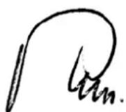
Iapametpnte 3a 3abaprahe ca n36paHn ONTImanHO toraba, KORAto ce CyBa eHaKBO INHTeh3INBEN Wym N 3abapbYHnT WeB IMa do6po
IpoBapraBaHe B MaTePmaHa, ToeCT Ye e CpaBnTeHNo IIOcBk.
Ideu 3a Do6po 3aBapraBaHe
| Дeф ekт i Причин a n O T C T P a n H a B a N e | I I I I I I I I I I I I I I I I I I I I I I I I I I I I I I I I I I I I I I I I I I I I I I I I I I I I I I I I I I I I I I I I I I I I I I I I I I I I I I I I I I I I I I I I I I I I I I I I I I I I I II I I I I I I I I I I I I I I I I I I I I I I I I I I I I I I I I I I I I I I I I I I I I I I I I I I I I I I I I I I I I I I I I I I I I I I I I I I I I I I I I I I I I I I I I I I I I I I I I I I I L | I I I I I I I I I I I I I I I I I I I I I I I I I I I I I I I I I I I I I I I I I I I I I I I I I I I I I I I I I I I I I I I I I I I I I I I I I I I I I I I I I I I I I I I I I I I I I I I I I I II II II II II II II II II II II II II II II II II II II II II II II II II II II II II II II II II II II II II II II II II II II II II II II II II II II II II II II II II II II II II II II II II II II II II II II II II II II II II II II II II II II II II II II II II II II II II II II II II II II II I I I I I I I I I I I I I I I I I I I I I I I I I I I I I I I I I I I I I I I I I I I I I I I I I I I I I I I I I I I I I I I I I I I I I I I I I I I I I I I I I I I I I I I I I I I I I I I I I I II IIII II II II II II II II II II II II II II II II II II II II II II II II II II II II II II II II II II II II II II II II II II II II II II II II II II II II II II II II II II II II II II II II II II II II II II II II II II II II II II II II II II II II II II II II II II II II II II II II II II II II III III III III III III III III III III III III III III III III III III III III III III III III III III III III III III III III III III III III III III III III III III III III III III III III III III III III III III III III III III III III III III III III III III III III III III III III III III III III III III III III III III III III III III III III III III III III III III III III III III III IIIIII III III III III III III III III III III III III III III III III III III III III III III III III III III III III III III III III III III III III III III III III III III III III III III III III III III III III III III III III III III III III III III III III III III III III III III III III III III III III III III III III III III III III III III III III III III III III III III III III III III III Ⅱ |
OT 30HATA 3a 3abapraBaHe 6n Tp8bAo Da ce MaxHe BcKaBa pXkaN 6oR. IopeKATA e N3paHa cnopei Bnda Ha MaTePnAJa. IpenOpBvBame Hau-Hanpei Da ce H3npoBa CnIaT a Ha ToKa Ha deFeKTHO N3deJIe.
EC Declaration of Conformity
CTOBA HnE DeKnapnpame,
Güde GmbH & Co. KG
We herewith declare, Birkichstraße 6, 74549 Wolpertshausen, Germany
Ye KOHcIeIa I KOHcTpyKUraHa Ha NO-DOy ONncaHte Maunnn B TINOBn 3NbJIHeHH, KOnTO Nyckame Ha na3apa, OTROBapr Ha CbOTBeHTne OCHOBHn 3NcKBaHH Ha dIpeKTbBtE Ha EC 3a cnryphoCT n XnRnHeHa.
That the following Appliance complies with the appropriate basic safety and health requirements of the EC Directive based on its design and type, as brought into circulation by us.
B cnyuahn npomha ha maunHaTa, KOrTo He e 6uJa KOHcyItpaHa c Hac, r6u Ta3n deKnapaua BannndocT.
In a case of alternation of the machine, not agreed upon by us, this declaration will loose its validity.
O3HaueHHe Ha MaunHaTa:
-MIG1556W
Machine description:
NoHaapTKyna:
-20072
Article-No.:
AnuHpaHn DnpeKTHBn Ha EC: -98/37/EG
Applicable EC Directives: - 2006/95/EC
-2004/108/EC
AninupaHn xapMOHN3npaHn
CTaHdApTn: - EN 60974-1
Applicable harmonized - EN 609784-10
Standard:
Data/NoDnnc Ha npOn3BODnteJr:
19.09.08
Date/Authorized Signature:
DaHHn 3a noDnncAHn:
Title of Signatory:

rocnoDn APHOJa,ynpaBnteJ