Uni-Mig 270 AS-Pro SYN - Welding machine Güde - Free user manual and instructions
Find the device manual for free Uni-Mig 270 AS-Pro SYN Güde in PDF.

User questions about Uni-Mig 270 AS-Pro SYN Güde
0 question about this device. Answer the ones you know or ask your own.
Ask a new question about this device
Download the instructions for your Welding machine in PDF format for free! Find your manual Uni-Mig 270 AS-Pro SYN - Güde and take your electronic device back in hand. On this page are published all the documents necessary for the use of your device. Uni-Mig 270 AS-Pro SYN by Güde.
USER MANUAL Uni-Mig 270 AS-Pro SYN Güde
Translation of the original operating instructions
ENGLISH Please read the instructions carefully before starting the machine.
EN You can find all the technical documents required in the Ecodesign Regulation 2019/1784 at
https://www.guede.com/index.html?shopart=20127

text_image
QR code image containing encoded data, no visible human-readable textDownloads

Produktinformation

Bedienungsanleitung

EN starting-up the device FR Mise en service IT Messa in funzione
ES Puesta en marcha NL Toestel in gebruik nemen cz Uvedení do provozu
natural_image
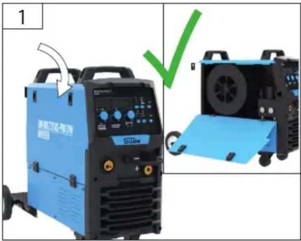
Blue industrial welding machine labeled 'UN-MG 270 AS-PRO SYN INVERER' with control panel and display (no readable text beyond branding)
natural_image
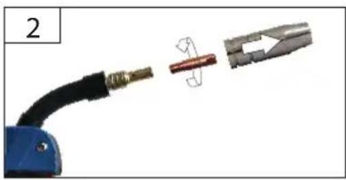
Black welding torch with attached metal clip and two metallic end fittings (no text or symbols visible)
natural_image
Black welding torch with metal clasp and connector (no text or symbols visible)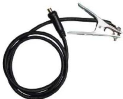
natural_image
Coiled black welding torch with metal clamp (no text or symbols visible)
text_image
TIP optional Art.-Nr. 16924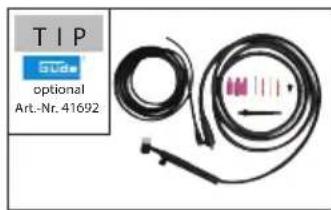
text_image
TIP SDA optional Art.-Nr. 41692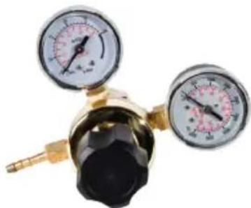
natural_image
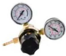
Close-up of a gas regulator with dual gauges and a brass fitting (no visible text or symbols)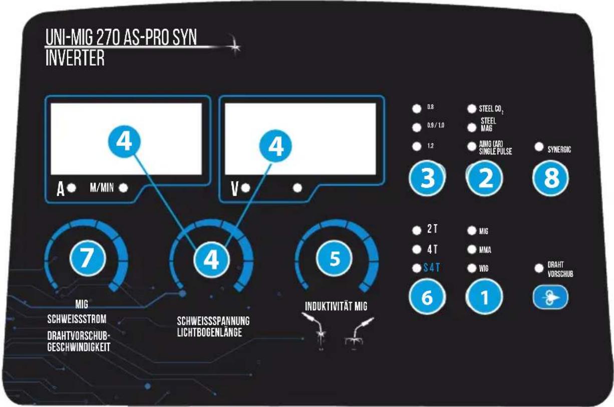
text_image
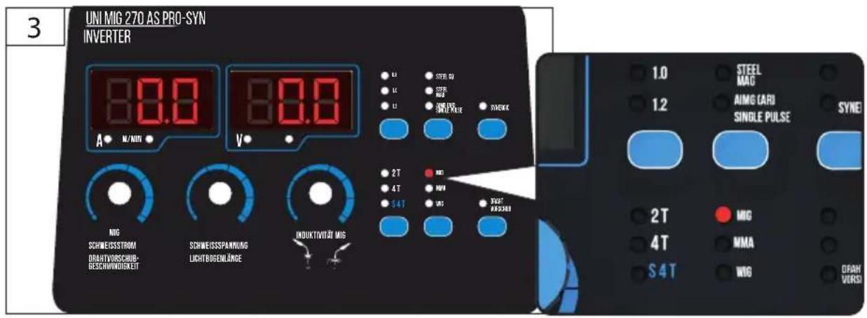
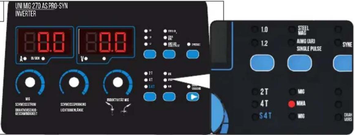
UNI-MIG 270 AS-PRO SYN INVERTER 4 A M/MIN 7 MIG SCHWEISSSTROM DRAHTVORSCHUB- GESCHWINDIGKEIT 4 SCHWEISSSPANUNG LICHTBOGENLÄNGE 5 INDUKTIVITÄT MIG 4 V STEEL CO₂ 0.9 / 1.0 STEEL MAG 1.2 AIMG (ARD) SINGLE PULSE SYNERGIC 3 2 8 2 T MIG 4 T MMA S4 T WIO 6 1 DRAFT VORSCHUB1 MIG/MAG-Schutzgas, MMA-Elektroden, FLUX-Fülldraht, WIG-Wolfram Inertgas Schweissen | MIG/MAG shielding gas, MMA electrodes, FLUX cored wire, TIG tungsten inert gas welding | Gaz de protection MIG/MAG, électrodes MMA, fil fourré FLUX, soudage TIG au gaz inerte tungstène | Gas di protezione MIG/MAG, eletrodi MMA, filo animato FLUX, saldatura con gas inerte di tungsteno TIG | MIG/MAG beschermgas, MMA elektroden, FLUX gevulde draad, TIG wolfraam inert gas lassen | Ochranný plyn MIG/MAG, elektrody MMA, svařovací drát FLUX, svařování wolframovým inertním plynem TIG. | MIG/MAG ochranný plyn, MMA elektródy, zvárací drót FLUX, zváranie TIG wolfrámovým inertným plynom | MIG/MAG védőgáz, MMA elektródák, FLUX töltőhuzal, TIG wolfram védőgázos hegesztés | Gaz osłonowy MIG/MAG, elektrody MMA, drut rdzeniowy FLUX, spawanie metodą TIG z wolframowym gazem obojętnym | Gas de protección MIG/MAG, electrodos MMA, hilo tubular FLUX, soldadura TIG con gas inerte de tungsteno
2 SCHWEISS-GAS AUSWAHL | Welding gas selection | Sélection de gaz de soudage | Selezione del gas di saldatura | Selectie van lasgas | Výber svárovacího plynu | Výber zváracieho plynu | Hegesztógáz kiválasztása | Wybór gazu spawalniczego | Selección del gas de soldadura
3
Schweissdrahtdurchmesser | Wire diameter | Diamètre du fil | Diametro del filo | Draad diameter | Prümër drátu | Priemer drótu | Huzal átmérője | Hitrost premika žice | Promjer žice | Диаметър на проводника | Diametrul sâmei | Пречник жице | Šrednica drutu |
Diámetro del cable
4 Schweiss-Spannung. Lichtbogenlänge MMA/WIG/MIG/MAG | Welding voltage, arc length MMA/WIG/MIG/MAG | Tension de soudage, longueur d'arc MMA/WIG/MIG/MAG | Tensione di saldatura, lunghezza d'arco MMA/WIG/MIG/MAG | Lasspanning, booglengte MMA/WIG/MIG/MAG | Svařovací napětí, délka oblouku MMA/WIG/MIG/MAG | Zváracie napätie, dlžka oblúka MMA/WIG/MIG/MAG | Hegesztési feszültség, ívhossz MMA/WIG/MIG/MIG/MAG | Napięcie spawania, długość łuku MMA/WIG/MIG/MAG | Tensión de soldadura, longitud de arco MMA/WIG/MIG/MAG
Drosselung, regelt den Schweissstromanstieg bei Dünnblechschweissen | Throttling, regulates the increase in welding current for thin sheet metal welding | Étranglement, régule l'augmentation du courant de soudage lors du soudage de tôles fines | Throttling, regola l'aumento della corrente di saldatura per la saldatura di lamiere sottili | Smoren, regelt de toename van de lasstroom voor het lassen van dun plaatwerk | škrcení, reguluje nárůst svářovacího proudu pro svářování tenkých plechů | škrtenie, reguluje zvýšenie zváracieho prúdu pri zváraní tenkých plechov | Duzzasztás, szabályozza a hegesztési áram növekedését vékony fémlemezek hegesztésénél | Dławienie, reguluje wzrost prądu spawania w przypadku spawania cienkich blach | Throttling, regula el aumento de la coriente de soldadura para la soldadura de chapas finas
6 Schweissprozess —> S.9 | Welding process -> p.9 | Processus de soudage -> p.9 | Processo di saldatura -> p.9 | Lasproces -> p.9 | Proces svařování -> str.9 | Proces zvárania -> str.9 | Hegesztési folyamat -> p.9 | Proces spavania -> str. 9 | Proceso de soldadura -> p.9
7 Schweiss-Strom MMA/ WIG/MIG/MAG, Drahtvorschubgeschwindigkeit | Welding current MMA/TIG/MIG/MAG, wire feed speed | Courant de soudage MMA/TIG/MIG/MAG, vitesse d'avance du fil | Corrente di saldatura MMA/ TIG/MIG/MAG, velocità di avanzamento del filo | Lasstroom MMA/ TIG/MIG/MAG, draadaanvo -ersnelheid | Svařovací proud MMA/TIG/MIG/MAG, rychlost posuvu drátu | Hegesztési áram MMA/TIG/MIG/MAG, huzaltovábbítási sebesség | Duzzasztás, szabályozza a hegesztési áram növekedését vékony fémlemezek hegesztésénél | Prąd spawania MMA/TIG/MIG/MAG, prędkość podawania drutu | Corriente de soldadura MMA/TIG/MIG/MAG, velocidad de alimentación del hilo
8 SYNERGIC S.10
text_image
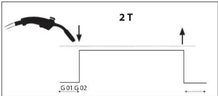
2 T G 01 G 02natural_image
Illustration of a blue welding torch emerging from an open cardboard box, with an upward arrow indicating motion (no text or symbols present)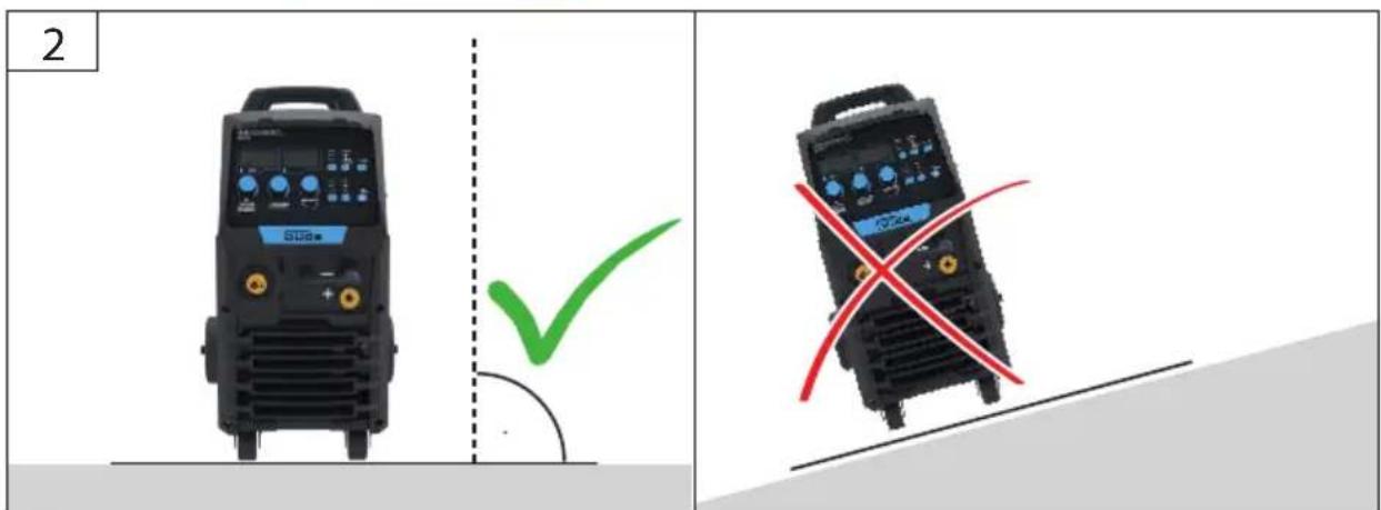
text_image
2 STUa ✓ STUa X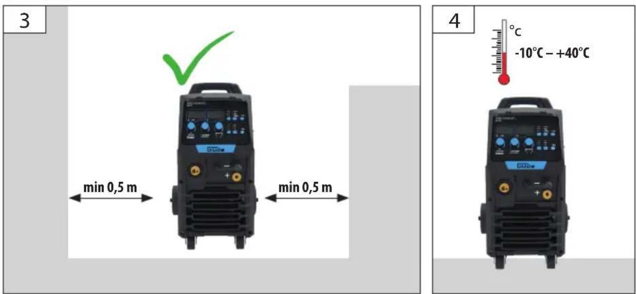
text_image
3 min 0,5 m min 0,5 m 4 -10°C - +40°C
natural_image
Close-up of a gas regulator with two pressure gauges and a black connector (no visible text or symbols)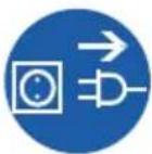


MIG/MAG

WIG
text_image
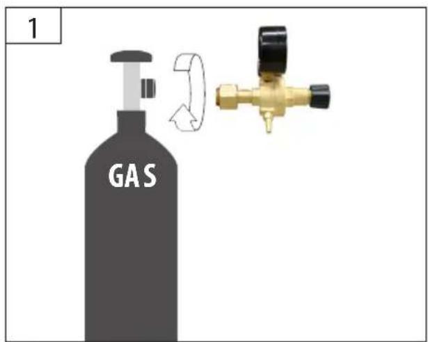
1 GAS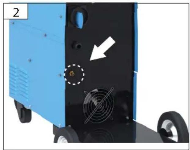
natural_image
Close-up of a blue industrial machine with fan blades and a white arrow pointing to a circular feature (no text or symbols visible)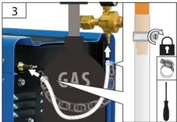
text_image
3 GAS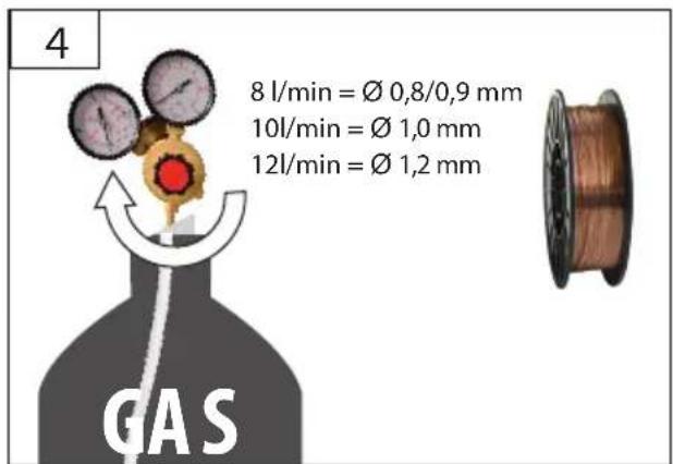
text_image
4 8 l/min = Ø 0,8/0,9 mm 10l/min = Ø 1,0 mm 12l/min = Ø 1,2 mm GAS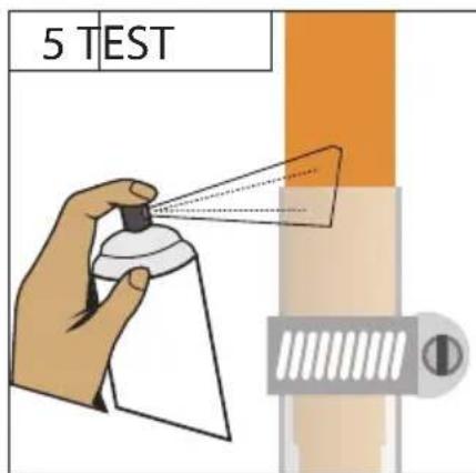
text_image
5 TEST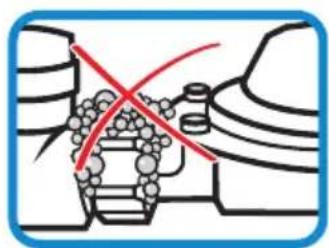
natural_image
Diagram of a mechanical assembly with no visible text or symbols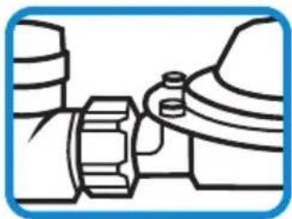
natural_image
Pure mechanical assembly diagram without any text, numbers, or symbols
MIG/MAG

natural_image
Close-up of a wire spool being inserted into a mechanical component, with no visible text or symbols.natural_image
Close-up of a mechanical device with visible gears and shafts, no readable text or symbols


MIG/MAG

natural_image
Three types of electrical cable connectors and a wire coil, shown in separate views (no text or symbols visible)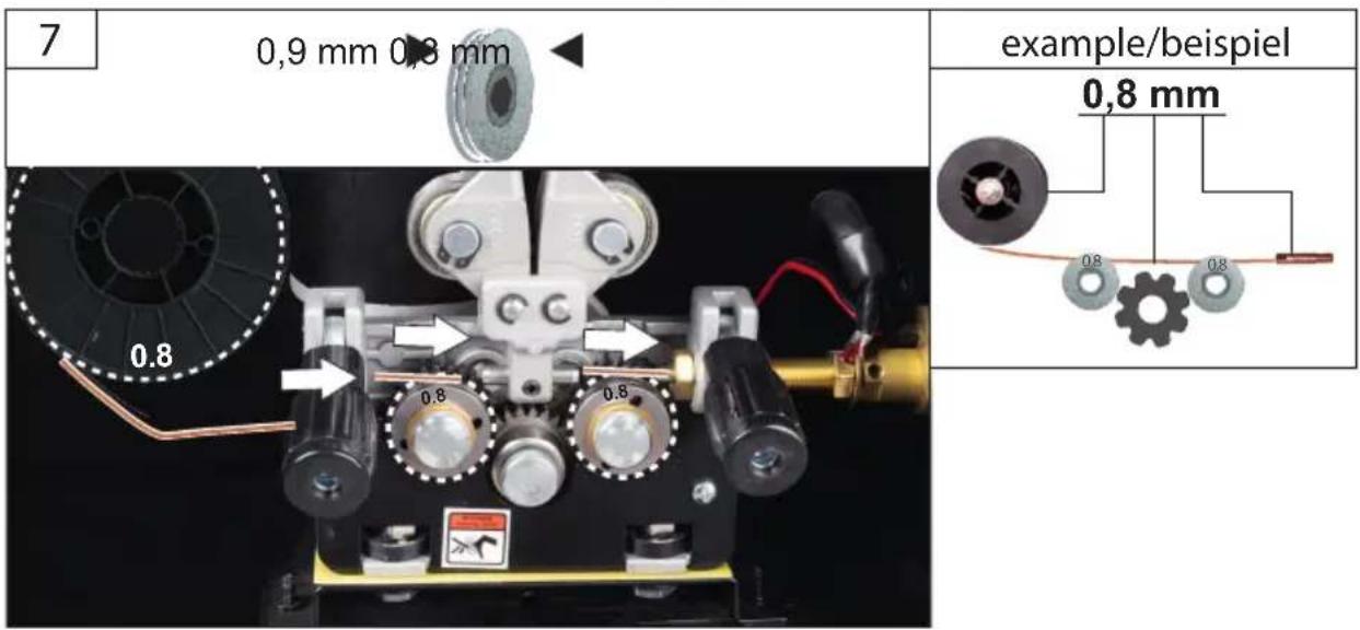
text_image
7 0,9 mm 0,8 mm example/beispiel 0,8 mm 0,8 mm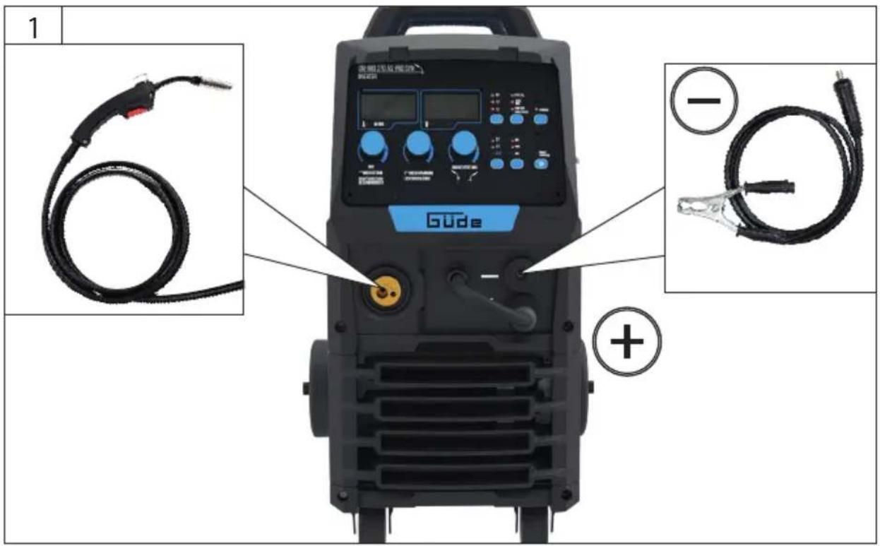
text_image
1 Gude +

natural_image
Close-up of a blue welding torch connector with a red cable and a gray plastic clamp attached (no text or symbols visible)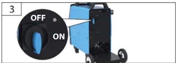
text_image
3 OFF ON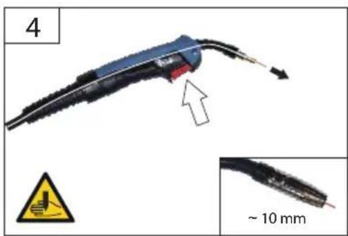
natural_image
Close-up of a mechanical component with a red arrow indicating a feature, shown with an inset warning sign and scale bar (no text or symbols on the main subject)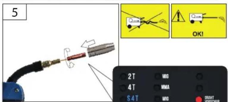
text_image
5 OK! 2T MIG 4T MMA S4T WIO DRAHT VORSCHUB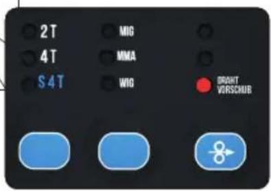
text_image
2T 4T S4T MIG MMA WIG DRAHT VORSCHUB
natural_image
Diagram of a mechanical lever interacting with a surface, showing textured surfaces and a central pivot (no text or symbols)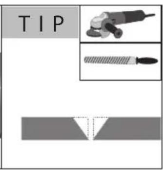
text_image
TIP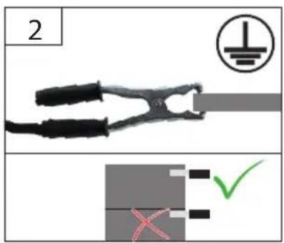
text_image
2 ① X = ✓


text_image
3 UNI MIG 270 AS PRO-SYN INVERTER 80.0 80.0 A • M/MW • V • NIG SCHWEISSSTROM DRAFTVORSCHUB- BESCHWINDIGREIT SCHWEISSPAMMUNG LIGHTBOGENLÄNGE INDUKTIVITÄR MIG LE LE LE STER DU STER MAE DRINK RICE POENKK 2T 4T 54T NO MW WG 301F AS3361 1.0 STEEL MAG AIMG CARB SINGLE PULSE SYNEJ 2T MIG 4T MMA WG OFAH VERSI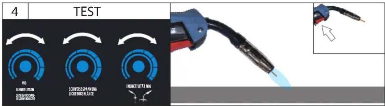
text_image
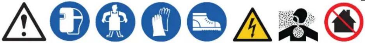
Warning symbols and pictograms including warning, hazard, safety, and no-hanging household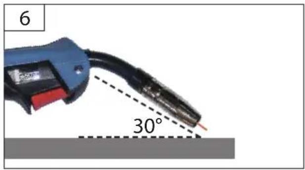
text_image
6 30°
natural_image
Close-up of a welding torch with a flame, showing the tip and base (no text or symbols visible)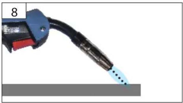
natural_image
Close-up of a black fuel nozzle with blue tip and red handle, emitting light trail (no text or symbols visible)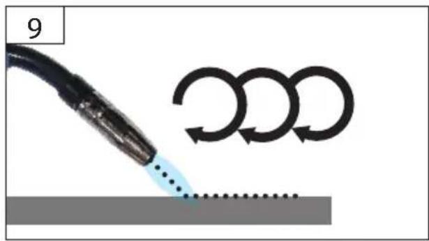
text_image
9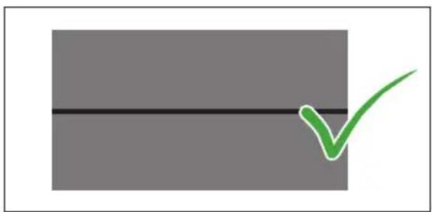
natural_image
Simple diagram with a black horizontal line and a green checkmark on a gray rectangle (no text or symbols)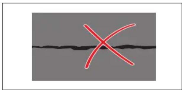
text_image
X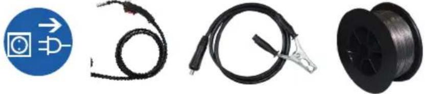
natural_image
Four different types of electrical connectors and wires: a blue circular sign with a power symbol, coiled cable, black wire with clamp, and a black spool (no text or symbols visible)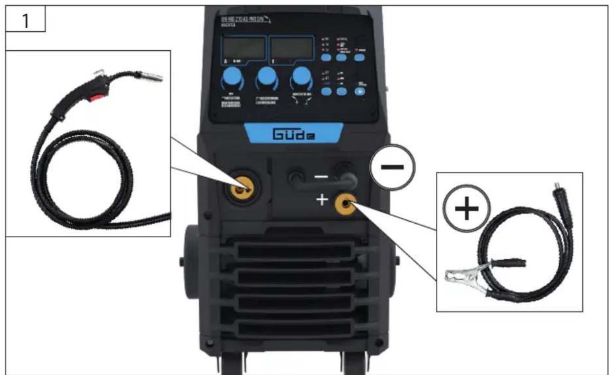
text_image
1 Gude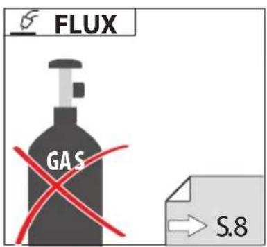
natural_image
Three black industrial clamps with metal contacts and connectors, shown from different angles (no text or symbols visible)

1
text_image
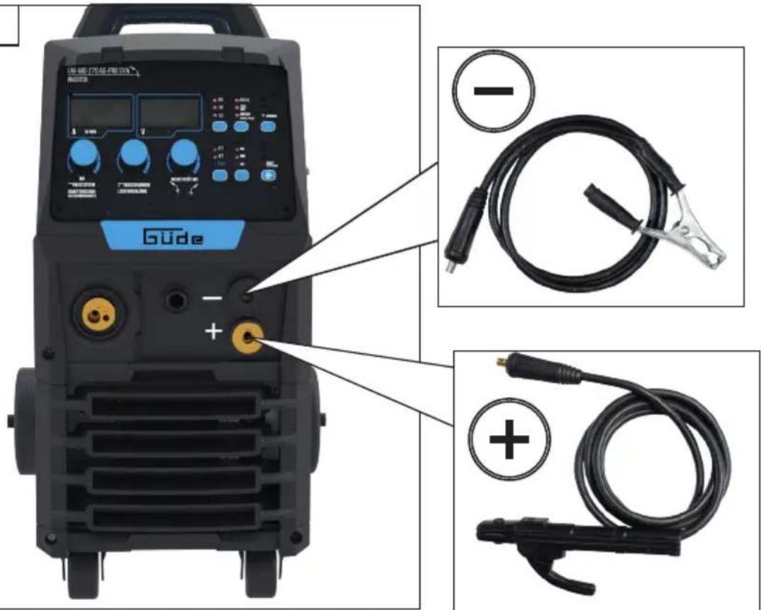
Gude - - +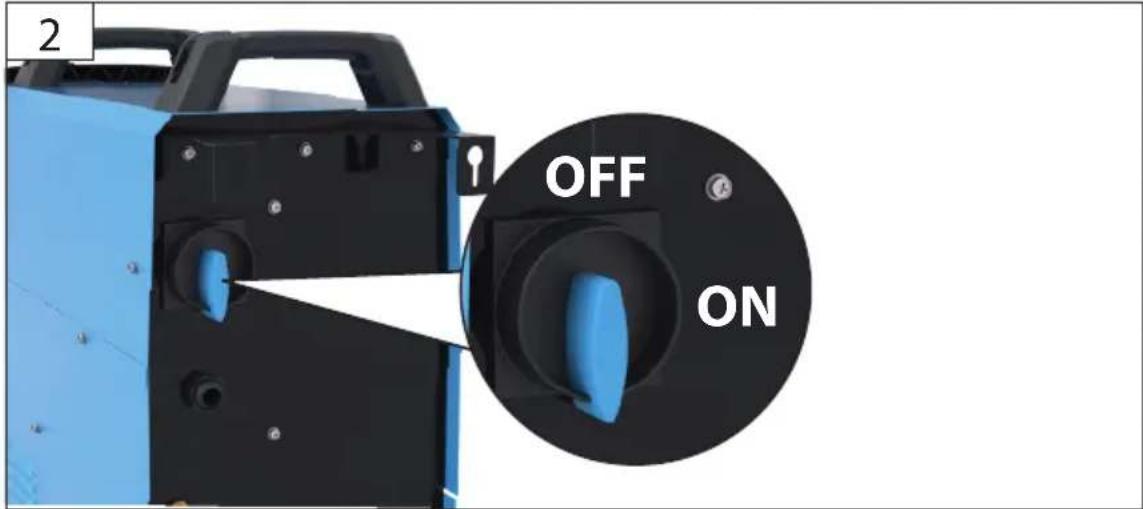
text_image
2 OFF ON


3
text_image
UNI MIG 270 AS PRO-SYN INVERTER 8.0.0 8.0.0 A • M/MIN • V • MIG SCHWEISSSTRON DRANTVORSCHUB- GESCHWINDIGREIT SCHWEISSSPANUNG LICHTBOGENLÄNGE INDUKTIVITAT MIG 35 13 12 STEELG. 圈 12 鑑組LEF SYNEIS 2T 4T 54T MG MGH KIE TRAVEN VEGETR STEEL MAG AIMG (ARD) SINGLE PULSE SYNE 2T 4T S4T MIC MMA MIG DRAN VIRS
TIP
Art.-Nr. 16928
natural_image
Pure diagram of parallel lines with no text, numbers, or symbols4
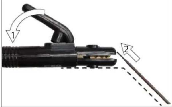
text_image
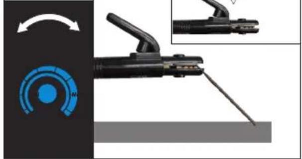
Diagram of welding torch with labeled parts and directional arrows indicating movement or force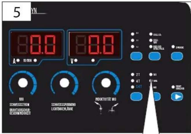
text_image
5 5YN_ A • M/MIN • 8.0.0 8.0.0 V • Mio SCHWEISSSTROM DRAHTVORSCHUB- GESCHWINDIGKEIT SCHWEISSSPÄNNUNG LICHTBROENLÄNGE INDUKTIUTÄT Mio 2 T 4 T 5 T STILLER: FULL AVG/AD OVERNATR. SPRINGR MA MA MA MA CAHT VÖRCKR PTEST
natural_image
Close-up of a welding torch tool with blue circular dial indicator and magnified view showing internal components (no text or symbols)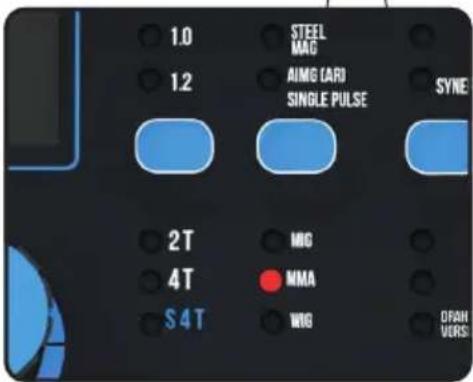
text_image
1.0 STEEL MAG 12 AIMG (AR) SINGLE PULSE SYNE 2T MGO 4T NMA S4T WIG DRAH VORSI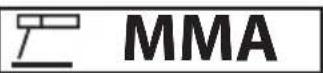
text_image
Warning symbols and pictograms including warning, hazard, safety, and no-hanging household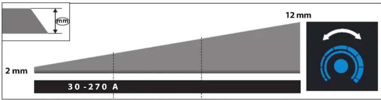
text_image
12 mm mm 2 mm 30 - 270 A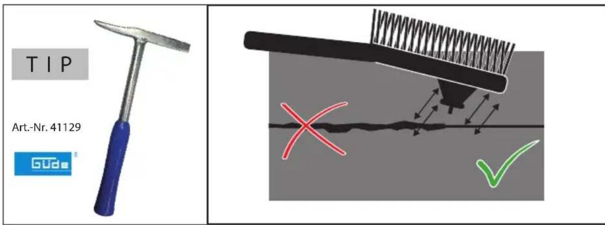
text_image
Warning symbols and pictograms including warning, hazard, safety, and no-hanging household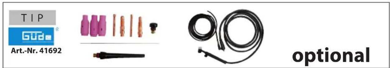
natural_image
Close-up of a welding torch with a pink tip and white base, emitting sparks (no text or symbols visible)
text_image
Warning symbols and pictograms including warning, safety, and household restriction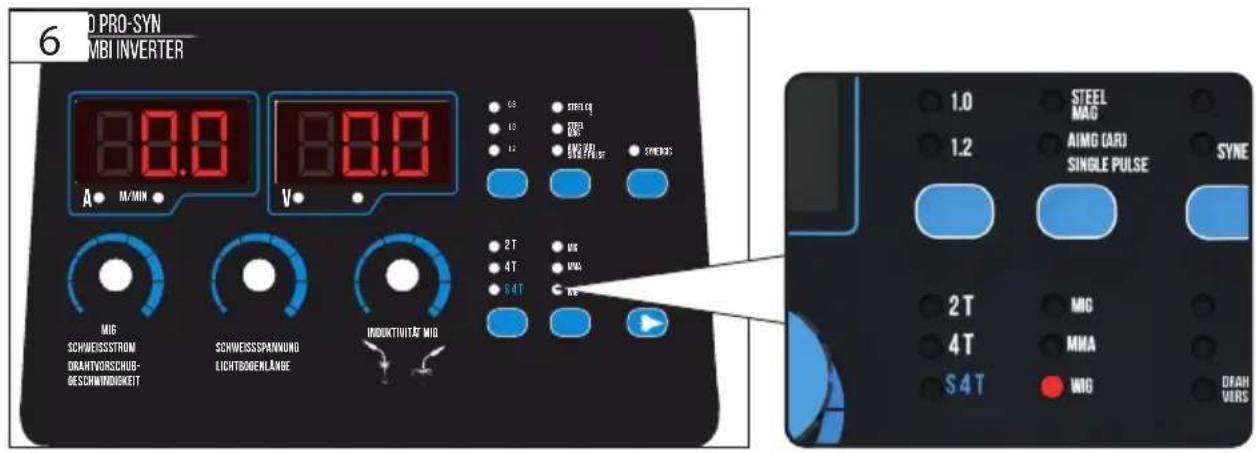
text_image
6 D PRO-SYN MBI INVERTER 80.0 A • M/MIN MIG SCHWEISSSTROM DRAHTVORSCHUB- BESCHWINDIGKEIT SCHWEISSSPANUNG LICHTBOGENLÄNGE INDUKTUTAT MIG 80.0 V 2 T 4 T 5 4 T STEEL Q1 R2 FEBER SYNE30 US UAC UAC RE STEEL MAG AIMG (ARI) SINGLE PULSE SYNE 2 T 4 T 5 4 T MIG MMA MIG DEAH VERS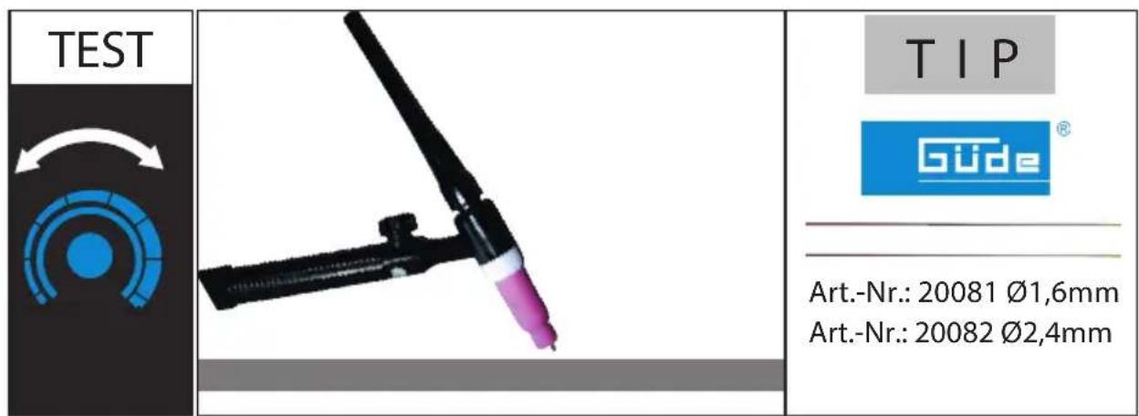
| Welder Uni Mig 270 AS-Pro Syn | |
| Art. No 20127 | |
| Degree of protection IP 21S | |
| Insulation class H | |
| Rated input voltage (AC Current) U_1 | 400 V |
| Mains frequency 50/60 Hz | |
| Protection, time delay 16 A | |
| No-load voltage U_0 | 63 V |
| Idle state power 20 W | |
| Efficiency of the Welding Power Source 89 % | |
| Switch-on time X * 60 % | |
| max. Welding current (400 V) 270 A | |
| Regulated section Welding current 30-270 A | |
| Max. input (400 V) 6,4 kW | |
| Material thickness 2,0 mm-20 mm | |
| Wire thickness | 0,8 -1,0 mm (1,2 mm) |
| Dimensions L x W x H | 800 x 450 x 650mm |
| Weight | 42 kg |
| This appliance is made of the following recyclable materials: | |
| Sheet steel, Ccopper, Aluminum, ABS, PE | |
* The ratio of given duration time/the full-cycle time. Switch-on time determined at 40°C using simulation


Read and understand the operating instructions before using the appliance. Abide by all
the safety measures stated in the service manual. Act responsibly toward third parties. In case of any doubts about connection and operation refer please to our customer center
Specified Conditions Of Use
Welder in protective atmosphere for thermal connection of ferrous metals by melting edges and including mixture. Please note that the device is designed for domestic use only.
Do not use this product in any other way as stated for normal use. Not observing general regulations in force and instructions from this manual does not make the manufacturer liable for damages. Please note that our equipment has not been designed for commercial, craft or industrial use. If the equipment is used in commercial, craft or industrial operation or for similar activities, we cannot assume any.
Safety instructions

WARNING! Electric shock! There is a risk of injury caused by electric shock!

Operation is only allowed with a safety tch against stray current (RCD max. stray rent of 30mA).
IP21 protection degree of the welder. The welder must not be exposed to rain and moisture when being operated or stored.
Check the voltage. Technical data given on the type label must correspond with electric network voltage. Insert the plug of the electrical cable in a socket of suitable shape, voltage and frequency complying with current regulations.
Use extension cables with a maximum length of 5 meters and with a cable cross-section of not less than 1.5 mm2. Use of extension cables of different length and cross-section and also of adapters and multiple sockets should be avoided.
Check the cable and/or socket for damages before the appliance putting into operation.
Defective cable or plug may cause electric shock. Do not pull the service cable to pull the plug out of socket. Do not expose yourself or other persons without protection to electric arc or hot metal. Spraying
welding pearls may cause burns. A suitable welding shield, protective clothes and protective gloves to be worn at all times.
Long-term inhalation of welding gases may be harmful to your health. Work with an exhaust system or in well ventilated spaces. Avoid direct inhalation of gases.
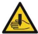
Contact with the hose bundle nozzle and the material being processed may cause burns. Special welding gloves to be worn at all times.
Let the hose bundle nozzle and the material being processed cool down after being operated.
Long-term working with the appliance may damage hearing. Hearing protection to be used at all times.
Welder may only be used on a flat surface and with a properly secured gas bottle.
Make sure the welding smoke is exhausted or the place of welding ventilated well.
Hot slag and sparks may cause fire or explosion. Never use the appliance in a flammable environment.
Wood, sawdust, "varnishes", petrol, kerosine, natural gas, acetylene, propane and similar flammable materials must be removed from the place of work and the surrounding area or protected against sparks flying away. To extinguish fire, a suitable fire extinguisher must be made ready nearby.
No welding or cutting on closed vessels and pipes.
No welding or cutting on vessels and pipes if they are open, containing materials able to explode due to heat or moisture or able to cause other dangerous reactions. Never use the welder to defrost frozen pipes.
The gas bottle must necessarily be secured against falling. The welder must never be lifted together with the gas bottle. Special regulations apply to the transport of gas bottles.
Handling of gas bottles
Make sure the gas bottles are used and stored in rooms with sufficient air inlet and outlet.
A leaking gas bottle may reduce the share of oxygen in the inhaled air and therefore represent a risk of suffocation. Before use, make sure the gas bottle contains gas designed for the work being done.
Gas bottles must always be safely fixed in a vertical position on a wall support or on a specially manufactured gas bottle cart.
The bottle with shielding gas and the fixed adjustment gas current equipment must not be moved. The gas bottle valve must be closed during transport.
Close the gas bottle valve after use.
Instructions for the installation and operation of an arc welding device to prevent possible electromagnetic interference:
As the manufacturer, we recommend that the following assessments and measures be carried out by a qualified electrician.
General
The user is responsible for setting up and operating the arc welding machines/cutting equipment in accordance with the manufacturer's instructions. If electromagnetic interference is detected, it is the responsibility of the user of the arc welding machines/cutting equipment to find a solution with the technical assistance of the manufacturer. In some cases, the measure needed may simply consist of earthing the welding circuit (see note). In other cases, it may include complete electromagnetic shielding of the power source of the arc welding machine/cutting equipment and the workpiece, combined with input filters. In all cases, electromagnetic interference must be reduced until it no longer causes any disturbance.
Note
The approach taken to earthing the welding circuit depends on the local safety regulations.
Changing the earthing to improve electromagnetic compatibility may increase the risk of accidents or
damage to equipment
Assessing the surroundings
Before setting up the arc welding machines and/or cutting equipment, the user must assess possible electromagnetic problems in the surroundings. When doing so, the following factors must be taken into account:
a) other mains cables, control cables, signal and telecommunication cables above, below and next to the arc welding machines and/or cutting equipment;
b) Audio and television broadcast transmitters and receivers;
c) Computers and other control devices;
d) Safety equipment, e.g. protection for commercial facilities;
e) the health of persons nearby, e.g. those using pacemakers and hearing aids;
f) Calibration and measurement equipment;
g) the resistance of other equipment in the vicinity to interference. The user must ensure that
other equipment used in the environment is suitable for such a purpose. This may require additional
protective measures;
h) the time of day during which the welding, cutting, or other activities must be carried out.
The extent of that surrounding area that must be considered depends on how the building is constructed, and the other activities taking place there. This area may extend beyond the limits of the premises
Evaluation of the welding machine / cutting equipment
In addition to the assessment of the area, the arc welding machines/cutting equipment can be evaluated to assess and resolve cases of interference. An assessment of electromagnetic interference should include in situ measurements, as specified in section 10 of CISPR 11:2009. In-situ measurements can also be made to gauge the effectiveness of any minimisation measures implemented.
Guidance for minimisation measures:
Public power supplies
Welders machines/cutting equipment should be connected to the public power supply as per the manufacturer's recommendations. If there is any interference, it may be necessary to take additional precautions, such as fitting filters for the mains connection. Consider shielding the mains cable of permanently installed welding machines/cutting equipment with a metal pipe or similar. The shielding should be electrically connected for its entire length. The shielding should be connected to the welding machine/cutting equipment power source to achieve good electrical contact between the sheath and the housing of the welding machine/cutter power source.
Maintenance of the arc welding machines/cutting equipment
Arc welding machines/cutting equipment should be regularly maintained as per the manufacturer's recommendations. All access and service doors and covers should be closed and well secured when the welding machine/cutting equipment is in operation. With the exception of the changes and adjustments specified in the manufacturer's instructions, the welding machines/cutting equipment should not be modified in any way. In particular, the spark gaps of arc ignition and stabilisation devices should be adjusted and maintained in accordance with the manufacturer's
recommendations.
Welding cables
Welding cables should be as short as possible, close together, and should run across or near the ground.
Electrical bonding
The electrical interconnection of all metallic parts in and next to a welding machine/cutting equipment should be taken into consideration. Metallic parts connected to the workpiece can increase the risk of the welder receiving an electric shock from touching these metallic parts and the electrode at the same time. The welder should be electrically insulated from all of these connected metal parts.
Earthing the workpiece
It may be that the workpiece is not already connected to earth for reasons of electrical safety or because of its size and location, e.g. a ship's hull or steel structures. If so, grounding the workpiece can reduce emissions in some, but not all, cases. Ensure that earthing the workpiece does not increase the risk of accident for the user or cause the destruction of other electrical equipment. If necessary, the workpiece must be grounded by a direct connection to the workpiece. In countries where a direct connection is prohibited, the connection should be achieved using suitable capacitors, selected in accordance with national regulations.
Screening
Selective screening of other cables and equipment in the vicinity can reduce irradiation. The screening of the entire welding/cutting set-up may be considered for
special applications.
Class A (IEC 60974-10):
If you intend to use the apparatus in residential surroundings supplied by the low voltage mains supply, an electromagnetic filter may be required to suppress electrical disturbance to a level where they will no longer be a nuisance to the user.
The apparatus may be used in industrial or other areas where power is not supplied by municipal LV mains.
Class A apparatus are not intended for use in residential areas where power is supplied via municipal LV mains, since unfavourable power conditions may cause interference. As a user, you must make sure, after consultation with your energy provider, if necessary, that your point of connection on which the machine is to be operated meets the requirements above.
The user is responsible for faults arising from the welding.
Symbols


Caution! Read the Operating Instructions!

Wear personal protective equipment.

Welding mask to be used!

Special welding gloves to be worn at all times.

Wear safety cut through resistant shoes with safety sole and steel toe!

Protective apron to be used

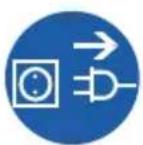
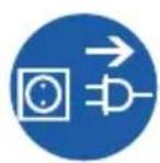
Before carrying out any work on the machine, disconnect the plug from the socket.

Pressure bottle to be secured by chain


Warning against dangerous voltage


Risk of explosion

Caution - hot surface!


Warning against toxic fumes! Not to be used in enclosed spaces

Protect against humidity Never expose tool to rain.

Prohibition for persons with a pacemaker!

Keep distance of persons Observe to keep out of dangerous zone
3-phase transformer
 | MIG (welding, metal-inert-gas) MAG (welding, metal-active-gas) Flux ( Cored wire welding) |
 | WIG (tungsten inert gas welding) |
 | MMA (electrode welding) |
 | Suitable for welding with an increased electric risk. |
 | 3-phase alternating current with rated frequency of 50/60 Hz |
 | Any damaged or disposed electric or electronic devices must be delivered to appropriate collection centres. |
 | Protect against humidity |
 | This side up |
Requirements for operating staff
The operating staff must carefully read the Operating Instructions before using the appliance.
Qualification: Apart from the detailed instructions by a professional, no special qualification is necessary for appliance using.
Minimum age: Persons over 16 years of age can only work on the appliance. An exception includes youngsters trained in order to reach knowledge under supervision of the trainer during occupational education. Training: Using the appliance only requires corresponding training by a professional or the Operating Instructions. No special training is necessary.
Emergency procedure
Conduct a first-aid procedure adequate to the injury and summon qualified medical attendance as quickly as possible. Protect the injured person from further harm and calm them down. For the sake of eventual accident, in accordance with DIN 13164, a workplace has to be fitted with a first-aid kit. It is essential to replace any used material in the first-aid kit immediately after it has been used.
If you seek help, state the following pieces of information:
- Accident site
- Accident type
- Number of injured persons
- Injury type(s)
Maintenance
Before carrying out any work on the machine, disconnect the plug from the socket.
Prior to every use, visually check the machine to rule out any defects, in particular on the power cable and the plug. The machine must not be used under any circumstances if the machine or the safety devices are damaged. If the device is defective, the repair has to be made exclusively by the customer service.
Use only original accessories and original spare parts.
Never clean the machine and its components with solvents, flammable or toxic liquids. Us only a damp cloth making. Use a soft brush to remove the deposited dust from the ventilation hole and moving parts after each use. All moving metal parts, e.g. wheels and the side cover, to be regularly lubricated with oil.
Only a regularly maintained and treated appliance can serve as a satisfactory aid. Insufficient maintenance and care can lead to unforeseen accidents and injuries. If necessary, a list of spare parts can be found at www.guede.com.
Guarantee
Warranty period of 12 months applies to commercial use and 24 months applies to private use and commences on the day of purchase of the device.
The guarantee solely covers inadequacies caused by material defect or manufacturing defect. Original payment voucher with the sales date needs to be submitted for any claim in the guarantee period.
The guarantee does not cover any unauthorised use such as appliance overloading, use of violence, damage as a result of any unauthorised interference or caused by foreign items. Failing to follow the operating and assembly instructions and common wear are also not included in the guarantee.
Service
Do you have any technical questions? Any claim? Do you need any spare parts or operating instructions? We will quickly help you and without needles bureaucracy at our web pages at www.guede.com in the Servicing part. Please help us be able to help you. In order to identify your device in case of claim we need the serial No., product No. and year of production. All this data can be found on the type label. Please enter it here for future reference:
Serial No.:
Art. No:
Year of production:
Disposal
Waste batteries and waste electrical and electronic equipment must not be disposed of together with household waste. Waste batteries and waste electrical and electronic equipment must be collected and disposed of separately. Remove used batteries, accumulators and lamps from the devices before disposing of them. Ask the local authorities or your retailer about recycling centres and collection points. Depending on local regulations, retailers may be obliged to take back used batteries and waste electrical and electronic equipment free of charge. Help reduce the demand for raw materials by reusing and recycling your used batteries and waste electrical and electronic equipment. Waste batteries (especially lithium-ion batteries) and waste electrical and electronic equipment contain valuable, recyclable materials that can have a negative impact on the environment and your health if not disposed of in an environmentally friendly manner. Delete any personal data on your old device before disposing of it.
Failure removal
| Failures Causes Removal | ||
| Wire not feeding despite wire feed pulley turning. | Dirty current nozzle Clean | |
| Coil carrier clutch set too tight. Loosen | ||
| Damaged hose bundle Check the wire guide housing | ||
| Too low clamping pressure of the wire feed pulley | Increase the clamping pressure | |
| Interrupted or disruptive wire supply | Damaged current nozzle Replace | |
| Burnt current nozzle Replace | ||
| Dirty driving gear nozzle Clean | ||
| Cut on worn driving gear Replace | ||
| Electric arc turned off Poor contact between earth pliers and the respective part | Tighten the pliers and check themRemove paint and rust | |
| Porous welded joint Wrong distance of inclination of the hose bundle | Distance between the hose bundle and the respective part must be 5-10 mm. Inclination must not be lower than 60 with respect to the part. | |
| Welder suddenly stops working after longer operation | Welder has overheated due to too long use and the thermal protection has activated | Let the welder cool down |
Attention - surface chaude!