
PVXp Sub - Subwoofer PEAVEY - Free user manual and instructions
Find the device manual for free PVXp Sub PEAVEY in PDF.

| Product Type | Active subwoofer |
| Brand and Model | Peavey PVXp Sub |
| Dimensions (operating) | 616 × 425 × 584 mm (24.25 × 16.75 × 23.00 inches) |
| Dimensions (shipping) | 687 × 425 × 616 mm (27.06 × 16.75 × 24.25 inches) |
| Net Weight | 34.5 kg (76 lbs) |
| Power Supply | 100-120 V~ or 220-240 V~, 50-60 Hz, 160 W nominal |
| Amplifier Power | 800 W peak, 470 W continuous at 4 Ω |
| Speaker | 15" (380 mm), voice coil 3" (75 mm) |
| Frequency Response | 43 Hz - 180 Hz (-10 dB), 48 Hz - 138 Hz (-6 dB) |
| Maximum SPL | 123 dB SPL continuous, 127 dB SPL peak (at 1 m) |
| Input | 1x female XLR / TRS 6.35 mm combo (balanced or unbalanced) |
| Outputs | 2x high-pass XLR (adjustable filter 90-180 Hz), 1x full-range XLR |
| Controls | Level, crossover frequency, Kosmos C, polarity, ground lift |
| Crossover Filter | Low-pass 24 dB/octave, high-pass 18 dB/octave, adjustable from 90 to 180 Hz |
| Protection | DDT compression (progressive limiter), thermal protection, 5A circuit breaker |
| Enclosure Material | 15 mm MDF, black acrylic paint finish, perforated steel grille |
| Included Accessories | IEC power cord, M20 threaded pole mount for satellite speaker |
| Maintenance | Disconnect before cleaning; use a dry cloth; no solvents |
| Safety | Do not open; refer repairs to an authorized service center; mandatory grounding |
Frequently Asked Questions - PVXp Sub PEAVEY
User questions about PVXp Sub PEAVEY
0 question about this device. Answer the ones you know or ask your own.
Ask a new question about this device
Download the instructions for your Subwoofer in PDF format for free! Find your manual PVXp Sub - PEAVEY and take your electronic device back in hand. On this page are published all the documents necessary for the use of your device. PVXp Sub by PEAVEY.
USER MANUAL PVXp Sub PEAVEY
PVX™p Sub
Compact Vented Powered Subwoofer System
natural_image
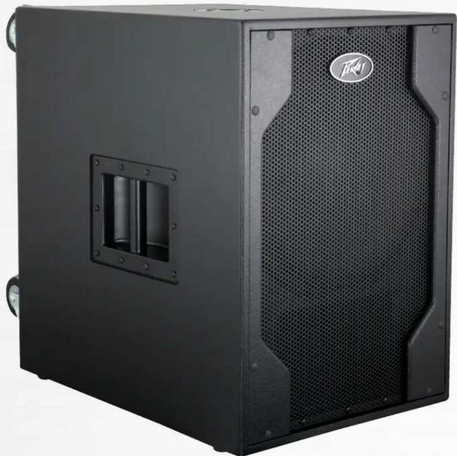
Black audio amplifier box with mesh grille and speaker grille (no visible text or symbols)Operating Manual

Intended to alert the user to the presence of uninsulated “dangerous voltage” within the product’s enclosure that may be of sufficient magnitude to constitute a risk of electric shock to persons.
Intended to alert the user of the presence of important operating and maintenance (servicing) instructions in the literature accompanying the product.
CAUTION: Risk of electrical shock — DO NOT OPEN!
CAUTION: To reduce the risk of electric shock, do not remove cover. No user serviceable parts inside. Refer servicing to qualified service personnel.
WARNING: To prevent electrical shock or fire hazard, this apparatus should not be exposed to rain or moisture, and objects filled with liquids, such as vases, should not be placed on this apparatus. Before using this apparatus, read the operating guide for further warnings.

Protective earthing terminal. The apparatus should be connected to a mains socket outlet with a protective earthing connection.

IMPORTANT SAFETY INSTRUCTIONS
WARNING: When using electrical products, basic cautions should always be followed, including the following:
-
Read these instructions.
-
Keep these instructions.
-
Heed all warnings.
-
Follow all instructions.
-
Do not use this apparatus near water.
-
Clean only with a dry cloth.
-
Do not block any of the ventilation openings. Install in accordance with manufacturer's instructions.
-
Do not install near any heat sources such as radiators, heat registers, stoves or other apparatus (including amplifiers) that produce heat.
-
Do not defeat the safety purpose of the polarized or grounding-type plug. A polarized plug has two blades with one wider than the other. A grounding type plug has two blades and a third grounding plug. The wide blade or third prong is provided for your safety. If the provided plug does not fit into your outlet, consult an electrician for replacement of the obsolete outlet.
-
Protect the power cord from being walked on or pinched, particularly at plugs, convenience receptacles, and the point they exit from the apparatus.
-
Only use attachments/accessories provided by the manufacturer.
-
Use only with a cart, stand, tripod, bracket, or table specified by the manufacturer, or sold with the apparatus. When a cart is used, use caution when moving the cart/apparatus combination to avoid injury from tip-over.
-
Unplug this apparatus during lightning storms or when unused for long periods of time.
-
Refer all servicing to qualified service personnel. Servicing is required when the apparatus has been damaged in any way, such as power-supply cord or plug is damaged, liquid has been spilled or objects have fallen into the apparatus, the apparatus has been exposed to rain or moisture, does not operate normally, or has been dropped.
-
Never break off the ground pin. Write for our free booklet "Shock Hazard and Grounding." Connect only to a power supply of the type marked on the unit adjacent to the power supply cord.
-
If this product is to be mounted in an equipment rack, rear support should be provided.
-
Note for UK only: If the colors of the wires in the mains lead of this unit do not correspond with the terminals in your plug, proceed as follows: a) The wire that is colored green and yellow must be connected to the terminal that is marked by the letter E, the earth symbol, colored green or colored green and yellow. b) The wire that is colored blue must be connected to the terminal that is marked with the letter N or the color black. c) The wire that is colored brown must be connected to the terminal that is marked with the letter L or the color red.
-
This electrical apparatus should not be exposed to dripping or splashing and care should be taken not to place objects containing liquids, such as vases, upon the apparatus.
-
The on/off switch in this unit does not break both sides of the primary mains. Hazardous energy can be present inside the chassis when the on/off switch is in the off position. The mains plug or appliance coupler is used as the disconnect device, the disconnect device shall remain readily operable.
-
Exposure to extremely high noise levels may cause a permanent hearing loss. Individuals vary considerably in susceptibility to noise-induced hearing loss, but nearly everyone will lose some hearing if exposed to sufficiently intense noise for a sufficient time. The U.S. Government's Occupational Safety and Health Administration (OSHA) has specified the following permissible noise level exposures:
Duration Per Day In Hours Sound Level dBA, Slow Response
| 8 90 | |
| 6 92 | |
| 4 95 | |
| 3 97 | |
| 2 100 | |
| 1 1/2 102 | |
| 1 105 | |
| 1/2 | 110 |
| 1/4 or less 115 |
According to OSHA, any exposure in excess of the above permissible limits could result in some hearing loss. Earplugs or protectors to the ear canals or over the ears must be worn when operating this amplification system in order to prevent a permanent hearing loss, if exposure is in excess of the limits as set forth above. To ensure against potentially dangerous exposure to high sound pressure levels, it is recommended that all persons exposed to equipment capable of producing high sound pressure levels such as this amplification system be protected by hearing protectors while this unit is in operation.
SAVE THESE INSTRUCTIONS!
a) The wire that is colored green and yellow must be connected to the terminal that is marked by the letter E, the earth symbol, colored green or colored green and yellow.
b) The wire that is colored blue must be connected to the terminal that is marked with the letter N or the color black.
c) The wire that is colored brown must be connected to the terminal that is marked with the letter L or the color red.
Logo referenced in Directive 2002/96/EC Annex IV(OJ(L)37/38,13.02.03 and defined in EN 50419: 2005
The bar is the symbol for marking of new waste and is applied only to equipment manufactured after 13 August 2005
Correct Disposal of this product. This marking indicates that this product should not be disposed with other house hold wastes throughout the EU. To prevent possible harm to the environment or human health from uncontrolled waste disposal, recycle it responsibly to promote the sustainable reuse of material resources. To return your used device, please use the return and collection systems, or contact the retailer where the product was purchased. They can take this product for environmental safe recycling.

FCC Compliancy Statement
This equipment has been tested and found to comply with the limits for a Class A digital device, pursuant to Part 15 of the FCC rules. These limits are designed to provide reasonable protection against harmful interference when the equipment is operated in a commercial environment. This equipment generates, uses and can radiate radio frequency energy and, if not installed and used in accordance with the instruction manual, may cause harmful interference to radio communications. Operation of this equipment in a residential area is likely to cause harmful interference in which case the user will be required to correct the interference at his own expense.
Warning: Changes or modifications to the equipment not approved by Peavey Electronics Corp. can void the user's authority to use the equipment.
CAN ICES-3(A)/NMB/3(A)

Peavey Electronics Corporation • 5022 Hartley Peavey Drive • Meridian, MS • 39305
(601) 483-5365 • FAX (601) 486-1278 • www.peavey.com
Features and specifications are subject to change without notice.
ENGLISH
PVX™p Sub
Thank you for purchasing the powered Peavey® PVX™ p Sub. The PVXp Sub features an ultra-reliable power section that provides a total of 800 watts of peak available power with DDT™ compression. This powered enclosure also features a 15" heavy-duty woofer with a 3" voice coil. The PVXp Sub provides a balanced input via a combination jack that accepts balanced TRS 1/4" input as well as a balanced XLR input. There are two balanced thru high pass XLR outputs, and a Full-Range XLR output. There is an adjustable Level control, as well as a combination LED indicator, that illuminates when power is on and when the "soft-limiting" DDT circuit is activated.
Features
- Vented bass powered subwoofer enclosure
- 800 watts peak available power
- 15" heavy-duty woofer
- Power Amp has forced air cooling for maximum reliability
- Internal line level low-pass/high-pass crossover network
- Fully adjustable Kosmos® C for increased bass impact
- XLR/1/4" combo jack input
- Two high-pass XLR outputs, and one full-range thru XLR output
- Polarity switch for polarity reversal of subwoofer
- Ground lift for lifting cable shield from ground
• Large heavy-duty locking casters with damped bearings
• Full-coverage heavy-duty perforated steel grill - Steel handles
- Compact dimensions for a 15" woofer based sub
- Threaded pole mount with speaker pole included
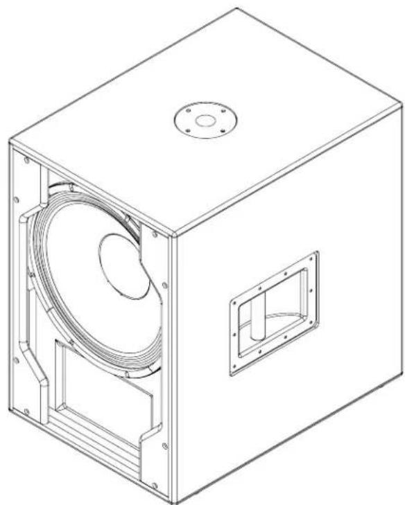
DESCRIPTION
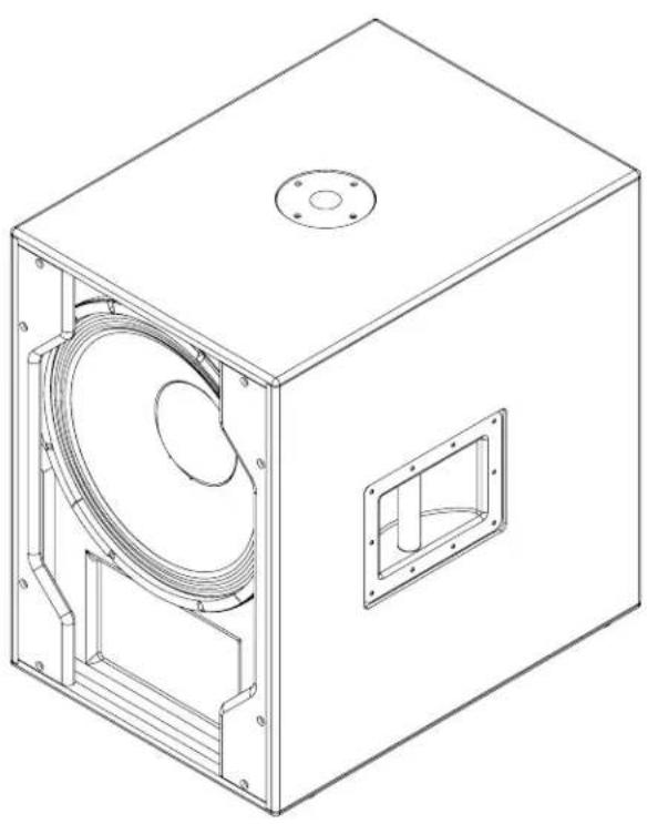
The Peavey® PVXp Sub is a compact, vented, powered subwoofer system utilizing a 15" heavy-duty woofer, coupled to a power amplifier, with 800 watts peak available power. The full-length black perforated steel grille provides protection and a professional appearance, along with the sturdy steel handles and heavy-duty 4" tall casters for transport.
Internal line-level crossover with two high-pass outputs, independently electrically buffered; and one full-range thru output, also electrically buffered.
Peavey's exclusive Kosmos® C bass enhancer for extra bass punch from very low frequency program material is incorporated for maximum versatility.
A threaded pole-mount system provides a sturdy and stable platform to mount a suitably equipped speaker system above the sub woofer. The PVXp two-way powered speaker series are an excellent partner for the PVXp Sub.
The PVXp Sub speaker system power amplifier providing the power is a low-distortion ultra-reliable fan-cooled unit providing a total of 800W peak available power for the system. The power supply for the power amp is a switch-mode type for low weight and high efficiency. The amplifier features our DDT compression, which virtually eliminates audible power amplifier clipping. Cooling is provided via a low-noise fan, for reliable operation under any conditions.
Input is via a combo female XLR and 1/4" TRS phone jack with balanced input to the preamp/EQ electronics, and a level control.
An independent pair of High-Pass Outputs provides a buffered and balanced output signal for a pair of satellite speakers to carry the high range of the music, via a pair of male XLR jacks.
A Full-Range Thru output has a male XLR connector. These outputs allow linking of additional speaker systems, or feed of the signal to other devices, etc. Included in the input panel is a bay for optional function modules, such as a Wireless Receiver, Digital Audio Input or a 10-band EQ, etc.
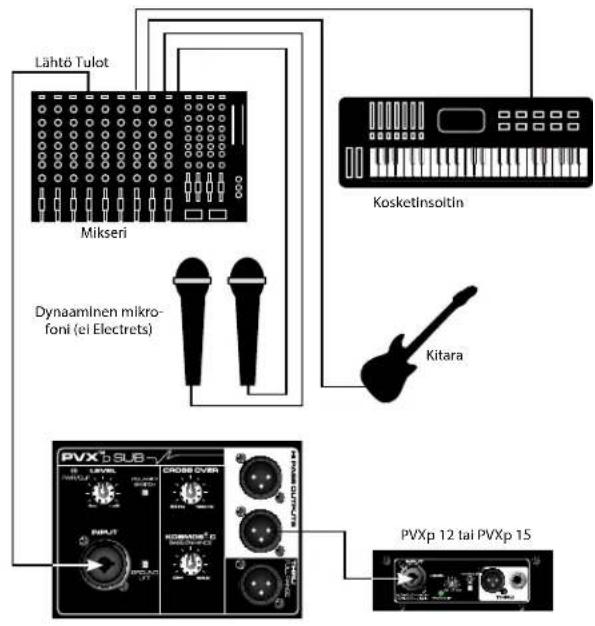
APPLICATIONS
The Peavey PVX™ p Sub has a variety of applications, such as extending the bass performance of smaller full-range speaker systems for sound reinforcement, public address, side fill system, karaoke or musical playback.
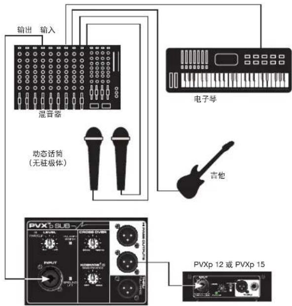
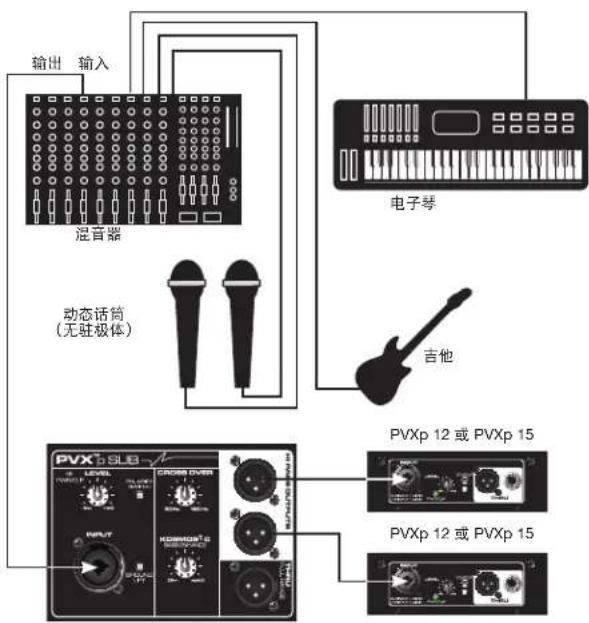
A typical signal source for the line-level inputs of the Peavey PVXp Sub would be a sound reinforcement mixing console (mixer) or the output from a CD player, MP3 player or tape deck. The high-pass filtered signal from the PVXp Sub would then be sent to a full-range powered speaker system, easing the burden of deep bass from this speaker system.
REAR PANEL BOTTOM
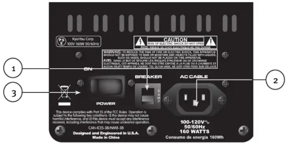

CIRCUIT BREAKER (1)
The unit is AC power line protected from overloads and fault conditions with a 5 amp circuit breaker. This breaker should not trip unless there is a fault in the amplifier circuitry or an abnormal operating condition, which causes excessive mains current to flow. If the breaker trips, set the Power switch (3) to OFF, and after waiting a brief period of time for the breaker to cool, reset the breaker.
If the circuit breaker trips, the center button will pop outward approximately 1/4", and can be reset by pushing upward and inward. Under normal (not tripped) conditions, the center button is relatively flat.
If the unit continues to trip the breaker, or trips it immediately after being reset, do not keep resetting it, the system should be taken to a qualified Peavey Service Center for repair.

IEC POWER CORD CONNECTION (2)
This receptacle is for the IEC line cord (supplied) that provides AC power to the unit. It is very important that you ensure the PVXp Sub has the proper AC line voltage supplied. You can find the proper voltage for your PVXp Sub printed next to the IEC line (power) cord on the rear panel of the unit.

Please read this guide carefully to ensure your personal safety as well as the safety of your equipment. Never break off the ground pin on any equipment. It is provided for your safety. If the outlet used does not have a ground pin, a suitable grounding adapter should be used and the third wire should be grounded properly. To prevent the risk of shock or fire hazard, always be sure that the mixer and all other associated equipment are properly grounded.
REAR PANEL TOP
ACCESS PANEL FOR OPTIONAL EXPANSION MODULE
This panel is to be removed ONLY when installing one of a variety of Optional Expansion Modules that will be available soon for the PVXp Sub.
These Optional Expansion Modules will either work in conjunction with the input already present on the PVXp Sub, or provide an in-line function for the input, such as a 10-band EQ, etc. Check with your Peavey ^® dealer for availability and price.
If you are not installing such an Optional Expansion Module, then do not remove this cover, instructions for installing an Optional Expansion Module will come with each Expansion Module and will be specific for that Module.
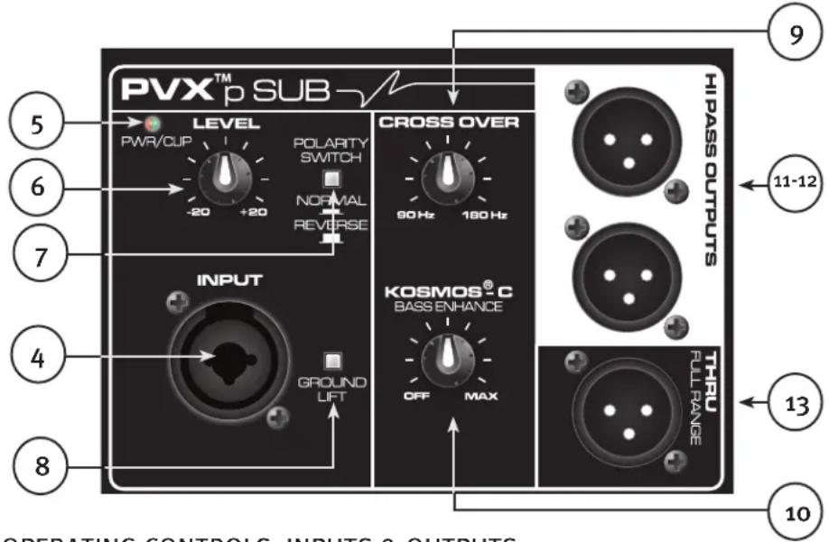
TOP – OPERATING CONTROLS, INPUTS & OUTPUTS
INPUT (4)
The line-level input is of the medium impedance balanced type. The jack is a combo female XLR and 1/4" TRS connector.
LED (5)
Illuminates GREEN when the power switch is on and power is present
It turns RED when the power amp engages the DDT ^™ “soft limiting” circuitry. Occasional flashing is acceptable, but not a constant illumination, or distortion will be excessive.
There is also an LED visible on the front baffle of the Sub that illuminates BLUE when power is applied, and turns RED when the power amp engages the DDT “soft limiting” circuitry.
LEVEL (6)
Controls the gain or output level of the input signal. It is used to directly set the system output level for a given input signal.
Normal usage is with the knob set to half-way, this is then equivalent in gain to a typical power amp input.
POLARITY SWITCH (7)
Provides either o degrees or 180 degrees sub woofer polarity
This switch is used on conjunction with the Crossover Frequency Control (9) to provide for the best match between the Subwoofer output and the satellite speaker output in the crossover region.
GROUND LIFT SWITCH (8)
Provided for lifting cable shield from chassis ground, to break potential ground loops and reduce hum.
CROSSOVER FREQUENCY CONTROL (9)
Varies the crossover frequency between the Subwoofer and the High Pass Outputs sent to the satellite/s speaker/s (11 & 12). Varies the electrical crossover frequency from 90 Hz to 180 Hz.
CAUTION! SETTING THIS CONTROL TOO LOW MAY ALLOW THE SATELLITE SPEAKER TO BE OVERLOADED BY DEEP BASS!
Setting the control lower DOES NOT increase the deep bass output of the PVX ^™ p Sub, a middle (12 o'clock) to higher setting works best for most speakers.
KOSMOS® C BASS ENHANCEMENT (10)
Provides the capability to add bass harmonics to enhance the perception of deep bass in the program material without overloading the Subwoofer speaker.
This control is best used in moderation, and turning it full up can cause the program material to sound distorted or unnatural.
HIGH PASS OUTPUTS (11 & 12)
These outputs provide a high-pass filtered signal to be fed to a full-range powered speaker system, such as the PVXp 10, PVXp 12 or PVXp 15. Other full-range powered speakers can be used, and full-range passive speakers can be used in conjunction with a suitable power amp to drive them.
These outputs are electronically buffered and isolated from the input and from each other, and their level is not affected by the PVXp Sub Level control (6).
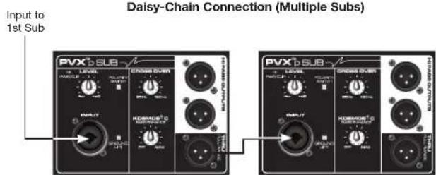
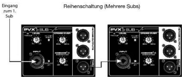
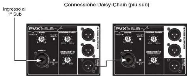
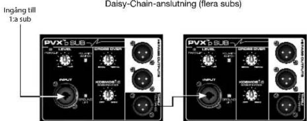
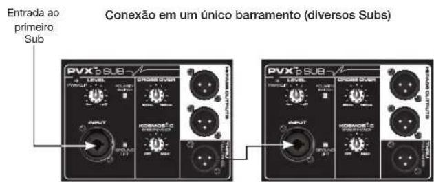
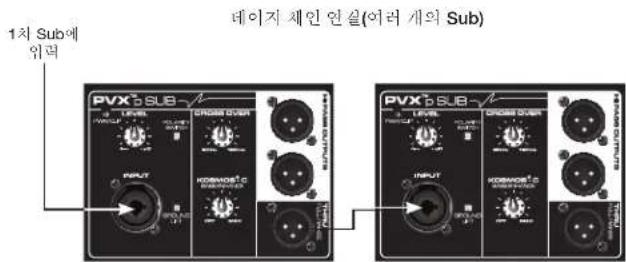
THRU FULL RANGE OUTPUT (13)
This output provides a full-range signal to be sent to any other device that requires a full-range signal, such as another PVXp Sub, or some other line level audio device. This output is electronically buffered and isolated from the input and from the other outputs.
OPERATING INSTRUCTIONS
CAUTIONS
The unit must be disconnected from the AC power source before any work is done on it. Refer all servicing to qualified service personnel.
The back plate can become hot to the touch. Do not block or cover the fan or the exhaust louvers from ventilation. There must be a minimum of 4" of space behind the fan. Do not allow the airflow to be become blocked by objects such as curtains or drapes, thermal building insulation, etc. It is recommended that the rear of the PVXp Sub not be placed in a closed space or a space that has no fresh, cool airflow.
DO NOT connect the inputs of the PVXp Sub to the output of a power amplifier. The inputs are meant to be driven from a line-level strength signal.
DO NOT remove the protective metal grilles.
WARNING! The PVXp Sub is very efficient and powerful! This sound system can permanently damage hearing! Use extreme care setting the overall maximum volume!
The apparent sound level of the PVX ^™ p Sub can be deceiving due to its clear, clean sound output and lack of high frequencies. The lack of distortion or obvious distress can make the sound level seem much lower than it actually is. This system is capable of SPL in excess of 127 dB at 1 M from the speaker!
PLACING A SATELLITE SPEAKER SYSTEM ON TOP OF THE PVX™P SUB
The PVXp Sub has a threaded pole mount built-in to the top of the unit, and this is designed to mate with an M20 threaded pole of approximately 32" in length or less. This pole is specifically designed to be used with the following speaker systems:
Peavey PVXp 10
Peavey PVXp 12
Peavey PVXp 15
Do not place a taller/larger or heavier speaker system than the PVXp 15 on this pole, or it may be unsafe due to the potential to tip over.
The PVXp Sub must be placed on firm and level ground, in order for the pole mounted speaker to be safe from tipping.
When installing or de-installing the speaker on the pole, it is a good practice to have a helper, if possible. It can be hard to “thread the needle” and mate the pole cup to the Subwoofer pole while holding the speaker system at arm’s length.
When using the PVXp Sub and pole outdoors, never attach banners or flags to the pole or the pole mounted speaker system, strong winds may cause the speaker to blow over. If there is a possibility of strong windy conditions, then it may be prudent to consider removing the speaker from the pole to prevent the PVXp Sub and pole mounted speaker system from being blown over.
CONNECTING AC POWER TO THE PVXP SUB
The PVXp Sub comes with a 6-foot IEC connection AC power cord. If you are using an extension cord or power strip with this powered speaker, make sure it is of good quality and of a sufficient current capacity to maintain safety and maximize the power output capability of the PVXp Sub. For maximum undistorted output, do not connect any other device to the same extension cord that the PVXp Sub is connected to. Do not exceed the rated current capacity of the extension cord with the sum total of all units connected to it.
When first plugging in the PVXp Sub AC cord, make sure the power switch is in the Off position, and then turn it On only after connecting the power cord. Built-in muting will engage, when the proper sequence of steps is taken.
SPECIAL NOTE FOR PERMANENT INSTALLATION
When installing the PVXp Sub, AC power runs will be used and a certified electrician should be consulted, to be sure that all AC wiring complies with local codes and regulations. It is also advisable to use a cable clip properly affixed to the cabinet to strain relief the IEC power cord connected to the amplifier module at (2) so the power cord cannot be pulled out or vibrate loose.
CONNECTING A SIGNAL TO THE PVXP SUB
There are a variety of ways to input a signal into the PVXp Sub.
The input (4) provides a balanced line-level input, allowing the use of a 1/4" TRS (ring-tip-sleeve) type phone plug or a male XLR plug. Of course, an unbalanced 1/4" phone plug can be used as well, but it will not have the benefit of the balanced connections rejection of outside interference, such as hum and RFI.
Do not connect cables to the jacks while the unit is ON and the Level knob is turned up! While a standard single-ended 1/4" phone plug-equipped cable will work well and the balanced input circuitry will provide some interference rejection, a balanced cable using either the balanced TRS 1/4" phone plug or the XLR plug will provide superior interference rejection and performance.
Sometimes, with difficult interference problems, it will be helpful to lift the shield ground (Pin #1 of an XLR) of a balanced cable at the PVX™p Sub end. This can be done quite easily, by activating the Ground Lift switch (10) built into the PVXp Sub. Check any input changes carefully, always turning the Level control down before plugging and unplugging cables, or lifting the ground.
Use of high quality, premium cables is recommended for the PVX™p Sub, as these usually have better shielding and materials and will provide greater long-term reliability. The best option is a shielded balanced cable no longer than necessary to reach the PVXp Sub. It is usually a good idea to leave some slack at the input to the PVXp Sub and also to tape the cables down or run them under a cable guard, to avoid anyone tripping over them or pulling the PVXp Sub over when it is holding a speaker on top of it's pole.
LEVEL CONTROL ADJUSTMENT
The PVXp Sub is equipped with a Level control (6) on the input to facilitate use in many different applications. With the Level control adjusted fully clockwise, gain is at maximum and the input sensitivity is 0.24 V RMS for full-rated output.
It is recommended that the PVXp Sub Level control be set close to 12 o'clock position, or o dB preamp gain. At this setting, the input sensitivity is approximately 2.4 volts RMS for full-rated output. The PVXp Sub will now more closely match a typical power amp input.
If the mixing board indicates clipping of its output signals, then all of the PVXp Sub power capability is not being utilized cleanly. Clipping the signal before it gets to the PVXp Sub is not optimal. Reduce the mixer output level and turn up the Level control on the PVXp Sub.
The amplifier in the PVXp Sub is equipped with DDT ^™ and the LED indicator will show when PVXp Sub DDT has engaged. If the sound seems heavily compressed, check these indicators; if it is blinking RED more than occasionally, then the drive level from the mixer (or the Level control on the PVXp Sub) needs to be reduced.
When first turning on the sound system, switch on all upstream electronics first, then the PVXp Sub with its Level control fully counterclockwise (all the way down). Begin checking levels with the mixer output level controls all the way down, and bring them up slowly with the PVXp Sub Level control set to the desired setting (one-half way up recommended to start).
It is not good practice to turn the Level control on the PVXp Sub all the way up and then try to control level only from the mixer, this approach would tend to pick up excess noise. Best practice would be to run a “hot” signal from the mixer down the cable to the PVXp Sub, and then turn the PVXp Sub Level control up only as much as necessary to reach full desired output. With this approach, it is necessary to verify the mixer output is not clipping.
CABLES FROM THE HIGH PASS OUTPUTS (11 & 12)
The preferred method of connecting a full-range satellite speaker system to the PVXp Sub's High Pass Outputs (11 & 12), is to use a balanced XLR cable no longer than necessary to comfortably reach the satellite speaker system.
If the satellite speaker is on top of a pole above the PVXp Sub, then a 6 foot cable will be plenty long. A 10, or 20 foot cable could also be used, but cables longer than that will only allow more interference pickup, and start to lose high-frequency information. Use of high quality, premium cables is recommended for the PVXp Sub, as these usually have better shielding and materials and will provide greater long-term reliability. . It is usually a good idea to leave some slack at the output of the PVXp Sub, and also to tape the cables down or run them under a cable guard to avoid anyone tripping over them or pulling the PVXp Sub over when it is holding a speaker on top of it's pole.
RECOMMENDED SETTINGS FOR USE OF THE PVXP SUB WITH THE PVXP SERIES POWERED SPEAKERS
The ideal location for placement of the powered PVX ^™ p series full-range speakers is on top of the PVXp Sub pole. In that close proximity, the following settings will provide the best results in the crossover region, and for tonal balance.
Note that the XLR outputs (11 & 12), have been padded 12 dB to allow the XLR inputs on the PVXp 12 and PVXp 15 to be used. Normally, these are considered the mic level inputs, but with the PVXp Sub outputs padded, the usage of the XLR inputs on the PVXp powered speakers is possible.
PVXp 10
Polarity Switch on Sub (7): Normal or IN
Crossover Frequency Control (9): From 12 o'clock to full clockwise. This represents a range from approximately 110 Hz to 160 Hz for the crossover point. Recommended optimal setting is full clockwise position.
Level Controls (6): PVXp™ Sub Level control at 12 o'clock (o dB), PVXp10 Level control at 12 o'clock
PVXP 12
Polarity Switch on Sub (7): Normal or IN
Crossover Frequency Control (9): From 12 o'clock to full clockwise. This represents a range from approximately 110 Hz to 160 Hz for the crossover point.
Recommended optimal setting is set to two tics past 12 o'clock.
Level Controls (6): PVXp sub Level control at 12 o'clock (o dB), PVXp 12 Level control at -2 tics before 12 o'clock
PVXp 15
Polarity Switch on Sub (7): Normal or IN
Crossover Frequency Control (9): From 12 o'clock to full clockwise. This represents a range from approximately 110 Hz to 160 Hz for the crossover point.
Recommended optimal setting is set to 12 o'clock.
Level Controls (6): PVXp Sub Level control at 12 o'clock (o dB), PVXp 12 Level control at -2 tics before 12 o'clock
CAUTION! SETTING THE CROSSOVER FREQUENCY CONTROL TOO LOW MAY ALLOW THE SATELLITE SPEAKER TO BE OVERLOADED BY DEEP BASS AT HIGH SPL!
Setting the control lower DOES NOT increase the deep bass output of the PVXp Sub, a middle (12 o'clock) to higher setting works best for most speakers.
If the PVXp series speakers are not set on top of the Subwoofer on the pole, then the polarity switch settings may need to be different than what is provided here. The Crossover Frequency Control may need to be set to a lower point in order for the Subwoofer and the satellites to sum well through the crossover region. The settings outlined above will work the best when the satellite speaker and the Subwoofer are closer together, and essentially the same distance from the audience.
SETTING THE PVXp SUB CONTROLS FOR USE WITH OTHER SATELLITE SPEAKERS
Crossover Frequency Control (9): In general, for smaller full-range speakers to be used as satellites, set the Crossover Frequency Control (9) to a higher frequency setting. For larger full-range speakers, set the Crossover Frequency Control (9) to a lower frequency setting. Setting the Crossover Frequency Control very much below the 12 o'clock position will not be needed most of the time, as a crossover frequency below 100 Hz is not going to allow the PVXp Sub and the satellite speaker to add together very well in the crossover region.
Polarity Switch (7): Try changing the Polarity Switch setting back and forth at each selected crossover frequency, so as to determine which switch position provides the most bass output in the crossover region
Level Controls (6): Start with the PVXp Sub Level control in the 12 o'clock position, and adjust the satellite speaker system to match it's level. Note that if the Subwoofer can be heard as a distinctly separate sound source, then it is probably set too high in level.
SETTING THE KOSMOS® C BASS ENHANCE CONTROL (10)
The Kosmos® C Bass Enhance control can add apparent bass extension and output to the reproduced sound, especially when the program material has significant content below the PVXp Sub's cut-off frequency.
When appropriate, judicious use can enhance the enjoyment of the music, and add punch and boom to the mix. However, setting the control to higher than optimal level can result in a perception of noticeable distortion or less clear bass sounds. Seldom will it be helpful to turn the control all the way up.
Typical use will involve a setting of the control knob somewhere between Off (full counter clockwise) and 12 o'clock (half-way up). Then the added effect is more subtle and less intrusive during certain moments in the music, while still providing a welcome enhancement of the overall sound.
Note that at extreme full clockwise settings, the effective gain of the Subwoofer is increased, so if it was on the verge of clipping before, turning the Bass Enhance Control way up may cause it to go into clipping.
DISCONNECTING AC POWER TO THE PVX™P SUB
We recommend that the Power switch (3) be used to turn the unit off first, and then the AC power cord can be removed, this minimizes stress to the power amplifiers and the transducers from turn-off transients. The power switch has an arc suppression capacitor to help during turn-off, and tends to make a clean disconnect from the AC power, while the power cord IEC connector can make intermittent contact before finally becoming fully disconnected, e.g., as when wiggling the cord.
TROUBLESHOOTING
NO OUTPUT AT ALL
First, make sure the unit has AC power and is turned ON. Make sure the LED on the power amp module is illuminated.
If not, make certain the ON/OFF switch (3) is in the ON position and check the IEC power cord connection (2) by ensuring it is fully engaged and seated. Make certain the AC line cord is plugged into a working AC outlet.
Finally, check the breaker (1). (See the Rear Panel: Breaker section, for safety instructions.)
Once assured your unit is getting AC power, check that the PVX ^™ p Sub is getting a signal. Temporarily disconnect the cable running to its inputs and connect it to some other device capable of reproducing the signal (i.e., a power amp and speaker). If this produces a signal, make sure that all Level controls being used have been turned up to a satisfactory level (one-third to halfway).
If the PVXp Sub has been subjected to direct sunlight or excessive heat, the built-in thermal protection may have been triggered. If so, turn off the PVXp Sub and let it cool for a sufficient amount of time.
If there is still no output, contact your authorized Peavey dealer or the Peavey International Service Center.
HUM OR BUZZ
If the PVXp Sub is producing a hum or buzz, this can be AC outlet related. Try plugging the PVXp Sub into a different AC outlet. Sometimes, if a different circuit (breaker) is used for the mixer and for the PVXp Sub, it can cause hum problems. Unless it is not practical, it is best to use the same wall outlet (breaker) to supply power to both the mixer and the powered speaker.
Ensure that shielded cables have been used to route the signal to the PVXp Sub's input. If speaker cables with 1/4" plugs are used as input cables instead of shielded cables, they will be prone to hum or buzz.
Hum may be ground loop related. It may be helpful to lift the shield ground (Pin #1) on a balanced cable at the PVXp Sub end. This is done quite easily by activating the Ground Lift switch (10) built-in to the PVXp Sub. Check any input changes carefully by first turning down the Level control, before plugging and unplugging cables, or lifting the shield ground at the Sub.
Check to make sure light dimmers are not on the same circuit as the PVXp Sub, the mixer or any source devices. If light dimmers are used, then it may be necessary to turn them full ON or full OFF to eliminate or reduce hum. This is a typical AC wiring/light dimmer interference problem, not a design flaw of the PVXp Sub.
The third wire (ground plug) on the AC plug should NEVER be removed or broken off, as this is a potential safety hazard.
DISTORTED OR FUZZY SOUND
First, ensure the mixer (signal source) is not clipping or being overdriven. Make sure the Level (6) control on the PVXp Sub has not been set too low. Check that the input plug is fully seated in the input jack on the rear panel of the PVXp Sub. Ensure that a power amp has not been plugged into the input jack of the PVXp Sub. If an extension cord is being used to provide the AC power to the unit, ensure that it is of sufficient current capacity and that it is not also being used to supply power to any other device.
The PVXp Sub has a built-in bass boost to extend and smooth the natural response of the speakers in the system, so it should require little, if any, additional EQ. If excessive additional bass boost have been added externally to the PVXp Sub, it could cause premature overload at high SPL. Reduce the amount of any external (mixer, rack) EQ and see if that clears up the distortion.
Finally, realize that even though the PVXp Sub is a powerful and high output unit, it does ultimately have limits, and it may need additional powered Subwoofer units to provide enough sound output or coverage. In this case, try turning the mixer levels down a little to see if that clears things up. If, after checking all the things listed to check and anything else you can think of to check safely, and the system still exhibits problems, carefully note all conditions and check with your Peavey dealer for advice.
CARE AND MAINTENANCE
Your PVXp Sub is a sturdy and durable product and will provide years of reliable use if properly cared for. Use common sense and read the safety warnings to avoid hazardous operating conditions.
The unit must be disconnected from the AC power source before any work is done on it. Refer all servicing to qualified service personnel.
SUNLIGHT/HEAT
Avoid prolonged exposure to direct sunlight, as this may cause the unit to overheat and thermally shut off.
Excessively hot operating conditions can also cause a thermal shutdown.
Do not store in extremely hot or cold conditions or extremely high humidity. Always allow unit to come to room temperature before use.
CLEANING
Never clean the PVXp Sub while plugged in or turned ON! When the unit has been fully disconnected from AC power sources, use a dry cloth to remove soil or other dirt. Never use strong solvents on the PVXp Sub, as they could damage the cabinet. Do not allow ANY fluids to drip inside the PVXp Sub.
TOUCH-UP
For a touch-up of any damage to the black painted finish of the PVXp Sub, you can use a black spray paint such as Peavey Commercial Sound, Black Touch-Up Paint, Peavey part number 00052110. Follow the directions on the can for safety and best results.
CHECK FOR SECURE HARDWARE
After the first few months of use and periodically thereafter, check the hardware of the PVXp Sub for tightness, including the rear panel screws and the screws that hold the grille and cabinet together.
The unit is subject to a great deal of vibration, and this could cause them to loosen with use.

Features and specifications are subject to change without notice.
Peavey Electronics Corporation • 5022 Hartley Peavey Drive • Meridian • MS • 39305
(601) 483-5365 • FAX (601) 486-1278 • www.peavey.com • ©2013 • EX000178
![[143.94] 5.667 [219.66] 8.648 [219.66] 8.648 [220.14] 8.667](/content/2026/03/531500/images/c9e1d805b60c46e4cfeec69263880a5599a8dc813db50cb2d51445b8e00c734f.jpg)
![[292.10] 11.500 [212.71] 8.375](/content/2026/03/531500/images/9e358d8ea4eafcaad8ae6aab6a35399edb9ef76a99144a0ad74fad18056bfca6.jpg)
![[613.96] 24.172 [601.50] 23.681 [425.41] 16.749](/content/2026/03/531500/images/3322d7cccfe9ee6c69f3caa5cfe5200b0e27995f483f33aca1572018dc1625cc.jpg)
![[357.30] 14.067 [40.41] 1.591 [469.54] 18.486 [74.25] 2.923 [34.06] 1.341](/content/2026/03/531500/images/d466abc10343836176bc8c407b2557ff49e53714c2ae28b282235c09871261fe.jpg)
![[143.94] 5.667 [219.66] 8.648 [220.14] 8.667 [219.66] 8.648](/content/2026/03/531500/images/667fb40a6d298438ca2e6550c6436b0c329034679fb4146ad77c82e850879b1d.jpg)
natural_image
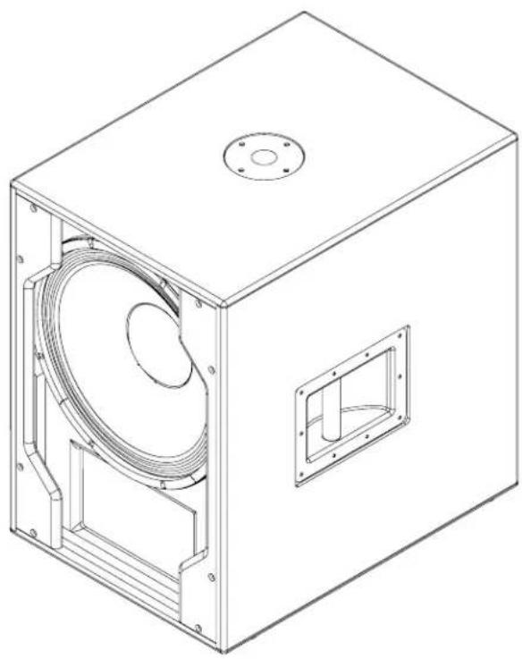
Technical line drawing of a rectangular industrial enclosure with internal components and mounting flanges (no text or symbols)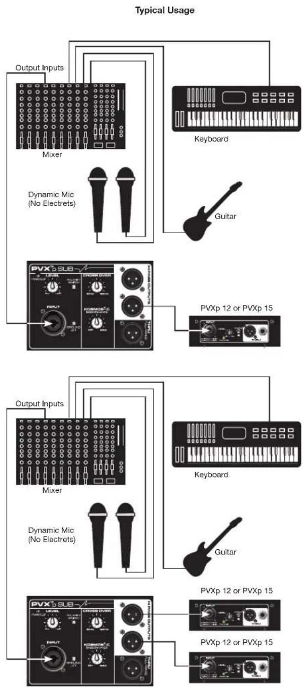
flowchart
graph TD
    A["Output Inputs"] --> B["Mixer"]
    B --> C["Dynamic Mic (No Electrets)"]
    C --> D["PVX p 12 or PVXp 15"]
    D --> E["Keyboard"]
    E --> F["Guitar"]
    F --> G["PVXp 12 or PVXp 15"]
    G --> H["Output Inputs"]
    H --> I["Mixer"]
    I --> J["Dynamic Mic (No Electrets)"]
    J --> K["PVX p 12 or PVXp 15"]
    K --> L["Guitar"]
    L --> M["PVXp 12 or PVXp 15"]
Frequency Range (-10 dB, Half Space):
43 Hz - 180 Hz*
*Crossover Control Full CW
Frequency Response, 1 Meter On-axis, Swept-sine In Anechoic Environment (-6 dB):
48 Hz - 138 Hz*
*Crossover Control Full CW
Power Amp Rating, Total Power Output:
800 watts peak available power
Continuous Power: 470 watts into 4 ohms
Electronic Input Impedance (Nominal):
Line In: 2.2 k ohms balanced (XLR or 1/4"), 10 k ohms unbalanced 1/4"
Sound Pressure Level, 1 Watt, 1 Meter In Anechoic Environment:
97 dB SPL
Maximum Sound Pressure Level (1 meter):
123 dB SPL continuous
127 dB SPL peak
Transducer Complement:
15" premium heavy-duty woofer, 3" voice coil
Box Tuning Frequency:
50 Hz
Input Connections:
One combo female XLR/ 1/4" phone jack providing balanced or unbalanced operation.
Output Connections:
Two High Pass Outputs, independently electrically buffered, with switchable output level pad.
One Full Range Thru, electrically buffered.
Controls:
Level: Provides +/- 20 dB gain adjustment
Crossover Frequency Adjust: Adjusts electrical crossover frequency from 90 Hz to 180 Hz, continuously variable.
Kosmos® C: Provides bass enhancement processing.
Polarity Switch: Provides either o degrees or 180 degrees sub woofer polarity
Ground Lift Switch: For input
Electronic Crossover
Continuously variable from 90 Hz to 180 Hz.
Low Pass slope: 24 dB/octave
High Pass Output slope: 18 dB/octave
Infrasonic Filter Slope:
36 dB/octave
Nominal Amplifier Frequency Response:
+0, -3 dB from 20 Hz to 20 kHz
Hum and Noise:
Greater than 90 dB below rated power
DDT Dynamic Range:
Greater than 21 dB
THD and IM:
Typically less than 0.5 %
Damping Factor:
Greater than 100 @ 1000 Hz, 4 Ohms
Power Requirements Of Peavey PVX™p Sub System:
Nominal 160 Watts, 100-120 VAC 50-60 Hz (Domestic)
220-240 VAC 50-60 Hz (Export)
Enclosure Materials & Finish:
Black acrylic painted enclosure with 15 mm MDF, with a full-length, black powder coated perforated steel grille.
Dimensions (H x W x D)
In use position:
24.25" x 16.75" x 23.00"
(not including wheels, 4.06" deep)
616 mm × 425 mm × 584 mm
In transport position:
27.06" x 16.75" x 24.25"
687 mm x 425 mm x 616 mm
Net Weight:
76.Lbs. (34.5 kg)
Mounting Provisions:
1 3/8" pole mount with M20 threaded pole for stand mounting a suitable speaker on top of the Sub, and four large rubber feet on bottom for floor use.
FRANÇAIS
PVX™p Sub

COUPE-CIRCUIT (1)
BOURDONNEMENT OU RONFLEMENT
![[613.96] 24.172 [601.50] 23.681 [425.41] 16.749](/content/2026/03/531500/images/acf738087f567df40210d67daa02045ef2bf89d795d359291f05e36695f0bd45.jpg)
![[357.30] 14.067 [40.41] 1.591 [469.54] 18.486 [74.25] 2.923 [34.06] 1.341](/content/2026/03/531500/images/4de8163fdbb437c1e9eb2726a795c98b01871b4a55c02425c47ace0052c945e0.jpg)
![[143.94] 5.667 [219.66] 8.648 [220.14] 8.667 [219.66] 8.648](/content/2026/03/531500/images/9287afcfc8d5169f4a49d2a4d22aff4a65706c6cb41729524d027565257b8837.jpg)

natural_image
Technical line drawing of a rectangular industrial enclosure with internal components and mounting holes (no text or symbols)
flowchart
graph TD
    A["Micro dynamique (non Electret)"] --> B["Console de mixage"]
    C["Sortie Entrées"] --> B
    D["Clavier"] --> E["Guitare"]
    F["PVXp 12 ou PVXp 15"] --> G["PVXp 12 ou PVXp 15"]
    H["Micro dynamique (non Electret)"] --> I["Console de mixage"]
    J["Sortie Entrées"] --> K["Clavier"]
    L["PVXp 12 ou PVXp 15"] --> M["PVXp 12 ou PVXp 15"]
    N["Micro dynamique (non Electret)"] --> O["Guitare"]
Dimensions (H x L x P)

TRENNSCHALTER (1)
![[613.96] 24.172 [601.50] 23.681 [425.41] 16.749](/content/2026/03/531500/images/bae8571785497994b6dee35dbd7ff6391e2c7283c91d9b5268bc00ff0dc0635c.jpg)
![[357.30] 14.067 [40.41] 1.591 [469.54] 18.486 [74.25] 2.923 [34.06] 1.341](/content/2026/03/531500/images/b2f48c244728ba1fd4e98603f3a8d1b94932afaf0cdeab11bc4e948c5b904623.jpg)
![[143.94] 5.667 [219.66] 8.648 [219.66] 8.648 [220.14] 8.667](/content/2026/03/531500/images/2fce864bca3bc760f0732f7498564e68f4229de2d114e3fa15866fad684f8322.jpg)
natural_image
Technical line drawing of a rectangular industrial enclosure with internal components and mounting holes (no text or symbols)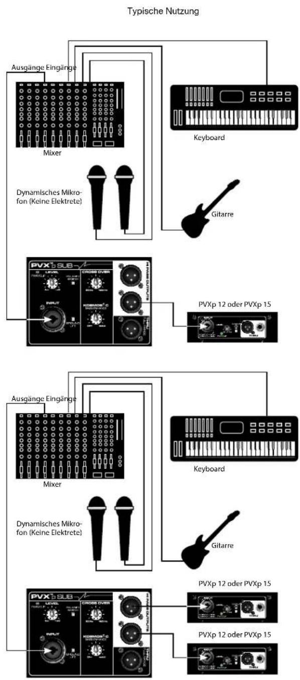
flowchart
graph TD
    A["Typische Nutzung"] --> B["Ausgänge Eingänge"]
    B --> C["Mixer"]
    C --> D["Dynamisches Mikrofon (Keine Elektrete)"]
    D --> E["Keyboard"]
    E --> F["Gitarre"]
    F --> G["PVXp 12 oder PVXp 15"]
    G --> H["Crossover"]
    H --> I["PVXp 12 oder PVXp 15"]
    I --> J["Mixer"]
    J --> K["Keycard"]
    K --> L["Keycard"]
    L --> M["Gitarre"]
    M --> N["PVXp 12 oder PVXp 15"]
    N --> O["PVXp 12 oder PVXp 15"]
    O --> P["Crossover"]
    P --> Q["Keycard"]
    Q --> R["Gitarre"]
    R --> S["PVXp 12 oder PVXp 15"]
    S --> T["PVXp 12 oder PVXp 15"]
In Transportposition:
27,06" × 16,75" × 24,25"
687 mm x 425 mm x 616 mm
Nettogewicht:
76.Lbs. (34.5 kg)
Montagevorrichtung:

INTERRUTTORE DIFFERENZIALE (1)
USCITE PASSO-ALTO (11 & 12)
USCITA THRU FULL RANGE (13)
DISCONNESSIONE DELL'UNITÀ PVX™P SUB DALLA RETE CA
![[613.96] 24.172 [601.50] 23.681 [425.41] 16.749](/content/2026/03/531500/images/8bd6a4bb2ecaa4683569f28bd3611f008f566b5aed988c05c2dc03813031ace4.jpg)
![[357.30] 14.067 [40.41] 1.591 [469.54] 18.486 [74.25] 2.923 [34.06] 1.341](/content/2026/03/531500/images/cbf258d0dfc8d17997780ec96b2bffae7772565e6c80e1c15d7daf85197a6881.jpg)
![[143.94] 5.667 [219.66] 8.648 [220.14] 8.667 [219.66] 8.648](/content/2026/03/531500/images/760c7c82e59e4f4507cc76b1e339b8dcd8b1f0963c0cff11502c53ad4c121914.jpg)

natural_image
Technical line drawing of a rectangular industrial enclosure with internal fan and mounting flanges (no text or symbols)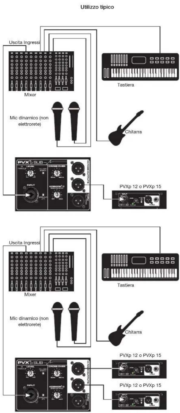
flowchart
graph TD
    A["Utilizzo tipico"] --> B["Mixer"]
    A --> C["Tastiera"]
    A --> D["Chitarra"]
    A --> E["PVXp 12 o PVXp 15"]
    A --> F["Uscita Ingressi"]
    A --> G["Mixer"]
    A --> H["PVXp 12 o PVXp 15"]
    A --> I["PVXp 12 o PVXp 15"]
    A --> J["Chitarra"]
    A --> K["MC dinamico (non elettrorete)"]
    A --> L["Mixer"]
    A --> M["PVXp 12 o PVXp 15"]
    A --> N["PVXp 12 o PVXp 15"]
Dimensioni (A x L x P)
In posizione d'uso:
24.25" x 16.75" x 23.00"
(ruote non incluse, prof. 4.06")
616 mm × 425 mm × 584 mm

AUTOMATSÄKRING (1)
IEC-NÄTSLADDSANSLUTNING (2)
PLACERA EN SATELLITHÖGTALARE UPPE PÅ PVX™P SUB
![[613.96] 24.172 [601.50] 23.681 [425.41] 16.749](/content/2026/03/531500/images/c191f1a6452f9ce7453f69decc99e3f174c37dd3ebe22967252c8d1cef68e4d4.jpg)
![[357.30] 14.067 [40.41] 1.591 [469.54] 18.486 [74.25] 2.923 [34.06] 1.341](/content/2026/03/531500/images/0cbe23224f0e0c655efc1e5841b750d8ac773b453a19204bfa19bd2f844f7c5c.jpg)
![[143.94] 5.667 [219.66] 8.648 [219.66] 8.648 [220.14] 8.667](/content/2026/03/531500/images/70072c32959ad2283ec72d7602f2c6e922d7b8518f53505660cc08c6ec0265c7.jpg)

natural_image
Technical line drawing of a rectangular industrial enclosure with internal fan and mounting flanges (no text or symbols)
flowchart
graph TD
    A["Typisk användning"] --> B["Mixer"]
    A --> C["Keyboard"]
    A --> D["Dynamisk Mic (Ingen elektret)"]
    A --> E["Gitarr"]
    A --> F["PVX 5 SUB"]
    A --> G["PVXp 12 eller PVXp 15"]
    A --> H["Mixer"]
    A --> I["Dynamisk Mic (Ingen elektret)"]
    A --> J["Gitarr"]
    A --> K["PVX 5 SUB"]
    A --> L["PVXp 12 eller PVXp 15"]
Frekvensområde (-10 dB, Half Space):
43 Hz - 180 Hz*
*Crossover Control helt medurs
Frekvenssvar, 1 Meter On-axis, Swept-sine In Anechoic Environment (-6 dB):
48 Hz - 138 Hz*
*Crossover Control helt medurs

KATKAISIJA (1)
![[613.96] [601.50] 24.172 23.681 [425.41] 16.749](/content/2026/03/531500/images/242961045fbfb8e875659797bffc00e4fd3cb794f17dcded2cd2ddc2f8c92744.jpg)
![[357.30] 14.067 [40, 1.5] [469.54] 18.486 [74, 2.9] [34.06] 1.341](/content/2026/03/531500/images/c27af71055f904c3a066413b6c161161909c59b55bbc17df99d3ad39278dcf96.jpg)
MITAT
![[143.94] 5.667 [219.66] 8.648 [220.14] 8.667 [219.66] 8.648](/content/2026/03/531500/images/4d27da73a3a739fe9482550ddbfa0ef1cafef23739f37af52a3b9b46a8177a35.jpg)
natural_image
Technical line drawing of a rectangular industrial enclosure with internal components and mounting flanges (no text or symbols)Tyypillinen käyttö

DISYUNTOR (1)
![[613.96] 24.172 [601.50] 23.681 [425.41] 16.749](/content/2026/03/531500/images/4b2c1ac5185c6a3c5983efc6ffe2223091251b94fa8b6b66f9f42680ce53f2bd.jpg)
![[357.30] 14.067 [40.41] 1.591 [469.54] 18.486 [74.25] 2.923 [34.06] 1.341](/content/2026/03/531500/images/2094169a1fb3ea92bfb9a148d1e146cb32985a968b33fd86667e8ef27ffa0a81.jpg)
![[143.94] 5.667 [219.66] 8.648 [220.14] 8.667 [219.66] 8.648](/content/2026/03/531500/images/fcf7c5d8672523e1ec6f20e5b77cbcb91fed6ff7ab48b03b80124dc5dc355411.jpg)

natural_image
Technical line drawing of a rectangular industrial enclosure with internal components and mounting holes (no text or symbols)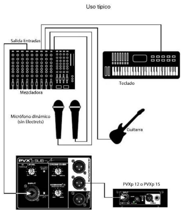

DISJUNTOR (1)
![[613.96] 24.172 [601.50] 23.681 [425.41] 16.749](/content/2026/03/531500/images/e97109dc56b32303b950b5eafa59785e559466e6e8b2b769ab27411fe7c6a054.jpg)
![[357.30] 14.067 [40.41] 1.591 [469.54] 18.486 [74.25] 2.923 [34.06] 1.341](/content/2026/03/531500/images/0828a9426e246aa4ed8a9458b46fb2402502f3f243a53aae524d8ac19bb0b594.jpg)
![[143.94] 5.667 [219.66] 8.648 [220.14] 8.667 [219.66] 8.648](/content/2026/03/531500/images/b89b379f45d181c71cc39256ac82f4f286cbf394d99990ee2145ef0dda15bf6c.jpg)

natural_image
Technical line drawing of a rectangular industrial enclosure with internal fan and mounting flanges (no text or symbols)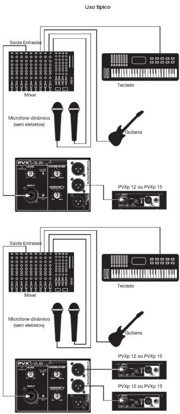
flowchart
graph TD
    A["Microfone dinâmico (sem eletretos)"] --> B["Mixer"]
    B --> C["Saida Entradas"]
    B --> D["Guitarra"]
    B --> E["Teclado"]
    B --> F["PVXp 12 ou PVXp 15"]
    B --> G["Saida Entradas"]
    G --> H["Mixer"]
    H --> I["Guitarra"]
    H --> J["PVXp 12 ou PVXp 15"]
    H --> K["PVXp 12 ou PVXp 15"]

회로 차단기 (1)
![[613.96] 24.172 [601.50] 23.681 [425.41] 16.749](/content/2026/03/531500/images/3ffe442883ecf489af1e89271dcad09099456974839fbbc7074c44de9639dd62.jpg)
![[357.30] 14.067 [40.41] 1.591 [469.54] 18.486 [74.25] 2.923 [34.06] 1.341](/content/2026/03/531500/images/30ec6153cba51dd45b23e84b37a0767a33987520e9560797e367700ccd8c4c1a.jpg)
치수
![[143.94] 5.667 [219.66] 8.648 [220.14] 8.667 [219.66] 8.648](/content/2026/03/531500/images/8c15d4026eeb6d1850afb0961ad54915a019cf054606c337f14b7d617121344f.jpg)

natural_image
Technical line drawing of a rectangular industrial enclosure with internal fan and mounting flanges (no text or symbols)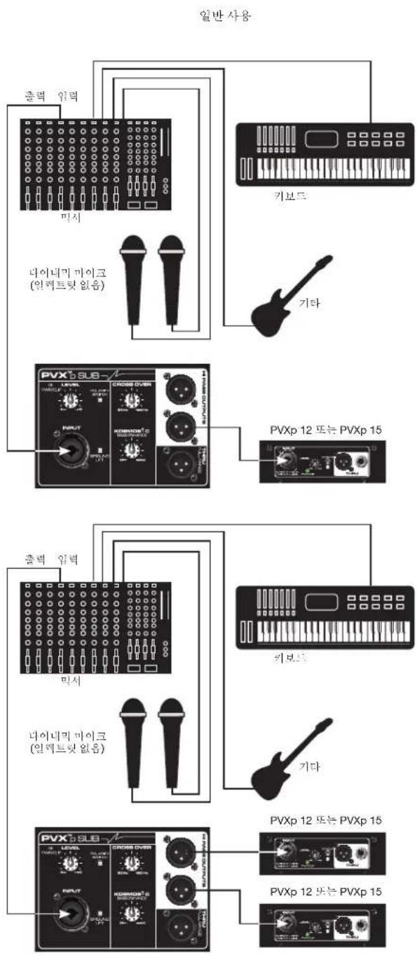
flowchart
graph TD
    A["미서"] --> B["PIER"]
    C["기타"] --> D["PVXp 12 또는 PVXp 15"]
    E["PIER"] --> F["PIER"]
    G["PIER"] --> H["PIER"]
    I["PIER"] --> J["PIER"]
    K["PIER"] --> L["PIER"]
    M["PIER"] --> N["PIER"]
    O["PIER"] --> P["PIER"]
    Q["PIER"] --> R["PIER"]
    S["PIER"] --> T["PIER"]
    U["PIER"] --> V["PIER"]
    W["PIER"] --> X["PIER"]
    Y["PIER"] --> Z["PIER"]
    AA["PIER"] --> AB["PIER"]
    AC["PIER"] --> AD["PIER"]
    AE["PIER"] --> AF["PIER"]
    AG["PIER"] --> AH["PIER"]
    AI["PIER"] --> AJ["PIER"]
    AK["PIER"] --> AL["PIER"]
    AM["PIER"] --> AN["PIER"]
    AO["PIER"] --> AP["PIER"]
    AQ["PIER"] --> AR["PIER"]
    AS["PIER"] --> AT["PIER"]
    AU["PIER"] --> AV["PIER"]
    AW["PIER"] --> AX["PIER"]
사양
Ground Lift Switch: 입력
전자적 크로스오버


电路断路器(1)
![[613.96] 24.172 [601.50] 23.681 [425.41] 16.749](/content/2026/03/531500/images/d7502608c51d65054a6b1aba441a6b6879a1c77af4a3d4722df66b90700e4510.jpg)
![[357.30] 14.067 [40.41] 1.591 [469.54] 18.486 [74.25] 2.923 [34.06] 1.341](/content/2026/03/531500/images/ead354cc836a4432befbf0f275d694ff1b8b048f8e6c2e8c5a6919084432e64f.jpg)
尺寸
![[143.94] 5.667 [219.66] 8.648 [220.14] 8.667 [219.66] 8.648](/content/2026/03/531500/images/d224658f6d4f0ad89ac67bf73a7d919803dc1837724e615d0d4b16e6b7c58117.jpg)

natural_image
Technical line drawing of a rectangular industrial enclosure with internal fan and mounting flanges (no text or symbols)典型用法
flowchart
graph TD
    A["混音器"] -->|输出 输入| B["电子琴"]
    A --> C["动态话筒 (无驻极体)"]
    C --> D["吉他"]
    C --> E["PVXp 12 或 PVXp 15"]

ブレーカー (1)
![[613.96] 24.172 [601.50] 23.681 [425.41] 16.749](/content/2026/03/531500/images/4506fd97b3508c15f5bd8c61fff396d6fbe2f467d6d6593390e9b92bed0ae531.jpg)
![[357.30] 14.067 [40.41] 1.591 [469.54] 18.486 [74.25] 2.923 [34.06] 1.341](/content/2026/03/531500/images/2cf8955db1c7dbb9e93b170afc63fa2070cc461016d5105cce54fbe9332d9fe2.jpg)
寸法
![[143.94] 5.667 [219.66] 8.648 [220.14] 8.667 [219.66] 8.648](/content/2026/03/531500/images/10443276691ad59b58c53997c2bc44d4d7c177d9a8138289dd83cc583b71f71e.jpg)

natural_image
Technical line drawing of a rectangular industrial enclosure with internal components and mounting holes (no text or symbols)使用例

Effective Date: 09/15/2010
What This Warranty Covers
Your Peavey Warranty covers defects in material and workmanship in Peavey products purchased and serviced in the U.S.A. and Canada.
What This Warranty Does Not Cover
The Warranty does not cover: (1) damage caused by accident, misuse, abuse, improper installation or operation, rental, product modification or neglect; (2) damage occurring during shipment; (3) damage caused by repair or service performed by persons not authorized by Peavey; (4) products on which the serial number has been altered, defaced or removed; (5) products not purchased from an Authorized Peavey Dealer.
Who This Warranty Protects
This Warranty protects only the original purchaser of the product.
How Long This Warranty Lasts
The Warranty begins on the date of purchase by the original retail purchaser. The duration of the Warranty is as follows:
| Product Category Duration | |
| Guitars/Basses, Amplifiers, Preamplifiers, Mixers, Electronic Crossovers and Equalizers 2 years *(+ 3 years) | |
| Drums 2 years *(+ 1 year) | |
| Enclosures 3 years *(+ 2 years) | |
| Digital Effect Devices and Keyboards and MIDI Controllers 1 years *(+ 1 year) | |
| Microphones 2 years | |
| Speaker Components(incl. Speakers, Baskets, Drivers, Diaphragm Replacement Kits and Passive Crossovers) | 1 year |
| Tubes and Meters | 90 Days |
| Cables Limited Lifetime | |
| AmpKit Link, Xport, Rockmaster Series, Strum'n Fun, RetroFire, GT & BT Series Amps | 1 year |
[* Denotes additional Warranty period applicable if optional Warranty Registration Card is completed and returned to Peavey by original retail purchaser within 90 days of purchase.]
What Peavey Will Do
We will repair or replace (at Peavey's discretion) products covered by Warranty at no charge for labor or materials. If the product or component must be shipped to Peavey for Warranty service, the consumer must pay initial shipping charges. If the repairs are covered by Warranty, Peavey will pay the return shipping charges.
How To Get Warranty Service
(1) Take the defective item and your sales receipt or other proof of date of purchase to your Authorized Peavey Dealer or Authorized Peavey Service Center. OR
(2) Ship the defective item, prepaid, to Peavey Electronics Corporation, International Service Center, 412 Highway 11 & 80 East, Meridian, MS 39301. Include a detailed description of the problem, together with a copy of your sales receipt or other proof of date of purchase as evidence of Warranty coverage. Also provide a complete return address.
Limitation of Implied Warranties
ANY IMPLIED WARRANTIES, INCLUDING WARRANTIES OF MERCHANTABILITY AND FITNESS FOR A PARTICULAR PURPOSE, ARE LIMITED IN DURATION TO THE LENGTH OF THIS WARRANTY.
Some states do not allow limitations on how long an implied Warranty lasts, so the above limitation may not apply to you.
Exclusions of Damages
PEAVEY'S LIABILITY FOR ANY DEFECTIVE PRODUCT IS LIMITED TO THE REPAIR OR REPLACEMENT OF THE PRODUCT, AT PEAVEY'S OPTION. IF WE ELECT TO REPLACE THE PRODUCT, THE REPLACEMENT MAY BE A RECONDITIONED UNIT. PEAVEY SHALL NOT BE LIABLE FOR DAMAGES BASED ON INCONVENIENCE, LOSS OF USE, LOST PROFITS, LOST SAVINGS, DAMAGE TO ANY OTHER EQUIPMENT OR OTHER ITEMS AT THE SITE OF USE, OR ANY OTHER DAMAGES WHETHER INCIDENTAL, CONSEQUENTIAL OR OTHERWISE, EVEN IF PEAVEY HAS BEEN ADVISED OF THE POSSIBILITY OF SUCH DAMAGES.
Some states do not allow the exclusion or limitation of incidental or consequential damages, so the above limitation may not apply to you.
This Warranty gives you specific legal rights, and you may also have other rights which vary from state to state.
If you have any questions about this Warranty or services received or if you need assistance in locating an Authorized Service Center, please contact the Peavey International Service Center at (601) 483-5365.
Features and specifications are subject to change without notice.
Optional Product Extended Warranty Registration
Give us some information and put your extended warranty into effect!
Please take a few minutes to fill out this information/survey sheet to help us get to know and serve you better.
To save time, submit your warranty registration online at www.peavey.com/support/warrantyregistration
1.
First Name
Initial Last Name
Street Address
City
State/Province
Postal Code
( )
Telephone Number
E-mail Address
( )
.
Fax Number
Date of Birth
Gender
□M
□F
2.

Model
8-Digit Serial Number
Date of Purchase
Price Paid
3.
Name of store where purchased
City
State
- Top two (2) reasons why you purchased from this store/dealer:
□ Availability of product
□ Past favorable experience
□ Friend/Relative's recommendation
□ Best price
□ Store credit card
□ Advertised special
□ Knowledgeable staff
□ Convenient location
□ Availability of lessons
□ Received as a gift
□ Technical instruction
□ Other
- Where do you most often shop for music and sound products?
□ Independent retailer
□ Newspaper ads
□ Mass market retailer
□ Internet/Web sites
□ Mail order magazines
□ Other
- What two (2) factors most influenced your purchase of this product?
□ Peavey brand name
□ Product appearance
Craftsmanship
□ Durability
□ Features for price
□ Prior experience with Peavey
□ Bundled accessories
Packaging
□ Sound quality
□ Other
- How did you learn about this Peavey product? (select best answer)
□ Magazine review
□ Teacher's recommendation
□ Newspaper review
□ Catalog or flyer
□ Radio advertisement
□ Saw in store
□ Advertised special
□ Use by professional
□ Friend/Relative's recommendation
□ Other
□ Salesperson's recommendation
-
Which other brands/models did you consider?
-
How would you describe your level of musicianship/technical expertise?
☐ Beginner - Never played or taken less than one (1) year of lessons
□ Intermediate - One (1) to five (5) years of lessons or playing
□ Advanced - More than five (5) years of lessons or playing; play professionally
- Education: (select best answer)
□ High school
□ Some college
□ Completed college
□ Graduate school
- Which best describe your family income? (select best answer)
□ Under \$15,000
□ \75,000 - \99,999
□ \15,000 - \24,999
□ \100,000 - \149,999
□ \25,000 - \34,999
Over - \$150,000
□ \35,000 - \49,999
□ \50,000 - \74,999
- Which of the following is your primary source of information on musical products: (select best answer)
□ Television
□ Mail order catalogs
□ Radio
□ Direct mail
□ Internet
□ Literature from manufacturer
□ Newspaper
□ Other
□ Magazines
- What is your main motivation for buying new equipment?
□ Replacing old product
Impulse
□ Want new and leading edge
□ Need for improved performance
equipment
□ New technology
□ Fullfill a specific need
□ Availability of product
□ Supplement existing products
□ Other
□ Value
-
Please list your three most frequently visited Web sites.
-
http://
-
http://
-
http://
-
In your opinion, what could Peavey do to improve its products and/or service? Please use the space below to tell us your answer.
Meridian, Ms 39302-5108
P.O. Box 5108
Attn: Warranty Department
Peaey Electronics Corporation

Here
Postage
Place