FWDS42E1 - Monitor SONY - Free user manual and instructions
Find the device manual for free FWDS42E1 SONY in PDF.
User questions about FWDS42E1 SONY
0 question about this device. Answer the ones you know or ask your own.
Ask a new question about this device
Download the instructions for your Monitor in PDF format for free! Find your manual FWDS42E1 - SONY and take your electronic device back in hand. On this page are published all the documents necessary for the use of your device. FWDS42E1 by SONY.
USER MANUAL FWDS42E1 SONY
Flat Wide Display Monitor
| 取吸説明書 | JP |
| Operating Instructions | GB |
| Mode d'emploi | FR |
| Bedienungsanleitung | DE |
| Manual de instrucciones | ES |
| Istruzione per l'uso | IT |
| 使用说明书 | CS |
附上上的本题的习题和习题答案。
© 2009 Sony Corporation
()
Sony Corporation Printed in Korea
安全のたに
ID MODE (ON/O-9/SET/C/OFF) モタ
The model and serial numbers are located on the rear. Record the model and serial numbers in the spaces provided below. Refer to these numbers whenever you call upon your Sony dealer regarding this product.
Model No. __ Serial No. ____
To reduce the risk of fire or electric shock, do not expose this apparatus to rain or moisture.
To avoid electrical shock, do not open the cabinet. Refer servicing to qualified personnel only.
THIS APPARATUS MUST BE EARTHED.
On transportation
When you carry the display unit, hold the unit itself, not the speakers. If you fail to do so, the speakers may come out of the unit and the unit may fall. This can cause injury.
WARNING
When installing the unit, incorporate a readily accessible disconnect device in the fixed wiring, or connect the power plug to an easily accessible socket-outlet near the unit.
If a fault should occur during operation of the unit, operate the disconnect device to switch the power supply off, or disconnect the power plug.
For the customers in the U.S.A.
If you have any questions about this product, you may call; Sony Customer Information Services Center 1-800-222-7669 or http://www.sony.com/
Declaration of Conformity
Trade Name: SONY
Model: FWD-S42E1
Responsible Party: Sony Electronics Inc.
Address: 16530 Via Esprillo, San
Diego, CA 92127 U.S.A.
Telephone Number: 858-942-2230
This device complies with Part 15 of the FCC Rules. Operation is subject to the following two conditions: (1) This device may not cause harmful interference, and (2) this device must accept any interference received, including interference that may cause undesired operation.
This equipment has been tested and found to comply with the limits for a Class B digital device, pursuant to Part 15 of the FCC Rules. These limits are designed to provide reasonable protection against harmful interference in a residential installation. This equipment generates, uses, and can radiate radio frequency energy and, if not installed and used in accordance with the instructions, may cause harmful interference to radio communications. However, there is no guarantee that interference will not occur in a particular installation. If this equipment does cause harmful interference to radio or television reception, which can be determined by turning the equipment off and on, the user is encouraged to try to correct the interference by one or more of the following measures:
- Reorient or relocate the receiving antenna.
- Increase the separation between the equipment and receiver.
- Connect the equipment into an outlet on a circuit different from that to which the receiver is connected.
- Consult the dealer or an experienced radio/TV technician for help.
You are cautioned that any changes or modifications not expressly approved in this manual could void your authority to operate this equipment.
All interface cables used to connect peripherals must be shielded in order to comply with the limits for a digital device pursuant to Subpart B of Part 15 of FCC Rules.
WARNING: THIS WARNING IS APPLICABLE FOR USA ONLY.
If used in USA, use the UL LISTED power cord specified below.
DO NOT USE ANY OTHER POWER CORD.
Plug Cap Parallel blade with ground pin (NEMA 5-15P Configuration)
Cord Type SJT or SVT, three 16 or 18 AWG wires
Length Minimum 1.5m (4 ft .11 in.), Less than 2.5 m (8 ft. 3 in.)
Rating Minimum 6A, 125V
Using this unit at a voltage other than 120V may require the use of a different line cord or attachment plug, or both.
To reduce the risk of fire or electric shock, refer servicing to qualified service personnel.
For the customers in Canada
This Class B digital apparatus complies with Canadian ICES-003.
The socket-outlet should be installed near the equipment and be easily accessible.
For the customers in Europe
The manufacturer of this product is Sony Corporation, 1-7-1 Konan, Minato-ku, Tokyo, Japan.
The Authorized Representative for EMC and product safety is Sony Deutschland GmbH, Hedelfinger
Strasse 61, 70327 Stuttgart, Germany. For any service or guarantee matters please refer to the addresses
given in separate service or guarantee documents.
WARNING: THIS WARNING IS APPLICABLE FOR OTHER COUNTRIES.
- Use the approved Power Cord (3-core mains lead) / Appliance Connector / Plug with earthing-contacts that conforms to the safety regulations of each country if applicable.
- Use the Power Cord (3-core mains lead)/Appliance Connector/Plug conforming to the proper ratings (Voltage, Ampere).
If you have questions on the use of the above Power Cord / Appliance Connector / Plug, please consult a qualified service personnel.
IMPORTANT INFORMATION
If a television is not positioned in a sufficiently stable location, it can be potentially hazardous due to falling. Many injuries, particularly to children, can be avoided by taking simple precautions such as:
- Using cabinets or stands recommended by the manufacturer of the television.
- Only using furniture that can safely support the television.
- Ensuring the television is not overhanging the edge of the supporting furniture.
- Not placing the television on tall furniture (for example, cupboards or bookcases) without anchoring both the furniture and the television to a suitable support.
- Not standing the televisions on cloth or other materials placed between the television and supporting furniture.
- Educating children about the dangers of climbing on furniture to reach the television or its controls.
For kundene i Norge
Dette utstyret kan kobles til et IT-stromforderdingssystem.
Table of Contents
Introduction
Precautions 6
Recommendations on Installation 8
Location and Function of Parts and Controls
Front. 9
Rear 10
Remote Control 13
Button Description 13
Special Buttons on the Remote Control 15
Using the Wide Mode 15
Using the ID MODE button 16
Optional Adaptors 17
Connections
Connecting the Speakers. 19
Connecting the AC Power Cord 19
Cable Management 20
Using the Settings
Overview of the Menus 21
Picture/Sound Settings 22
Screen Settings 24
Setup Settings 26
Network Functions
Preparations for Using the Network Functions 30
Other Information
Troubleshooting 32
Input Signal Reference Chart 34
Specifications 36
Index 38
Introduction
Precautions
On safety
- A nameplate indicating operating voltage, power consumption, etc. is located on the rear of the unit.
- Should any solid object or liquid fall into the cabinet, unplug the unit and have it checked by qualified personnel before operating it any further.
- Unplug the unit from the wall outlet if it is not to be used for several days or more.
- To disconnect the AC power cord, pull it out by grasping the plug. Never pull the cord itself.
Cleaning
Be sure to unplug the power cord before cleaning the display.
On cleaning the display
Do not allow hard objects to scrape, or pound the display screen surface, or allow objects to hit the screen surface because that can damage the screen surface. The display screen has a special surface treatment. Follow the instructions below to prevent impair performance because of improper handling when cleaning.
- Gently remove any dust from the screen surface with a soft cloth. A cleaning cloth or cloth for wiping glasses is preferred.
- If it is excessively dirty, clean the screen surface with a soft cleaning cloth slightly dampened with water.
- Never use alcohol, benzine, thinner, acid or alkaline cleaning solvent, abrasive cleaners, or chemically-treated cloths because they will damage the screen surface.
Cleaning the cabinet
- Gently wipe off stains using a dry, soft cloth. Wipe off grimy stains using a cloth slightly moistened with a mild detergent, then wipe the area again using a dry, soft cloth.
- Do not use alcohol, benzine, thinner or insecticide. Doing so may damage the finish of the surface or remove the markings on the unit.
- There is a danger that the screen will be damaged if wiped with a cloth that is dirty.
- Allowing the unit to come into prolonged contact with rubber or plastic products may alter the unit or cause the protective coating to come off.
On the LCD panel
- Keeping the LCD panel facing toward the sun for a long time will damage the panel. Take this into account when you install the unit outdoor or by a window.
- Do not forcefully press or scratch the LCD screen. Do not place objects on the screen. Doing so may disrupt the display or damage the LCD screen.
- You may find that the screen is showing horizontal stripes or that it has afterimage. The screen may also look darker when using the unit in a cool environment. These do not indicate a screen malfunction. The screen will return to normal when the ambient temperature is higher.
- If a static image is displayed for a long time, screen burn or a residual image may occur. A residual image will disappear over time. If ghosting occurs, use the
screensaver function, or use some kind of video or imaging software to provide constant movement on the screen. If light ghosting (image burn-in) occurs, it may become less conspicuous, but once burn-in occurs, it will never completely disappear.
- The panel surface, cabinet or frame may warm up during use. This does not a problem.
Bright spots and dark spots on the LCD screen
Although the LCD screen is manufactured by high technology with an effective resolution of at least 99.99% , it may show dark spots (pixel defects) or bright spots (red, blue, green, etc.) that are continuously lit or flashing. These are phenomenon of LCD screens that generated sometimes by pixel defects. These may occur after the device has been used for an extended period of time.
These are not screen malfunctions.
On installation
- Always verify that the unit is operating properly before use. SONY WILL NOT BE LIABLE FOR DAMAGES OF ANY KIND INCLUDING, BUT NOT LIMITED TO, COMPENSATION OR REIMBURSEMENT ON ACCOUNT OF THE LOSS OF PRESENT OR PROSPECTIVE PROFITS DUE TO FAILURE OF THIS UNIT, Either DURING THE WARRANTY PERIOD OR AFTER EXPIRATION OF THE WARRANTY, OR FOR ANY OTHER REASON WHATSOEVER.
- Allow adequate air circulation to prevent internal heat build-up. Do not place the unit on surfaces (rugs, blankets, etc.) or near materials (curtains, draperies) that may block the ventilation holes.
- Do not install the unit in a location near heat sources such as radiators or air ducts, or in a place subject to direct sunlight, excessive dust, mechanical vibration or shock.
- When you install multiple equipment with the unit, the following problems, such as malfunction of the remote control, noisy picture, noisy sound, may occur depending on the position of the unit and other equipment.
On repacking
Do not throw away the carton and packing materials. They make an ideal container in which to transport the unit. When shipping the unit, repack it as illustrated on the carton.
If you have any questions on this unit, contact your authorized Sony dealers.
For the State of California, USA only
Perchlorate Material - special handling may apply, See www.dtsc.ca.gov/hazardouswaste/perchlorate Perchlorate Material : Lithium battery contains perchlorate.
For the customers in the USA
Lamp in this product contains mercury. Disposal of these materials may be regulated due to environmental considerations. For disposal or recycling information, please contact your local authorities or the Electronic Industries Alliance (www.eiae.org).
For the customers in Taiwan only
廢電池請回收

Recommendations on Installation
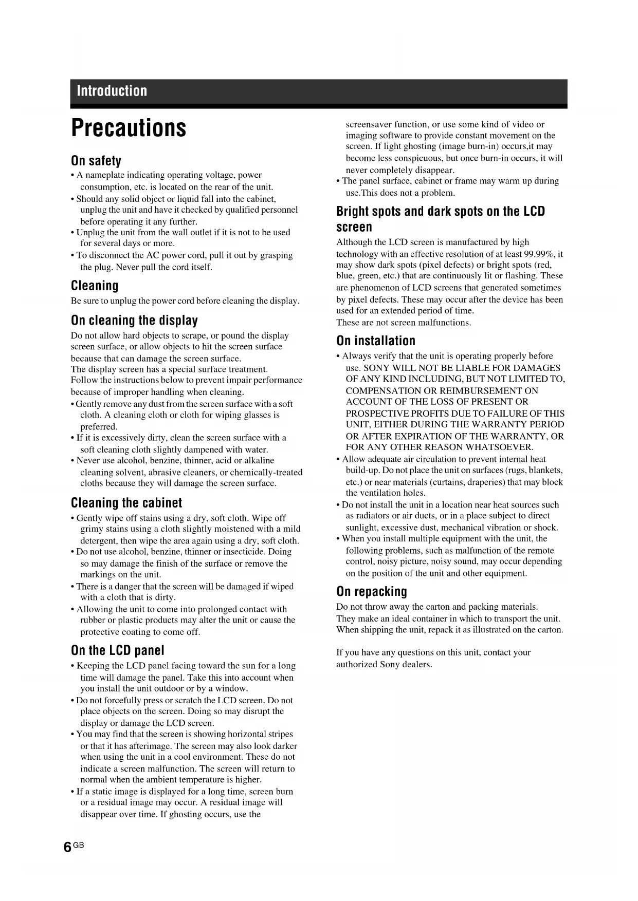
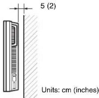
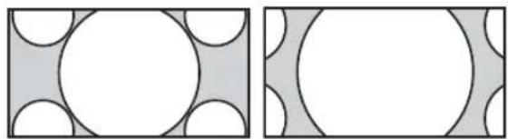
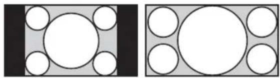
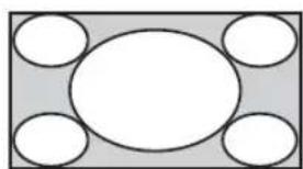
Provide an ample amount of space around the display
- To prevent internal heat buildup from sealing off the display, make sure to ensure proper ventilation by leaving open the minimum amount of space around the display, as illustrated below.
- The ambient temperature must be 0^ to 40^ (32°F to 104°F). Be careful when installing the display near a ceiling. The temperature there can become much higher than the normal, lower-level room temperature.
- When using the stand, you use the applicable Tabletop Stand SU-S01 (not supplied). For the fitting method, see the instruction manual of the Tabletop Stand.
- Regarding the installation of hardware such as brackets, screws, or bolts, we cannot specify the products. Actual installation is up to the authorized local dealers. Consult with qualified Sony personnel for installation.
- While the display is on, a certain amount of heat builds up inside. This can cause burns. Avoid touching the top or rear of the display when it is powered on or just after it has entered standby mode.
When using the Tabletop Stand Front
Side
10 (4)
Notes
- When moving or installing the display when it is attached to the stand (not supplied), do so with at least 2 people.
- When a VESA mount compatible stand or the like is installed, the recommended value for the screw tightening torque is 2N· m (20kgf·cm).
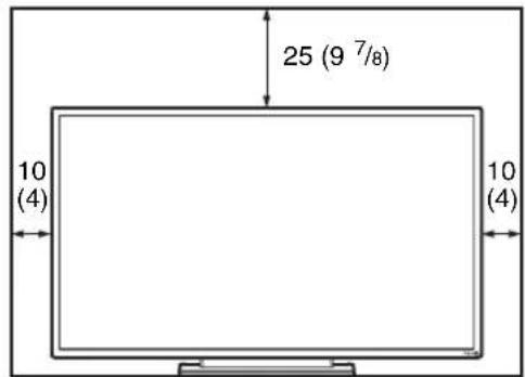
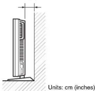
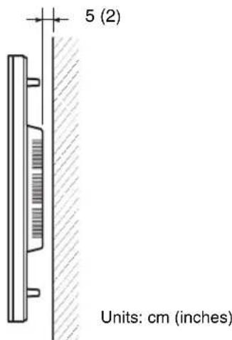
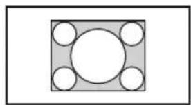
When mounting the display horizontally
Front
Side
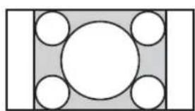
When mounting the display vertically
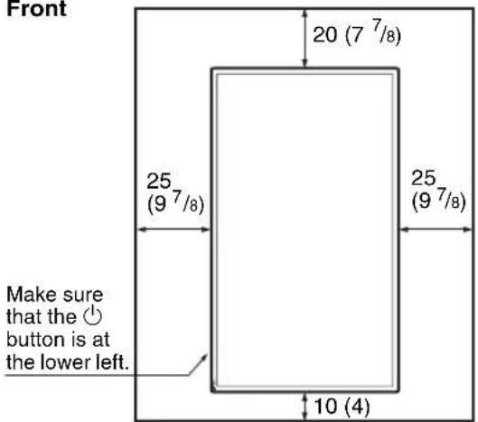
Front
Side
Location and Function of Parts and Controls
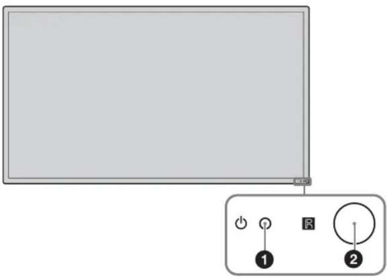
Front
Parts Description
(power/stand by) indicator
- Lights up in green when the display is switched on.
- Lights up in red when the display is in standby mode. Lights up in orange when the display enters the power saving mode while a signal is input from a PC. When the indicator blinks in red, see page 32.
Note
When the "LED" option in the "Multi Display" settings is set to "Off" and the "Position" option is not set to the right-bottom, the indicator does not light up in green even when the display is turned on, except for the case of no signal or an unsupported signal.
Remote control sensor Remote control light receptor.

Rear
| Parts Description | |
| 1 Main power switch | Turn the main power switch to “ON”(press the | side) when setting up the device. When the main power switch is turned “OFF” (press the ①le), the power consumption is 0W. |
| 2 AC IN socket | Connect the supplied AC power cord to this socket and to a wall outlet. See page 19. Once you connect the AC power cord and turn on main power switch, the ① indicator lights up in red and the display goes into the standby mode. |
| 3 SPEAKER socket | Connect the speakers SS-SPG02 (not supplied) to this socket. For more details on connecting the speakers, see the operating manual that came with the speakers. For details on how to route the speaker cords, see page 20. |
| 4 Speaker installation positions | Attach the dedicated speakers SS-SPG02. |
| 5 Stand installation holes | Screw holes conforming to VESA standard. (Pitch: 400mm × 400mm, Screw: M6) Note When a VESA mount compatible stand or the like is installed, the recommended value for the screw tightening torque is 2N·m (20kgf·cm). |
| 6 Applicable Tabletop Stand installation holes | Use these hooks to install the Tabletop Stand SU-S01 (not supplied). |
| 7 Dedicated Tabletop Stand installation hole cover | Remove when mounting the Tabletop Stand SU-S01 (not supplied). |
| 8 (power) | Switches the display on or off (standby). Operate when the main power switch is “ON” ( $ide). |
| 9 INPUT/ + (enter) | Press to select a signal to be input from the HD15 (RGB/COMPONENT) IN connector, DVI IN connector or OPTION slot. The signal to be input switches as follows each time you press the INPUT button. → HD15→DVI→OPTION→ When an optional adaptor supporting the video signal is not installed in the OPTION slot, OPTION will be skipped. Press to set your choice. |
| 10 (volume/cursor) +/-/0/0 | Press to control speaker volume. When the menu is displayed, press to move the cursor or set a value. Press to set your choice. |
| 11 MENU/ (return) | Press to show menus. This returns to the preceding menu screen. |
| 12 CONTROL S OUT (Mini jack) | You can control pieces of multiple equipment with a single remote control when the display is connected to the CONTROL S IN jack of the video equipment or another display. |
| 13 REMOTE (D-sub 9-pin) | This connector allows remote control of the display using the RS-232C protocol. For details, contact your authorized Sony dealers. |
| 14 HD15 (RGB/COMPONENT) (D-sub 15-pin) | HD15 (RGB/COMPONENT) IN: Connects to the analog RGB signal or component signal output of a piece of video equipment or PC. See page 37. AUDIO IN: Inputs an audio signal. Connects to the audio signal output of a piece of video equipment or PC. |
| 15 AUDIO (Stereo mini jack) | Note When inputting a component signal, be sure not to input sync signals to pins 13 and 14. If you do so, the picture may not be displayed properly. |
| 16 DVI (DVI-D 24-pin) | DVI IN: Connects to the digital signal output terminal of the video equipment or PC. Supports HDCP copy protection. |
| 17 AUDIO (Stereo mini jack) | AUDIO IN: Inputs an audio signal. Connects to the audio signal output of a piece of video equipment, etc. |
Parts Description
16 OPTION slot (VIDEO/COM port)
This slot supports video signals and communication functions. Attach an optional adaptor (the BKM-FW series) in this slot to extend monitor functions. See page 17.
Remote Control
Button Description
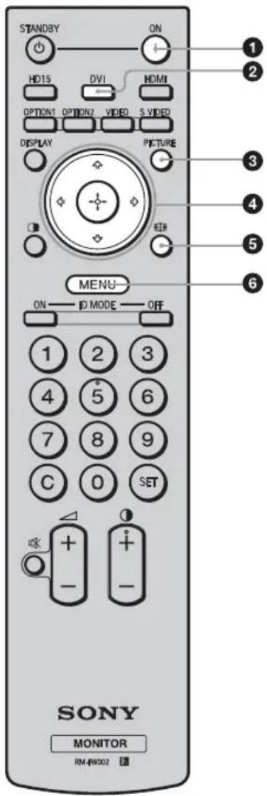
ON (power on) button
Press to turn the display on.
Operate when the main power switch on the backside of the display is "ON."
DVI button
Press to select the signal input to the DVI connector.
③PICTURE button
Selects "Picture Mode". Each press toggles between "Vivid", "Standard", "Custom", and "Conference".
4 12 = 12 +12 = 12 (arrow/enter) buttons
The 口 /口 /口 buttons move the menu cursor and set values, etc.
Pressing button sets the selected menu or setting items.
(whole mode) button
Press to change the aspect ratio. See page 15.
6 MENU button
Press to show menus. Press again to hide them. See page 21.
Notes
- The 5 button and button have a tactile dot. Use the tactile dot as a reference when operating the display.
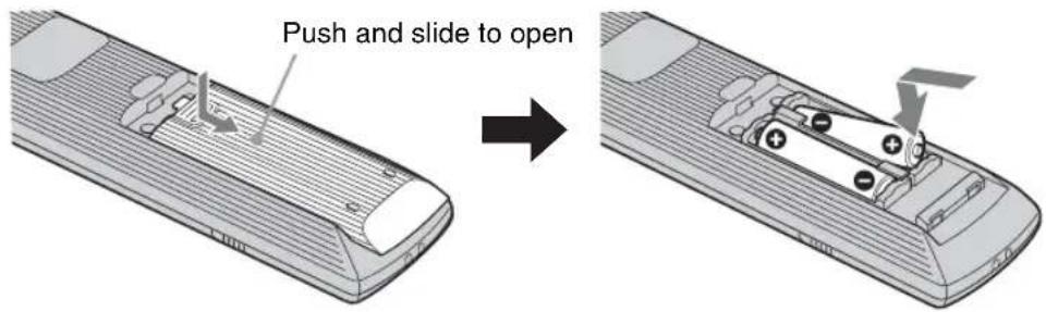
- Insert two size AA (R6) manganese batteries (supplied) by matching the and on the batteries to the diagram inside the remote control's battery compartment.
Caution
Danger of explosion if battery is incorrectly replaced. Replace only with the same or equivalent type recommended by the manufacturer. When you dispose of the battery, you must obey the law in the relative area or country.
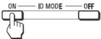
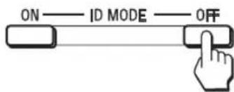
7ID MODE (ON/0-9/SET/C/OFF) buttons
You can operate a specific display without affecting other displays installed at the same time.
- ON button: Press to show the "Index Number" on the screen.
- 0-9 button: Press to enter the "Index Number" of the display you want to operate.
- SET button: Press to set the input "Index Number".
- C button: Press to clear the input "Index Number".
- OFF button: Press to return to the normal mode. See page 16.
8 (contrast) +/- button
Adjusts the picture (contrast) level.
( volume) +/- button
Press to adjust the volume.
( mating) button
Press to mute the sound. Press again to restore sound.
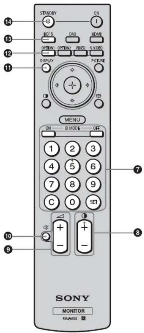
DISPLAY button
Press to display the currently selected input, the type of the input signal and the "Aspect" setting on the screen. Press again to hide them. If this displayed information is left undisturbed for a short time, it will disappear automatically.
OPTION 1 button
When an optional adaptor is installed, selects an input signal from the equipment connected to the optional adaptor.
If the installed optional adaptor has multiple input connectors, each press of the button toggles between the input signals.
HD15 button
Press to select the input signal of the HD15 (RGB/COMPONENT) connector. The RGB signal or component signal is selected automatically or manually in accordance with the menu settings.
14 STANDBY button
Press to change the display to the standby mode.
Note
You cannot use the HDMI button, the OPTION 2 button, the VIDEO button, the SVIDEO button and the button on this display.
Special Buttons on the Remote Control
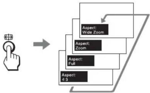
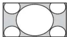
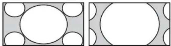
Using the Wide Mode
You can change the aspect ratio of the screen.
Tip
You can also access the "Aspect" settings in the "Screen" settings. See page 25.
For input from video equipment such as Video, DVD, etc. (other than PC input)
4:3 Original Source


Wide
Zoom
Zoom

Full
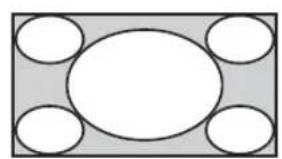
4:3

16:9 Original source
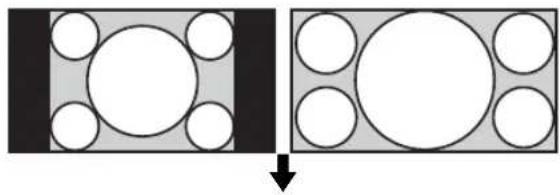
Wide Zoom
Zoom
Full
4:3

For PC Input
Illustrations below indicate the input resolution of 1,024 × 768
Real
Full 1
Full 2
Note
If the input resolution is higher than the panel resolution (1,920× 1,080) , the display of Real is the same as Full 1.
Using the ID MODE button
You can operate a specific display without affecting other displays installed at the same time.
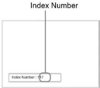
1 Press ON button.
Display's "Index Number" appears in black characters on the lower left menu on the screen. (Every display is allocated an individual preset "Index Number" from 1 to 255.)
2 Input the "Index Number" of the display you want to operate using the 0 - 9 buttons on the remote control.
The input number appears right next to the "Index Number" of each display.
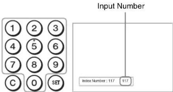
3 Press SET button.
The characters on the selected display change to green while the others change to red.

You can operate the specified display indicated with green characters only. Only the operation of ON button and STANDBY/ID MODE-OFF button is effective t other displays, as well.
4 When all of the setting changes have been completed, press OFF button.
The display returns to the normal screen.
To correct the Index Number
Press the C button to clear the current input "Index Number". Return to Step 2, and input a new "Index Number".

Tip
To change the "Index Number" of the display, see "Index Number" in "Control Setting" on page 26.
Optional Adaptors
The terminal of the OPTION slot (page 12) on the side of the equipment is a slot-in type. It can be switched to the following optional adaptors (not supplied).
For details on installation, consult your Sony dealers. For details on the optional adaptors for system expansion, see each instruction manual with this manual.
COMPONENT/RGB INPUT Adaptor BKMFW11
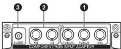
Y / G,PB / CB / B,PR / CR / R IN connector (BNC): Connects to the analog RGB signal or component signal output of a piece of video equipment or PC.
HD, VD IN connector (BNC): Connects to the synchronization signal output of a PC.
Note
When inputting a component signal, be sure not to input sync signals to the HD and VD connectors. If you do so, the picture may not be displayed properly.
3 AUDIO jack (Stereo mini jack): Connects to the audio output of a piece of video equipment or PC.
HDMI INPUT Adaptor BKM-FW15
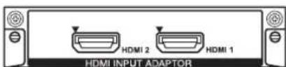
Connects to the HDMI signal output of a piece of video equipment or PC. You can enjoy enhanced or high-definition video, and two-channel digital audio.
Notes
- Be sure to use only an HDMI cable (not supplied) that bears the HDMI logo. We recommend that you use a Sony HDMI cable (high speed type).
HDMI control is supported by serial numbers 7000001 onwards.
HD-SDI/SDI INPUT Adaptor BKM-FW16
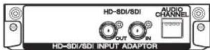
Connects to the HD-SDI signal output of a piece of video equipment.
MONITOR CONTROL Adaptor BKM-FW21
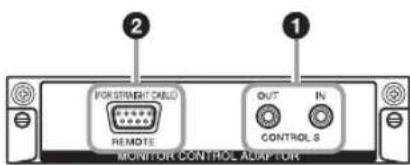
1CONTROL S IN/OUT jack (Mini jack): You can control pieces of multiple equipment with a single remote control when the display is connected to the CONTROL S jack of the video equipment or another display.
2REMOTE connector (D-sub 9-pin): You can remote control of the display using the RS-232C protocol. For details, contact your authorized Sony dealers.
Note
You cannot use the REMOTE connector of this display if the adaptor is connected to this display. Use the REMOTE connector of this adaptor.
NETWORK MANAGEMENT Adaptor BKMFW32
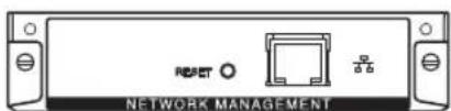
You can connect this device to the network with a LAN cable (10BASE-T/100BASE-TX). You can assign various settings and control the display via the network from a PC.
Caution
For safety, do not connect the connector for peripheral device wiring that might have excessive voltage to this port. For this port, follow the instruction manual of the optional adaptor.
Note
You cannot use the REMOTE connector of this display if the adaptor is connected to this display.
STREAMING RECEIVER Adaptor BKM-FW50
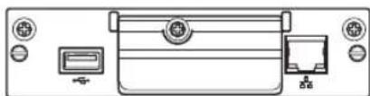
You can use this display for digital signage.
You can easily play back movies, still images or background music in designated data formats by just inserting a recording media. You can also use a network to view images from a remote computer on the display.
Caution
- For safety, do not connect the connector for peripheral device wiring that might have excessive voltage to this port. For this port, follow the instruction manual of the optional adaptor.
- Some functions are limited with BKM-FW50 Web control.
Note
You cannot use the REMOTE connector of this display if the adaptor is connected to this display.
Connections
Before you start
- First make sure that the power of each piece of equipment is turned off.
- Use cables suitable for the equipment to be connected.
- Connect the cables, fully inserting them into the connectors or jacks. A loose connection may cause hum and other noise.
- To disconnect the cable, pull it out by grasping the plug. Never pull the cable itself.
See the instruction manual of the equipment to be connected, too. - Insert the plug securely into the AC IN socket.
- Use one of the two AC plug holders (supplied) to securely hold the AC plug.
Connecting the Speakers
Connect the speakers SS-SPG02 (not supplied). To connect, use the following speaker cords included with the speakers.
Speaker cord (without terminal cover)
Please be sure to connect the speakers correctly. For more details on connecting the speakers, see the operating manual of the speakers. For details on how to route the speaker cords, see page 20.
Connecting the AC Power Cord
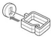
1 Plug the AC power cord into the AC IN socket. Then, attach the AC plug holder (supplied) to the AC power cord.

2 Slide the AC plug holder over the cord until it connects to the AC IN socket cover.
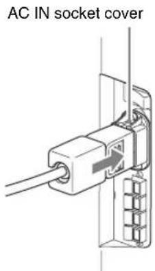
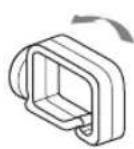
To remove the AC power cord
After squeezing the AC plug holder and freeing it, grasp the plug and pull out the AC power cord.
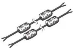
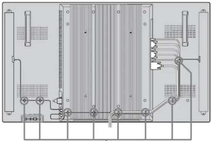
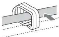
Cable Management
Using the cable holders
You can neatly bundle the cables with the cable holders provided. Attach the cable holders as shown in the illustrations below.
Rear
①

②

(3)
Using the Settings
Overview of the Menus
The settings provide you access to the following features:
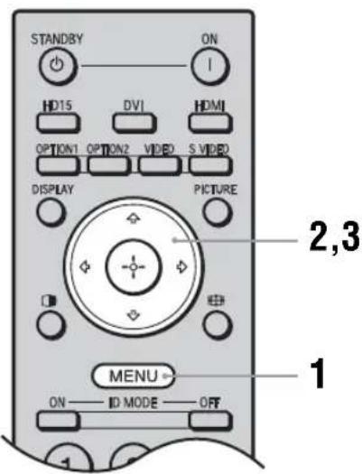
1 Press MENU button.
2 Press 四 /四 buttons to highlight the desired menu icon.
3 Press button or button.
To highlight an option and to change settings in each menu screen, press 12 / 12 / 12 buttons. Press button to confirm the selection. To exit the menu, press MENU button.
To change the on-screen language
Select the desired language for on-screen settings and messages from "English", "François", "Deutsch", "Espanol", "Italiano" or "日本語" "English" (English) is set for the default setting. See page 26.
Settings Allows you to set/change
Picture/Sound
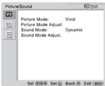
Picture Mode: (page 22)
Picture Mode Adjust. (page 22)
Sound Mode: (page 23)
Sound Mode Adjust. (page 23)
Note
You cannot set or change "Picture Mode" or "Picture Mode Adjust." when there is no signal input.
Screen
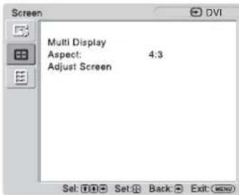
Multi Display (page 24)
Aspect: (page 25)
Adjust Screen (page 25)
Setup

Language: (page 26)
Timer Setting (page 26)
ECO Mode: (page 26)
Status Display: (page 26)
Speaker Out: (page 26)
Advanced Setup (page 26)
Information (page 29)
All Reset (page 29)

Picture/Sound Settings
For how to select and change settings, see the section of "Overview of the Menus" (page 21).
| Menu Function and operation | |||
| Picture Mode | |||
| You can choose a picture quality to match your picture type and surrounding brightness. Tip To change from one “Picture Mode” option to another, you can also use PICTURE button on the remote control instead. | |||
| Vivid | Enhances picture sharpness, and maximizes contrast. | ||
| Standard | Flat setting. | ||
| Custom | Adjusts in more detail. | ||
| Conference | Adjusts the picture quality for video conferencing under fluorescent lights. Note “Conference” may not be effective depending on the environment or the video conference system under use. In this case, adjust the picture quality, switch to other settings of “Picture Mode”, etc. | ||
| Picture Mode Adjust. | |||
| You can adjust picture quality for each “Picture Mode” in more detail. Notes • You can make settings and adjustments for each “Picture Mode” but “Backlight”, “Noise Reduction” and “CineMotion” settings are common for all “Picture Mode”. • During PC input, you cannot adjust “Chroma”, “Sharpness”, “Noise Reduction” or “CineMotion”. | |||
| Backlight | Adjusts LCD screen brightness. | ||
| Contrast | Adjusts to increase or decrease contrast. | ||
| Brightness | Adjusts picture brightness. | ||
| Chroma * | Adjusts color intensity. | ||
| Sharpness * | Adjusts to sharpen or soften the picture. | ||
| Noise Reduction * | Reduces noise from connected equipment. Higher settings are effective when there is a lot of noise. | ||
| Off/Low/Mid/High | |||
| CineMotion * | Select “Auto” or “Off”. If you select “Auto”, it optimizes the screen display automatically by detecting picture content and applying a reverse 3-2 or 2-2 pull-down process. The picture will appear clearer and more natural. Note “CineMotion” may not be correctly processed depending on the input signal pattern. | ||
| Gamma Correct. | Balances the light and dark portions of pictures. Higher settings have larger gamma correction. | ||
| High/Mid/Low | You cannot set “Gamma Correct.” when “Picture Mode” is set to “Conference”. | ||
| Menu Function and operation | |||
| Picture Mode Adjust. | Color Temp. | White tone can be adjusted to suit your preference. Default settings are set when shipped from factory. Tip Restores the default settings by selecting “Reset” on the tone adjusting screen. | |
| Cool | Gives white colors a blue tint. | ||
| Neutral | Gives white colors a neutral tint. | ||
| Warm | Gives white colors a red tint. | ||
| Custom | Enables a broader range of white tone to be set than above. | ||
| Brightness Boost | Select “On” or “Off”. If you select “On”, then the picture quality is adjusted to emphasize brightness. Notes • You can only set “Brightness Boost” when “Picture Mode” is set to “Vivid”. • When “Brightness Boost” is set to “On”, you cannot adjust the “Backlight”, “Contrast”, “Brightness” or “Color Temp.” settings. • When “Brightness Boost” is set to “On”, “Backlight” is set to “Max” and “ECO Mode” is switched “Off”, the brightness is at its maximum. | ||
| Reset | Select “Cancel” or “OK”. If you select “OK”, it resets all settings of “Picture Mode Adjust.” to default settings. | ||
| Sound Mode | You can adjust the sound output from the speakers SS-SPG02 (not supplied) with various “Sound Mode” settings. | ||
| Dynamic | Enhances treble and bass. | ||
| Standard | Flat setting. | ||
| Custom | For more detailed adjustment. | ||
| Sound Mode Adjust. | You can adjust sound tone in detail. Tip You can set “Treble” and “Bass” when the “Sound Mode” is set to “Custom”. | ||
| Treble | Adjusts to increase or decrease treble. | ||
| Bass | Adjusts to increase or decrease base. | ||
| Balance | Adjusts left/right speaker balance. | ||
| Surround | Select “Off” or “On”. If you select “On”, then the stereo sound for things like movies and music will be adjusted to a sound with a greater sense of realism. | ||
| Reset | Select “Cancel” or “OK”. If you select “OK”, it resets all settings of “Sound Mode Adjust.” to default settings. | ||
- Only select during video input.

Screen Settings
For how to select and change settings, see the section of "Overview of the Menus" (page 21).
Notes
If no signal is now being input, you can only select "Multi Display" in the "Screen" settings.
| Menu Function and operation | |
| Multi Display | Allows you to make settings for connecting multiple displays to form a video wall. Notes ·During video input, “Multi Display” displays a picture as close as possible to the current “Aspect” setting. But during PC input, it displays with “Aspect” set to “Full 2”. ·When “Position” is set to the right-bottom, the ⊙ indicator lights up even if “LED” is set to “Off”. The indicator also lights up even when the display is off (standby), errors are detected, or the display is in sleep mode including the case of no signal or unsupported signal. |
| Multi Display | Do settings to form a video wall. |
| Off | Uses a single screen. |
| “2×2”/“3×3”/“4×4” | Settings to connect 2, 3 or 4 displays both vertically and horizontally. |
| “1×2”/“1×3”/“1×4” | Settings to connect 2, 3 or 4 displays horizontally. |
| “2×1”/“3×1”/“4×1” | Settings to connect 2, 3 or 4 displays vertically. |
| Position | Settings for the screen position of each display. |
| Output Format | You can select a picture output format. The picture position is automatically adjusted, and you can get a suitable picture output. |
| Tiles | Shows full signal on each screen. ABC BC DE ABC ECH ECH FCH FCH ABC BC DE ABC |
| Window | Shows one large picture with multi display naturally. Part of the signal will go behind the bezel area. ABC BC DE ABC ECH ECH FCH FCH ABC BC DE ABC |
| LED | Selects “On” or “Off”. If you select “On”, the ⊙ indicator on the front panel (page 9) to be continually turned on. |
| Aspect | Change the screen's aspect ratio. For details, see page 15.Tips• To change from one "Aspect" option to another, you can also use button on the remote control.• Select "Zoom" to display movies and other DVD content with black bands, using the entire viewable area of the screen for video input.NoteYou cannot set the "Aspect" while using the "Multi Display". |
| Wide Zoom * | Enlarges to fill screen with minimum distortion. |
| Zoom * | Enlarges the picture, keeping the same aspect ratio. |
| Full * | Enlarges the picture horizontally to fill the screen when the picture source is 4:3 (Standard definition). When the picture source is 16:9 (High definition), it displays in the same 16:9 aspect ratio. |
| 4:3 * | Displays all picture source in 4:3 aspect ratio. |
| Full 1 ** | Enlarges the picture to fill the screen in the vertical direction, keeping the same aspect ratio. A black frame may appear around the picture. |
| Full 2 ** | Enlarges the picture to fill the screen. |
| Real ** | Displays the picture in its original number of dots.NoteIf the input resolution is higher than the panel resolution (1,920 × 1,080), the display of "Real" is the same as "Full 1". |
| Adjust Screen | Adjust screen size and position.Note“Auto Adjustment”, “Phase”, “Pitch” are not available when digital signal such as DVI is input for PC input. |
| Auto Adjustment ** | Select "Cancel" or "OK". If you select "OK", the display automatically adjusts the position and phase of the picture when it receives an input signal from the connected PC. Note that "Auto Adjustment" may not work well with certain input signals. In such cases, manually adjust the options below.NoteTo adjust correctly, adjust while the entire screen displays a bright picture. |
| Phase ** | Adjusts the phase when the screen flickers. |
| Pitch ** | Adjusts the pitch when the picture has unwanted vertical stripes. |
| H Size | Adjusts the size of the picture horizontally. |
| H Shift | Adjusts the picture position left and right. |
| V Size | Adjusts the picture size vertically. |
| V Shift | Adjusts the picture position up/down. |
| Reset | Select "Cancel" or "OK". Select "OK" to reset all settings of "Adjust Screen" to default settings. |
- Only select during video input.
** Only select during PC input.

Setup Settings
For how to select and change settings, see the section of "Overview of the Menus" (page 21).
| Menu Function and operation | |||
| Language | Select from the language settings shown. Select "English", "François", "Deutsch", "Espanol", "Italiano" or '日本語 | ||
| Timer Setting | You can adjust time, display the built-in clock, or set the timer to make the display power on/off at a predetermined time. Note If the built-in clock tends to lose time, the internal battery may be exhausted. Please contact your authorized Sony dealer to have the battery replaced. | ||
| Clock Set | Sets the day of the week and the hour of the day. | ||
| Date Set | Sets the date (year, month, date). The day is automatically set. | ||
| Time Set | Sets the time. | ||
| Clock Display | Select "On" or "Off". If you select "On", when the remote control's DISPLAY button is pressed, it shows the current time which was set. | ||
| On/Off Timer | Sets the day of the week and the hour of the day. Note This cannot be used unless the "Timer Setting" has been set. | ||
| ECO Mode | Changes the backlight brightness, reducing energy conservation. Higher settings save less energy. | ||
| Off/Low/High | |||
| Status Display | Select "On" or "Off". If you select "On", the input signal and "Aspect" information show on the screen for about 5 seconds when the display is turned on. When you switch the input signal, the input signal information shows for about 5 seconds. Tip You can display the input signal and "Aspect" information by using DISPLAY button on the remote control. | ||
| Speaker Out | Select "On" or "Off". If you select "On", sound is output from the speakers. | ||
| Advanced Setup | Enter more detailed settings. | ||
| Control Setting | This menu is used for settings of operation of the display and the remote control. | ||
| Index Number | You can change the index number of the display if necessary. Select to set the index number of the display with ⋅/☐ buttons on the display, and press + button to confirm the setting. Note The "Index Number" cannot be set with the remote control. | ||
| Control Mode | Set to control the display from the remote control or from the display. Note When this item is operated, the available modes will differ depending on whether you select by the remote control or the display. When setting this item with ⊙ button on the remote control, you can select only "Display+Remote" or "Remote Only". When setting this item with -按钮 on the display, you can select only "Display+Remote" or "Display Only". | ||
| Display+Remote | Enables operation of the display with the control buttons on the display and the remote control. | ||
| Menu Function and operation | |||
| Advanced Setup | Displays Only | ||
| Remote Only | Enables operation of the display with the control buttons on the display. You can only use buttons on the display to enter this setting. | ||
| Auto Screen Adjust | Select “On” or “Off”. If you select “On”, it saves settings such as picture size and position for each input signal, and the last settings are automatically applied. Note The “Auto Screen Adjust” function only works during RGB input. | ||
| Auto Shut Off | Select “On” or “Off”. If you select “On”, the display automatically goes into power saving mode when no signal is input to the DVI, HD15 (RGB/Component), BKM-FW11 or BKM-FW15 input connectors for more than about 30 seconds. Tips • While in the standby mode, press the button on the display or the ON button on the remote control to turn the display on. In the power saving mode, the display is turned on automatically when a signal is input. • This function is not available when “On-Screen Logo” is set to “On”, the screenshot function is activated. | ||
| Overscan | Select whether to display images with overscan or justscan. | ||
| Auto | Automatically determines whether it is a DTV signal, then overscans and displays the image. | ||
| On | Displays image with overscan. | ||
| Off | Displays image with justscan. Note During DTV signal input, it may display a screen like when a PC signal is input. Example: 480P → 720 × 480/60 | ||
| Sync Mode | Set the type of signal input at pin 13 of the HD15 (RGB/COMPONENT) IN connector. Notes • “Sync Mode” is available only when analog RGB signal is input to HD15 connector. • There are some inputs for which only “H/Comp” can be selected. In this case, input horizontal/vertical synchronization signals through the pin 13 or 14 of the connectors. • Sync Mode settings cannot be carried out for the input through the optional adaptors. • This display does not support the three value sync format of 576/60p. • When “Video” is selected in “Sync Mode”, you can only set the 575/50i and 480/60i signals. | ||
| H/Comp | Sets a horizontal synchronous signal input. | ||
| Video | Sets a video signal input. | ||
| RGB/YUV | Sets the type of signal for a video device or PC connected to the HD15 (RGB/COMPONENT) connector of the display or the BNC (RGB/COMPONENT) connector of an optional adaptor. | ||
| Display/Option | For setting a signal on the display's HD15 connector, select “Display”. For setting a signal on the Option Adaptor, select “Option”. | ||
| Auto | Automatically sets an analog RGB signal or a component signal inputted from a connected equipment. | ||
| RGB | Sets an analog RGB signal inputted from a connected equipment. | ||
| YUV | Sets a component signal inputted from a connected equipment. | ||
| Advanced Setup | RGB Signal | Select “PC” or “Video” for whether it works as a PC signal or a video signal when a 1280 × 768/60 or 720 × 480/60 RGB signal is input to the HD15 (RGB/COMPONENT) IN connector or DVI IN connector of the display or the HDMI input connector of the optional adaptor BKM-FW15 or the BNC input connector of the optional adaptor BKM-FW11. You can independently set the most suitable setting for each selected input connector. | |
| HD15/DVI/HDMI | |||
| Screen Saver | This is a setting to prevent or reduce screen burn or after-image that can occur by long periods of screen display of the same image. | ||
| Off | Screen saver function will not work. | ||
| All White | Displays an all-white screen. (Stops automatically after about 30 minutes and the display enters standby mode.) | ||
| Sweep | Scrolls a white bar over the screen. | ||
| Standby | Turns on a screensaver for the time set in “Timer Setting” in standby (page 9). (The display is blank during screensaver operation.) When the set time has passed, the display returns to the regular standby state. | ||
| Menu Position | Change the menu screen’s direction to match the display’s installed direction. | ||
| Landscape | Shows the menu screen horizontally. | ||
| Portrait | Shows the menu screen vertically. | ||
| On-Screen Logo | Select “On” or “Off”. If you select “On”, the logo is displayed when a signal is not inputted. | ||
| IP Address Setup | Sets an IP address to enable communication between the Network connector of the optional adaptor and the equipment such as a PC connected with the LAN cable. For details on how to make the settings, see the section of “Preparations for Using the Network Functions” (page 30).NoteYou can only use this if the optional adaptor BKM-FW32/FW50 is attached. | ||
| Speed Setup | Sets a communication speed between the Network connector of the optional adaptor and the equipment such as a PC connected with the LAN cable. For details on how to make the settings, see the section of “Preparations for Using the Network Functions” (page 30).NoteYou can only use this if the optional adaptor BKM-FW32/FW50 is attached. | ||
| Power On Delay | Adjusts the time from when the display is switched on until it actually turns on. Sets to Off, and 1 to 120 seconds. This suppresses a sudden load fluctuation to the power equipment when multiple units are connected. | ||
| HDMI Control | If you connect HDMI control compatible equipment to the HDMI input connector of the optional adaptor, then the equipment can be controlled together. Notes• You can only use this if the optional adaptor BKM-FW15 (serial no. 7000001 onwards) is attached.• You should use the remote control to switch on/off the display and connected equipment. | ||
| HDMI Control | Select “On” or “Off”. If you select “On”, then HDMI equipment control works, and it can be set to “Auto Device Off” and “Auto Display On”.Notes• If it does not work, also set HDMI settings on the connected equipment. • To control it, the connected equipment must be HDMI control compatible, and it must be set to enable HDMI equipment control. • Depending on the HDMI equipment, this may not operate together with this device in some cases. | ||
| Menu Function and operation | |||
| Advanced Setup | Auto Device Off | Select “On” or “Off”. If you select “On”, then when the display’s power is switched off, the connected HDMI equipment’s power is also switched off together. | |
| Auto Display On | Select “On” or “Off”. If you select “On”, then when connected HDMI equipment play or other control is selected, the display’s power also turns on together. | ||
| Information | Displays the “Date”, “Model Name”, “Serial Number”, “Operation Time” and “Software Version” of your display. Installing an optional adaptor (BKM-FW32/FW50) equipped with a network terminal will display the “IP Address”, “Player IP Address”, and “Network Version”. For details, see the instruction manual for the optional adaptor. Note “Player IP Address” is not displayed with some types of optional adaptor. | ||
| All Reset | Select “Cancel” or “OK”. If you select “OK”, then all adjustments and settings reset to factory defaults. Note The items included in the “Information” option and the “Index Number” will not be reset. | ||
GB
Network Functions
Preparations for Using the Network Functions
Installing an optional adaptor equipped with a network terminal will make it possible to connect to the network.
Also read the instruction manual of the optional adaptor beforehand.
Precaution
For safety, connect the port of this display only to a network where there is no danger of excessive voltage or voltage surges.
Setting an IP address
When connected to a LAN, the IP addresses of the display can be set using one of the following two methods. Consult your network administrator regarding details about IP address selection.
- Assigning a fixed IP address to the display Normally this method should be used. Note that in factory setting, the display is set to obtain an IP address automatically.
- Automatically obtaining an IP address If the network to which the display is connected has a DHCP server, you can have the DHCP server automatically assign an IP address. Note that in this case the IP address may change every time the display in which the display is installed is turned on. Before setting the IP address, connect the LAN cable to the display to establish the network. After about 30 seconds, turn on the display, and then start making the desired settings.
Assigning a fixed IP address to the display
1 Press MENU button to bring up the main menu.
2 Select "Setup" with 串 /串 buttons and press button.
3 Select "Advanced Setup" with / buttons and press button.
4 Select "IP Address Setup" with 口 /口 buttons and press button.
5 Select "Manual" with 口 /口 buttons and press button.
6 Select an desired item to set from "IP Address", "Player IP Address*", "Subnet Mask", "Default Gateway", "Primary DNS", "Secondary DNS" with / buttons and press + button.
- You cannot set "Player IP Address" with some types of optional adaptor.
7 Set the three digit value (0 to 255) for each of the four box with 12 buttons on the display or numeric keys on the remote control and press button or button.
8 Set the three digit value (0 to 255) for each of the four boxes and press button. Repeat the same procedure as step 6 and select the next desired item to set with 12 buttons and press button.
9 After values are set for all the desired items, select "Execute" with 口 /口 buttons, then press button.
Select "Execute" and press button. An IP address is set manually.
When "Cancel" is selected, the setting will return to the original setting.
Automatically obtaining an IP address
1 Press MENU button to bring up the main menu.
2 Select "Setup" with / buttons and press button.
3 Select "Advanced Setup" with 12 buttons and press button.
4 Select "IP Address Setup" with / buttons and press button.
5 Select "DHCP" with 口 /口 buttons and press button.
Select "Execute" and press button. An IP address is automatically set.
When "Cancel" is selected, the setting will not be executed.
Note
When an IP address is not set properly, the following error codes will be displayed in accordance with the error cause.
Error 1: Communication error between the display and the optional adaptor such as the BKM-FW32/FW50
Error 2: The specified IP address is already used for other equipment
Error 3: IP address error
Error 4: Gateway address error
Error 5: Primary DNS address error
Error 6: Secondary DNS address error
Error 7: Subnet mask error
Error 8: Player IP Address error
Checking the automatically assigned IP address
1 Press MENU button to bring up the main menu.
2 Select "Setup" with 串 /串 buttons and press button.
3 Select "Information" with / buttons and press button.
The IP address currently acquired is displayed.
Tip
When an IP address cannot be acquired properly, the previously acquired IP address is shown in "Information" and in "Manual" of "IP Address Setup".
Setting a communication speed
1 Press MENU button to bring up the main menu.
2 Select "Setup" with / buttons and press button.
3 Select "Advanced Setup" with 12 buttons and press button.
4 Select "Speed Setup" with 口 /口 buttons and press button.
5 Select a desired communication speed to set from "Auto", "10Mbps Half", "10Mbps Full", "100Mbps Half", or "100Mbps Full" with 口/口 buttons and press button.
When "Auto" is selected, a communication speed appropriate for your network configuration is automatically set.
6 Select "Execute" with / buttons and press button to reflect the setting.
Other Information
Troubleshooting
Check whether the indicator is flashing red.
When it is flashing
The self-diagnosis function is activated.
1 Check how many times the indicator flashes and how long it stops flashing.
For example, the indicator flashes 2 times, stops flashing for 3 seconds, and flashes 2 times.
2 Press button on the display and the main power switch to switch off the power, then disconnect the AC power cord.
Inform your dealer or Sony service center of how the indicator flashes (the number of flashes and the duration of light out).
When it is not flashing
1 Check the items in the table below.
2 If the problem still persists, have your display serviced by qualified personnel
| Problem Possible Remedies | |
| The power button and control buttons on the display do not work. | ·Check “Control Setting” (page 26). |
| The power will not come on even if the按钮 is turned ON, or the ON button on the remote control is turned ON. | ·Check that the main power switch is not turned “OFF.” (page 11) |
| No signal is output from the HD-SDI OUT connector of the BKM-FW16. | ·There is no HD-SDI OUT output when this device is in standby status or the AC power supply is switched off. |
| No picture. | |
| No picture. | ·Check the connection between the video equipment and the display. ·Check the settings of “RGB/YUV” (page 27). ·Try switching input using the INPUT button of the display, or the remote control (page 11, 13). |
| The display turns off automatically. | ·Check if “Timer Setting” is activated (page 26). ·Check if the “Auto Shut Off” function is set to “On” (page 27). ·Check if the room temperature is above 40°C. |
| Poor picture. | |
| No color/Dark picture/The picture is too bright/Color is not correct/The picture gradually becomes dark/Horizontal noise appears on the picture | ·Press PICTURE button to select the desired “Picture Mode” (page 13). ·Adjust the “Picture Mode” options in the “Picture/Sound” settings (page 22). ·Check the condition of the signal cable. ·Check if the room temperature is above 40°C. ·Check the settings in “ECO mode.” (page 26) |
| The whole screen is tinged green or purple. | ·Check whether the “RGB/YUV” settings are incorrect (page 27). |
| No sound/Noisy sound. | |
| Picture displayed, no sound. | ·Check the volume control. ·Press button on the remote control or + button so that Muting disappears from the screen (page 14). ·Check “Speaker Out” settings (page 26). |
Problem Possible Remedies
Remote control does not operate.
- Check the polarity of the batteries or replace the batteries.
- Point the remote control at the remote control sensor of the display.
- Keep the remote control sensor area clear from obstacles.
- Check "Control Setting" (page 26).
- Check whether a cable is connected to the CONTROL S IN jack (BKM-FW21 not supplied). The remote control cannot be used while the display is controlled via a CONTROL S connection.
- Fluorescent lamps can interfere with remote control operation; try turning off the fluorescent lamps.
Cannot connect to the network.
- Plug the cable firmly into the network terminal of the optional adaptor (BKM-FW32/FW50, not supplied).
- Check the network settings of the PC.
- Reset to the default settings by assigning the "All Reset" setting on the "Setup" setting menu, and then assign the appropriate settings of the network again.
Input Signal Reference Chart
PC signals
| Resolution | horizontal frequency (kHz) | vertical frequency (Hz) | |
| 1 | \( VGA^{a)}-1(VGA 350) 31.5 70 \) | ||
| 2 | 640 × 480@60 Hz 31.5 60 | ||
| 3 | Macb) 13" 35.0 67 | ||
| 4 | VGA(VGA TEXT) 31.5 70 | ||
| 5 | 800 × 600@60 Hz (VESAc) STD) | 37.9 | 60 |
| 6 | Mac 16" 49.7 75 | ||
| 7 | 1024 × 768@60 Hz (VESA STD) | 48.4 | 60 |
| 8 | 1024 × 768@75 Hz (VESA STD) | 60.0 | 75 |
| 9 | 1024 × 768@85 Hz (VESA STD) | 68.7 | 85 |
| 10 | 1152 × 864@75 Hz (VESA STD) | 67.5 75 | |
| 11 | Mac 21" 68.7 | 75 | |
| 12 | 1280 × 960@60 Hz (VESA STD) | 60.0 60 | |
| 13 | 1280 × 1024@60 Hz (VESA STD) | 64.0 60 | |
| 14 | 1600 × 1200@60 Hz (VESA STD)* | 75.0 60 | |
| 15 | 848 × 480@60 Hz (CVTd) | 29.8 | 60 |
| 16 | 848 × 480@75 Hz (CVT) | 37.7 75 | |
| 17 | 848 × 480@85 Hz (CVT) | 43.0 85 | |
| 18 | 1280 × 720@60 Hz (CVT) | 44.8 60 | |
| 19 | 1280 × 768@60 Hz (CVT) | 47.8 60 | |
| 20 | 1280 × 768@75 Hz (CVT) | 60.3 75 | |
| 21 | 1280 × 960@60 Hz (CVT) | 59.7 60 | |
| 22 | 1360 × 768@60 Hz (CVT) | 47.7 60 | |
| 23 | 800 × 600@60 Hz (CVT) | 37.4 60 | |
| 24 | 1024 × 768@60 Hz (CVT) | 47.8 60 | |
| 25 | 1280 × 1024@60 Hz (CVT) | 63.7 60 | |
| 26 | 1400 × 1050@60 Hz (CVT)* | 65.3 60 | |
| 27 | 1600 × 1200@60 Hz (CVT)* | 74.5 60 | |
| 28 | 1920 × 1080@60 Hz | 66.6 60 | |
| 29 | 1920 × 1200@60 Hz | 74.0 60 |
TV/Video signals
a) VGA is a registered trademark of International Business Machines Corporation, U.S.A.
b) Macintosh is a trademark of Apple Inc., registered in the U.S. and other countries.
c) VESA is a registered trademark of the Video Electronics Standards Association.
d) VESA Coordinated Video Timing
Notes
- For HDTV signals, input the tri-level sync signal to the 2nd pin of HD15 (RGB/COMPONENT) IN connector.
- If colors appear too light after input of a DVD signal to the display, adjust "Chroma" in the "Picture/Sound" settings.
- When the phase is readjusted, the resolution will be reduced.
The signals from the Macintosh computer will not be guaranteed for recognizing the digital RGB input. - You cannot input the signal indicated with * to DVI IN.
Actual on-screen display of the input signal and the display's status
| On-screen display | Significance |
| 640×480/60 (e.g.) The selected input signal is a PC signal. | |
| 480/60I (e.g.) The selected input signal is component video. | |
| Not Supported Signal The selected input signal is non-supported signal. | |
| No Signal There is no input signal. | |
| HD15 The selected input is HD15. “RGB/YUV” is set to “Auto”. | |
| HD15 RGB The selected input is HD15. “RGB/YUV” is set to “RGB”. | |
| HD15 Component The selected input is HD15. “RGB/YUV” is set to “YUV”. | |
| DVI The selected input signal is DVI. | |
| Option Option input is selected. “RGB/YUV” is set to “Auto”. | |
| Option RGB The analog RGB signal of Option input is selected. | |
| Option Component The component video signal of Option input is selected. | |
| Option HDMI 1/Option HDMI 2 The HDMI 1 or HDMI 2 signal of Option input is selected. | |
| Option HD SDI The HD SDI signal of Option input is selected. |
Specifications
Video processing
Panel system a-Si TFT Active Matrix LCD Panel
Display resolution 1,920 dots (horizontal) × 1,080 lines
vertical)
Sampling rate 13.5MHz to 162MHz
Input signal See page 34.
Pixel pitch 0.4845 (horizontal × 0.4845 (vertical)
mm
× 1 / _32 inches)
Picture size 930 (horizontal) × 523 (vertical) mm
(36^5 / 8× 20^5 / 8 inches)
Panel size 42-inch (diagonal 1,067mm )
Inputs and Outputs
CONTROL S Mini jack (× 1)
REMOTE D-sub 9-pin (female) (× 1)
(RS-232C)
HD15 (RGB/COMPONENT)
HD15 (RGB/COMPONENT) IN
D-sub 15-pin (female) (× 1) (See page 37.)
AUDIO IN
(DVI Specification Rev. 1.0
compliant)
AUDIO IN
Stereo minijack (× 1)
500mV rms, high impedance
SPEAKER Speaker output (L/R)
6 ohms 7W + 7W
General
Power requirements
100 V to 240 V AC, 50/60 Hz,
1.7 A (Maximum)
Power consumption
160 W (Maximum)
Operating conditions
Temperature: 0^ to 40^
(32°F to 104°F)
Humidity: 20% to 90%
(no condensation)
Storing/transporting conditions
Temperature: -10^ to +40^
(14°F to 104°F)
Humidity: 20% to 90%
(no condensation)
Dimensions 972.1 × 565.1 × 125 ~mm
(38^3 / 8× 22^1 / _4× 5 inches)
972.1× 613.6× 242mm
(38^3 / 8× 24^1 / 4× 9^5 / _8 inches)
(including optional stand)
(w/h/d, excluding projections)
Mass Approx. 25.5kg (56.2 lb.)
Approx. 29kg (63.9 lb.)
(including optional stand)
Supplied accessories
AC power cord (1)
AC plug holder (2)
Cable holder (9)
Remote Control RM-FW002 (1)
Size AA (R6) manganese batteries (2)
Operating instructions (1)
Optional accessories
Tabletop Stand SU-S01
Speakers SS-SPG02
Optional adaptors for system expansion,
BKM-FW series
Safety regulations
UL 60950-1, CSA No. 60950-1-03 (c
UL), FCC Class B, IC Class B,
EN 60950-1 (NEMKO), CE, C-Tick
Design and specifications are subject to change without notice.
Pin assignment
HD15 RGB/COMPONENT connector (D-sub 15-pin)
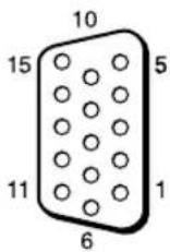
| Pin No. Signal | |
| 1 Red video or C | R/PR |
| 2 Green video or Y | |
| 3 Blue video or C | B/PB |
| 4 Ground | |
| 5 Ground | |
| 6 Red ground | |
| 7 Green ground | |
| 8 Blue ground | |
| 9 Not used | |
| 10 Ground | |
| 11 Ground | |
| 12 SDA | |
| 13 H sync or Composite Video (as sync signal) | |
| 14 V sync | |
| 15 SCL |
Note
When inputting a component signal, be sure not to input sync signals to pins 13 and 14. If you do so, the picture may not be displayed properly.
Index
Numerics
4:3 15, 25
A
ACINsocket11,19
Adjust Screen 21, 25
Advanced Setup 21, 26
All Resct 21, 29
Arrow button 13
Aspect 21, 25
AUDIO IN jack 11
AUDIO jack 11
Auto Adjustment 25
Auto Device Off 29
Auto Display On 29
Auto Screen Adjust 27
Auto Shut Off 27
B
Backlight 22
Balance 23
Bass 23
Brightness 22
Brightness Boost 23
C
Cable holder 20
Chroma 22
CineMotion 22
Clock Display 26
Clock Set 26
Color Temp. 23
Conference 22
Contrast 22
Contrast button 14
Control Mode 26
CONTROL S OUT jack 11
Control Setting 26
Cursor button 11
Custom 22, 23
D
DISPLAY button 14
DVI button 13
DVI connector 11
DVI IN connector 11
Dynamic 23
E
ECOMode21,26
Enter button 11, 13
F
Full 15, 25
Full 1 15, 25
Full 2 15, 25
G
Gamma Correct. 22
H
H Shift 25
H Size 25
HD15 (RGB/COMPONENT)
connector 11
HD15 (RGB/COMPONENT) IN
connector 11
HD15 button 14
HDMI Control 28
1
ID MODE buttons 14, 16
Index Number 14, 16, 26
Information 21, 29
INPUT button 11
Input signal 34
IP Address Setup 28
L
Language 21, 26
LED 24
M
Main power switch 11
MENUButton11,13
Menu Position 28
Multi Display 21, 24
Muting button 14
N
Noise Reduction 22
0
On/Off Timer 26
On-Screen Logo 28
OPTION 1 button 14
OPTION slot 12
Output Format24
Overscan 27
P
Phase 25
PICTURE button 13
Picture Mode 21, 22
Picture Mode Adjust. 21, 22
Picture/Sound Settings 21, 22
Pitch 25
Position 24
Power button 11
Power on button 13
Power On Delay 28
Power/Stand by indicator 9
R
Real 15, 25
REMOTE connector 11
Remote control sensor 9
Reset 23, 25
Return button 11
RGB Signal 28
RGB/YUV 27
S
Screen Saver 28
Screen Settings 21, 24
Setup Settings 21, 26
Sharpness 22
Sound Mode 21, 23
Sound Mode Adjust. 21, 23
Speaker Out 21, 26
SPEAKER socket 11
Speed Setup 28
Standard 22, 23
STANDBY button 14
Status Display 21, 26
Surround 23
Sync Mode 27
T
Tiles 24
Timer Setting 21, 26
Treble 23
V
V Shift 25
V Size 25
Vivid 22
Volume button 11, 14
W
Wide Mode 15
Wide Mode button 13, 15
WideZoom15,25
Window 24
Z
Zoom 15, 25
AVENTISSEMENT
Tbuche ON (alimentation)
7 Touches ID MODE (ON/0-9/SET/C/OFF)
Supports de cables (9)
UL), FCC Class B, IC Class B, EN
60950-1 (NEMKO), CE, C-Tick
Affichage multiple 19, 22
Réglage mode image 19, 20
Touche Mode cinema 11, 13
Touche OPTION 1 12
Touche PICTURE 11
Touche STANDBY 12
Touches ID MODE 12, 14
Tasten ID MODE (ON/0-9/SET/C/OFF)
HD15 (RGB/COMPONENT) IN,
Anschluss 10
HD15 (RGB/COMPONENT),
Anschluss 10
HD15,Taste 12
HDMI-Steuerung 27
Helligkeit 20
Multi-Display 19, 22
N
Netzschalter 9
0
On-Screen Logo 26
OPTION 1, Taste 12
7Botones ID MODE (ON/0-9/SET/C/OFF)
Pantalla multiple 19, 22
Pantalla reloj 24
Personalizzato20,21
Portable 18
Pos. horizontal 23
Pos. vertical 23
Posicón 22
Tasti ID MODE (ON/0-9/SET/C/OFF)
| Risoluzione | Ingressi disponibili | ||||
| Componente | DVI | HDMI | SDI | ||
| 1 | 480/60i | Og | Og | ||
| 2 | 480/60p | Og | Og | Og | |
| 3 | 575/50i | Og | Og | ||
| 4 | 576/50p | Og | Og | Og | |
| 5 | 720/50p | Og | Og | Og | Og |
| 6 | 720/60p | Og | Og | Og | Og |
| 7 | 1080/50i | Og | Og | Og | Og |
| 8 | 1080/60i | Og | Og | Og | Og |
| 9 | 1080/50p | Og | |||
| 10 | 1080/60p | Og | |||
| 11 | 1080/24PsF | Og | |||
UL), FCC Class B, IC Class B, EN
60950-1 (NEMKO), CE, C-Tick
7ID MODE (ON/O-9/SET/C/OFF) 按钮
(c-UL), FCC Class B, IC Class B,
Adjust Screen 16, 20
Advanced Setup 16, 21
A11 Resct 16,23
Aspect 16, 20
AUDIO IN插孔8
AUDIO插孔8
Auto Adjustment 20
Auto Device Off 23
Auto Display On 23
Auto Screen Adjust 22
Auto Shut Off 22
B
Backlight 17
Balance 18
Bass 18
Brightness 17
Brightness Boost 18
C
Chroma 17
CineMotion 17
Clock Display 21
Clock Set 21
Color Temp. 17
Conference 17
Contrast 17
Control Mode 21
CONTROL S OUT 插孔 8
Control Setting 21
Custom 17, 18
D
打开电源按钮9
电缆夹15
电源按钮8
电源/待机指示灯6
DISPLAY按钮10
对比度按钮10
DVI IN 连接器 8
DV1 按钮9
DVI 连接器 8
Dynamic 18
E
EC0 Modc 16, 21
F
返回按钮8
Full 11, 20
Full 1 11, 20
Full 211, 20
G
Gamma Correct. 17
光标按钮8
H
H Shift 20
H Size 20
HD15(RGB/COMPONENT)连接器8
HD15 (RGB/COMPONENT) IN 连接
器8
HD15按钮10
HDMI Control 23
画面设定16,19
1
ID MODE 按钮 10, 12
Index Number 10, 12, 21
Information 16,23
INPUT按钮8
IP Address Setup 23
J
箭头按钮9
静音按钮10
K
宽模式11
宽模式按钮9,11
L
Language 16, 21
LED 19
M
Menu Position 23
MENUP按钮8,9
Multi Display 16, 19
N
Noise Reduction 17
0
On/Off Timer 21
On-Screen Logo 23
OPTION1按钮10
OPTION插槽8
Output Format 19
Overscan 22
P
Phase 20
Picture Mode 16, 17
Picture Mode Adjust. 16, 17
PICTURE按钮9
Pitch 20
Position 19
Power On Delay 23
R
Real 11, 20
REMOTE 连接器8
Reset 18, 20
RGB Signal 22
RGB/YUV 22
S
Screen Saver 22
Sharpness 17
设置设定16,21
输入信号28
Sound Mode 16, 18
Sound Mode Adjust. 16, 18
Speaker Out 16, 21
SPEAKER插座8
Speed Setup 23
Standard 17, 18
STANDBY 按钮 10
Status Display 16, 21
Surround 18
Sync Mode 22
T
Tiles 19
Timer Setting 16, 21
Treblc 18
图像/声音设定6,17
V
V Shift 20
V Size 20
Vivid 17
W
WideZoom11,20
Window 19
Y
遥控传感器6
音量按钮8,10
7
执行按钮9
主电源开关8
Zoom 11, 20