MX802 - Mixer IBIZA SOUND - Free user manual and instructions
Find the device manual for free MX802 IBIZA SOUND in PDF.
| Brand | Ibiza Sound |
| Model | MX802 |
| Category | Mixing Console |
| Product Type | Analog mixing console with digital effects |
| Power Supply | AC adapter 17V AC |
| Input Channels | 8 channels (mic/line) with 3-band EQ |
| Microphone Inputs | Balanced XLR, sensitivity -80dBu to +4dBu |
| Line Inputs | 6.35mm stereo jack, sensitivity -54dBu to +30dBu |
| Channel Equalizer | HIGH (12 kHz), MID (2.5 kHz), LOW (80 Hz), ±15 dB |
| Main Graphic Equalizer | 7 bands (125 Hz - 8 kHz), ±12 dB |
| Internal Effects | Digital effects processor with Delay and Repeat control |
| Media Player | USB (MP3, WMA) and Bluetooth |
| Main Outputs | Balanced XLR and stereo jack, level +4dBu |
| Headphone Output | 6.35mm stereo jack, 75mW |
| Phantom Power | Switchable +48V for condenser microphones |
| Additional Functions | PFL, Mute, AUX bus, RETURN, REC OUT RCA |
| Safety Instructions | Do not open the casing, avoid humidity, disconnect before cleaning |
| Maintenance and Cleaning | Soft damp cloth, do not let water enter |
| Spare Parts and Repairability | Repairs by qualified technician, parts conforming to originals |
Frequently Asked Questions - MX802 IBIZA SOUND
User questions about MX802 IBIZA SOUND
0 question about this device. Answer the ones you know or ask your own.
Ask a new question about this device
Download the instructions for your Mixer in PDF format for free! Find your manual MX802 - IBIZA SOUND and take your electronic device back in hand. On this page are published all the documents necessary for the use of your device. MX802 by IBIZA SOUND.
USER MANUAL MX802 IBIZA SOUND
IMPORTANT SAFETY INSTRUCTIONS
1) Read the manual prior to using this unit and keep it for future reference.
2) Adhere to all warnings and instructions marked on the unit and contained in the manual.
3) Don't place the unit close to water, e.g. in a bathroom, near a wash tub, a swimming pool, etc.
4) The unit must match carriage and rack recommended by the manufacturer. Sudden stops, great power and rough surface may cause combination turns over.
5) Keep away from heat sources such as radiator, stove and amplifier etc.
6) Operate the unit only with the rated power supply. Please ask your dealer or local power supply company if you are not sure about your type of power supply. If the unit is operated with batteries or other power supplies, please refer to this booklet.
7) Connection to ground or polarization: If the unit is fitted with a polarized AC plug, there is only one method to insert the plug. This is a safety characteristic.
8) Do not walk on or squeeze the power cord.
9) Clean this unit with a soft cloth. Prevent water and/or other liquids to enter into the housing.
10) Unplug the power cord if the unit is not used for a long time or during a thunderstorm to prevent voltage surges to damage the inner circuitry.
11) Prevent objects and liquids to enter into unit.
12) If one of the following happens, refer to qualified service personnel:
A) Power cord or plug a damaged; or
B) An object or liquid has entered into the unit; or
C) The unit has been exposed to rain; or
D) The unit doesn't work; or
E) The unit has fallen or doesn't work normally.
13) Repair --Do not attempt to repair the unit yourself. All repairs must be carried out by a qualified technician. The user is only allowed to perform manipulations, settings and controls specified in this manual.
14) Ventilation --- Do not cover the ventilation openings to prevent overheating of the unit. Do not place the unit on bed, blanket, sofa or similar soft surface. Do not place unit inside a bookcase, a closed cupboard, etc.
15) Accessories---Not use parts that hare not recommended by the manufacturer in order to avoid damage.
16) Auxiliary equipment ---Do not place this unit on unstable vehicle, shelf, tripod or table. It will cause serious harm to child or adult if the unit falls down. Please use the vehicle, shelf, tripod or table recommended by the manufacturer.
17) Spare parts---If the unit requires spare parts, use only spares recommended by the manufacturer and that are in all aspects identical to the original parts.
18) Safety check---After repairing, repairer must test the unit for security.
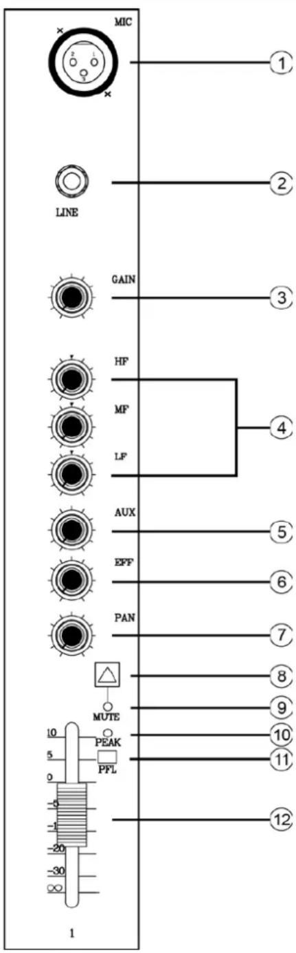
MIC input jack
Balanced XLR microphone input jacks (1: ground; 2: hot; 3: cold)
② LINE input jacks
Balanced TRS phone jacks (T: hot; R: cold; S: Ground)
You can connect either balanced or unbalanced Jack plugs to this socket.
③ GAIN control
Adjustment of the input signal level. To get the best balance between the S/N ratio and the dynamic range, adjust the input signal level so that the PEAK indicator (10) comes on just as the signal approaches its maximum level.
④ Equalizer (HIGH, MID & LOW)
This 3-band EQ adjusts the channel's high, mid and low frequency bands. The stereo channel has a 2-frequency band: HIGH & LOW. Setting the knob to the "▼" position produces a flat frequency response in the corresponding band. Turning the knob to the right boosts the corresponding frequency band, while turning to the left attenuates the band. The following table shows the EQ type, frequency and maximum cut/boost for each of the three bands.
| Band | Type | Frequency | Max. Cut/Boost |
| HIGH | Shelving | 12kHz | |
| MID | Peaking | 2.5kHz | ± 15dB |
| LOW | Shelving | 80Hz |
(5) AUX Control
These knobs adjust the channel's signal levels into AUX BUSES.
⑥ EFFECT Control
Adjusts the level of the signal sent from the channel to the EFFECT bus. Note that the signal level sent to the bus is also affected by the channel fader.
⑦ PAN control
The PAN control determines the stereo positioning of the channel signal on the STEREOL & R buses.
MUTE Switch
When depressed, this switch mutes the signal of the channel to all outputs.
MUTE Indicator
Press MUTE switch and the indicator lights up in red.
10 PEAK indicator
The peak level of the post -EQ signal is detected and the PEAK indicator light yellow when the level reaches 3dB below clipping.
PFL switch
Depress this switch to feed to the channels pre-channel fader signal into the PFL bus, so that you can monitor the signal from the PHONES jack. To turn PFL feed on, press the switch in so that it lights up.
② Channel Fader Control
Adjusts the output level of the channel signal. Use these faders to adjust the balance between the various channels.
NOTE: Set the faders for unused channels all the way down to minimize noise.
MASTER CONTROL SECTION:
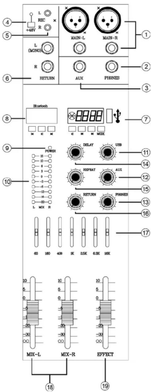
① MAIN OUT (L, R) jacks
These jacks send the mixer's stereo output. E.g. you can connect these jacks to a power amplifier driving the main speaker. When you record the mixer's stereo output using the MAIN OUT Master fader to control the level, you can also connect these jacks to the recording device.
② PHONES Jacks
Connect a pair of headphones to this stereo phone jack.
③ AUXJack
The Jack output is driven by the setting of the AUX control (5) of every channel. You can use the jack to connect to an effect unit, video filter or other monitor system.
(4)PHANTOM +48V switch
This switch toggles phantom power on and off. When the switch is on, the mixer supplies +48V phantom power to all channels that have XLR mic input jacks. Turn this switch to on when using one or more phantom-powered condenser microphones
NOTE: When this switch is on, the mixer supplies DC +48V power to pin 2 and 3 of all XLR type MIC INPUT jacks.
CAUTION: Be sure to leave this switch OFF if you don't need phantom power.
When turning the switch to ON, be sure that only condenser microphones are connected to the XLR input jacks. Devices other than condenser mics may be damaged if connected to the phantom power supply. Please note however that the switch may be left on when connecting to balanced dynamic microphones.
To prevent damage to speakers, be sure to turn off power amplifiers (or powered speakers) before turning this switch on or off. We also recommend that you turn all output controls (stereo out, Master fader, GROUP 1-2 fader, GROUP 3-4 fader, etc) to their minimum settings before operating the switch to avoid the risk of loud noises that could cause hearing loss or device damage.
⑤ REC output (L, R) Jacks
You can connect these unbalanced RCA pin jacks to an external recorder to record the signal output from the ST OUT jacks. Please note: The mixer's STEREO OUT main fader doesn't affect the output signal of these jacks. Adjust the level as necessary at the external recording device.
RETURN L (MONO) R Jack
These are unbalanced phone input jacks. The signal into each of these jacks feeds into the STEREO L/R bus and AUX1 and AUX2 buses. The stereo signal was returned, the single mix of signal was send into AUX1
and AUX2 buses. These jacks are typically used to receive a return signal from an external effect unit (reverb, delay, etc.).
Please note: These jacks can also be used as an auxiliary stereo input. If you connect to the L (MONO) jack only, the mixer will recognize the signal as monaural and will propagate the identical signal from both L and R jacks.
⑦ Music Player
Insert a USB stick into the USB socket (7) to activate the music player. The unit supports MP3, WMA files.
The player offers a Bluetooth and recording function. Select the mode via the MODE button.
⑧ BLUETOOTH
Press the MP3 MODE switch to select Bluetooth mode.
⑨ POWER indicator
This indicator lights when the mixer's power is ON.
10 Level Meter
This LED meter displays the level of the signal output from the MAIN and the PHONES. When the LED is OFF, it shows MAIN level, when the LED is ON, it shows PHONES level.
11 USB control
Adjusts the signal level to MAIN bus.
12 AUX Control
Adjusts the output volume of the signal from the AUX socket (3)
13 PHONES Control
Adjusts the output level of PHONES jack (2).
⑭ Delay Control
Adjusts the delay time of the internal effect unit.
15 REPEAT Control
Adjusts the depth of the internal digital effects.
16 RETURN control
Adjusts the signal level from the RETURN socket to the MAIN bus.
⑦ MAIN GRAPHIC EQUALIZER
This 7-band EQ adjusts the sound signal sent to the MAIN OUT jack. The EQ cuts or boosts all frequency bands (125Hz / 250Hz / 500Hz / 1kHz / 2kHz / 4kHz / 8kHz) within the range of ± 12dB .
18 MIX L/R
Adjusts the output level of MAIN socket.
19 EFFECT Fader Control
Adjusts the signal level of internal effects to the MAIN bus.
REAR PANEL:
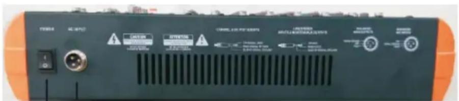
① POWER
17V AC power input: Properly insert the power adaptor (supplied).
② Power switch
QUICK GUIDE
-
Be sure that your mixer is turned off and that all level controls* are turned all the way down.
-
STEREO OUT Master fader, Channel faders, GROUP 1-2 faders, GAIN controls, etc.
Note: Set the equalizer and the PAN controls to their positions.
- Turn off any other external devices, and then connect microphones, instruments and speakers.
Note: Connect electric guitars and basses through an intermediary device such as a direct box, preamp, or amp simulator. Connecting these instruments directly to the professional audio mixer may result in degraded sound and noise.
- To avoid damage to your speakers, power up the devices in the following order: Peripheral devices professional audio mixer power amps or powered speakers). Reverse this order when turning power off.
NOTE: If you are using condenser microphones that require phantom power, turn the professional audio mixer's phantom power switch on before turning on the power to the power amp or powered speakers.
- Adjust the channel GAIN controls so that the corresponding PEAK indicators flash briefly on the highest peak levels.
Note: Turn the channel PFL switch on if you want to get an accurate reading of the incoming signal level using the level meter. Adjust the GAIN controls so that the level meter indication occasionally rises above the "▼" (0) level.
Note that PHONES jacks output pre-fader signals from all channels with their PFL switches set to the ON position so that these signals can be monitored via the headphones.
-
Set the STEREO OUT Master fader to the "0" position.
-
Set the Channel faders to create the desired initial balance, then adjust the overall volume using the STEREO OUT Master fader.
NOTE: * To use the level meter to view the level being applied to the STEREO L/R buses, set the PFL switch off ( )
- If the PEAK indicator lights frequently, lower the Channel faders a little to avoid distortion
SPECIFICATIONS
Input Specifications
| Input connectors | Gain | Input impedance | Appropriate impedance | Sensitivity | Nominal level | Max. before clipping | Connector specifications |
| CH INPUT MIC | -60dB | 3kΩ | 50-600Ω Mics | -80dBu (0.078mV) | -60dBu (0.775mV) | -40dBu (7.75mV) | Bal. XLR (1=Gnd; 2=Hot; 3=Cold) |
| -16dB | -36 dBu (12.3mV) | -16 dBu (123mV) | +4 dBu (1.23V) | ||||
| CH INPUT LINE | -34dB | 10kΩ 600Ω | Line | -54 dBu (1.55mV) | -34 dBu (15.5mV) | -14 dBu (155mV) | Bal. TRS Jack (Tip=Hot; Ring=Cold; Sleeve=Gnd) |
| +10dB | -10 dBu (245mV) | +10 dBu (2.45V) | +30 dBu (24.5V) | ||||
| RETURN L/R | - | 10kΩ | 600Ω Line | -12 dBu (195mV) | +4 dBu (1.23V) | +24 dBu (12.3V) | Unbal. Jack |
| 2TR IN (L/R) | - | 10kΩ | 600Ω Line | -26 dBV (50.1mV) | -10 dBV (0.316V) | +10 dBV (3.16V) | RCA |
Output Specifications
| Output connectors | Gain | Appropriate impedance | Nominal level | Max. before clipping | Connector specifications |
| MAIN OUT (L / R) | 75Ω | 600Ω Line | +4dBu (1.23V) | +24 dBu (1.23V) | Bal. XLR (1=Gnd; 2=Hot; 3=Cold) Bal. TRS Jack (Tip=Hot; Ring=Cold; Sleeve=Gnd) |
| EFFECT/AUX (AUX1/2) SEND | 150Ω | 10kΩ Line | +4 dBu (1.23V) | +20 dBu (7.75V) | Bal. TRS Jack (Tip=Hot; Ring=Cold; Sleeve=Gnd) |
| REC OUT L/R | 600Ω | 10kΩ Line | -10 dBV (0.316V) | +10 dBV (3.16V) | RCA |
| PHONES OUT | 100Ω | 40Ω Phones | 3mW | 75mW | Stereo Jack |
JACK LIST
| In & output jacks | Polarities | Configuration |
| MIC INPUT, STEREO OUT | Pin 1: Ground | INPUT OUTPUT |
| Pin 2: Hot (+) | XLR Jack | |
| Pin 3: Cold (-) | ||
| input/output | ||
| LINE INPUT (monaural channels) GROUP OUT, STEREO OUT, MONITOR OUT, AUX SEND, EFFECT SEND | Tip: Hot (+) | Ring |
| Ring: Cold (-) | ||
| Sleeve: Ground | ||
| INSERT | Tip: Output | Sleeve Tip TRS Phone Jack |
| Ring: Input | ||
| Sleeve: Ground | ||
| PHONES | Tip: L | Sleeve Tip Phone Jack |
| Ring: R | ||
| Sleeve: Ground | ||
| RETURN LINE INPUT (stereo channels) | Tip: Hot | |
| Sleeve: Ground |
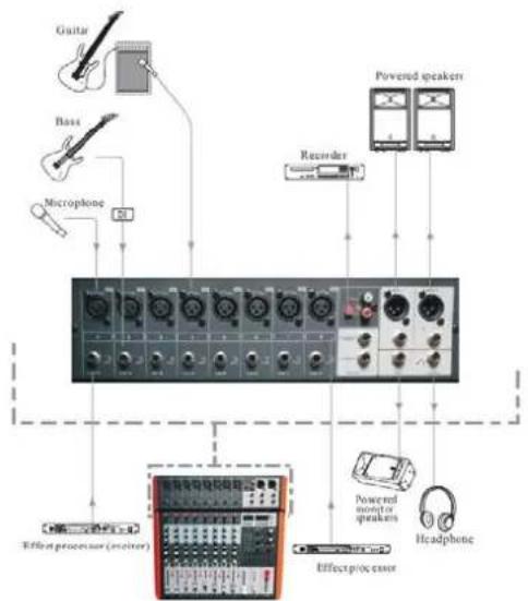
WIRING DIAGRAM

Electric products must not be put into household waste. Please bring them to a recycling centre. Ask your local authorities or your dealer about the way to proceed.

| Band | Type | Frequency | Max. Cut/Boost |
| HIGH | Shelving | 12kHz | |
| MID | Peaking | 2.5kHz | ± 15dB |
| LOW | Shelving | 80Hz |
(5) AUX Regler
⑤ Salida REC (G / D)
② Interruptor ON/OFF
GUIA RAPIDA
Balansiran Jack vhod (T: hot; R: cold; S: Ground)
Lahko prikljucite bodisi simetrično ali asimetrično Jack vtikače na to vtičnico.
(3) GAIN kontrola
Shock hazard - Do not open the housing