MX401 - Mixer IBIZA SOUND - Free user manual and instructions
Find the device manual for free MX401 IBIZA SOUND in PDF.
| Product type | Mixing table |
| Brand | Ibiza Sound |
| Model | MX401 |
| Number of input channels | 4 mono channels (MIC/LINE) + 2 stereo channels (LINE/USB) |
| Microphone inputs | 4 x balanced XLR with phantom power +48V |
| Line inputs | 4 x 6.35 mm jacks (mono) + 2 pairs of 6.35 mm stereo jacks |
| Main outputs | 2 x XLR (Main Out L/R) |
| Headphone outputs | 2 x 6.35 mm stereo jacks (PHONES A and B) |
| Per channel EQ | 3 bands (HIGH: 12 kHz, MID: 2.5 kHz, LOW: 80 Hz) ±15 dB |
| Main graphic equalizer | 5 bands (100 Hz, 400 Hz, 1 kHz, 3 kHz, 8 kHz) ±12 dB |
| Effects processor | Built-in digital with tempo and repeat control |
| Phantom power | +48 V switchable for all XLR inputs |
| USB player | Yes, MP3/WMA compatible |
| Power supply | AC adapter included, selectable voltage |
| Level indicator | LED VU meter for MAIN and PHONES outputs |
| Care and cleaning | Unplug before cleaning; use a soft, damp cloth |
| Safety | Do not open the casing; repairs by qualified technician |
| Spare parts | Use only approved parts conforming to original ones |
Frequently Asked Questions - MX401 IBIZA SOUND
User questions about MX401 IBIZA SOUND
0 question about this device. Answer the ones you know or ask your own.
Ask a new question about this device
Download the instructions for your Mixer in PDF format for free! Find your manual MX401 - IBIZA SOUND and take your electronic device back in hand. On this page are published all the documents necessary for the use of your device. MX401 by IBIZA SOUND.
USER MANUAL MX401 IBIZA SOUND
Read all documentations carefully before operating the equipment. Retain this manual for future reference. Follow all instructions printed on unit for proper operation.

Do not open cover (or back cover) to reduce the risk of electric shock or fire. There are no user serviceable parts inside. Refer servicing to qualified service Personnel.

This symbol is used to alert the operator to the presence of important operating instructions and precautions detailed in the documentation manual.

This symbol is used to warn operators that uninsulated dangerous voltages are present within the products enclosure that may pose a risk of electric shock.
Warning: To avoid fire or risk of electric shock, do not expose this unit to rain or moisture.
Notes:
- Make sure power outlets conform to the power requirements listed on the back of the unit.
- Main voltage must be correct and the same as that printed on the rear of the unit.
- Do not use the unit if the electrical cord is frayed or broken.
- The unit shall not be exposed to dripping or splashing and that no objects filled with liquids, such as vases, shall be placed on unit.
- The unit shall be connected to a mains socket outlet with a protective earthing connection.
- Power plug as a equipment that separate from power supply system, it must be easy to operating.
Warning:
- Using, adjusting or changing program control beyond this specification may cause dangerous radiation.
- The unit should be serviced by qualified service personnel.
- When repairing, use only same specification parts.
Notes:
- Select the voltage requirement through the voltage selector switch at the real panel.
- Make sure that the power of the equipment is off and disconnected from the main voltage before switching the voltage selector to the required setting. We will not be responsible for damages arising from the improper installation, wiring or operation due to the fault or negligence of the user.
IMPORTANT SAFETY INSTRUCTIONS
1) Read the manual prior to using this unit and keep it for future reference.
2) Adhere to all warnings and instructions marked on the unit and contained in the manual.
3) Don't place the unit close to water, e.g. in a bathroom, near a wash tub, a swimming pool, etc.
4) The unit must match carriage and rack recommended by the manufacturer. Sudden stops, great power and rough surface may cause combination turns over.
5) Keep away from heat sources such as radiator, stove and amplifier etc.
6) Operate the unit only with the rated power supply. Please ask your dealer or local power supply company if you are not sure about your type of power supply. If the unit is operated with batteries or
other power supplies, please refer to this booklet.
7) Connection to ground or polarization: If the unit is fitted with a polarized AC plug, there is only one method to insert the plug. This is a safety characteristic.
8) Do not walk on or squeeze the power cord.
9) Clean this unit with a soft cloth. Prevent water and/or other liquids to enter into the housing.
10) Unplug the power cord if the unit is not used for a long time or during a thunderstorm to prevent voltage surges to damage the inner circuitry.
11) Prevent objects and liquids to enter into unit.
12) If one of the following happens, refer to qualified service personnel:
A) Power cord or plug a damaged; or
B) An object or liquid has entered into the unit; or
C) The unit has been exposed to rain; or
D) The unit doesn't work; or
E) The unit has fallen or doesn't work normally.
13) Repair ---Do not attempt to repair the unit yourself. All repairs must be carried out by a qualified technician. The user is only allowed to perform manipulations, settings and controls specified in this manual.
14) Ventilation --- Do not cover the ventilation openings to prevent overheating of the unit. Do not place the unit on bed, blanket, sofa or similar soft surface. Do not place unit inside a bookcase, a closed cupboard, etc.
15) Accessories---Not use parts that hare not recommended by the manufacturer in order to avoid damage.
16) Auxiliary equipment --Do not place this unit on unstable vehicle, shelf, tripod or table. It will cause serious harm to child or adult if the unit falls down. Please use the vehicle, shelf, tripod or table recommended by the manufacturer.
17) Spare parts--If the unit requires spare parts, use only spares recommended by the manufacturer and that are in all aspects identical to the original parts.
18) Safety check---After repairing, repairer must test the unit for security.
CHANNEL CONTROL SECTION:
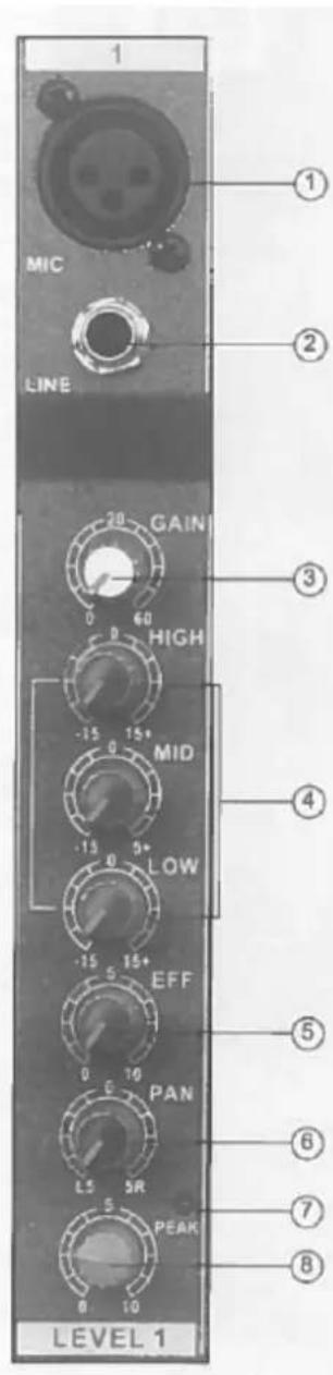
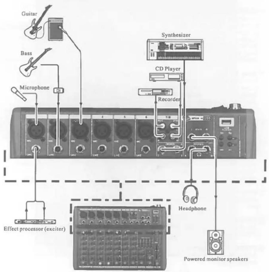
MIC input jack
Balanced XLR microphone input jacks (1: ground; 2: hot; 3: cold)
② LINE input jacks
Balanced TRS phone jacks (T: hot; R: cold; S: Ground)
You can connect either balanced or unbalanced Jack plugs to this socket.
③ GAIN control
Adjustment of the input signal level. To get the best balance between the S/N ratio and the dynamic range, adjust the input signal level so that the PEAK indicator lights occasionally and briefly only on the highest input transients.
④ Equalizer (HIGH, MID & LOW)
This 3-band EQ adjusts the channel's high, mid and low frequency bands. The stereo channel has a 2-frequency band: HIGH & LOW. Setting the knob to the "▼" position produces a flat frequency response in the corresponding band. Turning the knob to the right boosts the corresponding frequency band, while turning to the left attenuates the band. The following table shows the EQ type, frequency and maximum cut/boost for each of the three bands.
| Band | Type | Frequency | Max. Cut/Boost |
| HIGH | Shelving | 12kHz | |
| MID | Peaking | 2.5kHz | ± 15dB |
| LOW | Shelving | 80Hz |
⑤ EFFECT Control
Adjusts the level of the signal sent from the channel to the EFFECT bus. Note that the signal level sent to the bus is also affected by the channel fader.
⑥ PAN control
The PAN control determines the stereo positioning of the channel signal on
theSTEREO L & R buses.
⑦ PEAK indicator
The peak level of the post-EQ signal is detected and the PEAK indicator light yellow when the level reaches 3dB below clipping.
⑧ Channel Fader Control
Adjusts the level of the channel signal. Use these faders to adjust the balance between the various channels.
NOTE: Set the faders for unused channels all the way down to minimize noise.

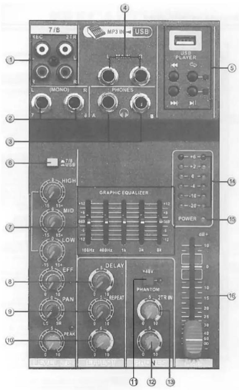
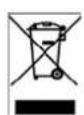
MASTER CONTROL SECTION:
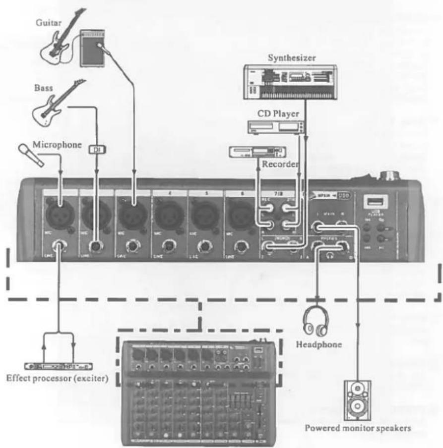
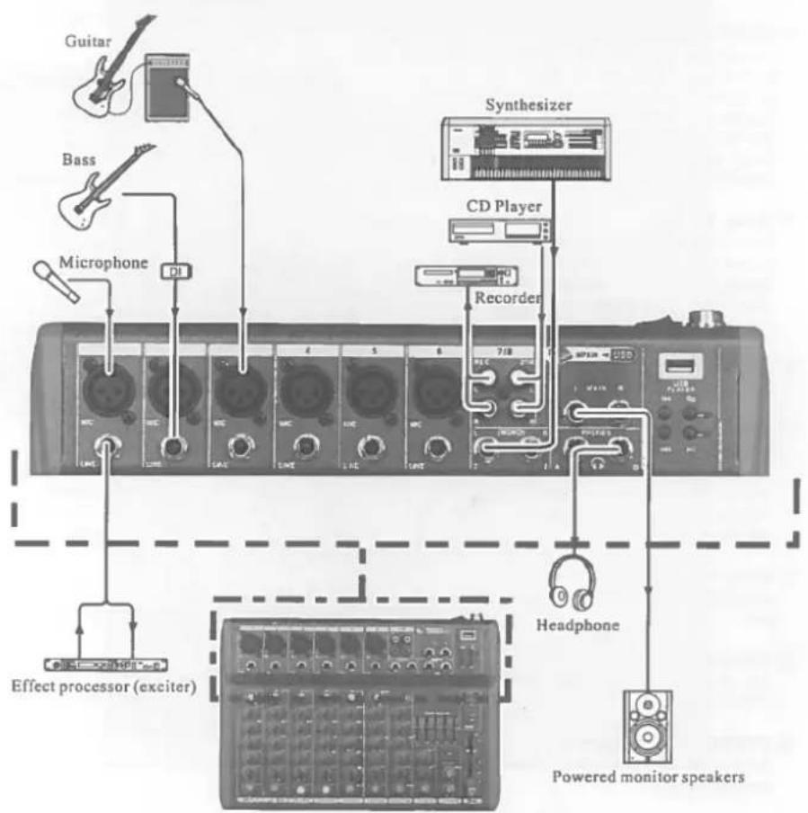
1 REC (output) / 2TR (input) (L, R) Jacks You can connect these RCA pin jacks to an external recorder such as an MD recorder to record the signal output from the MAIN OUT jacks. Connect 2TR to send the signal to MAIN.
② LINE input jacks (stereo channel)
These are unbalanced phone jack type stereo line inputs.
③ PHONES Jacks
Connect a pair of headphones to this stereo phone jack. There are 2x Jacks: A & B.
(4) MAIN OUT (L, R) jacks
These jacks send the mixer's stereo output. E.g. you can connect these jacks to a power amplifier driving the main speaker. When you record the mixer's stereo output using the MAIN OUT Master fader to control the level, you can also connect these jacks to the recording device.
⑤ Music Player
This is a high sound quality music player. Insert the USB device containing the MP3, WMA music files into the USB port and play the music via the stereo channel (USB select switch).
(6) (1)% (7 / 8)() USB Select switch
Stereo channel signal selector switch.
⑦ MAIN GRAPHIC EQUALIZER
This 5-band EQ adjusts the sound signal from the MAIN OUT jack. The EQ cuts or boosts all frequency bands (100Hz / 400Hz / 1kHz / 3kHz / 8kHz) within the range of ±12dB.
⑧ Delay Control
Adjusts the delay time of the internal effect unit.
⑨ REPEAT Control
Adjusts the depth of the internal digital effects.
⑩ EFFECT Fader Control
Adjusts the signal level of internal effects to the MAIN bus.
1) PHANTOM +48V switch
This switch toggles phantom power on and off. When the switch is on, the mixer supplies +48V phantom power to all channels that have XLR mic input jacks. Turn this switch to on when using one or more phantom-powered condenser microphones
NOTE: When this switch is on, the mixer supplies DC +48V power to pin 2 and 3 of all XLR type MIC INPUT jacks.
CAUTION: Be sure to leave this switch OFF if you don't need phantom power.
When turning the switch to ON, be sure that only condenser microphones are connected to the XLR input jacks. Devices other than condenser mics may be damaged if connected to the phantom power supply. Please note however that the switch may be left on when connecting to balanced dynamic microphones. To prevent damage to speakers, be sure to turn off power amplifiers (or powered speakers) before turning this switch on or off. We also recommend that you turn all output controls (stereo out, Master fader, GROUP 1-2 fader, GROUP 3-4 fader, etc) to their minimum settings before operating the switch to avoid the risk of loud noises that could cause hearing loss or device damage.
12 PHONES Control
Adjusts output level of jacks (4).
(13) 2TR IN (TAPE)
Adjusts the input signal of TAPE to MAIN.
14 Level Meter
This LED meter displays the level of the signal output from the MAIN and the PHONES.
⑤ POWER indicator
This indicator lights when the mixer's power is ON.
16 MAIN OUT Master Fader
Adjusts the signal level sent to the MAIN OUT jack.
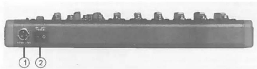
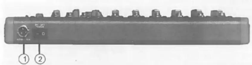
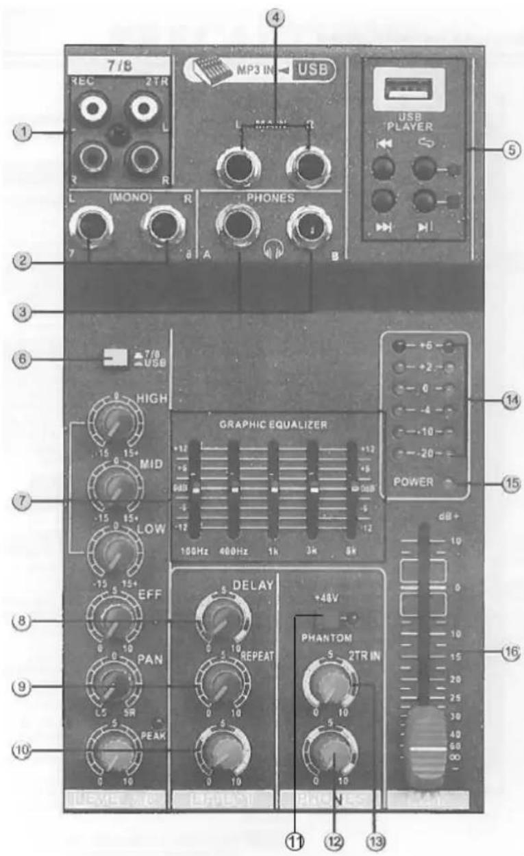
REAR PANEL:

① POWER
AC power input: Properly insert the power adaptor (supplied).
② Power switch
JACK LIST
| In & output jacks | Polarities | Configuration |
| MIC INPUT, STEREO OUT | Pin 1: Ground | INPUT OUTPUT |
| Pin 2: Hot (+) | ||
| Pin 3: Cold (-) | ||
| input/output | XLR Jack | |
| LINE INPUT (monaural channels) GROUP OUT, STEREO OUT, MONITOR OUT, AUX SEND, EFFECT SEND | Tip: Hot (+) | Ring |
| Ring: Cold (-) | ||
| Sleeve: Ground | ||
| INSERT | Tip: Output | Sleeve Tip TRS Phone Jack |
| Ring: Input | ||
| Sleeve: Ground | ||
| PHONES | Tip: L | |
| Ring: R | ||
| Sleeve: Ground | ||
| RETURN LINE INPUT (stereo channels) | Tip: Hot | Sleeve Tip Phone Jack |
| Sleeve: Ground |
⑧ Temporisation (Delay)
Fader general MAIN OUT
16 MAIN OUT Master Fader
Balanced XLR microphone input jacks (1: ground; 2: hot; 3: cold)
② LINE input jacks
Balanced TRS phone jacks (T: hot; R: cold; S: Ground)
You can connect either balanced or unbalanced Jack plugs to this socket.
③ GAIN control
Adjustment of the input signal level. To get the best balance between the S/N ratio and the dynamic range, adjust the input signal level so that the PEAK indicator lights occasionally and briefly only on the highest input transients.
④ Equalizer (HIGH, MID & LOW)
This 3-band EQ adjusts the channel's high, mid and low frequency bands. The stereo channel has a 2-frequency band: HIGH & LOW. Setting the knob to the "▼" position produces a flat frequency response in the corresponding band. Turning the knob to the right boosts the corresponding frequency band, while turning to the left attenuates the band. The following table shows the EQ type, frequency and maximum cut/boost for each of the three bands.
| Band | Type | Frequency | Max. Cut/Boost |
| HIGH | Shelving | 12kHz | ± 15dB |
| MID | Peaking | 2.5kHz | |
| LOW | Shelving | 80Hz |
⑤ EFFECT Control
Adjusts the level of the signal sent from the channel to the EFFECT bus. Note that the signal level sent to the bus is also affected by the channel fader.
⑥ PAN control
The PAN control determines the stereo positioning of the channel signal on
theSTEREO L & R buses.
⑦ PEAK indicator
The peak level of the post -EQ signal is detected and the PEAK indicator light yellow when the level reaches 3dB below clipping.
⑧ Channel Fader Control
Adjusts the level of the channel signal. Use these faders to adjust the balance between the various channels.
NOTE: Set the faders for unused channels all the way down to minimize noise.
MASTER CONTROL SECTION:
① TAPE OUT IN (L, R) Jacks
You can connect these RCA pin jacks to an external recorder such as an MD recorder to record the signal output from the MAIN OUT jacks. Connect IN to send the signal to MAIN.
② LINE input jacks (stereo channel)
These are unbalanced phone jack type stereo line inputs.
③ PHONES Jacks
Connect a pair of headphones to this stereo phone jack. There are 2x Jacks: A & B.
(4) MAIN OUT (L, R) jacks
These jacks send the mixer's stereo output. E.g. you can connect these jacks to a power amplifier driving the main speaker. When you record the mixer's stereo output using the MAIN OUT Master fader to control the level, you can also connect these jacks to the recording device.
(5) Music Player
This is a high sound quality music player. Insert the USB device containing the MP3, WMA music files into the USB port and play the music via the stereo channel (USB select switch).
(6) (I) 3/4 (7/8) (·) USB Select switch
Stereo channel signal selector switch.
⑦ MAIN GRAPHIC EQUALIZER
This 5-band EQ adjusts the sound signal from the MAIN OUT jack. The EQ cuts or boosts all frequency bands (100Hz / 400Hz / 1kHz / 3kHz / 8kHz) within the range of ±12dB.
⑧ Delay Control
Adjusts the delay time of the internal effect unit.
⑨ REPEAT Control
Adjusts the depth of the internal digital effects.
10 EFFECT Fader Control
Adjusts the signal level of internal effects to the MAIN bus.
(1) PHANTOM +48V switch
This switch toggles phantom power on and off. When the switch is on, the mixer supplies +48V phantom power to all channels that have XLR mic input jacks. Turn this switch to on when using one or more phantom-powered condenser microphones
NOTE: When this switch is on, the mixer supplies DC +48V power to pin 2 and 3 of all XLR type MIC INPUT jacks.
CAUTION: Be sure to leave this switch OFF if you don't need phantom power.
When turning the switch to ON, be sure that only condenser microphones are connected to the XLR input jacks. Devices other than condenser mics may be damaged if connected to the phantom power supply. Please note however that the switch may be left on when connecting to balanced dynamic microphones. To prevent damage to speakers, be sure to turn off power amplifiers (or powered speakers) before turning this switch on or off. We also recommend that you turn all output controls (stereo out, Master fader, GROUP 1-2 fader, GROUP 3-4 fader, etc) to their minimum settings before operating the switch to avoid the risk of loud noises that could cause hearing loss or device damage.
(12) PHONES Control
Adjusts output level of jacks (4).
⑬ 2TR IN (TAPE)
Adjusts the input signal of TAPE to MAIN.
14 Level Meter
This LED meter displays the level of the signal output from the MAIN and the PHONES. It displays MAIN level when it doesn't light. It displays PHONES level when it lights.
⑤ POWER indicator
This indicator lights when the mixer's power is ON.
16 MAIN OUT Master Fader
Adjusts the signal level sent to the MAIN OUT jack.
REAR PANEL:
① POWER
AC power input: Properly insert the power adaptor (supplied).
② Power switch
JACK LIST
| In & output jacks | Polarities | Configuration |
| MIC INPUT, STEREO OUT | Pin 1: Ground | INPUT OUTPUT |
| Pin 2: Hot (+) | XLR Jack | |
| Pin 3: Cold (-) | ||
| input/output | ||
| LINE INPUT (monaural channels) GROUP OUT,STEREO OUT, MONITOR OUT, AUX SEND, EFFECTSEND | Tip: Hot (+)Ring: Cold (-)Sleeve: Ground | Ring |
| INSERT | Tip: OutputRing: InputSleeve: Ground | Sleeve Tip TRS Phone Jack |
| PHONES | Tip: LRing: RSleeve: Ground | |
| RETURN LINE INPUT (stereo channels) | Tip: HotSleeve: Ground | Sleeve Tip Phone Jack |

Balanced XLR microphone input jacks (1: ground; 2: hot; 3: cold)
② LINE input jacks
Balanced TRS phone jacks (T: hot; R: cold; S: Ground)
You can connect either balanced or unbalanced Jack plugs to this socket.
③ GAIN control
Adjustment of the input signal level. To get the best balance between the S/N ratio and the dynamic range, adjust the input signal level so that the PEAK indicator lights occasionally and briefly only on the highest input transients.
④ Equalizer (HIGH, MID & LOW)
This 3-band EQ adjusts the channel's high, mid and low frequency bands. The stereo channel has a 2-frequency band: HIGH & LOW. Setting the knob to the "▼" position produces a flat frequency response in the corresponding band. Turning the knob to the right boosts the corresponding frequency band, while turning to the left attenuates the band. The following table shows the EQ type, frequency and maximum cut/boost for each of the three bands.
| Band | Type | Frequency | Max. Cut/Boost |
| HIGH | Shelving | 12kHz | ± 15dB |
| MID | Peaking | 2.5kHz | |
| LOW | Shelving | 80Hz |
⑤ EFFECT Control
Adjusts the level of the signal sent from the channel to the EFFECT bus. Note that the signal level sent to the bus is also affected by the channel fader.
⑥ PAN control
The PAN control determines the stereo positioning of the channel signal on the STEREOL & R buses.
⑦ PEAK indicator
The peak level of the post -EQ signal is detected and the PEAK indicator light yellow when the level reaches 3dB below clipping.
⑧ Channel Fader Control
Adjusts the level of the channel signal. Use these faders to adjust the balance between the various channels.
NOTE: Set the faders for unused channels all the way down to minimize noise.

MASTER CONTROL SECTION:
① TAPE OUT IN (L, R) Jacks
You can connect these RCA pin jacks to an external recorder such as an MD recorder to record the signal output from the MAIN OUT jacks. Connect IN to send the signal to MAIN.
② LINE input jacks (stereo channel)
These are unbalanced phone jack type stereo line inputs.
③ PHONES Jacks
Connect a pair of headphones to this stereo phone jack. There are 2x Jacks: A & B.
(4) MAIN OUT (L, R) jacks
These jacks send the mixer's stereo output. E.g. you can connect these jacks to a power amplifier driving the main speaker. When you record the mixer's stereo output using the MAIN OUT Master fader to control the level, you can also connect these jacks to the recording device.
⑤ Music Player
This is a high sound quality music player. Insert the USB device containing the MP3, WMA music files into the USB port and play the music via the stereo channel (USB select switch).
(6) (1)% (7 / 8)() USB Select switch
Stereo channel signal selector switch.
⑦ MAIN GRAPHIC EQUALIZER
This 5-band EQ adjusts the sound signal from the MAIN OUT jack. The EQ cuts or boosts all frequency bands (100Hz / 400Hz / 1kHz / 3kHz / 8kHz) within the range of ±12dB.
⑧ Delay Control
Adjusts the delay time of the internal effect unit.
⑨ REPEAT Control
Adjusts the depth of the internal digital effects.
10 EFFECT Fader Control
Adjusts the signal level of internal effects to the MAIN bus.
11 PHANTOM +48V switch
This switch toggles phantom power on and off. When the switch is on, the mixer supplies +48V phantom power to all channels that have XLR mic input jacks. Turn this switch to on when using one or more phantom-powered condenser microphones
NOTE: When this switch is on, the mixer supplies DC +48V power to pin 2 and 3 of all XLR type MIC INPUT jacks.
CAUTION: Be sure to leave this switch OFF if you don't need phantom power.
When turning the switch to ON, be sure that only condenser microphones are connected to the XLR input jacks. Devices other than condenser mics may be damaged if connected to the phantom power supply. Please note however that the switch may be left on when connecting to balanced dynamic microphones. To prevent damage to speakers, be sure to turn off power amplifiers (or powered speakers) before turning this switch on or off. We also recommend that you turn all output controls (stereo out, Master fader, GROUP 1-2 fader, GROUP 3-4 fader, etc) to their minimum settings before operating the switch to avoid the risk of loud noises that could cause hearing loss or device damage.
12 PHONES Control
Adjusts output level of jacks (4).
(13) 2TR IN (TAPE)
Adjusts the input signal of TAPE to MAIN.
Level Meter
This LED meter displays the level of the signal output from the MAIN and the PHONES. It displays MAIN level when it doesn't light. It displays PHONES level when it lights.
15 POWER indicator
This indicator lights when the mixer's power is ON.
16 MAIN OUT Master Fader
Adjusts the signal level sent to the MAIN OUT jack.
REAR PANEL:
① POWER
AC power input: Properly insert the power adaptor (supplied).
② Power switch
JACK LIST
| In & output jacks | Polarities | Configuration |
| MIC INPUT, STEREO OUT | Pin 1: Ground | INPUT OUTPUT |
| Pin 2: Hot (+) | ||
| Pin 3: Cold (-) input/output | XLR Jack | |
| LINE INPUT (monaural channels) GROUP OUT, STEREO OUT, MONITOR OUT, AUX SEND, EFFECT SEND | Tip: Hot (+) Ring: Cold (-) Sleeve: Ground | Ring |
| INSERT | Tip: Output Ring: Input Sleeve: Ground | Sleeve Tip TRS Phone Jack |
| PHONES | Tip: L Ring: R Sleeve: Ground | |
| RETURN LINE INPUT (stereo channels) | Tip: Hot Sleeve: Ground | Sleeve Tip Phone Jack |
Balanced XLR microphone input jacks (1: ground; 2: hot; 3: cold)
② LINE input jacks
Balanced TRS phone jacks (T: hot; R: cold; S: Ground)
You can connect either balanced or unbalanced Jack plugs to this socket.
(3) GAIN control
Adjustment of the input signal level. To get the best balance between the S/N ratio and the dynamic range, adjust the input signal level so that the PEAK indicator lights occasionally and briefly only on the highest input transients.
④ Equalizer (HIGH, MID & LOW)
This 3-band EQ adjusts the channel's high, mid and low frequency bands. The stereo channel has a 2-frequency band: HIGH & LOW. Setting the knob to the "▼" position produces a flat frequency response in the corresponding band. Turning the knob to the right boosts the corresponding frequency band, while turning to the left attenuates the band. The following table shows the EQ type, frequency and maximum cut/boost for each of the three bands.
| Band | Type | Frequency | Max. Cut/Boost |
| HIGH | Shelving | 12kHz | ± 15dB |
| MID | Peaking | 2.5kHz | |
| LOW | Shelving | 80Hz |
⑤ EFFECT Control
Adjusts the level of the signal sent from the channel to the EFFECT bus. Note that the signal level sent to the bus is also affected by the channel fader.
(6) PAN control
The PAN control determines the stereo positioning of the channel signal on the STEREO L & R buses.
⑦ PEAK indicator
The peak level of the post -EQ signal is detected and the PEAK indicator light yellow when the level reaches 3dB below clipping.
⑧ Channel Fader Control
Adjusts the level of the channel signal. Use these faders to adjust the balance between the various channels.
NOTE: Set the faders for unused channels all the way down to minimize noise.
① TAPE OUT IN (L, R) Jacks
You can connect these RCA pin jacks to an external recorder such as an MD recorder to record the signal output from the MAIN OUT jacks. Connect IN to send the signal to MAIN.
LINE input jacks (stereo channel)
These are unbalanced phone jack type stereo line inputs.
③ PHONES Jacks
Connect a pair of headphones to this stereo phone jack. There are 2x Jacks: A & B.
(4) MAIN OUT (L, R) jacks
These jacks send the mixer's stereo output. E.g. you can connect these jacks to a power amplifier driving the main speaker. When you record the mixer's stereo output using the MAIN OUT Master fader to control the level, you can also connect these jacks to the recording device.
⑤ Music Player
This is a high sound quality music player. Insert the USB device containing the MP3, WMA music files into the USB port and play the music via the stereo channel (USB select switch).
(6) (I) 3 / 4 (7/8) (·) USB Select switch
Stereo channel signal selector switch.
⑦ MAIN GRAPHIC EQUALIZER
This 5-band EQ adjusts the sound signal from the MAIN OUT jack. The EQ cuts or boosts all frequency bands (100Hz / 400Hz / 1kHz / 3kHz / 8kHz) within the range of ± 12dB .
⑧ Delay Control
Adjusts the delay time of the internal effect unit.
⑨ REPEAT Control
Adjusts the depth of the internal digital effects.
10 EFFECT Fader Control
Adjusts the signal level of internal effects to the MAIN bus.
⑪ PHANTOM +48V switch
This switch toggles phantom power on and off. When the switch is on, the mixer supplies +48V phantom power to all channels that have XLR mic input jacks. Turn this switch to on when using one or more phantom-powered condenser microphones
NOTE: When this switch is on, the mixer supplies DC +48V power to pin 2 and 3 of all XLR type MIC INPUT jacks.
CAUTION: Be sure to leave this switch OFF if you don't need phantom power.
When turning the switch to ON, be sure that only condenser microphones are connected to the XLR input jacks. Devices other than condenser mics may be damaged if connected to the phantom power supply. Please note however that the switch may be left on when connecting to balanced dynamic microphones.
To prevent damage to speakers, be sure to turn off power amplifiers (or powered speakers) before turning this switch on or off. We also recommend that you turn all output controls (stereo out, Master fader, GROUP 1-2 fader, GROUP 3-4 fader, etc) to their minimum settings before operating the switch to avoid the risk of loud noises that could cause hearing loss or device damage.
12 PHONES Control
Adjusts output level of jacks (4).
(13) 2TR IN (TAPE)
Adjusts the input signal of TAPE to main.
14 Level Meter
This LED meter displays the level of the signal output from the MAIN and the PHONES. It displays MAIN level when it doesn't light. It displays PHONES level when it lights.
⑤ POWER indicator
This indicator lights when the mixer's power is ON.
16 MAIN OUT Master Fader
Adjusts the signal level sent to the MAIN OUT jack.
REAR PANEL:
① POWER
AC power input: Properly insert the power adaptor (supplied).
② Power switch

JACK LIST
| In & output jacks | Polarities | Configuration |
| MIC INPUT, STEREO OUT | Pin 1: Ground | INPUT OUTPUT |
| Pin 2: Hot (+) | XLR Jack | |
| Pin 3: Cold (-) | ||
| input/output | ||
| Line input (monaural channels) GROUP OUT, STEREO OUT, MONITOR OUT, AUX SEND, EFFECT SEND | Tip: Hot (+) | Ring |
| Ring: Cold (-) | ||
| Sleeve: Ground | ||
| INSERT Tip: Output | Ring: Input | Sleeve Tip TRS Phone Jack |
| Sleeve: Ground | ||
| PHONES Tip: L | Ring: R | Sleeve Tip Phone Jack |
| Sleeve: Ground | ||
| RETURN LINE INPUT (stereo channels) | Tip: Hot | |
| Sleeve: Ground |

Fader general MAIN OUT
Shock hazard - Do not open the housing
16 MAIN OUT Master Fader
⑧ Channel Fader Control
16 Master Fader MAIN OUT