GO! DSLM - Tripod ROLLEI - Free user manual and instructions
Find the device manual for free GO! DSLM ROLLEI in PDF.



User questions about GO! DSLM ROLLEI
0 question about this device. Answer the ones you know or ask your own.
Ask a new question about this device
Download the instructions for your Tripod in PDF format for free! Find your manual GO! DSLM - ROLLEI and take your electronic device back in hand. On this page are published all the documents necessary for the use of your device. GO! DSLM by ROLLEI.
USER MANUAL GO! DSLM ROLLEI
natural_image
Technical line drawing of a robotic arm assembly (no text or symbols)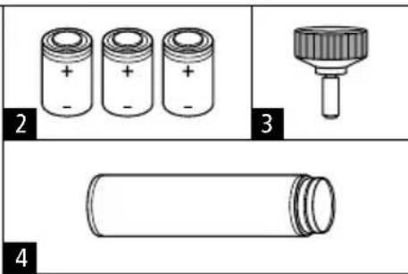
text_image
2 + - + - + - 3 4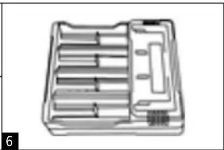
natural_image
Technical illustration of a mechanical tool holder with internal compartments (no text or symbols)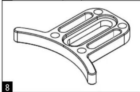
natural_image
Technical line drawing of a mechanical bracket component (no text or symbols)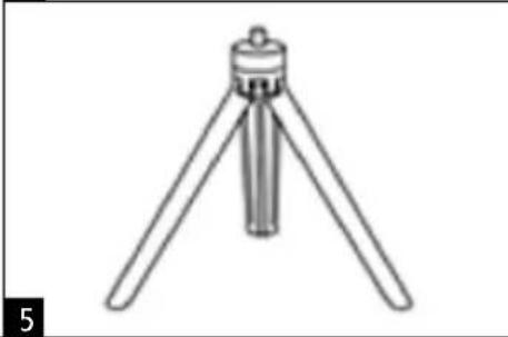
natural_image
Line drawing of a tripod-mounted scientific instrument with three legs and a central knob (no text or symbols)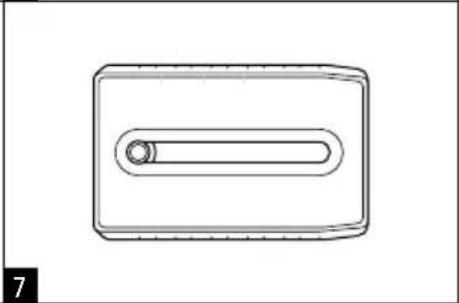
natural_image
Simple line drawing of a rectangular object with a central oval and a circular hole, no text or symbols present.natural_image
Pure diagram of four U-shaped pipe fittings with connectors, no text or symbols present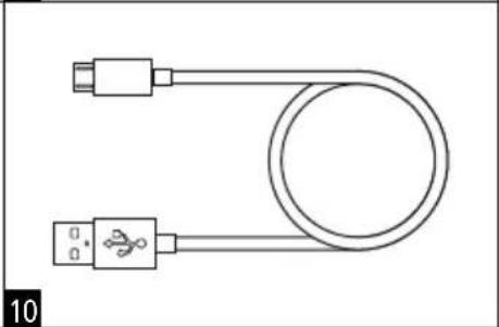
natural_image
Simple line drawing of a U-shaped cable with two USB connectors (no text or symbols)Optionales Zubehör
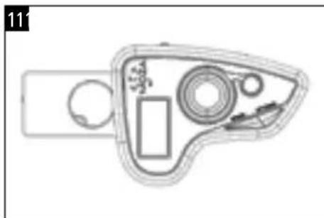
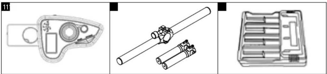
11 Rollei GO! DSLM Controller (Fernbedienung)
12 Rollei GO! DSLM Dual Handle (Doppelgriff)
13 Rollei GO! DSLM Charger (Ladegerät)
natural_image
Top-down schematic of a device casing with internal components (no text or labels)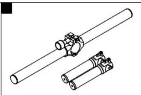
natural_image
Technical line drawing of two cylindrical mechanical components with no visible text or symbols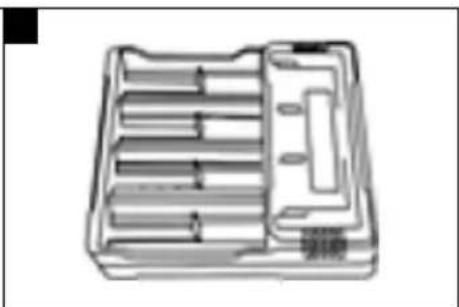
natural_image
Technical line drawing of a mechanical tool holder or tray with multiple parallel slots and a handle (no text or symbols)natural_image
Technical illustration of battery components including a cylindrical stack, two stacked cylinders, and a tray case (no text or symbols)Kamera montieren
flowchart
graph TD
    A["Initial Mount"] --> B["Assembly Step 1"]
    B --> C["Assembly Step 2"]
    C --> D["Final Assembly"]
text_image
Technical diagram of a robotic arm with labeled parts, showing mechanical components and orange arrows indicating motion or flow.1
text_image
Technical diagram of a DSLR camera with labeled parts including lens, frame, and adjustment lever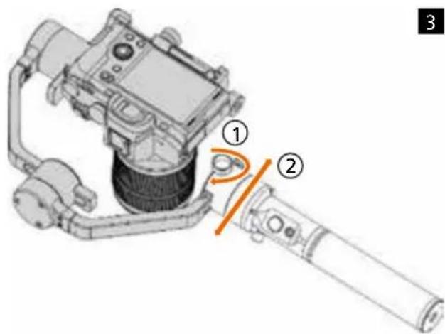
text_image
Technical diagram of a mechanical device with numbered components and an orange arrow indicating a joint or adjustment.natural_image
Technical line drawing of a robotic arm with labeled component (no text or symbols present)Technische Daten
Rollei GO! DSLM
1 Gimbal
2 Rechargeable batteries
3 Screw for lens support
4 Grip
5 Tripod
6 Charger
7 Quick-release plate & Arca Swiss adapter
8 Lens support
9 3x camera control cable (Panasonic, Sony, Canon)
10 USB cable (firmware update)
Optional accessories
11 Rollei GO! DSLM Controller
12 Rollei GO! DSLM Dual Handle
13 Rollei GO! DSLM Charger
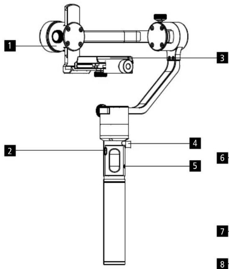
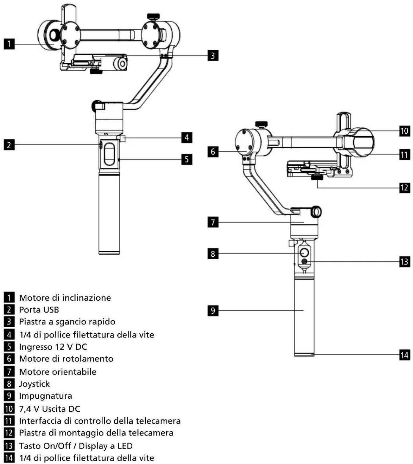
Rollei GO! DSLM Overview
text_image
1 2 3 4 5 6 7 8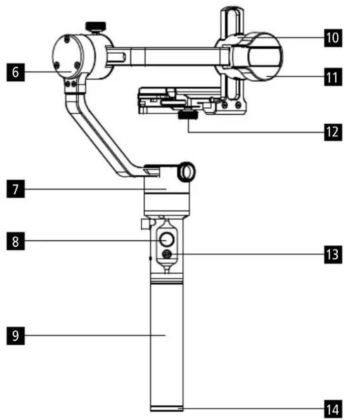
text_image
Technical diagram of a mechanical device with numbered components for identification1 Tilt Motor
2 USB Port
3 Quick-release plate
4 1/4 inch Screw Thread
5 12 V DC Input
6 Roll Motor
7 Pan Motor
8 Joystick
9 Grip
10 7.4 V DC Output
11 Camera Control Port
12 Camera Mounting Plate
13 On/Off button / LED Indicator
14 1/4 inch Screw Thread
Getting Started
Battery and charging
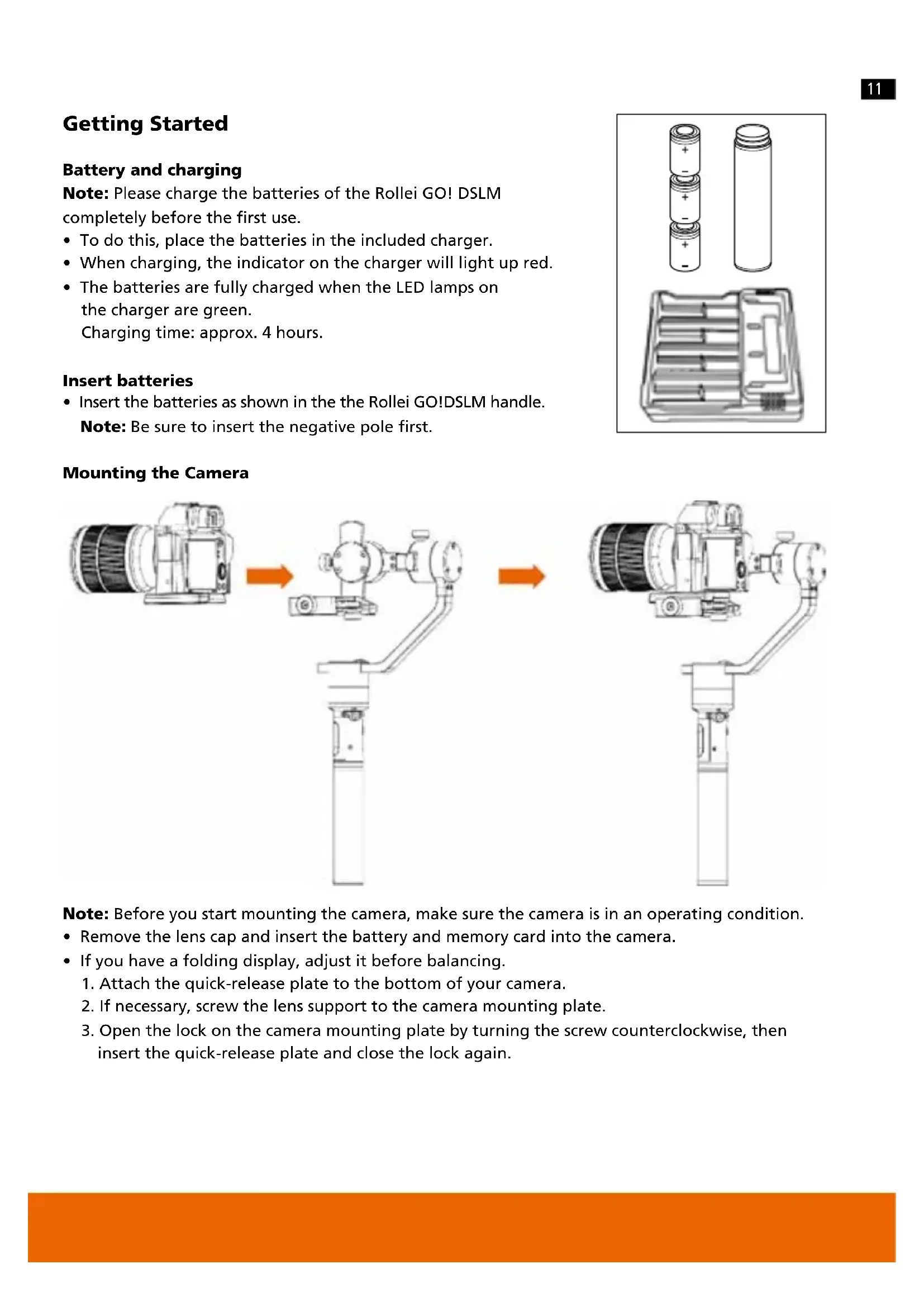
Note: Please charge the batteries of the Rollei GO! DSLM completely before the first use.
- To do this, place the batteries in the included charger.
- When charging, the indicator on the charger will light up red.
- The batteries are fully charged when the LED lamps on the charger are green.
Charging time: approx. 4 hours.
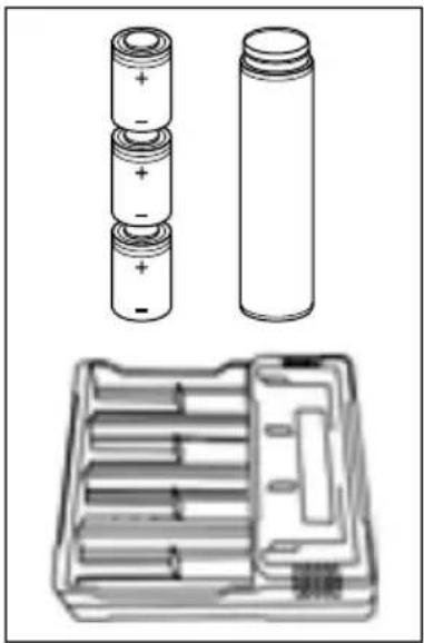
Insert batteries
- Insert the batteries as shown in the the Rollei GO!DSLM handle.
Note: Be sure to insert the negative pole first.
natural_image
Technical line drawing of battery components including a cylindrical stack, one open with internal compartments, and a separate labeled case (no text or symbols present)Mounting the Camera
flowchart
graph TD
    A["Sensor Input"] --> B["Actuator"]
    B --> C["Output"]
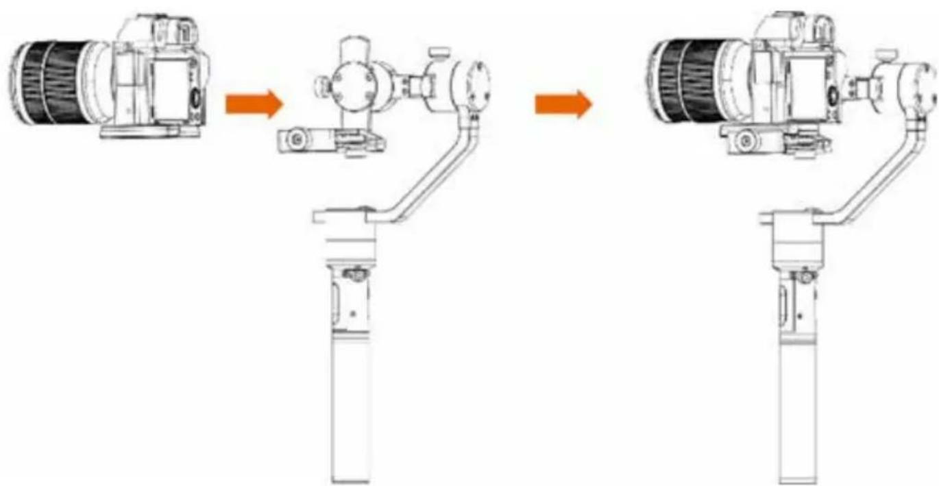
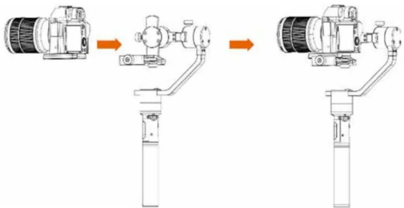
Note: Before you start mounting the camera, make sure the camera is in an operating condition.
- Remove the lens cap and insert the battery and memory card into the camera.
- If you have a folding display, adjust it before balancing.
- Attach the quick-release plate to the bottom of your camera.
- If necessary, screw the lens support to the camera mounting plate.
- Open the lock on the camera mounting plate by turning the screw counterclockwise, then insert the quick-release plate and close the lock again.
Getting Started
Balancing
Please see our video insturctions for calibration: www.rollei.com/RolleiGODSLM
- Slide the camera forward and backward on the mounting plate. When an approximate balance is reached, close the lock-knob.
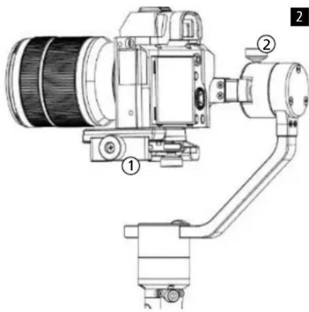
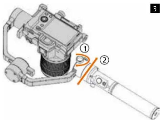
1. Balancing the Tilt Axis
a) Rotate the tilt axis so that the lens is pointing up.
Hold the tilt motor to ensure that the roll axis remains horizontal when balancing, and check that the camera is top- or bottom-heavy.
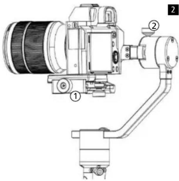
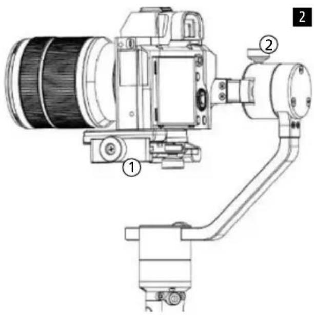
b) Loosen the screw ① on the tilt motor and adjust the balance ② until the camera does not tilt up or down.
c) Tighten the screw.
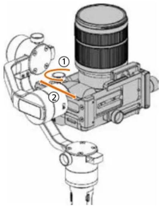
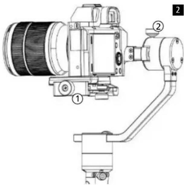
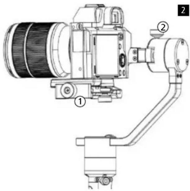
2. Balancing the Roll Axis
a) Adjust the tilt axis as shown in the illustration.
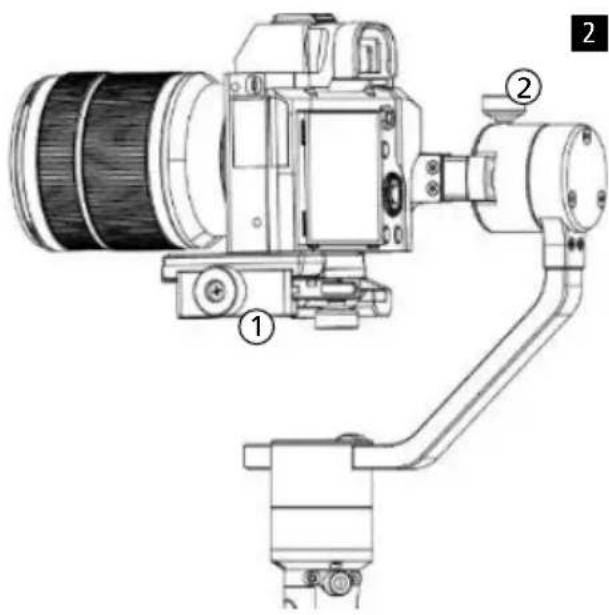
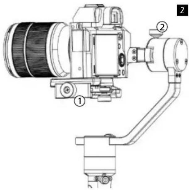
b) Loosen the screw on the camera mounting plate ① and slide the camera as close to the tilt motor as possible.
c) Loosen the roll axis screw ② and adjust the camera weight.
The camera is correctly balanced when the roll motor is parallel to the ground.
d) Tighten the screw.
3. Balancing the Pan Axis
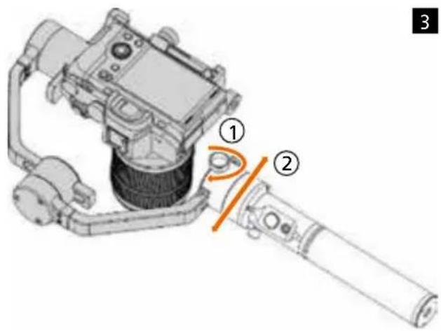
a) Hold the gimbal hoizuntal to the floor as illustrated.
b) Loosen the screw① on the pan motor and balance the camera weight②.
The camera is correctly balanced when the pan motor is still in position.
c) Tighten the screw.
text_image
Technical diagram of a robotic arm with labeled parts, showing mechanical components and motion indicators.1
text_image
Technical diagram of a DSLR camera with labeled parts including lens, frame, and adjustment lever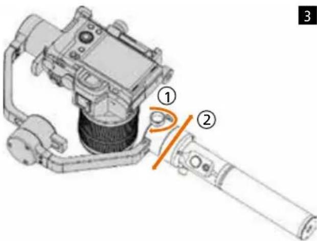
text_image
Technical diagram of a mechanical device with numbered components and an orange arrow indicating a rotation or adjustment.Controls and operation
Gimbal Motors
- Pan (Yaw) Follow: The Pan axis follows the movement. The tilt and roll axes are locked.
- Tilt – Pan (Yaw) Ffollow: The Tilt and Pan axis follows the movement. The roll axis is locked.
- All Lock Mode: All three axis are locked.
- All Follow Mode: All three axis follow the movement
Joystick
- Press once: Pan (Yaw) Follow Mode
- Fast double-click: Tilt – Pan (Yaw) Follow Mode
- Fast triple click: All Lock Mode
- Fast four times click: All Follow Mode
- When the gimbal is turned on: Press and hold the joystick, then briefly press the On/Off button to turn off the motors. Press the joystick again briefly to restart the motors.
- When the gimbal is turned on: Hold down the joystick and then press the On/Off button twice briefly: Auto Tuning.
Note: Here the gimbal calibrates the motors based on the payload and adjusts the motor parameters.
- When the gimbal is turned on: Hold down the joystick, then briefly press the On/Off button three times: Inception Mode.
Note: Then move the joystick left or right to rotate the camera.
Power button
- Long press: Switch on and off the Rollei GO! DSLM.
- Press once: Start/Stop recording.*
- Fast double-click: Take a Photo.
- Fast triple click: Re-Center the gimbal.
- Fast four times click: Activates the roll motor control.
Dual Handle Setup
- Mount the two side handles and secure them with the screw ①.
- Loosen the locking screw in the middle of the holder, then mount the double handle in the desired position ②.
- Tighten the screw.

text_image
① ① *Only in conjunction with the appropriate camera control cable.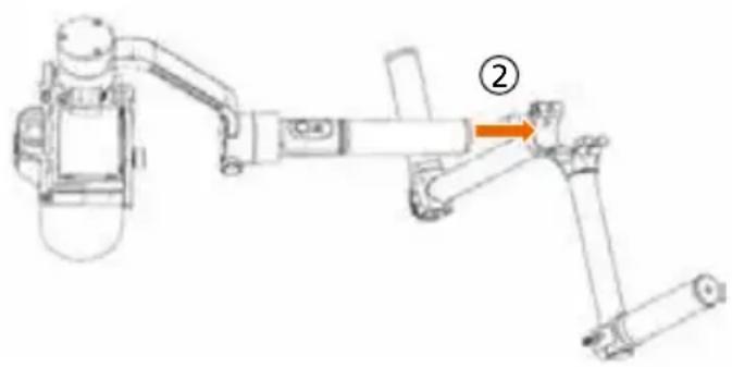
natural_image
Mechanical robotic arm diagram showing articulated joints and a highlighted joint (no text or symbols)Technical data
Rollei GO! DSLM
| Weight 896 g (without battery) |
| Dimensions 378 x 175 x 193 mm |
| Maximum payload 1800 g |
| Rotation Range 360° |
| Roll Rotation Range 360° |
| Yaw Speed Range 360° |
| Operating Voltage 9.8 – 12.6 V |
| Battery Life Up to 12 hours |
| Bluetooth ^®1 Bluetooth 4.0 |
| USB Input Micro USB 2.0 |
| DC Input 12.0 V |
| DC Output 7.4 V |
Battery
| Li-Ion ICR 26350 | 3.7 V | 2000 mAh | 7.4 Wh | == |
Charger
| Input Voltage 5.0 V DC | |
| Output Voltage | 4.2 V DC |
| Output Current | 500 mA X 4 |
| Charging Time | 4 hours |
Design and technical data are subject to change without notice.
1) The Bluetooth® word mark and logos are registered trademarks of Bluetooth SIG, Inc. and the use of these marks by Rollei is under license. Other trademarks and trade names are the property of their respective owners.
Disposal

Dispose of packaging: For disposal, separate packaging into different types. Cardboard and board must be disposed of as paper and foil must be recycled.

Disposal of Waste Electrical and Electronic Equipment and/or Battery by users in private households in the European Union. This symbol on the product or on the packaging indicates that this cannot be disposed of as a household waste. You must dispose of your waste equipment and/or battery by handling it over to the applicable take-back scheme for the recycling of electrical and electronic equipment and/or battery. For more information about recycling of this equipment and/or battery, please contact your city office, the shop where you purchased the equipment or your household waste disposal service. The recycling of materials will help to conserve natural resources and ensure that it is recycled in a manner that protects human health and environment.
Battery warning
- Never dismantle, crush, or pierce the battery, or allow the battery to short-circuit.
Do not expose battery being placed in high temperature environment, if battery leaks or bulges, stop continue to use. - Keep the battery out of reach of children.
- Batteries may explode if exposed to naked fire. Never dispose of batteries in a fire.
- Disposed of used batteries observing local regulations.
- Before disposing the device, please remove the battery.
Conformity
The Rollei GmbH & Co. KG herewith declare, that the Rollei GO! DSLM complies with the directive 2014/53/EU:
2011/65/EC RoHs Directive
2014/53/EU RED-Directive
CE
The complete text of the EU Declaration of Conformity can be downloaded at the following Internet address: www.rollei.com/EGK/rolleigodslm.
natural_image
Technical line drawing of a robotic arm with articulated joints and mounting brackets (no text or symbols)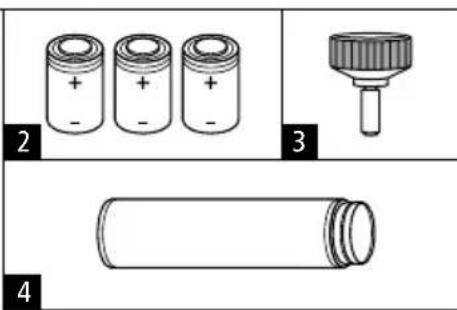
text_image
Diagram showing four components of batteries: two cylindrical cells, one labeled with a handle, and a cylindrical battery.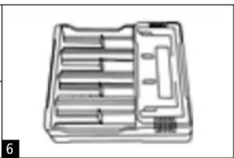
natural_image
Technical line drawing of a mechanical tool holder or tray with internal compartments (no text or symbols)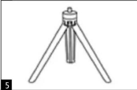
natural_image
Line drawing of a tripod-mounted scientific instrument with a central knob (no text or symbols)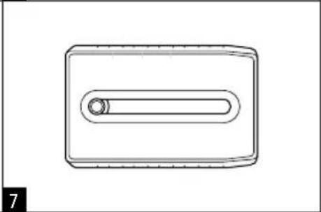
natural_image
Simple line drawing of a rectangular object with a central oval and a small circular hole, no text or symbols present.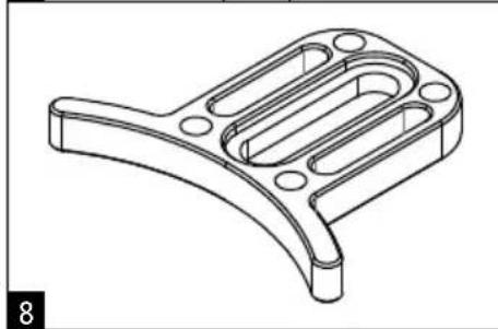
natural_image
Technical line drawing of a mechanical bracket component (no text or symbols)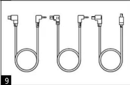
natural_image
Pure diagram of four U-shaped pipe fittings with connectors, no text or symbols present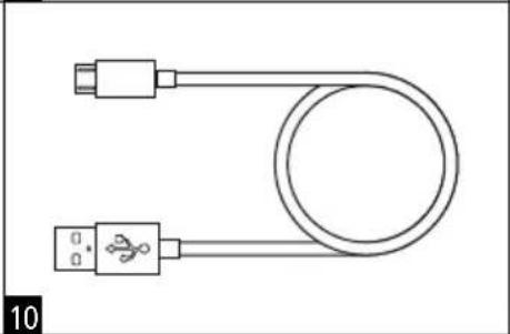
natural_image
Simple line drawing of a U-shaped cable with two connectors (no text or symbols)natural_image
Top-down schematic of a device layout with no visible text or symbols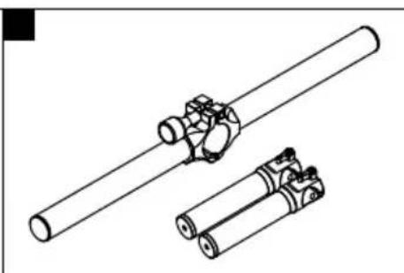
natural_image
Technical line drawing of two cylindrical mechanical components with no visible text or symbols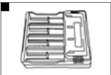
natural_image
Technical line drawing of a mechanical tool holder or tray with multiple parallel slots and a handle (no text or symbols)natural_image
Technical illustration of battery components including a cylindrical stack, two stacked cylinders, and a tray case (no text or symbols)flowchart
graph TD
    A["Initial Mount"] --> B["Assembly Step 1"]
    B --> C["Assembly Step 2"]
    C --> D["Final Assembly"]
text_image
Technical diagram of a robotic arm with labeled parts, showing mechanical components and orange arrows indicating motion or flow.1
text_image
Technical diagram of a DSLR camera with labeled parts including lens, frame, and adjustment lever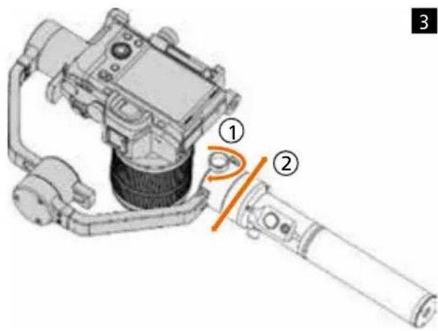
text_image
Technical diagram of a mechanical device with numbered components and labeled partsnatural_image
Technical line drawing of a robotic arm with labeled joint (②), no text or symbols presentnatural_image
Technical line drawings of battery components including a cylindrical stack, two stacked cylinders, and a tray case (no text or symbols)text_image
Technical diagram of a robotic arm with labeled parts, showing mechanical components and motion indicators.1
text_image
Technical diagram of a DSLR camera with labeled parts including lens, frame, and adjustment lever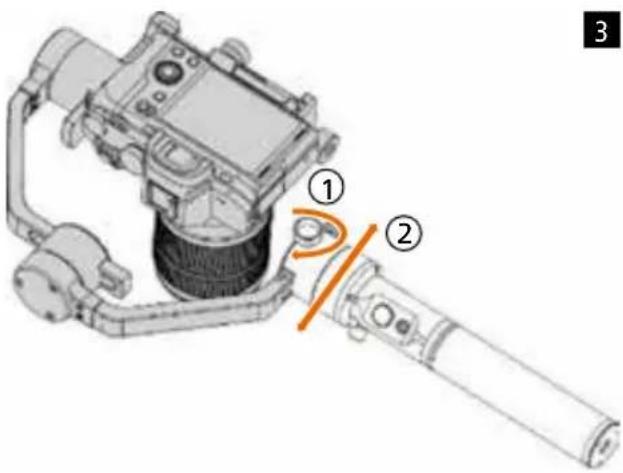
text_image
Technical diagram of a mechanical device with numbered components and an orange arrow indicating a specific section.natural_image
Technical line drawing of a robotic arm with labeled component (no text or symbols present)Datos técnicos
Rollei GO! DSLM
natural_image
Technical line drawing of a robotic arm with articulated joints and mounting brackets (no text or symbols)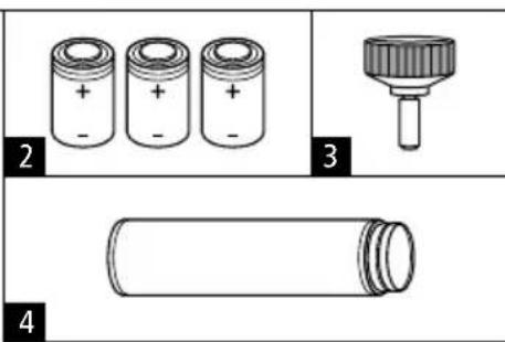
text_image
2 + - + - + - 3 4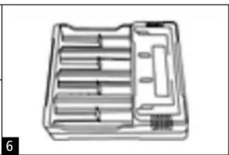
natural_image
Technical line drawing of a mechanical tool holder or tray with internal compartments (no text or symbols)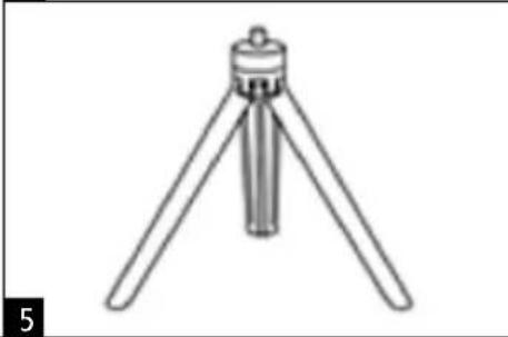
natural_image
Line drawing of a tripod-mounted scientific instrument with a central knob (no text or symbols)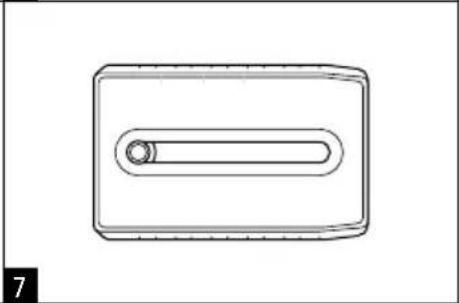
natural_image
Simple line drawing of a rectangular device with a central oval and a circular end (no text or symbols)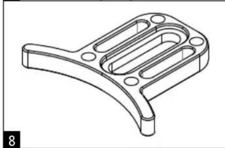
natural_image
Technical line drawing of a mechanical bracket component (no text or symbols)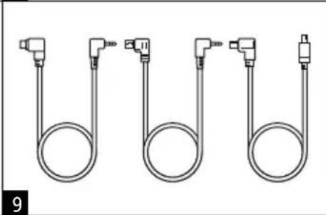
natural_image
Pure diagram of four U-shaped pipe fittings with connectors, no text or symbols present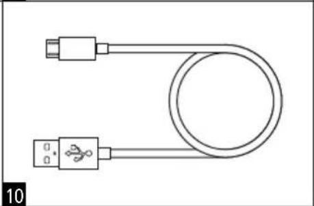
natural_image
Simple line drawing of a U-shaped cable with two connectors (no text or symbols)natural_image
Top-down schematic of a device layout with no visible text or symbols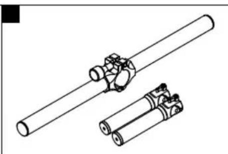
natural_image
Technical line drawing of two cylindrical mechanical components with no visible text or symbols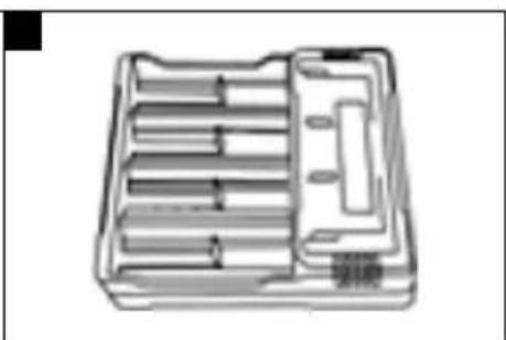
natural_image
Technical line drawing of a mechanical tool holder or tray with multiple parallel slots and a handle (no text or symbols)Panoramica del Rollei GO! DSLM
natural_image
Technical illustration of battery components including a cylindrical stack, two stacked cylinders, and a tray case (no text or symbols)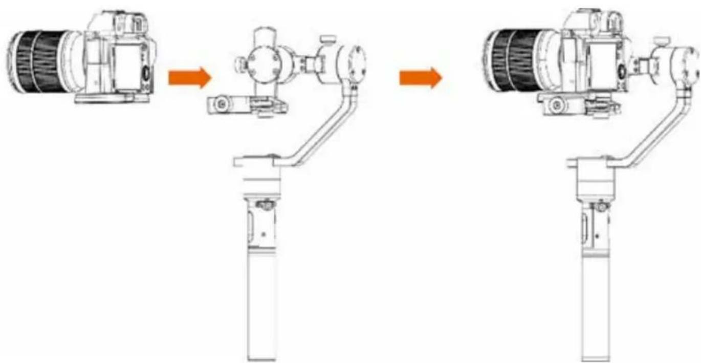
flowchart
graph LR
    A["Sensor"] --> B["Internal Control Valve"]
    B --> C["Motor with Base"]
    C --> D["Branching System"]
    D --> E["Final Assembly"]
text_image
Technical diagram of a robotic arm with labeled parts, showing mechanical components and orange motion indicators.1
text_image
Technical diagram of a DSLR camera with labeled parts including lens, frame, and adjustment lever2
text_image
Technical diagram of a mechanical device with numbered components and an orange arc indicating a joint or connection point.3
natural_image
Technical line drawing of a robotic arm with labeled component (no text or symbols present)Dati tecnici
Rollei GO! DSLM
natural_image
Technical line drawing of battery components including a cylindrical stack, one open with internal compartments, and a separate labeled case (no text or symbols present)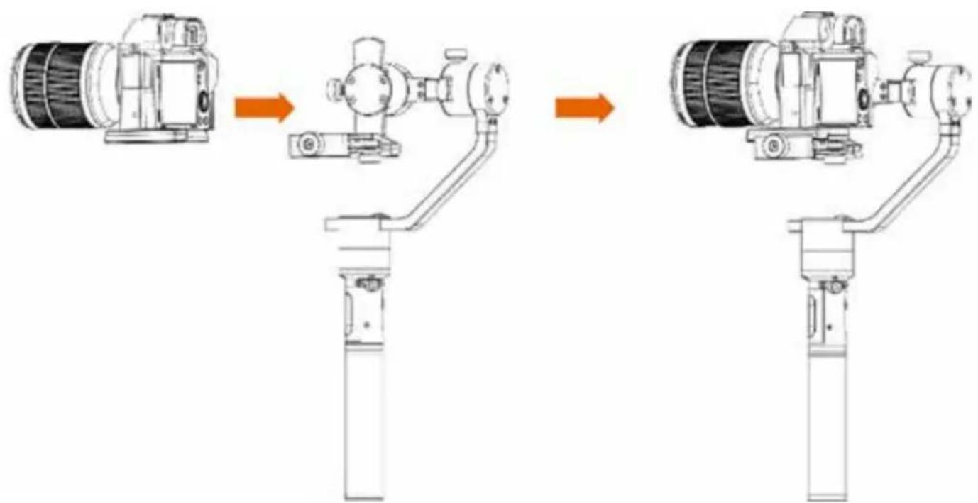
flowchart
graph TD
    A["Initial Robot"] --> B["Assembly Step 1"]
    B --> C["Assembly Step 2"]
    C --> D["Final Assembly"]
Montagem da câmera
text_image
Technical diagram of a mechanical device with labeled parts and orange arrows indicating motion or flow direction.1
text_image
Technical diagram of a DSLR camera with labeled parts including lens, frame, and adjustment lever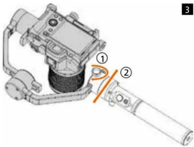
text_image
Technical diagram of a mechanical device with numbered components and an orange arrow indicating a specific section.natural_image
Mechanical robotic arm diagram showing articulated joints and a highlighted joint (no text or symbols)Dados técnicos
Rollei GO! DSLM
natural_image
Technical line drawing of a robotic arm with articulated joints and mounting brackets (no text or symbols)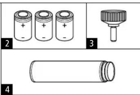
text_image
2 + - + - + - 3 4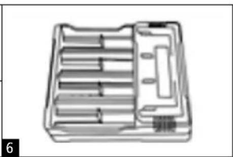
natural_image
Technical line drawing of a mechanical tool holder or tray with internal compartments (no text or symbols)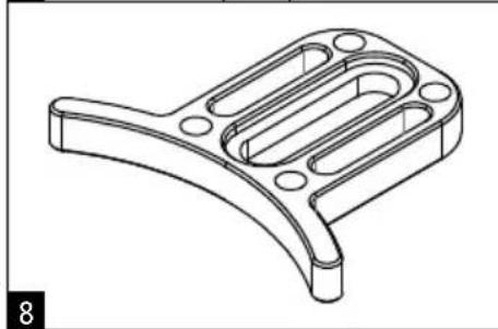
natural_image
Technical line drawing of a mechanical bracket component (no text or symbols)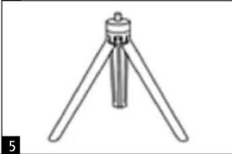
natural_image
Line drawing of a tripod-mounted scientific instrument with three legs and a central knob (no text or symbols)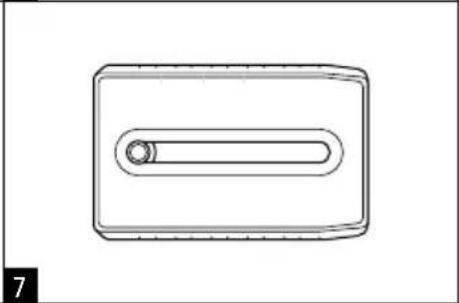
natural_image
Simple line drawing of a rectangular object with a central oval and a circular hole, no text or symbols present.natural_image
Pure diagram of four U-shaped pipe fittings with connectors, no text or symbols present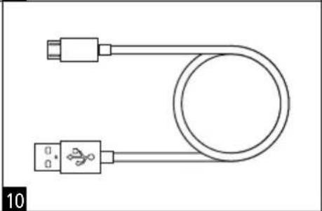
natural_image
Simple line drawing of a U-shaped cable with two USB connectors (no text or symbols)Optionele accessoires
11 Rollei GO! DSLM Controller (afstandsbediening)
12 Rollei GO! DSLM Dual Handle (dubbele handgreep)
13 Rollei GO! DSLM Charger (lader)
natural_image
Top-down schematic of a device layout with no visible text or symbols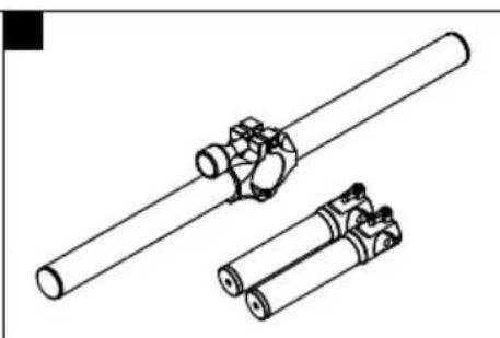
natural_image
Technical line drawing of two cylindrical mechanical components with no visible text or symbols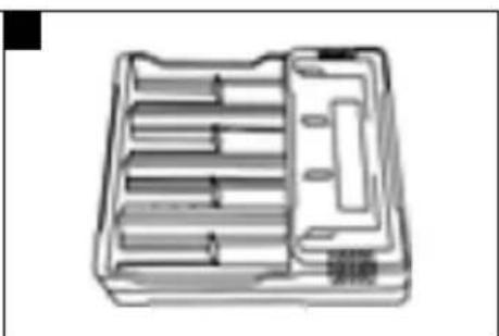
natural_image
Technical line drawing of a mechanical tool holder or tray with multiple parallel slots and a handle (no text or symbols)natural_image
Technical illustration of battery components including a cylindrical stack, two stacked cylinders, and a tray case (no text or symbols)Montage van de camera

flowchart
graph TD
    A["Sensor Input"] --> B["Actuator"]
    B --> C["Output"]
text_image
Technical diagram of a robotic arm with labeled parts and orange arrows indicating motion or assembly.1
text_image
Technical diagram of a DSLR camera with labeled parts including lens, frame, and adjustment lever2
text_image
Technical diagram of a mechanical device with numbered components and highlighted parts3
Bedienings- en bedieningselementen
Gimbal Motoren
text_image
Technical diagram of a robotic arm with labeled component ② and directional arrowTechnische gegevens
Rollei GO! DSLM
www.rollei.com/social