SmartView 4K G3 - Monitor Blackmagic Design - Free user manual and instructions
Find the device manual for free SmartView 4K G3 Blackmagic Design in PDF.
| Product type | 4K Broadcast Monitor |
| Screen size | 15.6 inches (diagonal) |
| Native resolution | 3840 x 2160 (Ultra HD 4K) |
| Supported video formats | SD, HD, 2K, Ultra HD up to 2160p60 |
| Video inputs | 2 x 12G-SDI (BNC) |
| Video output | 1 x 12G-SDI loop (BNC) |
| Network connectivity | 1 x 10G Ethernet (RJ45) for IP ST 2110 |
| SFP module | 1 SFP port for fiber optic (Ethernet or SDI) |
| USB port | USB-C for configuration and firmware update |
| Tally port | D-sub 9-pin for contact closure signals |
| Power supply | AC 100-240V or DC 12V (24W) |
| Mounting | 6U rack (19 inches), VESA compatible |
| Front panel functions | Buttons: Input, Disp, H/V Delay, Blue Only, Zoom, Peak, 3D LUT 1/2, H Mark, V Mark, up/down arrows, power |
| Configuration software | Blackmagic SmartView Setup (Windows/Mac) |
| LUT support | 3D LUT in .cube format (2 slots) |
| Monitoring functions | Focus peaking (2 levels), zoom, blue channel display, image markers |
| IP codec | Blackmagic IP10 for Ultra HD 2160p50/60 over 10G Ethernet |
| Operating temperature | 40°C max |
| Maximum altitude | 2000 m |
| Warranty | 12 months |
| Maintenance | Clean with a soft dry cloth. Do not use liquids. |
Frequently Asked Questions - SmartView 4K G3 Blackmagic Design
User questions about SmartView 4K G3 Blackmagic Design
0 question about this device. Answer the ones you know or ask your own.
Ask a new question about this device
Download the instructions for your Monitor in PDF format for free! Find your manual SmartView 4K G3 - Blackmagic Design and take your electronic device back in hand. On this page are published all the documents necessary for the use of your device. SmartView 4K G3 by Blackmagic Design.
USER MANUAL SmartView 4K G3 Blackmagic Design
SmartView SmartScope

Languages
To go directly to your preferred language, simply click on the hyperlinks listed in the contents below.
English 3
日本語 46
Francais 90
Deutsch 134
Espanol 178
中文 222
HAnKoHa...266
Pycckn 310
Italiano 354
Portugués 398
Türkce 442

Welcome!
We hope you share our dream for the television industry to become a truly creative industry by allowing anyone to have access to the highest quality video.
Video monitoring is needed everywhere in a facility. SmartView 4K G3 has a native 4K 15.6" LCD so you can monitor Ultra HD video in full resolution, plus a sleek 6RU housing with a control panel that lets you quickly change settings. SmartScope Duo 4K features two independent 8" LCDs with waveform scope functionality, allowing you to monitor your video levels on the fly. All SmartView monitors support SD, HD and 2K video via 3G-SDI. SmartScope Duo 4K and SmartView 4K G3 also support Ultra HD via 6G-SDI and 12G-SDI respectively and SmartView 4K G3 also supports SMPTE 2110 IP and Blackmagic IP10.
Video monitoring is designed to work straight out of the box and our Blackmagic SmartView Setup software provides the user with an easy and intuitive configuration tool.
This instruction manual should contain all the information you'll need on installing your SmartView or SmartScope, although it's always a good idea to ask a technical assistant for help if you are not sure what IP addresses are, or if you don't know much about computer networks. SmartView and SmartScope are easy to install, however, there are a few slightly technical preferences you may need to set after you install it.
We think it should take you approximately 5 minutes to complete Installation. Please check our website at www.blackmagicdesign.com and click the support page to download the latest updates to this manual and SmartView software. Lastly, please register your unit when downloading software updates so we can keep you updated when new software is released. We are constantly working on new features and improvements, so we would love to hear from you!

Grant Petty
CEO Blackmagic Design
Contents
Getting Started 5 Vectorscope Display 25
Introducing SmartView and SmartScope 5 Parade Display 26
Plugging in Video Sources 6 Histogram Display 28
Plugging in your Computer 7 Audio Metering Display 29
Using Blackmagic SmartView Setup 8 Network Settings 30
Installling Blackmagic SmartView Setup 8 Connecting to a Network 31
Updating the Software 9 Direct Ethernet 31
UsingSmartView4KG3 10 Ethernet Network Switch 32
Control Panel Buttons 11 Using Tally 33
Blackmagic IP10 Video Codec 13 Tally Port Pin Connections 33
Changing Settings Using Optimizing the Viewing Angle 34
SmartView Setup 14 Developer Information 36
Setup Tab 14 Blackmagic 2K Format - Overview 36
2110 Tab 17 Blackmagic 2K Format - Vertical
LUTS Tab 19 Timing Reference 37
SmartView and SmartScope Duo 4K 20 Blackmagic 2K Format - Data
Adjusting Monitor Settings 20
Enable Tally Override 22 Protocol v1.4 38
Using SmartScope Duo 4K 22 Help 42
What is Blackmagic SmartScope? 22 Regulatory Notices 43
Video Monitoring Display 23 Safety Information 44
Waveform Display 24 Warranty 45
Getting Started
Introducing SmartView and SmartScope
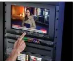
SmartView monitors are perfect for any facility which requires rack-based monitoring. To simply get up and running, the only thing you need to do is plug in power and connect an SDI source!
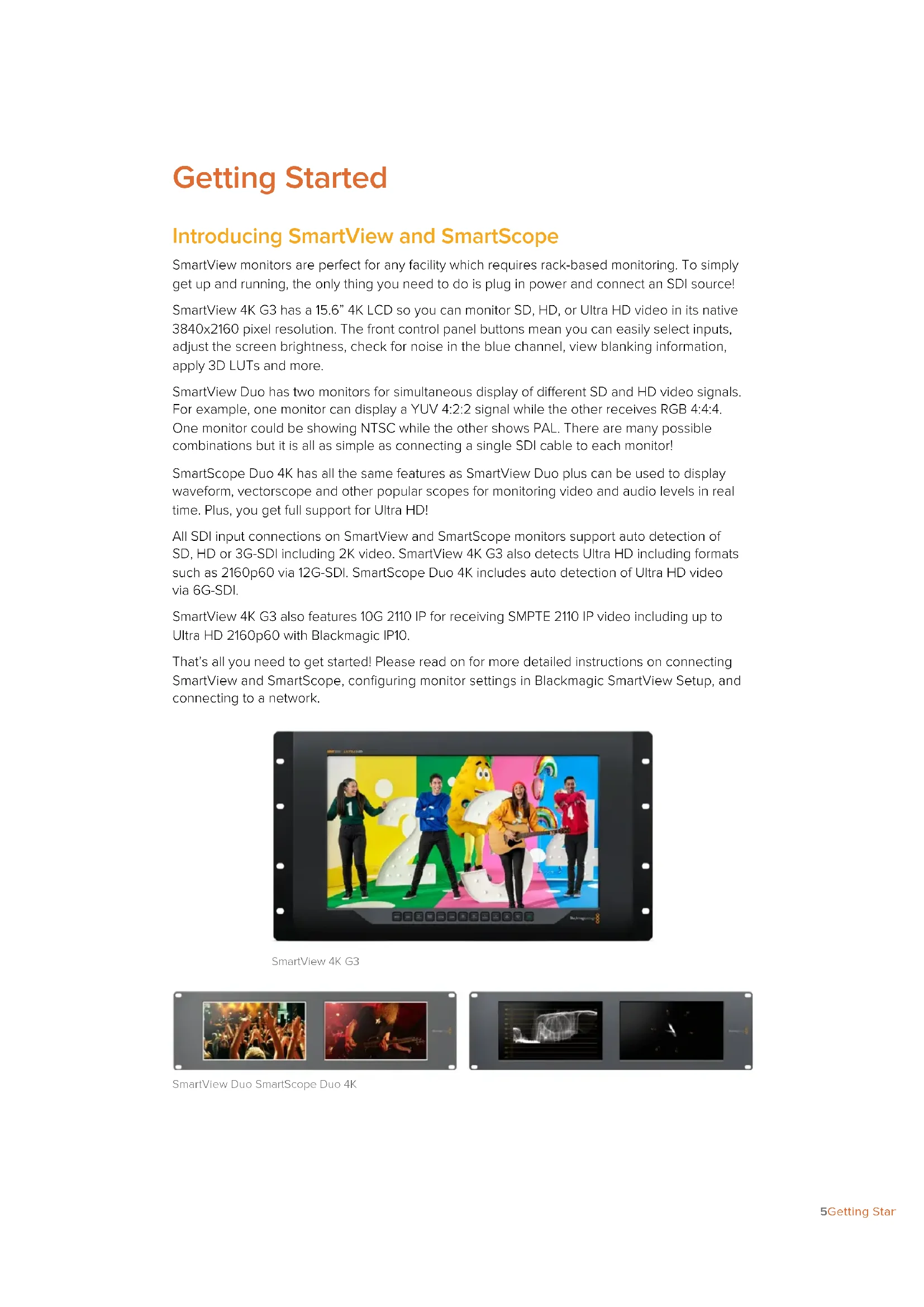
SmartView 4K G3 has a 15.6" 4K LCD so you can monitor SD, HD, or Ultra HD video in its native 3840x2160 pixel resolution. The front control panel buttons mean you can easily select inputs, adjust the screen brightness, check for noise in the blue channel, view blanking information, apply 3D LUTs and more.
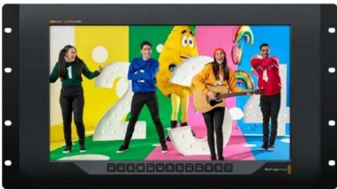
SmartView Duo has two monitors for simultaneous display of different SD and HD video signals. For example, one monitor can display a YUV 4:2:2 signal while the other receives RGB 4:4:4. One monitor could be showing NTSC while the other shows PAL. There are many possible combinations but it is all as simple as connecting a single SDI cable to each monitor!
SmartScope Duo 4K has all the same features as SmartView Duo plus can be used to display waveform, vectorscope and other popular scopes for monitoring video and audio levels in real time. Plus, you get full support for Ultra HD!
All SDI input connections on SmartView and SmartScope monitors support auto detection of SD, HD or 3G-SDI including 2K video. SmartView 4K G3 also detects Ultra HD including formats such as 2160p60 via 12G-SDI. SmartScope Duo 4K includes auto detection of Ultra HD video via 6G-SDI.
SmartView 4K G3 also features 10G 2110 IP for receiving SMPTE 2110 IP video including up to Ultra HD 2160p60 with Blackmagic IP10.
That's all you need to get started! Please read on for more detailed instructions on connecting SmartView and SmartScope, configuring monitor settings in Blackmagic SmartView Setup, and connecting to a network.
SmartView 4K G3
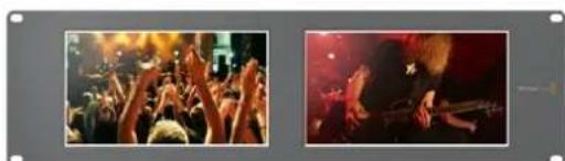
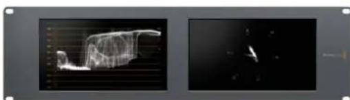
SmartView Duo SmartScope Duo 4K
Plugging in Video Sources
SmartView and SmartScope monitors feature regular BNC connectors to connect to SDI equipment including switchers, cameras, capture cards, decks and disk recorders.
Getting a Picture
Displaying your video is easy! Simply power the unit and connect your video source to an SDI input. Once powered and connected, your video should be immediately visible. SD, HD and 2K signals are automatically detected by the SDI input and loop through output connections. SmartView 4K G3 and SmartScope Duo 4K also detects Ultra HD.
When no video is received by the unit, the backlight turns off, saving power until the next valid signal is received.
To view ST 2110 IP video on SmartView 4K G3, connect using the 10G Ethernet port or using an optional optical fiber SFP module.

Daisy Chaining Monitors
Each SmartView and SmartScope monitor has its own independent SDI input as well as a loop through output so you can chain multiple monitors together to display the same input signal:
1 Power on unit 1. Connect a video source to an SDI input. The video should immediately be visible.
2 Power on unit 2. Connect an SDI cable from a loop output of unit 1 to an SDI input on unit 2.
There is no limit to the amount of units you can chain.
If you are waveform monitoring using SmartScope Duo 4K, you'll probably want to loop the Monitor 1 output to Monitor 2 so both displays use the same input signal.
Now you have video displayed, you can adjust monitor settings, or select scopes on SmartScope Duo 4K using the Blackmagic SmartView Setup software, which you can also use to load 3D LUTs on Blackmagic SmartView 4K G3.
SmartView Duo SmartScope Duo 4K
Plugging in your Computer
Configure SmartView or SmartScope monitor settings by connecting to your computer via USB and installing Blackmagic SmartView Setup.
The USB connection can also be used for applying internal software updates downloaded from the Blackmagic Design website. Software updates can provide new features, compatibility with new hardware and support for new formats. Blackmagic SmartView Setup runs on both Mac and Windows computers.
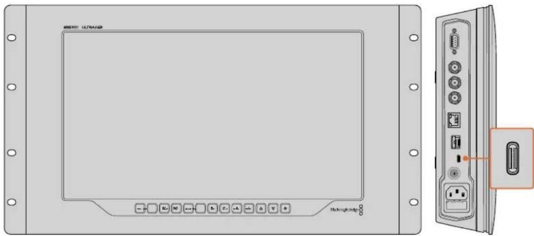
The USB-C port is located on SmartView 4K G3's side panel
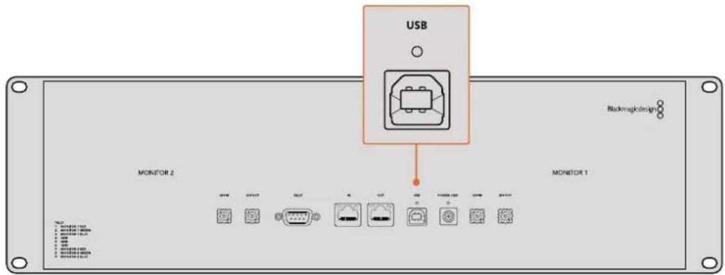
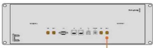
On SmartView Duo, the USB port is located on the rear panel
Using Blackmagic SmartView Setup
Installing Blackmagic SmartView Setup
Blackmagic SmartView Setup runs on the latest versions of Mac OS, plus 64-bit versions of Windows 10 and 11 with the latest service packs installed. Blackmagic SmartView Setup can be installed on multiple networked computers if desired.
The setup software installer can be downloaded at www.blackmagicdesign.com/support. This will ensure you have the latest version.
To install Blackmagic SmartView Setup:
1 From a web browser navigate to www.blackmagicdesign.com/support/family/video-and-audio-monitoring and download the latest Blackmagic SmartView utility.
2 When the file has finished downloading, double click 'install SmartView' icon to run the installer. Follow the prompts to the end and press 'install' to install the software.
3 Once the software is installed, navigate to 'Blackmagic SmartView' folder in your applications or programs folder and double click 'SmartView Setup'.


SmartView Manual

InstallSmartView 5.0

Uninstall SmartView
Blackmagickdesign

To install on a Mac computer, launch the SmartView.dmg file from your downloads folder, then double click on the Install SmartView icon
Updating the Software
Once Blackmagic SmartView Setup is installed and launched, click on the settings icon below the name of your monitor. You may be prompted to update the internal software of your SmartView or SmartScope. To do so:
1 Connect your SmartView or SmartScope to the computer via USB or Ethernet and launch Blackmagic SmartView Setup.
2 When prompted, simply click update. The update may take about 5 minutes to complete.
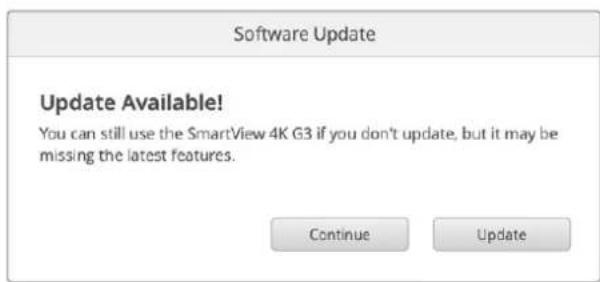
3 The message: "This SmartView has been updated" should appear upon completion of the update.
4 Click close.
If no internal software update is required, Blackmagic SmartView Setup will open the settings page for your monitor.
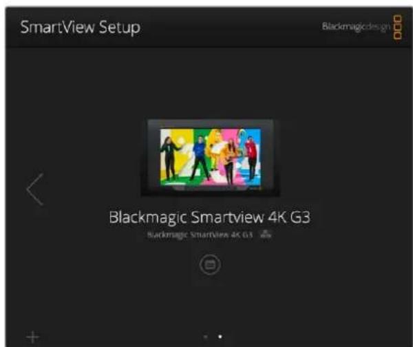
Blackmagic SmartView Setup automatically searches for any SmartView and SmartScope units connected locally via USB or over a network. Use the arrows on each side of the home page to navigate between monitors if you have more than one connected to you network. When updating your monitor's internal software make sure your monitor is connected via USB or Ethernet.
Using SmartView 4K G3
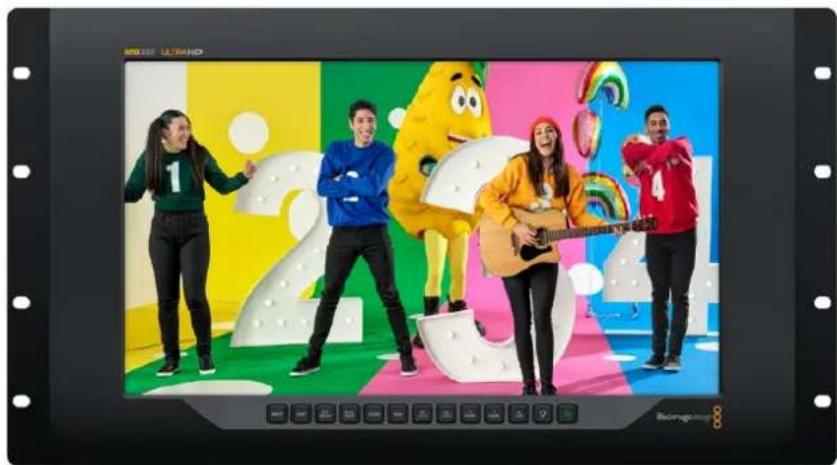
SmartView 4K G3 is a 6 rack unit Ultra HD 12G-SDI broadcast monitor for displaying SD, HD and native viewing of up to 2160p60 Ultra HD video. With a bright display and a wide viewing angle, SmartView 4K G3 provides a vibrant, crystal clear picture for accurate focus and color monitoring, and supports virtually every video format.
Designed for studio and outside broadcast environments, SmartView 4K G3 is incredibly easy to use. Featuring side mounted connectors and VESA support, you can fit the unit into tight spaces, or mounted on a wall or articulated arm. SmartView 4K G3 can be operated using the built in control panel, or remotely via Ethernet if you don't have access to the front panel.
Two multi rate 12G-SDI inputs let you select between two SDI sources, plus a 2110 IP 10G Ethernet connector for networking, remote control and ST 2110 IP video and SFP optical fiber connector that supports 2110 IP video and optical SDI. Other connectors include a tally input for live production, and a USB port for changing settings and internal software updates using Blackmagic SmartView Setup.
You can even load industry standard 3D LUTs with .cube extension or DaVinci Resolve generated LUTs using the Blackmagic SmartView Setup! With 3D LUTs you can connect your SmartView 4K G3 directly to your camera and view your clips as close to the final grade as possible. Two levels of focus peaking let you make sure your shots are in perfect focus, and with support for AC and DC power you have the option to plug SmartView 4K G3 into mains power, or an external battery for portability on set.
SmartView 4K G3 is the perfect monitoring solution for portable and studio broadcast production displaying video in SD, HD, and Ultra HD in its native 3840x2160 pixel resolution.
NOTE If connecting external power via the DC power input, ensure your external power output is capable of supplying 24 watts at 12 volts.
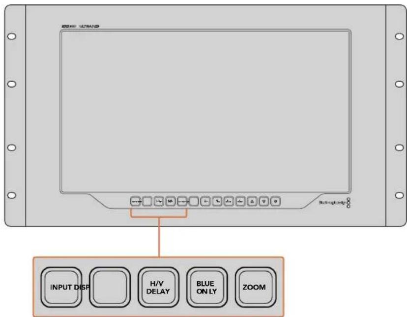
Control Panel Buttons
The control panel features a row of buttons so you can quickly adjust settings.
Input
Pressing this button cycles through the video signals connected to SmartView 4K G3's two 12G-SDI inputs, subscribed 2110 IP streams and optional optical fiber SFP module input. If there is no video connected to an input, SmartView 4K G3 will display black for that input. When switching between inputs, information about your connected input format will be momentarily displayed on the top left corner of your monitor.
Display
The 'disp' button is used to adjust the brightness setting on your SmartView 4K G3's LCD. Adjust brightness by pressing the up and down arrow buttons. Press the 'disp' button again to close the setting.
H/V Delay
Pressing the 'H/V delay' button lets you quickly confirm the presence of ancillary data embedded in your SDI video signal. For example, press the H/V delay button once to view the horizontal ancillary data. Press the H/V delay button again to view the vertical ancillary data, commonly used for data such as closed captions.
Blue Only
Any noise in a digital video signal is more predominant in the blue channel so the overall amount of noise can be monitored using the 'blue only' button. This displays only the blue channel represented as a black and white image. This black and white image can also be used for assistance when checking camera focus.
Zoom
A method of achieving crisp camera focus is to use the 'zoom' button. Press once to zoom into the image. Now you can see clearly if an object is in focus. Press zoom again to return to normal viewing size.
Peak
Camera focus can easily be checked by pressing the 'peak' button to enable focus peaking. This displays a bright green edge around the sharpest points in your image. There are two levels of peaking strengths which you can cycle through with subsequent pressing of the peak button. When the green edges are at their strongest, you can be sure your camera is in focus.
3D LUT 1 and 3D LUT 2
The LUT buttons let you view your image using custom 3D LUTs generated in DaVinci Resolve, or industry standard .cube LUTs. Press a LUT button once to enable the LUT. Press again to disable the LUT. Refer to the 'loading 3D LUTs using Blackmagic SmartView Setup' section for more information on using 3D LUTs with SmartView 4K G3.
H Mark and V Mark
You can view and edit frame markers using the 'H mark' and 'V mark' buttons. Frame markers help you compose shots or keep important information or graphics within the safe area of the screen. Different televisions display slightly more or less of the edges of a video signal, so it's handy to view a safe area. A safe area is the section of the screen that will always be visible no matter what television or monitor is being used to view it.
To view horizontal and vertical frame markers, press the H mark and V mark buttons respectively. To edit the markers, press each respective button again to highlight each guide. This allows you to edit the markers' positions using the up and down arrow buttons. Subsequent presses of each button will confirm your new positions. Another press turns the markers off.
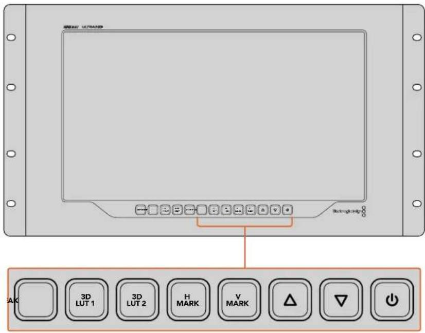
Up and Down Arrow Buttons
Use the up and down arrow buttons when editing a setting, for example adjusting the display brightness or editing frame marker positions.
Power
Press the power button once to turn your SmartView 4K G3 on. Press again to turn off.
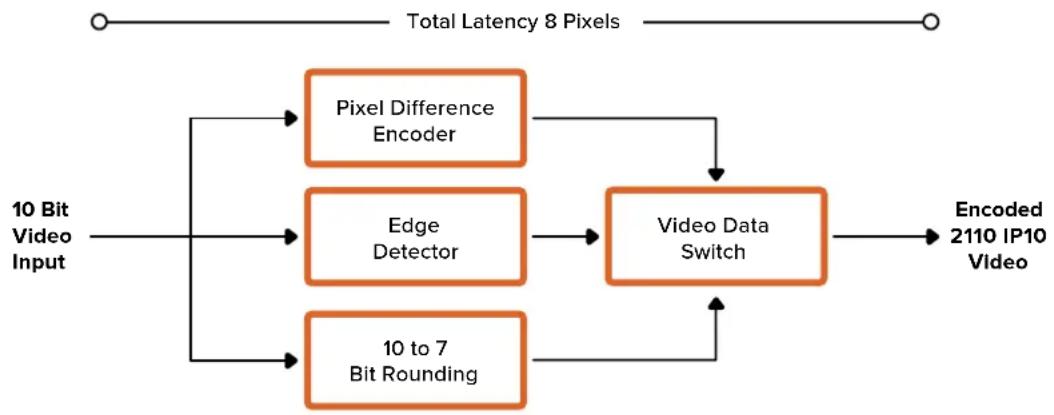
Blackmagic IP10 Video Codec
You can send uncompressed ST 2110 IP video over 10G Ethernet at frame rates up to 2160p50 Ultra HD, just like on an SDI video network. For the high frame rates, like 2160p59.94 and 2160p60, you'll need to lower the data rate enough to fit down a 10G Ethernet port. This is where Blackmagic IP10 comes in. It's a simple 'codec' that changes from pixels being an absolute quantizing level as used in normal uncompressed video to a difference number that shows the difference between pixels. On hard edges in the image, it can also reduce the bit depth of these pixels because it's not visible.
The goal is to fit a 12G-SDI signal into a 10G Ethernet port, so only a little bit of image data needs to be removed. The big advantage of using 10G Ethernet for high frame rate Ultra HD video is a dramatically lower cost because products can be simple and use less power. This makes IP mini converter type products possible and the cost of Ethernet switches is also much lower as low cost 10G Ethernet switches are very common. You can also use simple 10G Ethernet copper cables that are already installed in a lot of buildings and you even have the option to remove power converters over PoE.
For detailed information on Blackmagic IP10 including the developer documents and reference software, refer to the Blackmagic 2110 IP Converters products page on the website www.blackmagicdesign.com/products/blackmagic2110ipconverter#ip10codec
This information should provide enough detail for developers to incorporate Blackmagic IP10 into other products.
Changing Settings Using SmartView Setup
Adjust network settings and subscribe to ST 2110 IP video streams using Blackmagic SmartView Setup.
Setup Tab
Setup settings let you change the name of your SmartView, change network settings, displays the current version of your SmartView's internal software, SDI output and tally settings.
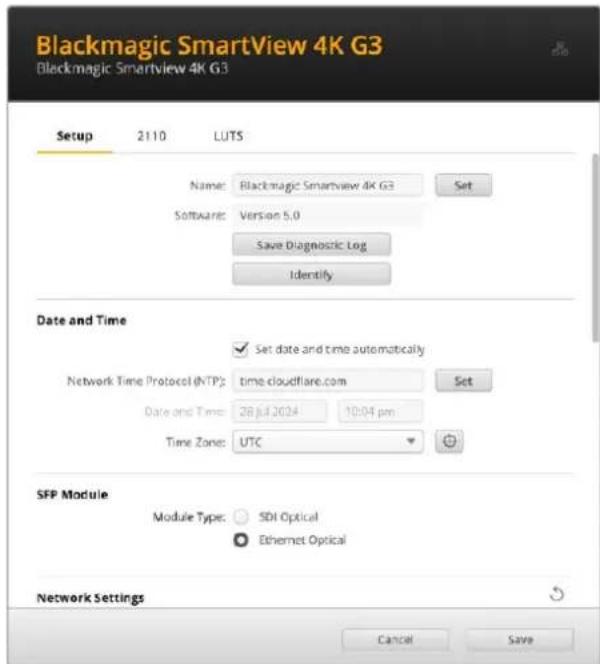
If you have more than one SmartView 4K G3 it can be helpful to rename them so they are easier to identify on your network. To change the name, enter the name and click 'set'. You can also locate the SmartView monitor by clicking the 'identify' button. When selected, the SmartView border will appear white for 15 seconds.
Date and Time
Set your date and time automatically by ticking the box. When setting the date and time automatically, your monitor will use the network time protocol server set in the NTP field. The default NTP server is time.cloudflare.com, but you can also manually enter an alternate NTP server and then click on 'set'.
If you are entering your date and time manually, use the fields to enter your date, time and time zone. Setting the date and time correctly ensures your recordings have the same time and date information as your network and also prevents conflicts that can occur with some network systems.
SFP Module
SmartView 4K G3 is 2110 IP is compatible with both Ethernet and SDI SFP modules. If you are using an SFP module, select between 'SDI optical' and 'Ethernet optical' to confirm the type of SFP in use.
Network Settings
Network Location
The network location is the name for your SmartView 4K G3 that will appear in the registry. This is based on the identification name at the top of the setup utility. It's worth noting that numeric prefixes will be ignored.
MAC Address
This field displays the MAC address of the SmartView 4K G3 monitor.

Protocol
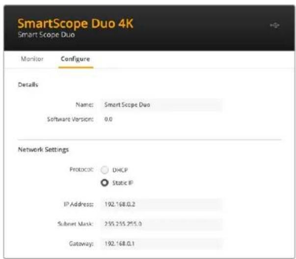
DHCP and static IP settings let you determine how your SmartView is connected to your network.
| DHCP SmartView 4K G3 monitors are set to DHCP by default. The dynamic host configuration protocol, or DHCP, is a service on network servers that automatically finds your SmartView monitor and assigns an IP address. DHCP is a great service that makes it easy to connect equipment via Ethernet and ensure their IP addresses do not conflict with each other. Most computers and network switchers support DHCP. | |
| Static IP When 'static IP' is selected, you can enter your network details manually. When setting IP addresses manually so all units can communicate, they must share the same subnet mask and gateway settings. |
When using static IP and there are other units on the network that have the same identifying number in their IP address there will be a conflict and the units won't connect. If you encounter a conflict, simply change the identifying number in the unit's IP address.
For example, if the conflicting address is 192.100.40.30 change the last number field to anything other than 30. If the new number is also being used, keep changing it until you find a unique number that isn't being used by other equipment.
Allow Utility Administration
Enabling the 'via USB' setting limits setting changes to only the computer connected via USB. This removes the risk of anyone on the network making accidental settings changes.
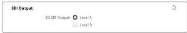
SDI Output
Some broadcast equipment can only receive level A or level B 3G-SDI video. To maintain compatibility with other broadcast equipment, select Level A for direct stream 3G-SDI or Level B for dual stream multiplexed 3G-SDI.
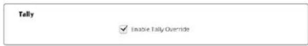
Tally
Select 'enable tally override' to enable tally borders on Blackmagic SmartView 4K G3. This feature is compatible with cameras including Blackmagic URSA Mini Pro 4.6K, URSA Mini Pro 12K and Blackmagic URSA Broadcast G2.
Connect the camera's SDI outputs to the ATEM switcher and to input 1 or 2 on your SmartView 4K G3. Connect the ATEM switcher's program output to the camera's SDI input.
When the ATEM switcher switches the camera to the program output, a red tally border will appear on you SmartView 4K G3. When switched to the preview output, the tally border will appear green.
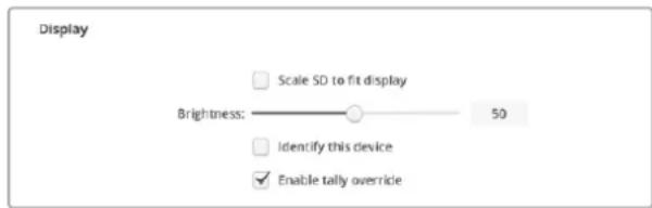
Display
When working with SD video, you can scale the video to fill the display by checking the the box.
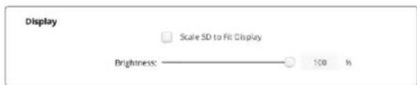
To adjust the brightness of the monitor, drag the slider control left or right or enter the brightness as a percentage in the number field.
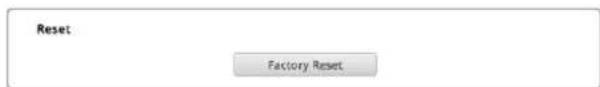
Reset
Click 'factory reset' to restore your SmartView 4K G3 to factory settings. Once you press 'set', you will be prompted to confirm your selection. To proceed, click 'reset'.
2110 Tab
The 2110 tab provides settings for routing SMPTE 2110 IP video streams along with PTP clock settings.
2110 Receiver Settings
Route incoming sources to your SmartView 4K G3 using the '2110 receiver' settings.
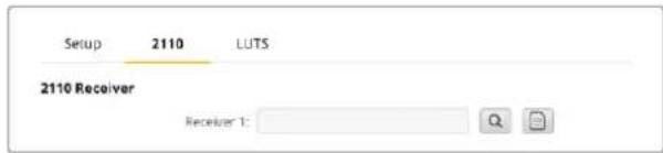
To route an incoming stream:
1 Click on the magnifying glass to the right of the receiver field. A window will appear listing the IP node and source label for all available 2110 IP streams on the network.
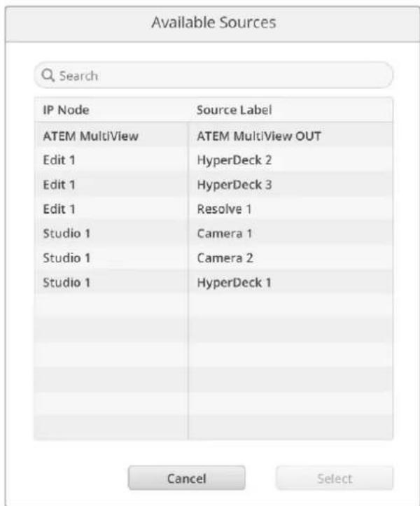
2 Select an available stream from the list and click the 'select' button. The window will close and return to the 2110 tab of the setup utility. You should now see the incoming source on the SmartView monitor.
PTP Clock Settings
The PTP settings let you configure the settings for the PTP grandmaster.
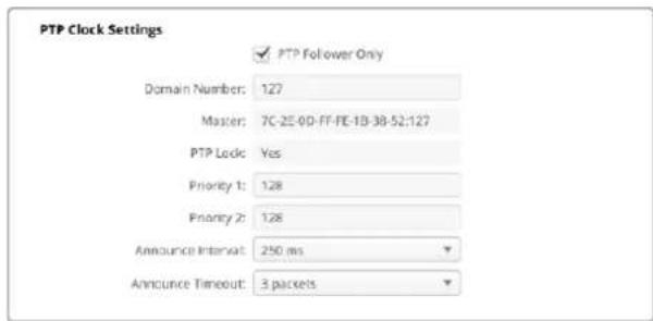
When connecting SmartView 4K G3 to a 10G network switch with a PTP grandmaster, the SmartView monitor needs to be set to 'PTP follower only' mode to prevent a timing conflict. If you have connected the monitor to another 2110 IP unit such as a Blackmagic 2110 IP 3x3G Converter, set one to be the follower by ticking the checkbox
Domain Number
Enter the domain number to match that of the PTP grandmaster. This is commonly 127 but can be changed by entering a different domain number in the field.
Master
The master address field displays the MAC address of the PTP grandmaster. This is either a separate grandmaster, or an IP converter such as Blackmagic 2110 IP Converter 3x3G.
PTP Lock
The PTP lock field will acknowledge when the monitor is locked to a PTP clock via Ethernet.
Priority
When the SmartView 4K G3 is not set to 'PTP follower only' it can become a PTP Master. The priority of the unit to become the master is set here. The lower the number the higher the priority.
Announce Interval and Timeout
The announce interval and timeout fields need to match the specifications of the PTP grandmaster which transmits sync messages typically every two seconds or 2000 ms. To change the frequency of the message, use the menu to select a different time. The ranges available for announce interval and announce timeout will depend on your PTP grandmaster.
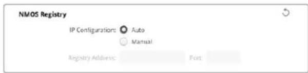
NMOS Registry
The NMOS registry IP can be entered manually or check auto to automatically discover the NMOS registry on the network.
LUTS Tab
SmartView 4K G3 lets you monitor your video using 3D LUTs. This gives you the option to calibrate your SmartView 4K G3 using professional calibration LUTs, or to view your video as close to your final grade as possible. You can also use 3D LUTs to experiment with different looks. LUTs are loaded into SmartView 4K G3 using Blackmagic SmartView Setup, and because SmartView 4K G3 supports industry standard LUT files with a .cube file extension, you can even load custom LUTs generated with DaVinci Resolve. Refer to the DaVinci Resolve manual for more information about generating LUT files.
To load a 3D LUT into 3D LUT 1:
1 Launch Blackmagic SmartView Setup.
2 Press the 'load LUT 1' load button. A window will open asking you for the location of the LUT file you want to load. Select the desired .cube LUT file, then press the 'open' button.
3 To view the LUT you just loaded, press the 3D LUT 1 button on the SmartView 4K G3's control panel. Press the button again to turn the LUT off.
Follow the same procedure to load a LUT file into 3D LUT 2.

Use Blackmagic SmartView Setup to load 3D LUTs on your SmartView 4K G3
SmartView and SmartScope Duo 4K
SmartView Duo and SmartScope Duo 4K are dual monitor units with two independent 8" LCDs. This lets you monitor two separate video signals simultaneously, or you can loop the same input to both screens. SmartView Duo supports up to HD 1080p30 and SmartScope Duo 4K supports all HD standards and frame rates plus Ultra HD video up to 2160p30. This section of the manual will show how to set up and change settings on your SmartView Duo or SmartScope Duo 4K.
Adjusting Monitor Settings
When launched, Blackmagic SmartView Setup will immediately search for any SmartView or SmartScope units connected via USB or Ethernet and display them in the SmartView Setup home page. If you have more than one Blackmagic monitor connected to your network, click on the left and right arrow icons on each side of the home page to select the monitor you want to adjust. If your Blackmagic monitor is connected via USB, a USB icon will appear next to the monitor name.
To adjust settings, select your monitor connected via Ethernet and USB, and click on the settings icon below the monitor name. This will open the settings page for your selected monitor. When you are happy with your settings, click the save button to save your settings and return to the SmartView Setup home page.
See the next section for information on settings that are available for Blackmagic monitors and how to apply them. For information on how to configure network settings using Blackmagic SmartView Setup, turn to the section "adjusting network settings".
Monitor Settings
To adjust settings and displays for each monitor, they must be connected via Ethernet or USB. Select the monitor you wish to set by clicking on the left and right arrow icons on the SmartView Setup home page, then clicking on the settings icon under your monitor name. The settings page is automatically customized to suit the features supported by your selected Blackmagic monitor.
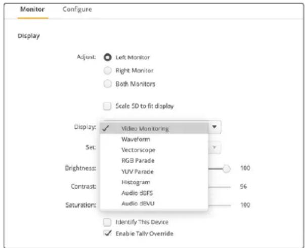
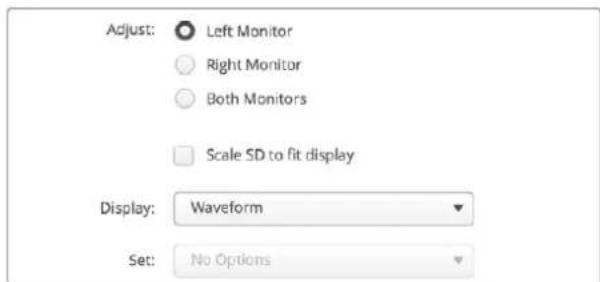
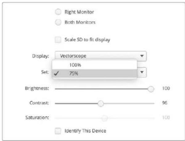
With SmartScope Duo 4K you can select between scopes or video monitoring from the 'display' drop down menu
Adjust
When using a SmartScope or SmartView Duo, choose the monitor you want to adjust by selecting 'left monitor', 'right monitor', or 'both monitors' to adjust both at the same time. When the 'both monitors' setting is enabled, any adjustments to brightness, contrast and saturation will be applied to both monitors on SmartView Duo and SmartScope.
Display
When using a SmartScope, the 'display' drop down menu provides selectable scopes. Select 'video monitoring' if you just want to see the video image.
Set
When using a SmartScope, the 'set' menu lets you select 4:3 or 16:9 aspect ratios for the video monitoring display when using standard definition video. The 'set' menu provides additional options for the selected display, including vectorscope, audio dBFS and audio dBVU options.
Video Monitoring: Select to view the video image using 4:3 or 16:9 aspect ratios.
When viewing widescreen anamorphic standard definition video, choose the 16:9 aspect ratio. When viewing traditional 4:3 standard definition video, choose the 4:3 aspect ratio.
- Vectorscope: Select whether your input is based on 100% or 75% color bar test signals.
Audio dBFS: Select which pair of audio channels to monitor phase.
Audio dBVU: Select which pair of audio channels to monitor phase.
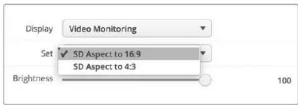
Set "SD Aspect to 16:9" when viewing anamorphic standard definition video
Brightness, Contrast and Saturation
Adjust the sliders to apply brightness, contrast and saturation settings. The settings available will differ between SmartView and SmartScope models.
Identify Monitor
When the 'identify' checkbox is enabled, any monitor selected in Blackmagic SmartView Setup will display a white border. If several SmartView and SmartScope units are connected via a network, this setting makes it easy to visually identify the selected monitor.
If this setting is used in conjunction with the 'both monitors' setting, the white border will be displayed on both SmartView Duo or SmartScope Duo 4K monitors.
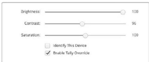
Drag the sliders left and right to adjust brightness, contrast and saturation settings. Check the setting to visually identify your selected monitor.
Enable Tally Override
Select 'enable tally override' to enable tally borders on Blackmagic SmartView Duo and SmartScope Duo 4K. This feature is compatible with Blackmagic cameras including Blackmagic URSA Mini Pro 4.6K G2 and Blackmagic URSA Broadcast G2.
Connect the camera's SDI output to input A or B on your SmartView Duo or SmartScope Due 4K.
Connect the ATEM switcher's program output to the camera's SDI input.
When the ATEM switcher switches the camera to the program output, a red tally border will appear on your SmartView Duo or SmartScope Duo 4K. When switched to the preview output, the tally border will appear green.
Click on the 'enable tally override' checkbox to display tally borders on SmartView Duo when connected to a Blackmagic URSA Mini Pro or URSA Broadcast camera
Using SmartScope Duo 4K
What is Blackmagic SmartScope?
Previously, broadcast quality television and post production scopes were incredibly expensive custom solutions that only let you see one scope at a time on a tiny screen! Some scopes look ugly and don't really look good in front of your client.
With SmartScope Duo 4K you get the addition of waveform monitors which allow you to see any aspect of your video signal on your dual monitors in real time. Any adjustments made to the input signal in Blackmagic SmartView Setup can immediately be seen on SmartScope Duo 4K! In addition, each input signal can be sent to either monitor via the SDI loop out, meaning you can use the right hand monitor to display the scope for the signal going into the left hand monitor.
The scopes displayed by SmartScope Duo 4K are selected in the Blackmagic SmartView Setup software. Select your scopes from the 'display' menu.
The information over the next several pages explains how each scope display is used so you can get a deeper understanding of how each display can help you.
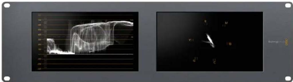
It's easy to set your Blackmagic SmartScope Duo 4K to show a different scope on each monitor using Blackmagic SmartView Setup
Video Monitoring Display
The video monitoring display is a handy confidence monitor so you can see the video that is being received by SmartScope.
If your input signal is SD, you can select between displaying it in either 4:3 pillarbox or 16:9 from the 'set' menu. Any changes made to the LCD brightness, contrast or saturation settings can be immediately seen in this view. Note that changing these settings only affects the monitor, not the video signal, so the scopes will not be affected by any saturation or brightness changes.
It can often be handy to set one monitor as 'video monitoring' and another as your scope view. To do this, use a short cable to connect the SDI loop out from 'monitor 1' to the SDI in of 'monitor 2'.
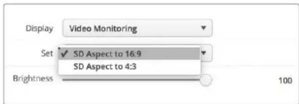
You can view SD video in 4:3 pillar box or 16:9 widenscreen by selecting from the 'set' options in Blackmagic SmartView Setup. Set 'SD aspect to 16:9' when viewing anamorphic standard definition video.

The video monitoring display setting shows the video signal as it will normally appear on a television screen or monitor.
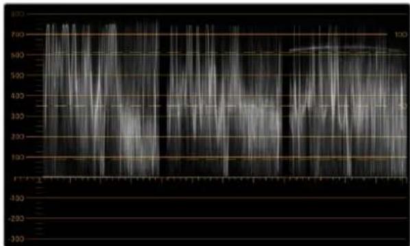
Waveform Display
The waveform display provides a digitally encoded waveform similar to traditional luminance waveform monitors, which is used to monitor and adjust the luma, or brightness, levels of your video signal.
Traditional luminance waveform monitors only supported composite analog standard definition video. However, SmartScope Duo 4K's waveform view works in Ultra HD and HD as well as SD so you have a consistent and easy way to adjust luma levels, even when monitoring high definition digital video formats!
Select waveform from the display drop down menu in Blackmagic SmartView Setup. You will want to make sure the blacks in your waveform do not drop below 0% and the whites do not exceed 100% as this means you are getting illegal luma values.
The waveform monitor is a graphical representation of the image, showing luma values in the same position relative to those within the frame. For example, if part of your sky is overexposed you will see it in the same horizontal position on the waveform display as it appears in the frame.
Depending on your footage, your waveform will look different. If you are monitoring video which is high contrast, you might not see any values in the mid grays. The picture below shows a waveform for an evenly exposed image with a dark patch on the left, and brighter values from the center of the frame out to the right.
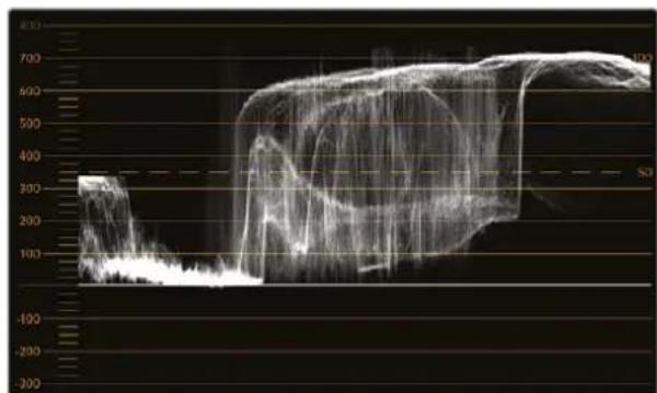
The waveform display showing luminance values
Select 'waveform' In Blackmagic SmartView Setup's display settings to view the luminance values in your video signal
Vectorscope Display
The vectorscope display uses a vector view to show the colors in a video signal. Depending on the standard of color bar test signals used in your facility, select either 100% or 75% from the 'set' menu in Blackmagic SmartView Setup.
Some people think you can use a vectorscope to check for illegal levels, however this is not correct. The Parade RGB display should be used for checking for illegal colors. The reason you cannot use a vectorscope to check for illegal levels is that both chroma and luminance values are required. For example, colors near the white or black points in video cannot be as saturated as the much stronger colors, which can be used in the mid grays. Because vectorscope display only shows colors, and not luminance values, it cannot be used solely to check for illegal colors.
Vectorscope display is the best tool for checking color levels from older, analog videotape where you need to adjust chroma levels. Just play back the color bar segment of the videotape, and then adjust the chroma and hue settings to set the colors of the video within the square boxes in the graticule.
Vectorscope display is also perfect for color grading, as you can easily see if your video is correctly white balanced or if there is a color tint. If your video has a color tint, the vectorscope display will drift off center, and you might see two center dots. Normally the blanking in the video signal will create a dot in the center of the vectorscope, and this is because the blanking in the video is black video without any color. Blanking provides a useful reference point to help recognize areas of black video without any color information.
If your video has a color tint, you should see the blacks move off color and off center. The degree of shift represents the amount of color tint in your video and you can see the shift in both the white and black details of your video. This makes vectorscope display valuable for removing color tint and regaining correct white balance.
Vectorscope display lets you push colors in your video to the limits, without accidentally adding unwanted color tints to blacks and whites. While color balance can be monitored on both the RGB parade display and vectorscope display, color balance issues will often be easier to see in the vectorscope display.
When color correcting footage of skin tone, particularly faces, you will want to keep your warm color saturation along a line at approximately 10 o'clock on the vectorscope. This is known as the "fleshtone line" and is based on the color of blood beneath the skin's surface. The fleshtone line is therefore applicable to all skin pigmertations and is the best way to ensure the skin tones of your talent look natural.
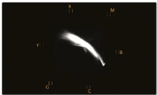
Vectorscope display showing the "fleshtone line" towards the 10 o'clock position
Set your vectorscope to 100% or 75% color bar test signals
Parade Display
RGB and YUV parade displays are perfect for color correction, checking for illegal colors and checking levels.
When color correcting, select RGB parade from the 'display' menu in Blackmagic SmartView Setup. RGB parade view displays the full height of the individual red, green and blue color channels. Monitoring the levels of each color channel makes color correction straightforward and it is also easy to view color balance in the blacks, mids and whites of the video signal. RGB parade display enables you to identify details common to the red, green and blue channels, making it simple to color balance and remove unwanted color tints.
It's important when color correcting to make sure the video levels are full but not clipped. If you want to increase the video level, make sure it doesn't go above upper RGB limit or you will encounter illegal levels. Some equipment won't let you generate illegal 100% RGB levels, however other equipment will. SmartScope Duo 4K lets you see illegal levels whenever they occur.
Illegal video can also happen in the black and white levels. In some color correction systems, black levels can be lowered to below the black point of 0% . If you observe illegal black levels, just add some "lift" or gain to eliminate them but check the 100% graticule level to make sure the whole video signal has not lifted and generated illegal colors in the whites.
To check YUV levels, select YUV parade from the 'display' menu. This view is useful because the luma, or brightness, values are separated from the chroma, or color values, which is the format of video signals for television broadcast. The left waveform shows the luma information and the second and third waveforms show the chroma information. YUV parade view is useful for calibrating a video signal's chroma values to a color bar test pattern, so that colors are represented accurately and the signal being broadcast will be displayable by television sets.
Color correcting is a constant adjustment process to attain the best looking images without generating illegal levels!
Color Correction Terminology
Blacks - Black levels in the video signal
Mids - Mid gray levels in the video signal
Whites - White levels in the video signal
RGB parade view
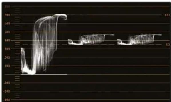
YUV parade view
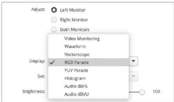
Select between RGB parade and YUV parade from the 'display' menu in Blackmagic SmartView Setup
Histogram Display
Histogram display is most familiar to graphic designers and camera operators. Histogram display shows the distribution of white to black information and lets you monitor how close the detail is to being clipped off in the whites or blacks of the video. Histogram display also lets you see the effects of gamma changes in the video.
Black video is shown on the left of the display, and whites are shown on the right. All video should usually be found between the 0% and 100% intervals of the histogram display. Your video is being clipped if it moves below 0% or above 100% . Video clipping can be really bad when you're on a shoot, as detail in the blacks and whites must be preserved if you subsequently want to perform color-correction in a controlled environment. When shooting, keep the video above the black clip, and below the white clip, so you can have more freedom later to adjust colors without whites and blacks appearing flat and lacking in detail.
When color-correcting, you might decide to clip your video, and in which case histogram display will show the effect of clipping the video, and how much it is being clipped. You can even use gamma to create a similar look, with less clipping, while retaining more detail.
You cannot really use histogram display to check for illegal levels although you can use it to see illegal blacks and whites. Histogram display does not show colors and so the histogram might appear to show legal levels, even though your video may contain illegal colors. Again, RGB parade display provides the best way to watch out for illegal levels as it shows them in both the color and luminance elements of the video signal.
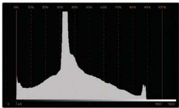
The histogram display setting showing distribution of whites to blacks
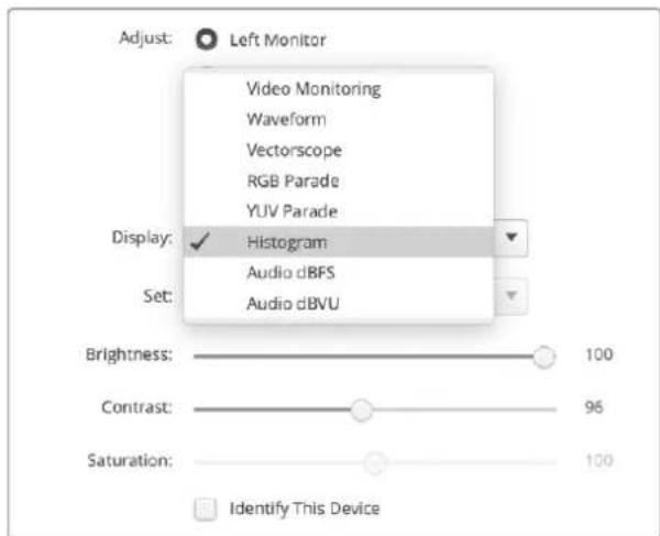
Select histogram from the 'display' menu in Blackmagic SmartView Setup
Audio Metering Display
The audio metering displays show you the audio levels in the embedded audio of the SDI video signal. Up to 16 channels of embedded audio are de-embedded and then displayed in either dBVU or dBFS format.
The VU meter shows average signal levels, is easy to use and very common on older equipment. VU is calibrated to the SMPTE recommendation of a 1 kHz tone test signal set to -20 dBFS.
dBFS is essentially a meter of the overall digital audio signal and is common on modern digital equipment.
The right hand audio scope can monitor two channels of audio, which can be selected from the 'set' menu. e.g., ch 1 & 2, ch 3 & 4, etc. The audio scope presents audio in an X-Y view so you can see audio balance issues, out of phase conditions and whether an audio track is mono or stereo. Mono audio should appear as a single vertical "in phase" line. If the line is horizontal, then your audio is "out of phase" and could cancel out resulting in a loss of audio received by downstream equipment. Audio phase is one of the most common audio faults in large facilities, where cables can be incorrectly connected.
When monitoring stereo signals, the line of the right hand audio scope fans out to represent the difference between the left and right audio channels. The more stereo sound contained in the audio track, the more circular the line will appear. If the audio contains minimal stereo content, then the scope will appear more concentrated around the vertical axis.
Dialog audio tends to appear as a vertical line, whereas music with plenty of stereo content will cause the scope to puff out. This is because mono audio is L + R , and will display on the vertical axis, whereas stereo content is L-R, and will display on the horizontal axis to show the stereo difference.
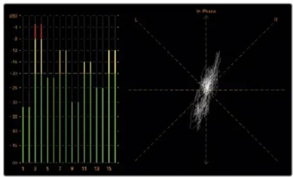
Audio metering display showing peak levels and audio balance
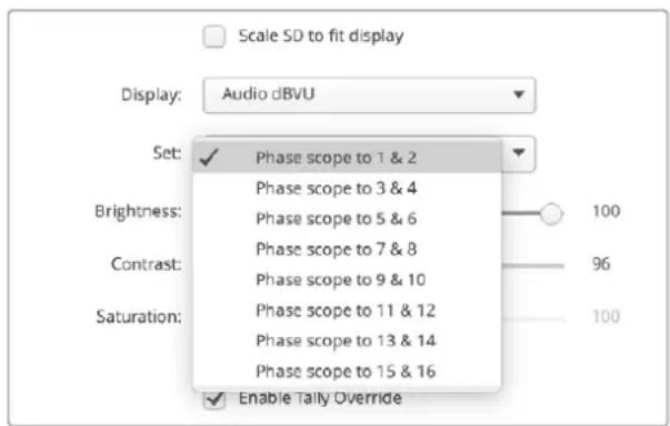
Use the "Set" menu to select which pair of audio channels to monitor
Network Settings
Monitor Name
It is a good idea to change your monitor's name so each SmartView Duo or SmartScope Duo unit is easy to identify on a network, e.g., "Field Cameras 1 & 2", "Multi-View Output", "4K feeds" etc.
To change your monitor's name, make sure your monitor is connected via Ethernet or USB. Launch Blackmagic SmartView Setup and click on the settings icon under your monitor name. Using the 'configure' tab edit the name of your monitor located in the 'details' section. If the software detects an invalid name, a warning icon will appear next to the name as you are typing. If the name is valid, a tick will appear. Press the 'return' key on your computer keyboard to confirm the name change.
Network Settings
To make changes to the network settings section in Blackmagic SmartView Setup, your Blackmagic monitor must be connected to the computer via USB. Network settings cannot be changed via Ethernet.
By default, SmartView Duo and SmartScope Duo use DHCP to automatically obtain an IP address from your network. If no SmartView or SmartScope monitors are found on the network, the units might not have received IP addresses via DHCP and it will be necessary to manually configure each unit with appropriate network settings.
To set a static IP address:
1 Connect a Blackmagic SmartView Duo or SmartScope Duo monitor to your computer via USB and launch Blackmagic SmartView Setup.
2 Your connected monitor will be automatically displayed in the SmartView Setup home page and will show a USB icon next to its name. Click on the monitor image.
3 Click the 'static IP' checkbox and fill in the IP address and gateway address fields. Please ask your system administrator for a spare IP address to avoid creating an IP conflict on your network.
4 Once you've entered the address details, click 'save'.
Connecting to a Network
By connecting a SmartView or SmartScope monitor to a network, you can adjust monitor settings for multiple units remotely.
While SmartView and SmartScope monitors display video without needing any configuration, any network settings need to be configured prior to deployment. Network configuration can only be performed using a direct USB connection to a computer.
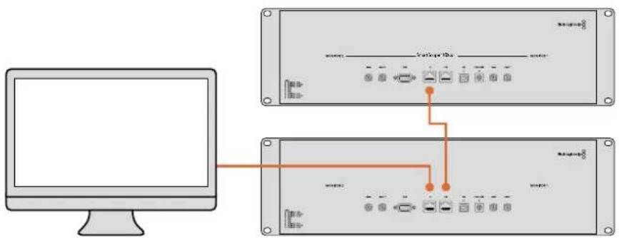
Direct Ethernet
Remote monitor configuration can be performed via a direct Ethernet connection to your computer. No network switch is required in this configuration, which is great if you need to install and set up quickly. Additional units can be daisy chained together using the active loop through Ethernet out port on each unit. Power must be supplied to all units in the chain.
If you want to connect several units without using IP addresses from your existing studio network, or if you don't have an existing network, simply connect them directly to the Ethernet port on your computer. This is also a fast way to connect SmartView and SmartScope units via Ethernet as you don't need to run any cables back to a network switch.
Direct Ethernet Connection Diagram
You can connect the Ethernet port of a computer directly to a unit without needing a network switch. Additional units can be daisy chained to each other so you don't have to run multiple cables back to a network switch. Power must be supplied to all units.
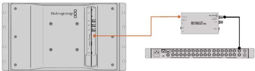
Point to Point 2110 IP Connection Diagram
SmartView 4K G3 can be connected point to point to Blackmagic 2110 IP converters to receive 2110 IP streams. In the following diagram, the ATEM switcher multiview output is connected to Blackmagic 2110 IP Mini BiDirect 12G via SDI. The converter is then connected to the SmartView 4K G3 via Ethernet.
Ethernet Network Switch
If you want to connect several units to your studio's network, you only need to connect one SmartView or SmartScope to the network switch and the rest can be daisy chained to each other using the active loop through Ethernet out port on each unit so only a single port on your switch is used. This way you won't have to run multiple cables back to a network switch. Power must be supplied to all units for daisy chained to work.
Connecting to a network switch allows any computer on the network to change a unit's settings. Any Mac or Windows laptop computer can also change settings via a WiFi connection if your network includes a wireless access point.
You will need to carry out the following steps to connect SmartView or SmartScope to a local area IP based network.
1 Securely connect and switch on the power supply included with your unit.
2 Connect the unit to a network switch, or directly to a computer, with a standard RJ45 Ethernet cable.
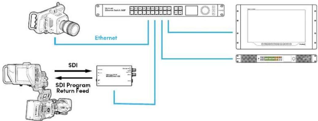
Connecting SmartView 4K G3 to a 2110 IP Network
Adding your SmartView 4K G3 to a 2110 IP network allows you to receive streams from 2110 IP converters along with studio cameras on the network. In the following diagram a SmartView 4K G3 is connected to a Blackmagic Ethernet Switch 360P. Also connected to the network switch are a Studio Camera 6K Pro, Audio Monitor 12G G3 and a Blackmagic 2110 IP Mini BiDirect 12G connected to an URSA camera. Once the cameras are recording, you can use the SmartView Setup utility to route the 2110 IP stream from the studio camera or the Mini 2110 IP converter.
Using Tally
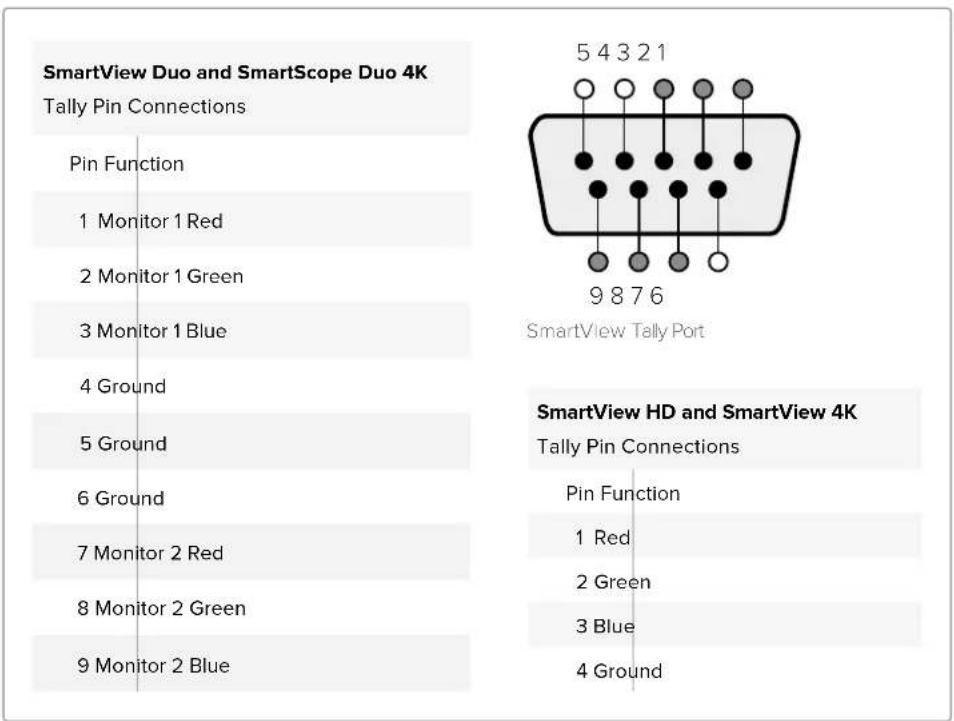
Tally Port Pin Connections
It is not necessary to connect the tally port of SmartView or SmartScope and you can skip this section if you do not intend to use the tally feature.
Each SmartView and SmartScope screen features independent tally borders in red, green or blue which can be used to indicate the status of a video signal such as on air, preview or recording.
The 9 pin D-sub tally port accepts contact closure signals from switchers and automation systems. Please refer to the accompanying tally pin connections diagram for information about wiring the tally port for use with your switcher or automation system.
The 9 pin D port wiring description is printed on the rear of the unit showing contact closures to display red, green or blue tally borders on each independent monitor.
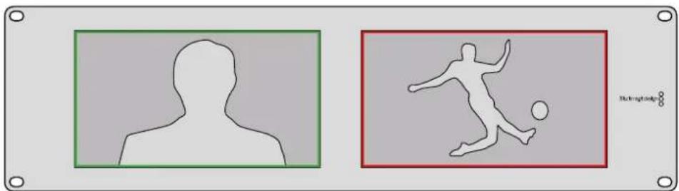
SmartView Duo showing green and red tally borders
Optimizing the Viewing Angle
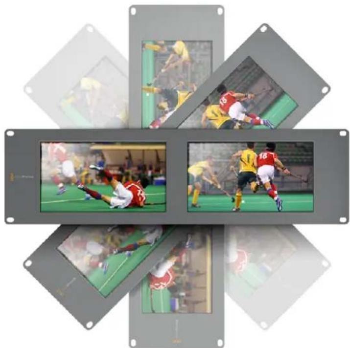
If SmartView Duo and SmartScope Duo 4K monitors are to be installed high up in an equipment rack, you may wish to physically invert the LCDs for the optimum viewing angle. The images on the LCDs will automatically flip to the correct orientation when they sense an inversion. A number 02 size pozidriv screwdriver is required to disconnect and reconnect the faceplate from its rear assembly. This is a simple procedure and does not involve opening the rear assembly.
The following procedure describes how to invert the unit while keeping the Blackmagic Design logo in the correct orientation on the faceplate. A number 02 size pozidriv screwdriver is required.
1 Remove the screws from the top, bottom, left and right sides of the faceplate. SmartView Duo and SmartScope Duo 4K have 10 screws.
2 Lift the front faceplate away from the rear assembly as illustrated.
3 Invert the rear assembly.
4 Reinstate the faceplate on the inverted rear assembly.
5 Reinstate the screws in the chassis.
Your SmartView Duo or SmartScope Duo 4K is now ready to be installed high up in a rack. Once bolted into a rack, your monitor will continue to display the optimum viewing angle even if bumped, as there are no external knobs or adjustments to mishandle or to come loose.
You may wish to perform a test inversion to check the optimum viewing angle before bolting your unit high up in a rack.
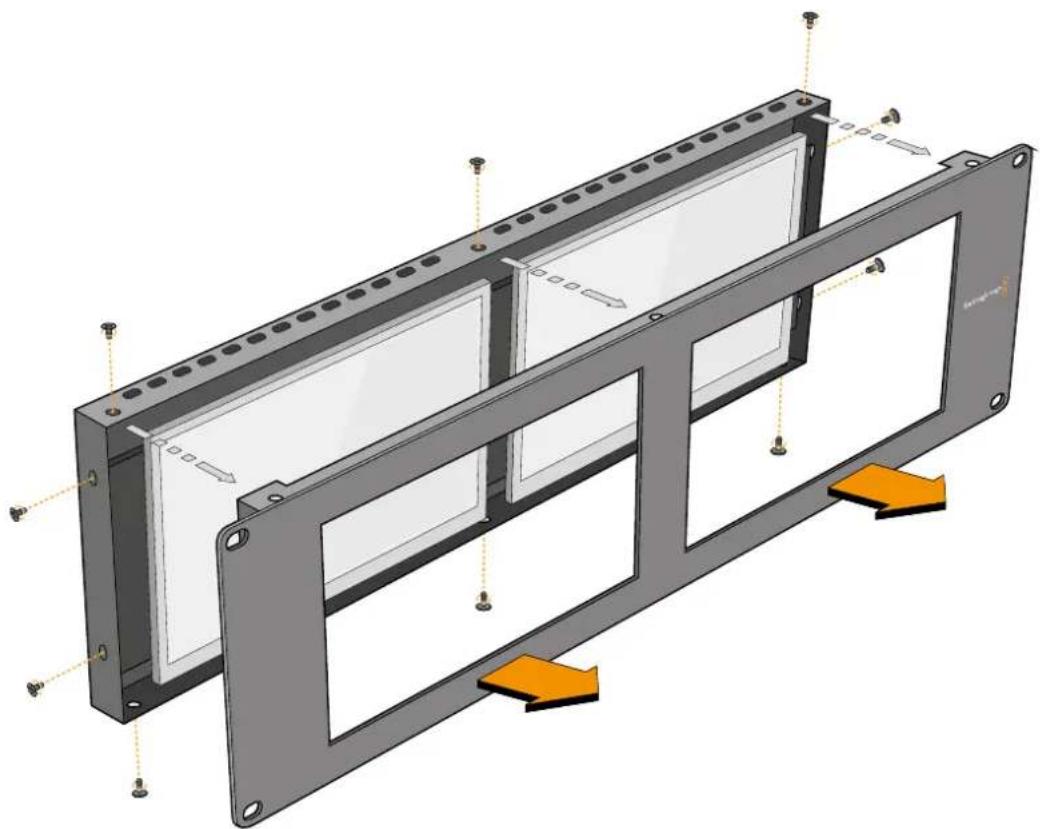
Remove all the screws to lift the front faceplate away from the rear assembly
Developer Information
Blackmagic 2K Format - Overview
Blackmagic Design products support 3G-SDI video, which allows twice the data rate of traditional HD-SDI video. We thought it would be a really nice idea to add 2K film support, via 3G-SDI technology, so we could simplify feature film workflows. With the popularity of Blackmagic Design editing systems worldwide, now thousands of people can benefit from a feature film workflow revolution.
This information includes everything product developers need to know for building native 2K SDI equipment. Of course, all Blackmagic products can be updated, so if the television industry adopts an alternative SDI-based film standard, we can add support for that too!
Frame Structure
- Transmitted at 23.98, 24 or 25 frames per second as a Progressive Segmented Frame.
Active video is 2048 pixels wide by 1556 lines deep.
Total lines per frame : 1650 - Active words per line are 1535. One word consists of a 10-bit sample for each of the four data streams, i.e., a total of 40 bits. See the diagram named Blackmagic 2K Format - Data Stream Format.
Total active lines: 1556
Total words per line: 1875 for 23.98/24Hz and 1800 for 25Hz.
Fields per frame: 2, 825 lines each
Active lines located on lines 16-793 (field 1) and 841-1618 (field 2).
Transport Structure
- Based on SMPTE 372M Dual Link mapping and SMPTE 425M-B support for mapping SMPTE 372M into a single 3 Gb/s link.
- Timing reference signals, line number and line CRC insertion is the same as above.
- During active video, 10-bit Red, Green and Blue data is sent in the following sequence:
- Optional ancillary data is inserted into both virtual interfaces.
-
At present, only audio data is included: as per standard HD audio insertion (SMPTE S299M) the audio data packets are carried on data stream two and audio control packets are carried on data stream one.
-
Data stream 1: Green_1, Green_2, Green_3, Green_5...Green_2047
- Data stream 2: Blue_1, Blue_2, Green_4, Blue_5...Green_2048.
- Data stream 3: Red_1, Blue_3, Blue_4, Red_5...Blue_2048.
Data stream 4: Red_2, Red_3, Red_4, Red_6...Red_2048.
Blackmagic 2K Format - Vertical Timing Reference
This diagram shows the vertical timing details with line numbers and Field, Vertical and Horizontal bits for the Timing Reference Signal codes.
| Field 1 Active | ||||||||||||
| F1000 | 0000 | 000 | ||||||||||
| V11111 | 0000 | 11 | ||||||||||
| LINE # | 1650 | 1 | 2 | ... | 14 | 15 | 16 | ... | 792 | 793 | ... | 825 |
| Field 2 Active | ||||||||||||
| F | 0 | 1 | 1 | 1 | 1 | 1 | 1 | 1 | 1 | 1 | 1 | 1 |
| V | 1 | 1 | 1 | 1 | 1 | 1 | 0 | 0 | 0 | 0 | 1 | 1 |
| LINE # | 825 | 826 | 827 | ... | 839 | 840 | 841 | ... | 1617 | 1618 | ... | 1650 |
Blackmagic 2K Format - Data Stream Format
This diagram shows the data stream formats around the optional ancillary data section of the horizontal line. Note that each active pixel takes up three samples.
| Word#25 PsF | Word#23.98/24 PsF | Data Stream 4 | Data Stream 3 | Data Stream 2 | Data Stream 1 |
| 1795 | 1870 | R2042 | R2041 | B2041 | G2041 |
| 1796 | 1871 | R2043 | B2043 | B2042 | G2042 |
| 1797 | 1872 | R2044 | B2044 | G2044 | G2043 |
| 1798 | 1873 | R2046 | R2045 | B2045 | G2045 |
| 1799 | 1874 | R2047 | B2047 | B2046 | G2046 |
| 1800 | 1875 | R2048 | B2048 | G2048 | G2047 |
| 1 | 1 | EAV(3FFh) | EAV(3FFh) | EAV(3FFh) | EAV(3FFh) |
| 2 | 2 | EAV(000h) | EAV(000h) | EAV(000h) | EAV(000h) |
| 3 | 3 | EAV(000h) | EAV(000h) | EAV(000h) | EAV(000h) |
| 4 | 4 | EAV(XYZh) | EAV(XYZh) | EAV(XYZh) | EAV(XYZh) |
| 5 | 5 | LNO | LNO | LNO | LNO |
| 6 | 6 | LN1 | LN1 | LN1 | LN1 |
| 7 | 7 | CRCO | CRCO | CRCO | CRCO |
| 8 | 8 | CRC1 | CRC1 | CRC1 | CRC1 |
| 9 | 9 | 200 | 040 | ANC/Audio Data | ANC/Audio Data |
| ... | ... | ... | ... | ||
| 260 | 335 | 200 | 040 | ||
| 261 | 336 | SAV(3FFh) | SAV(3FFh) | SAV(3FFh) | SAV(3FFh) |
| 262 | 337 | SAV(000h) | SAV(000h) | SAV(000h) | SAV(000h) |
| 263 | 338 | SAV(000h) | SAV(000h) | SAV(000h) | SAV(000h) |
| 264 | 339 | SAV(XYZh) | SAV(XYZh) | SAV(XYZh) | SAV(XYZh) |
| 265 | 340 | R2 | R1 | B1 | G1 |
| 266 | 341 | R3 | B3 | B2 | G2 |
| 267 | 342 | R4 | B4 | G4 | G3 |
| 268 | 343 | R6 | R5 | B5 | G5 |
Blackmagic SmartView Ethernet Protocol v1.4
Summary
The Blackmagic SmartView Ethernet Protocol is a text-based status and control protocol, very similar in structure to the Videohub protocol, that is accessed by connecting to TCP port 9992 on a SmartView or SmartScope monitor.
Upon connection, the SmartView or SmartScope monitor sends a complete dump of the state of the monitor. After the initial dump, state changes are sent asynchronously.
The SmartView or SmartScope sends information in blocks which have an identifying header, followed by a colon. A block can span multiple lines and is terminated by a blank line.
To be resilient to future protocol changes, clients should ignore blocks they do not recognize, up to the trailing blank line. Within recognized blocks, clients should ignore lines they do not recognize.
Legend
carriage return
and so on
Version 1.4 of the Blackmagic SmartView Ethernet
Protocol was released with SmartView 1.4 software.
Protocol Preamble
The first block sent by the SmartView Server is always the protocol preamble:
PROTOCOL PREAMBLE:
Version: 1.4
The version field indicates the protocol version. When the protocol is changed in a compatible way, the minor version number will be updated. If incompatible changes are made, the major version number will be updated.
Device Information
The next block contains general information about the connected SmartView or SmartScope.
SMARTVIEW DEVICE:←
Model:SmartView Duo
Hostname: stagefront studio.example.com
Name:StageFront
Monitors: 2
Inverted: false
This example shows the output for a SmartView Duo, which has two LCDs.
The INVERTED flag indicates whether the monitor has detected that it has been mounted in an inverted configuration to optimize LCD viewing angle.
Network Configuration
The next block shows the TCP/IP networking configuration:
NETWORK:
Dynamic IP: true
Static address: 192.168.2.2
Static n etm ask: 255.255.255.0
St atic g atew ay: 192.168.241
C u r rent add r ess: 192.168.1.101
C u r rent n etm ask: 255.255.265.0
C u r rent gate w ay: 192.168.1.1
The network settings prefixed with CURRENT show the active TCP/IP settings, and are readily. The CURRENT settings reflect either the DHCP or Static configuration, depending on the DYNAMIC IP flag.
Changing Networking Settings
The network can be configured to use either DHCP or a static configuration. To enable DHCP:
NETWORK:
Dynamic IP: true
←
To set a fixed IP address, supply all static parameters, thus:
NETWORK:
Dynamic IP: false
Static address: 192.168.2.2
Static n etm ask: 255.255.255.e1
St atic g atew ay: 192.168.241
The parameters with the CURRENT prefix are read-only, and show the active configuration, regardless of the static or dynamic setting.
Changing the name, or any network settings, will cause the IP connection to be dropped. The SmartView or SmartScope will restart its networking and advertise its new name on the network.
Changing Monitor Settings
The display settings for each monitor are specified individually. One or more parameters can be modified at the same time and multiple settings can be supplied in one block.
The valid range for numeric values is 0-255. The CONTRAST and SATURATION properties are zero-centered, so the normal value is 127, such that the displayed picture is the same as the original. A value greater than 127 in either channel will cause the contrast or saturation to be increased, and similarly a value less than 127 will cause a decrease.
For example, to set the brightness to 50% and desaturate the image to Black & White:
MONITOR A: Brightness: 127 Saturation: 0
Displaying SD in 16:9
The following command sets standard definition video to display in 16:9:
MONITOR A:
WidescreenSD:ON
Displaying SD in 4:3
The following command sets standard definition video to display in 4:3:
MONITOR A:
WidescreenSD: OFF
Identification and Tally Settings
The Identify flag is transient, and will cause a white border to be displayed around the entire picture for a duration of 15 seconds, after which it will be reset. This feature is primarily aimed at identifying which monitor is currently being configured when it is mounted in a rack comprising multiple units. To turn on:
MONITOR A:
Identify: trale
The IDENTIFY border will temporarily override any other border setting in effect.
The BORDER property can be used to programmatically set the soft Tally colored borders to one of the primary colors: RED, GREEN, BLUE, WHITE or NONE. This setting can be overridden by the electrical Tally signals at the DB-9 input on the monitor itself. For example, to set the soft Tally to green:
MONITOR B:
Border:green
The hard wired tally will always override the soft tally. The full state report will always show the current valid border.
SmartScope Settings
On SmartScope Duo 4K, each monitor can be set to display a different scope. The values for activating specific scopes are mapped as follows:
AudioDbfs
AudioDbvu
Histogram
ParadeRGB
ParadeYUV
Picture (This is the same as Video Monitor)
Vector100
Vector75
WaveformLuma
MONITOR A:
ScopeMode: Picture
In the example above, Monitor A has been set as a video monitor.
Displaying SD in 16:9
The set Video Monitor mode to display standard definition video in 16:9:
MOTOR A:ScopeMode:Picture WidescreenSD:ON
Displaying SD in 4:3
To set Video Monitor mode to display standard definition video in 4:3:
MOTOR A:ScopeMode:Picture WidescreenSD:OFF
When setting one of SmartScope Duo 4K's monitors to audio metering, you can also select which channels to show. The values for selecting which audio channels are mapped in the following way:
0: Channels 1 and 2
1: Channels 3 and 4
2: Channels 5 and 6
3: Channels 7 and 8
4: Channels 9 and 10
5: Channels 11 and 12
6: Channels 13 and 14
7: Channels 15 and 16
MOTOR B:ScopeMode: AudioDbvuAudioChannel:0
In the example above, Monitor B has been selected to display Audio Metering in Dbvu with audio channels 1 and 2 selected for the phase meter.
Selecting LUTs for SmartView 4K
To select 3D LUTs using SmartView 4K:
MONITOR A: LUT: 0 LUT 1 1 LUT 2 NONE DISABLE
Help
Getting Help
There are four Steps to Getting Help.
1 Check out the Blackmagic Design support center at www.blackmagicdesign.com/support for the latest support information.
2 Call your Blackmagic Design reseller.
3 Your local reseller will have the latest technical updates from Blackmagic Design and should be able to give you immediate assistance. We also recommend you check out the support options your reseller offers as they can arrange various support plans based on your workflow requirements.
4 The next option is to email us with your questions using the "send us an email" button at www.blackmagicdesign.com/support
5 Phone a Blackmagic Design support office. You can find your nearest office by clicking on the "find your local support team" button at the bottom of the support page.
Please provide us with as much information as possible regarding your technical problem and system specifications so that we may try to respond to your problem as quickly as possible.
Regulatory Notices
Disposal of Waste of Electrical and Electronic Equipment Within the European Union.

The symbol on the product indicates that this equipment must not be disposed of with other waste materials. In order to dispose of your waste equipment, it must be handed over to a designated collection point for recycling. The separate collection and recycling of your waste equipment at the time of disposal will help conserve natural resources and ensure that it is recycled in a manner that protects human health and the environment. For more information about where you can drop off your waste equipment for recycling, please contact your local city recycling office or the dealer from whom you purchased the product.

This equipment has been tested and found to comply with the limits for a Class A digital device, pursuant to Part 15 of the FCC rules. These limits are designed to provide reasonable protection against harmful interference when the equipment is operated in a commercial environment. This equipment generates, uses, and can radiate radio frequency energy and, if not installed and used in accordance with the instructions, may cause harmful interference to radio communications. Operation of this product in a residential area is likely to cause harmful interference, in which case the user will be required to correct the interference at personal expense.
Operation is subject to the following two conditions:
1 This device may not cause harmful interference.
2 This device must accept any interference received, including interference that may cause undesired operation.

P-REM-BMD-201410001
MSIP-REM-BMD-20150327
MSIP-REM-BMD-201702004
MSIP-REM-BMD-201702005
R-R-BMD-20240212003
ISED Canada Statement
This device complies with Canadian standards for Class A digital apparatus.
Any modifications or use of this product outside its intended use could void compliance to these standards.
Connection to HDMI interfaces must be made with high quality shielded HDMI cables.
This equipment has been tested for compliance with the intended use in a commercial environment. If the equipment is used in a domestic environment, it may cause radio interference.
Safety Information
For protection against electric shock, the equipment must be connected to a mains socket outlet with a protective earth connection. In case of doubt contact a qualified electrician.
To reduce the risk of electric shock, do not expose this equipment to dripping or splashing.
Product is suitable for use in tropical locations with an ambient temperature of up to 40^
Ensure that adequate ventilation is provided around the product and that it is not restricted.
When rack mounting, ensure that the ventilation is not restricted by adjacent equipment.
No operator serviceable parts inside product. Refer servicing to your local Blackmagic Design service center.
Some products have the facility to connect small form-factor transceiver (SFP) optical fibre modules. Only use Laser class 1 optical SFP modules.
Recommended Blackmagic Design SFP modules:
3G-SDI:PL-4F20-311C
- 6G-SDI: PL-8F10-311C
12G-SDI:PL-TG10-311C

Use only at altitudes not more than 2000m above sea level.
State of California statement
This product can expose you to chemicals such as trace amounts of polybrominated biphenyls within plastic parts, which is known to the state of California to cause cancer and birth defects or other reproductive harm.
For more information go to www.P65Warnings.ca.gov.
European Office
Blackmagic Design Europe B.V.
Rijnlanderweg 766, Unit D
2132 NM Hoofddorp
NL
Warranty
12 Month Limited Warranty
Blackmagic Design warrants that this product will be free from defects in materials and workmanship for a period of 12 months from the date of purchase. If a product proves to be defective during this warranty period, Blackmagic Design, at its option, either will repair the defective product without charge for parts and labor, or will provide a replacement in exchange for the defective product.
In order to obtain service under this warranty, you the Customer, must notify Blackmagic Design of the defect before the expiration of the warranty period and make suitable arrangements for the performance of service. The Customer shall be responsible for packaging and shipping the defective product to a designated service center nominated by Blackmagic Design, with shipping charges pre paid. Customer shall be responsible for paying all shipping charges, insurance, duties, taxes, and any other charges for products returned to us for any reason.
This warranty shall not apply to any defect, failure or damage caused by improper use or improper or inadequate maintenance and care. Blackmagic Design shall not be obligated to furnish service under this warranty: a) to repair damage resulting from attempts by personnel other than Blackmagic Design representatives to install, repair or service the product, b) to repair damage resulting from improper use or connection to incompatible equipment, c) to repair any damage or malfunction caused by the use of non Blackmagic Design parts or supplies, or d) to service a product that has been modified or integrated with other products when the effect of such a modification or integration increases the time or difficulty of servicing the product. THIS WARRANTY IS GIVEN BY BLACKMAGIC DESIGN IN LIEU OF ANY OTHER WARRANTYES, EXPRESS OR IMPLIED. BLACKMAGIC DESIGN AND ITS VENDORS DISCLAIM ANY IMPLIED WARRANTYES OF MERCHANTABILITY OR FITNESS FOR A PARTICULAR PURPOSE. BLACKMAGIC DESIGN'S RESPONSIBILITY TO REPAIR OR REPLACE DEFECTIVE PRODUCTS IS THE WHOLE AND EXCLUSIVE REMEDY PROVIDED TO THE CUSTOMER FOR ANY INDIRECT, SPECIAL, INCIDENTAL OR CONSEQUENTIAL DAMAGES IRRESPECTIVE OF WHETHER BLACKMAGIC DESIGN OR THE VENDOR HAS ADVANCE NOTICE OF THE POSSIBILITY OF SUCH DAMAGES. BLACKMAGIC DESIGN IS NOT LIABLE FOR ANY ILLEGAL USE OF EQUIPMENT BY CUSTOMER. BLACKMAGIC IS NOT LIABLE FOR ANY DAMAGES RESULTING FROM USE OF THIS PRODUCT. USER OPERATES THIS PRODUCT AT OWN RISK.
Copyright 2024 Blackmagic Design. All rights reserved. 'Blackmagic Design', 'DeckLink', 'HDLink', 'Workgroup Videohub', 'Multibridge Pro', 'Multibridge Extreme', 'Intensity' and 'Leading the creative video revolution' are registered trademarks in the US and other countries. All other company and product names may be trade marks of their respective companies with which they are associated.
Blackmagic
SmartView SmartScope


又如乙
Blackmagic Design CEO
glarnt-
目次

InstallSmartView 5.0

Uninstall SmartView
Blackmagics

MAC Address (MACADSL)
NMOS Registry (NMOSLeJstU)
Blackmagic Design products support 3G-SDI video, which allows twice the data rate of traditional HD-SDI video. We thought it would be a really nice idea to add 2K film support, via 3G-SDI technology, so we could simplify feature film workflows. With the popularity of Blackmagic Design editing systems worldwide, now thousands of people can benefit from a feature film workflow revolution.
This information includes everything product developers need to know for building native 2K SDI equipment. Of course, all Blackmagic products can be updated, so if the television industry adopts an alternative SDI-based film standard, we can add support for that too!
Frame Structure
- Transmitted at 23.98, 24 or 25 frames per second as a Progressive Segmented Frame.
Active video is 2048 pixels wide by 1556 lines deep.
Total lines per frame:1650 - Active words per line are 1535. One word consists of a 10-bit sample for each of the four data streams, i.e., a total of 40 bits. See the diagram named Blackmagic 2K Format - Data Stream Format.
Total active lines: 1556
Total words per line: 1875 for 23.98/24Hz and 1800 for 25Hz.
Fields per frame: 2, 825 lines each
Active lines located on lines 16-793 (field 1) and 841-1618 (field 2).
Transport Structure
- Based on SMPTE 372M Dual Link mapping and SMPTE 425M-B support for mapping SMPTE 372M into a single 3 Gb/s link.
- Timing reference signals, line number and line CRC insertion is the same as above.
- During active video, 10-bit Red, Green and Blue data is sent in the following sequence:
- Optional ancillary data is inserted into both virtual interfaces.
- At present, only audio data is included: as per standard HD audio insertion (SMPTE S299M) the audio data packets are carried on data stream two and audio control packets are carried on data stream one.
Data stream 1: Green_1, Green_2, Green_3, Green_5...Green_2047
- Data stream 2: Blue_1, Blue_2, Green_4, Blue_5...Green_2048.
- Data stream 3: Red_1, Blue_3, Blue_4, Red_5...Blue_2048.
Data stream 4: Red_2, Red_3, Red_4, Red_6...Red_2048.
Blackmagic 2K Format - Vertical Timing Reference
This diagram shows the vertical timing details with line numbers and Field, Vertical and Horizontal bits for the Timing Reference Signal codes.
| Field 1 Active | ||||||||||||
| F1000 | 0000 | 000 | ||||||||||
| V11111 | 0000 | 11 | ||||||||||
| LINE # | 1650 | 1 | 2 | ... | 14 | 15 | 16 | ... | 792 | 793 | ... | 825 |
| Field 2 Active | ||||||||||||
| F | 0 | 1 | 1 | 1 | 1 | 1 | 1 | 1 | 1 | 1 | 1 | 1 |
| V | 1 | 1 | 1 | 1 | 1 | 1 | 0 | 0 | 0 | 0 | 1 | 1 |
| LINE # | 825 | 826 | 827 | ... | 839 | 840 | 841 | ... | 1617 | 1618 | ... | 1650 |
Blackmagic 2K Format - Data Stream Format
This diagram shows the data stream formats around the optional ancillary data section of the horizontal line. Note that each active pixel takes up three samples.
| Word#25 PsF | Word#23.98/24 PsF | Data Stream 4 | Data Stream 3 | Data Stream 2 | Data Stream 1 |
| 1795 | 1870 | R2042 | R2041 | B2041 | G2041 |
| 1796 | 1871 | R2043 | B2043 | B2042 | G2042 |
| 1797 | 1872 | R2044 | B2044 | G2044 | G2043 |
| 1798 | 1873 | R2046 | R2045 | B2045 | G2045 |
| 1799 | 1874 | R2047 | B2047 | B2046 | G2046 |
| 1800 | 1875 | R2048 | B2048 | G2048 | G2047 |
| 1 | 1 | EAV(3FFh) | EAV(3FFh) | EAV(3FFh) | EAV(3FFh) |
| 2 | 2 | EAV(000h) | EAV(000h) | EAV(000h) | EAV(000h) |
| 3 | 3 | EAV(000h) | EAV(000h) | EAV(000h) | EAV(000h) |
| 4 | 4 | EAV(XYZh) | EAV(XYZh) | EAV(XYZh) | EAV(XYZh) |
| 5 | 5 | LNO | LNO | LNO | LNO |
| 6 | 6 | LN1 | LN1 | LN1 | LN1 |
| 7 | 7 | CRCO | CRCO | CRCO | CRCO |
| 8 | 8 | CRC1 | CRC1 | CRC1 | CRC1 |
| 9 | 9 | 200 | 040 | ANC/Audio Data | ANC/Audio Data |
| ... | ... | ... | ... | ||
| 260 | 335 | 200 | 040 | ||
| 261 | 336 | SAV(3FFh) | SAV(3FFh) | SAV(3FFh) | SAV(3FFh) |
| 262 | 337 | SAV(000h) | SAV(000h) | SAV(000h) | SAV(000h) |
| 263 | 338 | SAV(000h) | SAV(000h) | SAV(000h) | SAV(000h) |
| 264 | 339 | SAV(XYZh) | SAV(XYZh) | SAV(XYZh) | SAV(XYZh) |
| 265 | 340 | R2 | R1 | B1 | G1 |
| 266 | 341 | R3 | B3 | B2 | G2 |
| 267 | 342 | R4 | B4 | G4 | G3 |
| 268 | 343 | R6 | R5 | B5 | G5 |
Blackmagic SmartView Ethernet Protocol v1.4
Summary
The Blackmagic SmartView Ethernet Protocol is a text-based status and control protocol, very similar in structure to the Videohub protocol, that is accessed by connecting to TCP port 9992 on a SmartView or SmartScope monitor.
Upon connection, the SmartView or SmartScope monitor sends a complete dump of the state of the monitor. After the initial dump, state changes are sent asynchronously.
The SmartView or SmartScope sends information in blocks which have an identifying header, followed by a colon. A block can span multiple lines and is terminated by a blank line.
To be resilient to future protocol changes, clients should ignore blocks they do not recognize, up to the trailing blank line. Within recognized blocks, clients should ignore lines they do not recognize.
Legend
carriage return
and so on
Version 1.4 of the Blackmagic SmartView Ethernet
Protocol was released with SmartView 1.4 software.
Protocol Preamble
The first block sent by the SmartView Server is always the protocol preamble:
PROTOCOL PREAMBLE:
Version: 1.4
←
The version field indicates the protocol version. When the protocol is changed in a compatible way, the minor version number will be updated. If incompatible changes are made, the major version number will be updated.
Device Information
The next block contains general information about the connected SmartView or SmartScope.
SMARTVIEW DEVICE:
Model:SmartView Duo
Hostname: stagefront studio.example.com
Name:StageFront
Monitors: 2
Inverted: false
This example shows the output for a SmartView Duo, which has two LCDs.
The INVERTED flag indicates whether the monitor has detected that it has been mounted in an inverted configuration to optimize LCD viewing angle.
Network Configuration
The next block shows the TCP/IP networking configuration:
NETWORK:
Dynamic IP: true
Static address: 192.168.2.2
Static n etm ask: 255.255.255.0
St atic g atew ay: 192.168.241
C u r rent add r e s s: 192.168.14101
C u r rent n etm ask: 255.255.265.0
C u r rent gate w ay: 192.168.4.1
The network settings prefixed with CURRENT show the active TCP/IP settings, and are readily. The CURRENT settings reflect either the DHCP or Static configuration, depending on the DYNAMIC IP flag.
Changing Networking Settings
The network can be configured to use either DHCP or a static configuration. To enable DHCP:
NETWORK:
Dynamic IP: true
←
To set a fixed IP address, supply all static parameters, thus:
NETWORK:
Dynamic IP: false
Static address: 192.168.2.2
Static netm ask: 255.255.255.0
St atic g atew ay: 192.168.2.1
The parameters with the CURRENT prefix are read-only, and show the active configuration, regardless of the static or dynamic setting.
Changing the name, or any network settings, will cause the IP connection to be dropped. The SmartView or SmartScope will restart its networking and advertise its new name on the network.
Changing Monitor Settings
The display settings for each monitor are specified individually. One or more parameters can be modified at the same time and multiple settings can be supplied in one block.
The valid range for numeric values is 0-255. The CONTRAST and SATURATION properties are zero-centered, so the normal value is 127, such that the displayed picture is the same as the original. A value greater than 127 in either channel will cause the contrast or saturation to be increased, and similarly a value less than 127 will cause a decrease.
For example, to set the brightness to 50% and desaturate the image to Black & White:
MONITOR A: Brightness: 127 Saturation: 0
Displaying SD in 16:9
The following command sets standard definition video to display in 16:9:
MONITOR A:
WidescreenSD:ON
Displaying SD in 4:3
The following command sets standard definition video to display in 4:3:
MONITOR A:
WidescreenSD: OFF
Identification and Tally Settings
The Identify flag is transient, and will cause a white border to be displayed around the entire picture for a duration of 15 seconds, after which it will be reset. This feature is primarily aimed at identifying which monitor is currently being configured when it is mounted in a rack comprising multiple units. To turn on:
MONITOR A:
Identify: trale
The IDENTIFY border will temporarily override any other border setting in effect.
The BORDER property can be used to programmatically set the soft Tally colored borders to one of the primary colors: RED, GREEN, BLUE, WHITE or NONE. This setting can be overridden by the electrical Tally signals at the DB-9 input on the monitor itself. For example, to set the soft Tally to green:
MONITOR B:
Border:green
The hard wired tally will always override the soft tally. The full state report will always show the current valid border.
SmartScope Settings
On SmartScope Duo 4K, each monitor can be set to display a different scope. The values for activating specific scopes are mapped as follows:
AudioDbfs
AudioDbvu
Histogram
ParadeRGB
ParadeYUV
Picture (This is the same as Video Monitor)
Vector100
Vector75
WaveformLuma
MONITOR A:
ScopeMode: Picture
In the example above, Monitor A has been set as a video monitor.
Displaying SD in 16:9
The set Video Monitor mode to display standard definition video in 16:9:
MOTOR A:ScopeMode:Picture WidescreenSD:ON
Displaying SD in 4:3
To set Video Monitor mode to display standard definition video in 4:3:
MOTOR A:ScopeMode:Picture WidescreenSD:OFF
When setting one of SmartScope Duo 4K's monitors to audio metering, you can also select which channels to show. The values for selecting which audio channels are mapped in the following way:
0: Channels 1 and 2
1: Channels 3 and 4
2: Channels 5 and 6
3: Channels 7 and 8
4: Channels 9 and 10
5: Channels 11 and 12
6: Channels 13 and 14
7: Channels 15 and 16
MONITOR B:ScopeMode:AudioDbvu AudioChannel:0
In the example above, Monitor B has been selected to display Audio Metering in Dbvu with audio channels 1 and 2 selected for the phase meter.
Selecting LUTs for SmartView 4K
To select 3D LUTs using SmartView 4K:
MONITOR A: LUT: 0 LUT 1 1 LUT 2 NONE DISABLE
ハリフ
NTPLAIN
40
-3G-SDI:PL-4F20-311C
- 6G-SDI:PL-8F10-311C
12G-SDI:PL-TG10-311C

SmartView SmartScope
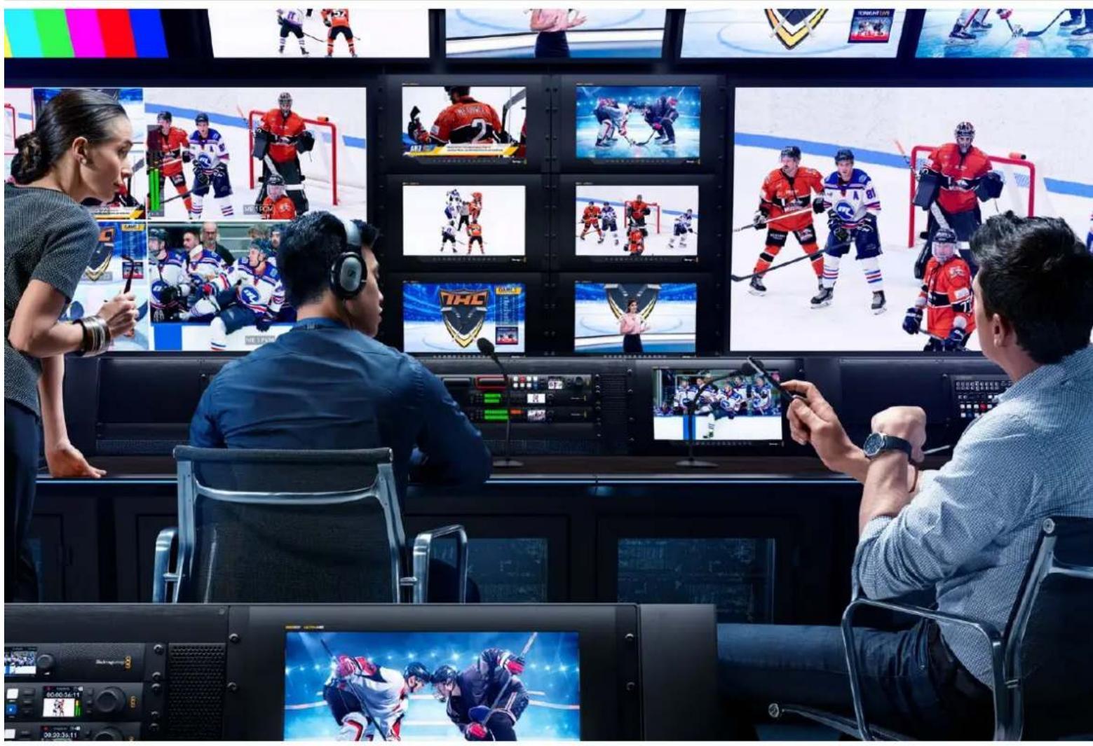

Bienvenue
Case Enable tally override 110
UtiliserSmartScopeDuo4K 110
Vertical Timing Reference 125
Blackmagic 2K Format - Data
Stream Format 125
Blackmagic SMARTView
Ethernet Protocol v1.4 126
Assistance 130
Avertissements 131
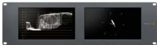
SmartView Duo SmartScope Duo 4K
Connector des sources video
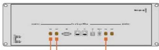
SmartView Duo SmartScope Duo 4K

InstallSmartView 5.0

Uninstall SmartView
Blackmagicdesign

MAC Address (Adresse MAC)
Réglages 2110 Receiver
Routez des sources entrantes versVoteSmartView 4KG3 via lesreglages 2110 receiver.
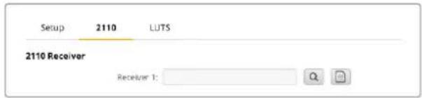
Announce Interval and Timeout
Case Enable tally override
Blackmagic Design products support 3G-SDI video, which allows twice the data rate of traditional HD-SDI video. We thought it would be a really nice idea to add 2K film support, via 3G-SDI technology, so we could simplify feature film workflows. With the popularity of Blackmagic Design editing systems worldwide, now thousands of people can benefit from a feature film workflow revolution.
This information includes everything product developers need to know for building native 2K SDI equipment. Of course, all Blackmagic products can be updated, so if the television industry adopts an alternative SDI-based film standard, we can add support for that too!
Frame Structure
- Transmitted at 23.98, 24 or 25 frames per second as a Progressive Segmented Frame.
Active video is 2048 pixels wide by 1556 lines deep.
Total lines per frame : 1650 - Active words per line are 1535. One word consists of a 10-bit sample for each of the four data streams, i.e., a total of 40 bits. See the diagram named Blackmagic 2K Format - Data Stream Format.
Total active lines: 1556
Total words per line: 1875 for 23.98/24Hz and 1800 for 25Hz.
Fields per frame: 2, 825 lines each
Active lines located on lines 16-793 (field 1) and 841-1618 (field 2).
Transport Structure
- Based on SMPTE 372M Dual Link mapping and SMPTE 425M-B support for mapping SMPTE 372M into a single 3 Gb/s link.
- Timing reference signals, line number and line CRC insertion is the same as above.
- During active video, 10-bit Red, Green and Blue data is sent in the following sequence:
- Optional ancillary data is inserted into both virtual interfaces.
-
At present, only audio data is included: as per standard HD audio insertion (SMPTE S299M) the audio data packets are carried on data stream two and audio control packets are carried on data stream one.
-
Data stream 1: Green_1, Green_2, Green_3, Green_5...Green_2047
- Data stream 2: Blue_1, Blue_2, Green_4, Blue_5...Green_2048.
- Data stream 3: Red_1, Blue_3, Blue_4, Red_5...Blue_2048.
Data stream 4: Red_2, Red_3, Red_4, Red_6...Red_2048.
Blackmagic 2K Format - Vertical Timing Reference
This diagram shows the vertical timing details with line numbers and Field, Vertical and Horizontal bits for the Timing Reference Signal codes.
| Field 1 Active | ||||||||||||
| F1000 | 0000 | 000 | ||||||||||
| V11111 | 0000 | 11 | ||||||||||
| LINE # | 1650 | 1 | 2 | ... | 14 | 15 | 16 | ... | 792 | 793 | ... | 825 |
| Field 2 Active | ||||||||||||
| F | 0 | 1 | 1 | 1 | 1 | 1 | 1 | 1 | 1 | 1 | 1 | 1 |
| V | 1 | 1 | 1 | 1 | 1 | 1 | 0 | 0 | 0 | 0 | 1 | 1 |
| LINE # | 825 | 826 | 827 | ... | 839 | 840 | 841 | ... | 1617 | 1618 | ... | 1650 |
Blackmagic 2K Format - Data Stream Format
This diagram shows the data stream formats around the optional ancillary data section of the horizontal line. Note that each active pixel takes up three samples.
| Word#25 PsF | Word#23.98/24 PsF | Data Stream 4 | Data Stream 3 | Data Stream 2 | Data Stream 1 |
| 1795 | 1870 | R2042 | R2041 | B2041 | G2041 |
| 1796 | 1871 | R2043 | B2043 | B2042 | G2042 |
| 1797 | 1872 | R2044 | B2044 | G2044 | G2043 |
| 1798 | 1873 | R2046 | R2045 | B2045 | G2045 |
| 1799 | 1874 | R2047 | B2047 | B2046 | G2046 |
| 1800 | 1875 | R2048 | B2048 | G2048 | G2047 |
| 1 | 1 | EAV(3FFh) | EAV(3FFh) | EAV(3FFh) | EAV(3FFh) |
| 2 | 2 | EAV(000h) | EAV(000h) | EAV(000h) | EAV(000h) |
| 3 | 3 | EAV(000h) | EAV(000h) | EAV(000h) | EAV(000h) |
| 4 | 4 | EAV(XYZh) | EAV(XYZh) | EAV(XYZh) | EAV(XYZh) |
| 5 | 5 | LNO | LNO | LNO | LNO |
| 6 | 6 | LN1 | LN1 | LN1 | LN1 |
| 7 | 7 | CRCO | CRCO | CRCO | CRCO |
| 8 | 8 | CRC1 | CRC1 | CRC1 | CRC1 |
| 9 | 9 | 200 | 040 | ANC/Audio Data | ANC/Audio Data |
| ... | ... | ... | ... | ||
| 260 | 335 | 200 | 040 | ||
| 261 | 336 | SAV(3FFh) | SAV(3FFh) | SAV(3FFh) | SAV(3FFh) |
| 262 | 337 | SAV(000h) | SAV(000h) | SAV(000h) | SAV(000h) |
| 263 | 338 | SAV(000h) | SAV(000h) | SAV(000h) | SAV(000h) |
| 264 | 339 | SAV(XYZh) | SAV(XYZh) | SAV(XYZh) | SAV(XYZh) |
| 265 | 340 | R2 | R1 | B1 | G1 |
| 266 | 341 | R3 | B3 | B2 | G2 |
| 267 | 342 | R4 | B4 | G4 | G3 |
| 268 | 343 | R6 | R5 | B5 | G5 |
Blackmagic SmartView Ethernet Protocol v1.4
Summary
The Blackmagic SmartView Ethernet Protocol is a text-based status and control protocol, very similar in structure to the Videohub protocol, that is accessed by connecting to TCP port 9992 on a SmartView or SmartScope monitor.
Upon connection, the SmartView or SmartScope monitor sends a complete dump of the state of the monitor. After the initial dump, state changes are sent asynchronously.
The SmartView or SmartScope sends information in blocks which have an identifying header, followed by a colon. A block can span multiple lines and is terminated by a blank line.
To be resilient to future protocol changes, clients should ignore blocks they do not recognize, up to the trailing blank line. Within recognized blocks, clients should ignore lines they do not recognize.
Legend
carriage return
and so on
Version 1.4 of the Blackmagic SmartView Ethernet
Protocol was released with SmartView 1.4 software.
Protocol Preamble
The first block sent by the SmartView Server is always the protocol preamble:
PROTOCOL PREAMBLE:
Version: 1.4
The version field indicates the protocol version. When the protocol is changed in a compatible way, the minor version number will be updated. If incompatible changes are made, the major version number will be updated.
Device Information
The next block contains general information about the connected SmartView or SmartScope.
SMARTVIEW DEVICE:←
Model:SmartView Duo
Hostname: stagefront studio.example.com
Name:StageFront
Monitors: 2
Inverted: false
This example shows the output for a SmartView Duo, which has two LCDs.
The INVERTED flag indicates whether the monitor has detected that it has been mounted in an inverted configuration to optimize LCD viewing angle.
Network Configuration
The next block shows the TCP/IP networking configuration:
NETWORK:
Dynamic IP: true
Static address: 192.168.2.0
Static n etm ask: 255.255.255.0
St atic g atew ay: 192.168.241
C u r rent add r ess: 192.168.1-101
C u r rent n etm ask: 255.255.255.0
C u r rent gate w ay: 192.168.4.1
The network settings prefixed with CURRENT show the active TCP/IP settings, and are readily. The CURRENT settings reflect either the DHCP or Static configuration, depending on the DYNAMIC IP flag.
Changing Networking Settings
The network can be configured to use either DHCP or a static configuration. To enable DHCP:
NETWORK:
Dynamic IP: true
←
To set a fixed IP address, supply all static parameters, thus:
NETWORK:
Dynamic IP: false
Static address: 192.168.2.2
Static netm ask: 255.255.255.0
St atic g atew ay: 192.168.2.1
The parameters with the CURRENT prefix are read-only, and show the active configuration, regardless of the static or dynamic setting.
Changing the name, or any network settings, will cause the IP connection to be dropped. The SmartView or SmartScope will restart its networking and advertise its new name on the network.
Changing Monitor Settings
The display settings for each monitor are specified individually. One or more parameters can be modified at the same time and multiple settings can be supplied in one block.
The valid range for numeric values is 0-255. The CONTRAST and SATURATION properties are zero-centered, so the normal value is 127, such that the displayed picture is the same as the original. A value greater than 127 in either channel will cause the contrast or saturation to be increased, and similarly a value less than 127 will cause a decrease.
For example, to set the brightness to 50% and desaturate the image to Black & White:
MONITOR A: Brightness: 127 Saturation: 0
Displaying SD in 16:9
The following command sets standard definition video to display in 16:9:
MONITOR A:
WidescreenSD:ON
Displaying SD in 4:3
The following command sets standard definition video to display in 4:3:
MONITOR A:
WidescreenSD: OFF
Identification and Tally Settings
The Identify flag is transient, and will cause a white border to be displayed around the entire picture for a duration of 15 seconds, after which it will be reset. This feature is primarily aimed at identifying which monitor is currently being configured when it is mounted in a rack comprising multiple units. To turn on:
MONITOR A:
Identify: trale
The IDENTIFY border will temporarily override any other border setting in effect.
The BORDER property can be used to programmatically set the soft Tally colored borders to one of the primary colors: RED, GREEN, BLUE, WHITE or NONE. This setting can be overridden by the electrical Tally signals at the DB-9 input on the monitor itself. For example, to set the soft Tally to green:
MONITOR B:
Border:green
The hard wired tally will always override the soft tally. The full state report will always show the current valid border.
SmartScope Settings
On SmartScope Duo 4K, each monitor can be set to display a different scope. The values for activating specific scopes are mapped as follows:
AudioDbfs
AudioDbvu
Histogram
ParadeRGB
ParadeYUV
Picture (This is the same as Video Monitor)
Vector100
Vector75
WaveformLuma
MONITOR A:
ScopeMode: Picture
In the example above, Monitor A has been set as a video monitor.
Displaying SD in 16:9
The set Video Monitor mode to display standard definition video in 16:9:
MOTOR A:ScopeMode:Picture WidescreenSD:ON
Displaying SD in 4:3
To set Video Monitor mode to display standard definition video in 4:3:
MOTOR A:ScopeMode:Picture WidescreenSD:OFF
When setting one of SmartScope Duo 4K's monitors to audio metering, you can also select which channels to show. The values for selecting which audio channels are mapped in the following way:
0: Channels 1 and 2
1: Channels 3 and 4
2: Channels 5 and 6
3: Channels 7 and 8
4: Channels 9 and 10
5: Channels 11 and 12
6: Channels 13 and 14
7: Channels 15 and 16
MONITOR B:ScopeMode:AudioDbvu AudioChannel:0
In the example above, Monitor B has been selected to display Audio Metering in Dbvu with audio channels 1 and 2 selected for the phase meter.
Selecting LUTs for SmartView 4K
To select 3D LUTs using SmartView 4K:
MONITOR A: LUT: 0 LUT 1 LUT 2 NONE DISABLE
Assistance
-3G-SDI:PL-4F20-311C
-6G-SDI:PL-8F10-311C
-12G-SDI:PL-TG10-311C

SmartView & SmartScope


Willkommen!
CEO, Blackmagic Design
Inhaltsverzeichnis
Erste Schritte 137
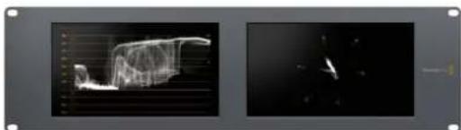
SmartView Duo SmartScope Duo 4K
"Allow Utility Administration"
"Announce Interval" und "Announce Timeout"
Blackmagic Design products support 3G-SDI video, which allows twice the data rate of traditional HD-SDI video. We thought it would be a really nice idea to add 2K film support, via 3G-SDI technology, so we could simplify feature film workflows. With the popularity of Blackmagic Design editing systems worldwide, now thousands of people can benefit from a feature film workflow revolution.
This information includes everything product developers need to know for building native 2K SDI equipment. Of course, all Blackmagic products can be updated, so if the television industry adopts an alternative SDI-based film standard, we can add support for that too!
Frame Structure
- Transmitted at 23.98, 24 or 25 frames per second as a Progressive Segmented Frame.
Active video is 2048 pixels wide by 1556 lines deep.
Total lines per frame : 1650 - Active words per line are 1535. One word consists of a 10-bit sample for each of the four data streams, i.e., a total of 40 bits. See the diagram named Blackmagic 2K Format - Data Stream Format.
Total active lines: 1556
Total words per line: 1875 for 23.98/24Hz and 1800 for 25Hz.
Fields per frame: 2, 825 lines each
Active lines located on lines 16-793 (field 1) and 841-1618 (field 2).
Transport Structure
- Based on SMPTE 372M Dual Link mapping and SMPTE 425M-B support for mapping SMPTE 372M into a single 3 Gb/s link.
- Timing reference signals, line number and line CRC insertion is the same as above.
- During active video, 10-bit Red, Green and Blue data is sent in the following sequence:
- Optional ancillary data is inserted into both virtual interfaces.
-
At present, only audio data is included: as per standard HD audio insertion (SMPTE S299M) the audio data packets are carried on data stream two and audio control packets are carried on data stream one.
-
Data stream 1: Green_1, Green_2, Green_3, Green_5...Green_2047
- Data stream 2: Blue_1, Blue_2, Green_4, Blue_5...Green_2048.
- Data stream 3: Red_1, Blue_3, Blue_4, Red_5...Blue_2048.
Data stream 4: Red_2, Red_3, Red_4, Red_6...Red_2048.
Blackmagic 2K Format - Vertical Timing Reference
This diagram shows the vertical timing details with line numbers and Field, Vertical and Horizontal bits for the Timing Reference Signal codes.
| Field 1 Active | ||||||||||||
| F1000 | 0000 | 000 | ||||||||||
| V11111 | 0000 | 11 | ||||||||||
| LINE # | 1650 | 1 | 2 | ... | 14 | 15 | 16 | ... | 792 | 793 | ... | 825 |
| Field 2 Active | ||||||||||||
| F | 0 | 1 | 1 | 1 | 1 | 1 | 1 | 1 | 1 | 1 | 1 | 1 |
| V | 1 | 1 | 1 | 1 | 1 | 1 | 0 | 0 | 0 | 0 | 1 | 1 |
| LINE # | 825 | 826 | 827 | ... | 839 | 840 | 841 | ... | 1617 | 1618 | ... | 1650 |
Blackmagic 2K Format - Data Stream Format
This diagram shows the data stream formats around the optional ancillary data section of the horizontal line. Note that each active pixel takes up three samples.
| Word#25 PsF | Word#23.98/24 PsF | Data Stream 4 | Data Stream 3 | Data Stream 2 | Data Stream 1 |
| 1795 | 1870 | R2042 | R2041 | B2041 | G2041 |
| 1796 | 1871 | R2043 | B2043 | B2042 | G2042 |
| 1797 | 1872 | R2044 | B2044 | G2044 | G2043 |
| 1798 | 1873 | R2046 | R2045 | B2045 | G2045 |
| 1799 | 1874 | R2047 | B2047 | B2046 | G2046 |
| 1800 | 1875 | R2048 | B2048 | G2048 | G2047 |
| 1 | 1 | EAV(3FFh) | EAV(3FFh) | EAV(3FFh) | EAV(3FFh) |
| 2 | 2 | EAV(000h) | EAV(000h) | EAV(000h) | EAV(000h) |
| 3 | 3 | EAV(000h) | EAV(000h) | EAV(000h) | EAV(000h) |
| 4 | 4 | EAV(XYZh) | EAV(XYZh) | EAV(XYZh) | EAV(XYZh) |
| 5 | 5 | LNO | LNO | LNO | LNO |
| 6 | 6 | LN1 | LN1 | LN1 | LN1 |
| 7 | 7 | CRCO | CRCO | CRCO | CRCO |
| 8 | 8 | CRC1 | CRC1 | CRC1 | CRC1 |
| 9 | 9 | 200 | 040 | ANC/Audio Data | ANC/Audio Data |
| ... | ... | ... | ... | ||
| 260 | 335 | 200 | 040 | ||
| 261 | 336 | SAV(3FFh) | SAV(3FFh) | SAV(3FFh) | SAV(3FFh) |
| 262 | 337 | SAV(000h) | SAV(000h) | SAV(000h) | SAV(000h) |
| 263 | 338 | SAV(000h) | SAV(000h) | SAV(000h) | SAV(000h) |
| 264 | 339 | SAV(XYZh) | SAV(XYZh) | SAV(XYZh) | SAV(XYZh) |
| 265 | 340 | R2 | R1 | B1 | G1 |
| 266 | 341 | R3 | B3 | B2 | G2 |
| 267 | 342 | R4 | B4 | G4 | G3 |
| 268 | 343 | R6 | R5 | B5 | G5 |
Blackmagic SmartView Ethernet Protocol v1.4
Summary
The Blackmagic SmartView Ethernet Protocol is a text-based status and control protocol, very similar in structure to the Videohub protocol, that is accessed by connecting to TCP port 9992 on a SmartView or SmartScope monitor.
Upon connection, the SmartView or SmartScope monitor sends a complete dump of the state of the monitor. After the initial dump, state changes are sent asynchronously.
The SmartView or SmartScope sends information in blocks which have an identifying header, followed by a colon. A block can span multiple lines and is terminated by a blank line.
To be resilient to future protocol changes, clients should ignore blocks they do not recognize, up to the trailing blank line. Within recognized blocks, clients should ignore lines they do not recognize.
Legend
carriage return ... and so on
Version 1.4 of the Blackmagic SmartView Ethernet Protocol was released with SmartView 1.4 software.
Protocol Preamble
The first block sent by the SmartView Server is always the protocol preamble:
PROTOCOL PREAMBLE: Version: 1.4
The version field indicates the protocol version. When the protocol is changed in a compatible way, the minor version number will be updated. If incompatible changes are made, the major version number will be updated.
Device Information
The next block contains general information about the connected SmartView or SmartScope.
SMARTVIEW DEVICE:
Model: SmartView Duo
Hostname: stagefront studio.example.com
Name: StageFront
Monitors: 2
Inverted: false
This example shows the output for a SmartView Duo, which has two LCDs.
The INVERTED flag indicates whether the monitor has detected that it has been mounted in an inverted configuration to optimize LCD viewing angle.
Network Configuration
The next block shows the TCP/IP networking configuration:
NETWORK:
Dynamic IP: true
Static address: 192.168.2.2
Static n etm ask: 255.255.255.0
St atic g atew ay: 192.168.241
C u r rent add r ess: 192.168.1.101
C u r rent n etm ask: 255.255.265.0
C u r rent gate w ay: 192.168.1.1
The network settings prefixed with CURRENT show the active TCP/IP settings, and are readily. The CURRENT settings reflect either the DHCP or Static configuration, depending on the DYNAMIC IP flag.
Changing Networking Settings
The network can be configured to use either DHCP or a static configuration. To enable DHCP:
NETWORK:
Dynamic IP: true
←
To set a fixed IP address, supply all static parameters, thus:
NETWORK:
Dynamic IP: false
Static address: 192.168.2.2
Static n etm ask: 255.255.255.e1
St atic g atew ay: 192.168.241
The parameters with the CURRENT prefix are read-only, and show the active configuration, regardless of the static or dynamic setting.
Changing the name, or any network settings, will cause the IP connection to be dropped. The SmartView or SmartScope will restart its networking and advertise its new name on the network.
Changing Monitor Settings
The display settings for each monitor are specified individually. One or more parameters can be modified at the same time and multiple settings can be supplied in one block.
The valid range for numeric values is 0-255. The CONTRAST and SATURATION properties are zero-centered, so the normal value is 127, such that the displayed picture is the same as the original. A value greater than 127 in either channel will cause the contrast or saturation to be increased, and similarly a value less than 127 will cause a decrease.
For example, to set the brightness to 50% and desaturate the image to Black & White:
MONITOR A: Brightness: 127 Saturation: 0
Displaying SD in 16:9
The following command sets standard definition video to display in 16:9:
MONITOR A:
WidescreenSD:ON
Displaying SD in 4:3
The following command sets standard definition video to display in 4:3:
MONITOR A:
WidescreenSD: OFF
Identification and Tally Settings
The Identify flag is transient, and will cause a white border to be displayed around the entire picture for a duration of 15 seconds, after which it will be reset. This feature is primarily aimed at identifying which monitor is currently being configured when it is mounted in a rack comprising multiple units. To turn on:
MONITOR A:
Identify: trade
The IDENTIFY border will temporarily override any other border setting in effect.
The BORDER property can be used to programmatically set the soft Tally colored borders to one of the primary colors: RED, GREEN, BLUE, WHITE or NONE. This setting can be overridden by the electrical Tally signals at the DB-9 input on the monitor itself. For example, to set the soft Tally to green:
MONITOR B:
Border:green
The hard wired tally will always override the soft tally. The full state report will always show the current valid border.
SmartScope Settings
On SmartScope Duo 4K, each monitor can be set to display a different scope. The values for activating specific scopes are mapped as follows:
AudioDbfs
AudioDbvu
Histogram
ParadeRGB
ParadeYUV
Picture (This is the same as Video Monitor)
Vector100
Vector75
WaveformLuma
MONITOR A:
ScopeMode: Picture
In the example above, Monitor A has been set as a video monitor.
Displaying SD in 16:9
The set Video Monitor mode to display standard definition video in 16:9:
MOTOR A:ScopeMode:Picture WidescreenSD:ON
Displaying SD in 4:3
To set Video Monitor mode to display standard definition video in 4:3:
MOTOR A:ScopeMode:Picture WidescreenSD:OFF
When setting one of SmartScope Duo 4K's monitors to audio metering, you can also select which channels to show. The values for selecting which audio channels are mapped in the following way:
0: Channels 1 and 2
1: Channels 3 and 4
2: Channels 5 and 6
3: Channels 7 and 8
4: Channels 9 and 10
5: Channels 11 and 12
6: Channels 13 and 14
7: Channels 15 and 16
MONITOR B:ScopeMode:AudioDbvu AudioChannel:0
In the example above, Monitor B has been selected to display Audio Metering in Dbvu with audio channels 1 and 2 selected for the phase meter.
Selecting LUTs for SmartView 4K
To select 3D LUTs using SmartView 4K:
MONITOR A: LUT: 0 LUT 1 1 LUT 2 NONE DISABLE
Hilfe
-3G-SDI:PL-4F20-311C
-6G-SDI:PL-8F10-311C
-12G-SDI:PL-TG10-311C

California Proposition 65
SmartView SmartScope


Bienvenido
Director executivo de Blackmagic Design
Índice
Primeros pasos 181
SmartView y SmartScope 181
Blackmagic SmartView
Ethernet Protocol v1.4 214
Ayuda 218
Normativas 219
Seguridad 220
Garantía 221
Primeros pasos
SmartView y SmartScope
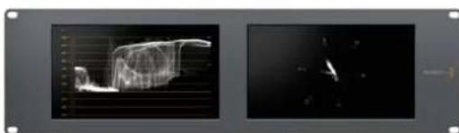
SmartView Duo SmartScope Duo 4K
Conexión de fuentes
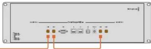
SmartView Duo SmartScope Duo 4K

InstallSmartView 5.0

Uninstall SmartView
Blackmagicdesig

Blackmagic Design products support 3G-SDI video, which allows twice the data rate of traditional HD-SDI video. We thought it would be a really nice idea to add 2K film support, via 3G-SDI technology, so we could simplify feature film workflows. With the popularity of Blackmagic Design editing systems worldwide, now thousands of people can benefit from a feature film workflow revolution.
This information includes everything product developers need to know for building native 2K SDI equipment. Of course, all Blackmagic products can be updated, so if the television industry adopts an alternative SDI-based film standard, we can add support for that too!
Frame Structure
- Transmitted at 23.98, 24 or 25 frames per second as a Progressive Segmented Frame.
Active video is 2048 pixels wide by 1556 lines deep.
Total lines per frame : 1650 - Active words per line are 1535. One word consists of a 10-bit sample for each of the four data streams, i.e., a total of 40 bits. See the diagram named Blackmagic 2K Format - Data Stream Format.
Total active lines: 1556
Total words per line: 1875 for 23.98/24Hz and 1800 for 25Hz.
Fields per frame: 2, 825 lines each
Active lines located on lines 16-793 (field 1) and 841-1618 (field 2).
Transport Structure
- Based on SMPTE 372M Dual Link mapping and SMPTE 425M-B support for mapping SMPTE 372M into a single 3 Gb/s link.
- Timing reference signals, line number and line CRC insertion is the same as above.
- During active video, 10-bit Red, Green and Blue data is sent in the following sequence:
- Optional ancillary data is inserted into both virtual interfaces.
-
At present, only audio data is included: as per standard HD audio insertion (SMPTE S299M) the audio data packets are carried on data stream two and audio control packets are carried on data stream one.
-
Data stream 1: Green_1, Green_2, Green_3, Green_5...Green_2047
- Data stream 2: Blue_1, Blue_2, Green_4, Blue_5...Green_2048.
- Data stream 3: Red_1, Blue_3, Blue_4, Red_5...Blue_2048.
Data stream 4: Red_2, Red_3, Red_4, Red_6...Red_2048.
Blackmagic 2K Format - Vertical Timing Reference
This diagram shows the vertical timing details with line numbers and Field, Vertical and Horizontal bits for the Timing Reference Signal codes.
| Field 1 Active | ||||||||||||
| F1000 | 0000 | 000 | ||||||||||
| V11111 | 0000 | 11 | ||||||||||
| LINE # | 1650 | 1 | 2 | ... | 14 | 15 | 16 | ... | 792 | 793 | ... | 825 |
| Field 2 Active | ||||||||||||
| F | 0 | 1 | 1 | 1 | 1 | 1 | 1 | 1 | 1 | 1 | 1 | 1 |
| V | 1 | 1 | 1 | 1 | 1 | 1 | 0 | 0 | 0 | 0 | 1 | 1 |
| LINE # | 825 | 826 | 827 | ... | 839 | 840 | 841 | ... | 1617 | 1618 | ... | 1650 |
Blackmagic 2K Format - Data Stream Format
This diagram shows the data stream formats around the optional ancillary data section of the horizontal line. Note that each active pixel takes up three samples.
| Word#25 PsF | Word#23.98/24 PsF | Data Stream 4 | Data Stream 3 | Data Stream 2 | Data Stream 1 |
| 1795 | 1870 | R2042 | R2041 | B2041 | G2041 |
| 1796 | 1871 | R2043 | B2043 | B2042 | G2042 |
| 1797 | 1872 | R2044 | B2044 | G2044 | G2043 |
| 1798 | 1873 | R2046 | R2045 | B2045 | G2045 |
| 1799 | 1874 | R2047 | B2047 | B2046 | G2046 |
| 1800 | 1875 | R2048 | B2048 | G2048 | G2047 |
| 1 | 1 | EAV(3FFh) | EAV(3FFh) | EAV(3FFh) | EAV(3FFh) |
| 2 | 2 | EAV(000h) | EAV(000h) | EAV(000h) | EAV(000h) |
| 3 | 3 | EAV(000h) | EAV(000h) | EAV(000h) | EAV(000h) |
| 4 | 4 | EAV(XYZh) | EAV(XYZh) | EAV(XYZh) | EAV(XYZh) |
| 5 | 5 | LNO | LNO | LNO | LNO |
| 6 | 6 | LN1 | LN1 | LN1 | LN1 |
| 7 | 7 | CRCO | CRCO | CRCO | CRCO |
| 8 | 8 | CRC1 | CRC1 | CRC1 | CRC1 |
| 9 | 9 | 200 | 040 | ANC/Audio Data | ANC/Audio Data |
| ... | ... | ... | ... | ||
| 260 | 335 | 200 | 040 | ||
| 261 | 336 | SAV(3FFh) | SAV(3FFh) | SAV(3FFh) | SAV(3FFh) |
| 262 | 337 | SAV(000h) | SAV(000h) | SAV(000h) | SAV(000h) |
| 263 | 338 | SAV(000h) | SAV(000h) | SAV(000h) | SAV(000h) |
| 264 | 339 | SAV(XYZh) | SAV(XYZh) | SAV(XYZh) | SAV(XYZh) |
| 265 | 340 | R2 | R1 | B1 | G1 |
| 266 | 341 | R3 | B3 | B2 | G2 |
| 267 | 342 | R4 | B4 | G4 | G3 |
| 268 | 343 | R6 | R5 | B5 | G5 |
Blackmagic SmartView Ethernet Protocol v1.4
Summary
The Blackmagic SmartView Ethernet Protocol is a text-based status and control protocol, very similar in structure to the Videohub protocol, that is accessed by connecting to TCP port 9992 on a SmartView or SmartScope monitor.
Upon connection, the SmartView or SmartScope monitor sends a complete dump of the state of the monitor. After the initial dump, state changes are sent asynchronously.
The SmartView or SmartScope sends information in blocks which have an identifying header, followed by a colon. A block can span multiple lines and is terminated by a blank line.
To be resilient to future protocol changes, clients should ignore blocks they do not recognize, up to the trailing blank line. Within recognized blocks, clients should ignore lines they do not recognize.
Legend
carriage return
and so on
Version 1.4 of the Blackmagic SmartView Ethernet Protocol was released with SmartView 1.4 software.
Protocol Preamble
The first block sent by the SmartView Server is always the protocol preamble:
PROTOCOL PREAMBLE: Version: 1.4
The version field indicates the protocol version. When the protocol is changed in a compatible way, the minor version number will be updated. If incompatible changes are made, the major version number will be updated.
Device Information
The next block contains general information about the connected SmartView or SmartScope.
SMARTVIEW DEVICE:
Model: SmartView Duo
Hostname: stagefront studio.example.com
Name: StageFront
Monitors: 2
Inverted: false
This example shows the output for a SmartView Duo, which has two LCDs.
The INVERTED flag indicates whether the monitor has detected that it has been mounted in an inverted configuration to optimize LCD viewing angle.
Network Configuration
The next block shows the TCP/IP networking configuration:
NETWORK:
Dynamic IP: true
Static address: 192.168.2.0
Static n etm ask: 255.255.255.0
St atic g atew ay: 192.168.241
C u r rent add r ess: 192.168.1-101
C u r rent n etm ask: 255.255.255.0
C u r rent gate w ay: 192.168.4.1
The network settings prefixed with CURRENT show the active TCP/IP settings, and are readily. The CURRENT settings reflect either the DHCP or Static configuration, depending on the DYNAMIC IP flag.
Changing Networking Settings
The network can be configured to use either DHCP or a static configuration. To enable DHCP:
NETWORK:
Dynamic IP: true
←
To set a fixed IP address, supply all static parameters, thus:
NETWORK:
Dynamic IP: false
Static address: 192.168.2.2
Static n etm ask: 255.255.255.e1
St atic g atew ay: 192.168.241
The parameters with the CURRENT prefix are read-only, and show the active configuration, regardless of the static or dynamic setting.
Changing the name, or any network settings, will cause the IP connection to be dropped. The SmartView or SmartScope will restart its networking and advertise its new name on the network.
Changing Monitor Settings
The display settings for each monitor are specified individually. One or more parameters can be modified at the same time and multiple settings can be supplied in one block.
The valid range for numeric values is 0-255. The CONTRAST and SATURATION properties are zero-centered, so the normal value is 127, such that the displayed picture is the same as the original. A value greater than 127 in either channel will cause the contrast or saturation to be increased, and similarly a value less than 127 will cause a decrease.
For example, to set the brightness to 50% and desaturate the image to Black & White:
MONITOR A: Brightness: 127 Saturation: 0
Displaying SD in 16:9
The following command sets standard definition video to display in 16:9:
MONITOR A:
WidescreenSD:ON
Displaying SD in 4:3
The following command sets standard definition video to display in 4:3:
MONITOR A:
WidescreenSD: OFF
Identification and Tally Settings
The Identify flag is transient, and will cause a white border to be displayed around the entire picture for a duration of 15 seconds, after which it will be reset. This feature is primarily aimed at identifying which monitor is currently being configured when it is mounted in a rack comprising multiple units. To turn on:
MONITOR A:
Identify: trade
The IDENTIFY border will temporarily override any other border setting in effect.
The BORDER property can be used to programmatically set the soft Tally colored borders to one of the primary colors: RED, GREEN, BLUE, WHITE or NONE. This setting can be overridden by the electrical Tally signals at the DB-9 input on the monitor itself. For example, to set the soft Tally to green:
MONITOR B:
Border:green
The hard wired tally will always override the soft tally. The full state report will always show the current valid border.
SmartScope Settings
On SmartScope Duo 4K, each monitor can be set to display a different scope. The values for activating specific scopes are mapped as follows:
AudioDbfs
AudioDbvu
Histogram
ParadeRGB
ParadeYUV
Picture (This is the same as Video Monitor)
Vector100
Vector75
WaveformLuma
MONITOR A:
ScopeMode: Picture
In the example above, Monitor A has been set as a video monitor.
Displaying SD in 16:9
The set Video Monitor mode to display standard definition video in 16:9:
MOTOR A:ScopeMode:Picture WidescreenSD:ON
Displaying SD in 4:3
To set Video Monitor mode to display standard definition video in 4:3:
MOTOR A:ScopeMode:Picture WidescreenSD:OFF
When setting one of SmartScope Duo 4K's monitors to audio metering, you can also select which channels to show. The values for selecting which audio channels are mapped in the following way:
0: Channels 1 and 2
1: Channels 3 and 4
2: Channels 5 and 6
3: Channels 7 and 8
4: Channels 9 and 10
5: Channels 11 and 12
6: Channels 13 and 14
7: Channels 15 and 16
MONITOR B:ScopeMode:AudioDbvu AudioChannel:0
In the example above, Monitor B has been selected to display Audio Metering in Dbvu with audio channels 1 and 2 selected for the phase meter.
Selecting LUTs for SmartView 4K
To select 3D LUTs using SmartView 4K:
MONITOR A: LUT: 0 LUT 1 1 LUT 2 NONE DISABLE
Ayuda
Cómo Obtener ahora
SmartView SmartScope


致用户
Blackmagic SmartView
Ethernet Protocol v1.4 258
帮助 262
监管声明 263
安全信息 264
保修 265
开始使用
SmartView和SmartScope产品简介
SmartView和SmartScope Duo 4K
Blackmagic Design products support 3G-SDI video, which allows twice the data rate of traditional HD-SDI video. We thought it would be a really nice idea to add 2K film support, via 3G-SDI technology, so we could simplify feature film workflows. With the popularity of Blackmagic Design editing systems worldwide, now thousands of people can benefit from a feature film workflow revolution.
This information includes everything product developers need to know for building native 2K SDI equipment. Of course, all Blackmagic products can be updated, so if the television industry adopts an alternative SDI-based film standard, we can add support for that too!
Frame Structure
- Transmitted at 23.98, 24 or 25 frames per second as a Progressive Segmented Frame.
Active video is 2048 pixels wide by 1556 lines deep.
Total lines per frame : 1650 - Active words per line are 1535. One word consists of a 10-bit sample for each of the four data streams, i.e., a total of 40 bits. See the diagram named Blackmagic 2K Format - Data Stream Format.
Total active lines: 1556
Total words per line: 1875 for 23.98/24Hz and 1800 for 25Hz.
Fields per frame: 2, 825 lines each
Active lines located on lines 16-793 (field 1) and 841-1618 (field 2).
Transport Structure
- Based on SMPTE 372M Dual Link mapping and SMPTE 425M-B support for mapping SMPTE 372M into a single 3 Gb/s link.
- Timing reference signals, line number and line CRC insertion is the same as above.
- During active video, 10-bit Red, Green and Blue data is sent in the following sequence:
- Optional ancillary data is inserted into both virtual interfaces.
- At present, only audio data is included: as per standard HD audio insertion (SMPTE S299M) the audio data packets are carried on data stream two and audio control packets are carried on data stream one.
Data stream 1: Green_1, Green_2, Green_3, Green_5...Green_2047
Data stream 2: Blue_1, Blue_2, Green_4, Blue_5...Green_2048.
- Data stream 3: Red_1, Blue_3, Blue_4, Red_5...Blue_2048.
Data stream 4: Red_2, Red_3, Red_4, Red_6...Red_2048.
Blackmagic 2K Format - Vertical Timing Reference
This diagram shows the vertical timing details with line numbers and Field, Vertical and Horizontal bits for the Timing Reference Signal codes.
| Field 1 Active | ||||||||||||
| F1000 | 0000 | 000 | ||||||||||
| V11111 | 0000 | 11 | ||||||||||
| LINE # | 1650 | 1 | 2 | ... | 14 | 15 | 16 | ... | 792 | 793 | ... | 825 |
| Field 2 Active | ||||||||||||
| F | 0 | 1 | 1 | 1 | 1 | 1 | 1 | 1 | 1 | 1 | 1 | 1 |
| V | 1 | 1 | 1 | 1 | 1 | 1 | 0 | 0 | 0 | 0 | 1 | 1 |
| LINE # | 825 | 826 | 827 | ... | 839 | 840 | 841 | ... | 1617 | 1618 | ... | 1650 |
Blackmagic 2K Format - Data Stream Format
This diagram shows the data stream formats around the optional ancillary data section of the horizontal line. Note that each active pixel takes up three samples.
| Word#25 PsF | Word#23.98/24 PsF | Data Stream 4 | Data Stream 3 | Data Stream 2 | Data Stream 1 |
| 1795 | 1870 | R2042 | R2041 | B2041 | G2041 |
| 1796 | 1871 | R2043 | B2043 | B2042 | G2042 |
| 1797 | 1872 | R2044 | B2044 | G2044 | G2043 |
| 1798 | 1873 | R2046 | R2045 | B2045 | G2045 |
| 1799 | 1874 | R2047 | B2047 | B2046 | G2046 |
| 1800 | 1875 | R2048 | B2048 | G2048 | G2047 |
| 1 | 1 | EAV(3FFh) | EAV(3FFh) | EAV(3FFh) | EAV(3FFh) |
| 2 | 2 | EAV(000h) | EAV(000h) | EAV(000h) | EAV(000h) |
| 3 | 3 | EAV(000h) | EAV(000h) | EAV(000h) | EAV(000h) |
| 4 | 4 | EAV(XYZh) | EAV(XYZh) | EAV(XYZh) | EAV(XYZh) |
| 5 | 5 | LNO | LNO | LNO | LNO |
| 6 | 6 | LN1 | LN1 | LN1 | LN1 |
| 7 | 7 | CRCO | CRCO | CRCO | CRCO |
| 8 | 8 | CRC1 | CRC1 | CRC1 | CRC1 |
| 9 | 9 | 200 | 040 | ANC/Audio Data | ANC/Audio Data |
| ... | ... | ... | ... | ||
| 260 | 335 | 200 | 040 | ||
| 261 | 336 | SAV(3FFh) | SAV(3FFh) | SAV(3FFh) | SAV(3FFh) |
| 262 | 337 | SAV(000h) | SAV(000h) | SAV(000h) | SAV(000h) |
| 263 | 338 | SAV(000h) | SAV(000h) | SAV(000h) | SAV(000h) |
| 264 | 339 | SAV(XYZh) | SAV(XYZh) | SAV(XYZh) | SAV(XYZh) |
| 265 | 340 | R2 | R1 | B1 | G1 |
| 266 | 341 | R3 | B3 | B2 | G2 |
| 267 | 342 | R4 | B4 | G4 | G3 |
| 268 | 343 | R6 | R5 | B5 | G5 |
Blackmagic SmartView Ethernet Protocol v1.4
Summary
The Blackmagic SmartView Ethernet Protocol is a text-based status and control protocol, very similar in structure to the Videohub protocol, that is accessed by connecting to TCP port 9992 on a SmartView or SmartScope monitor.
Upon connection, the SmartView or SmartScope monitor sends a complete dump of the state of the monitor. After the initial dump, state changes are sent asynchronously.
The SmartView or SmartScope sends information in blocks which have an identifying header, followed by a colon. A block can span multiple lines and is terminated by a blank line.
To be resilient to future protocol changes, clients should ignore blocks they do not recognize, up to the trailing blank line. Within recognized blocks, clients should ignore lines they do not recognize.
Legend
carriage return ... and so on
Version 1.4 of the Blackmagic SmartView Ethernet Protocol was released with SmartView 1.4 software.
Protocol Preamble
The first block sent by the SmartView Server is always the protocol preamble:
PROTOCOL PREAMBLE: Version: 1.4
The version field indicates the protocol version. When the protocol is changed in a compatible way, the minor version number will be updated. If incompatible changes are made, the major version number will be updated.
Device Information
The next block contains general information about the connected SmartView or SmartScope.
SMARTVIEW DEVICE:
Model: SmartView Duo
Hostname: stagefront studio.example.com
Name: StageFront
Monitor s: 2
Inverted: false
This example shows the output for a SmartView Duo, which has two LCDs.
The INVERTED flag indicates whether the monitor has detected that it has been mounted in an inverted configuration to optimize LCD viewing angle.
Network Configuration
The next block shows the TCP/IP networking configuration:
NETWORK:
Dynamic IP: true
Static address: 192.168.2.2
Static n etm ask: 255.255.255.0
St atic g atew ay: 192.168.241
C u r rent add r e s s: 192.168.14101
C u r rent n etm ask: 255.255.265.0
C u r rent gate w ay: 192.168.4.1
The network settings prefixed with CURRENT show the active TCP/IP settings, and are readily. The CURRENT settings reflect either the DHCP or Static configuration, depending on the DYNAMIC IP flag.
Changing Networking Settings
The network can be configured to use either DHCP or a static configuration. To enable DHCP:
NETWORK:
Dynamic IP: true
←
To set a fixed IP address, supply all static parameters, thus:
NETWORK:
Dynamic IP: false
Static address: 192.168.2.2
Static netm ask: 255.255.255.0
St atic g atew ay: 192.168.241
The parameters with the CURRENT prefix are read-only, and show the active configuration, regardless of the static or dynamic setting.
Changing the name, or any network settings, will cause the IP connection to be dropped. The SmartView or SmartScope will restart its networking and advertise its new name on the network.
Changing Monitor Settings
The display settings for each monitor are specified individually. One or more parameters can be modified at the same time and multiple settings can be supplied in one block.
The valid range for numeric values is 0-255. The CONTRAST and SATURATION properties are zero-centered, so the normal value is 127, such that the displayed picture is the same as the original. A value greater than 127 in either channel will cause the contrast or saturation to be increased, and similarly a value less than 127 will cause a decrease.
For example, to set the brightness to 50% and desaturate the image to Black & White:
MONITOR A: Brightness: 127 Saturation: 0
Displaying SD in 16:9
The following command sets standard definition video to display in 16:9:
MONITOR A:
WidescreenSD:ON
Displaying SD in 4:3
The following command sets standard definition video to display in 4:3:
MONITOR A:
WidescreenSD: OFF
Identification and Tally Settings
The Identify flag is transient, and will cause a white border to be displayed around the entire picture for a duration of 15 seconds, after which it will be reset. This feature is primarily aimed at identifying which monitor is currently being configured when it is mounted in a rack comprising multiple units. To turn on:
MONITOR A:
Identify: trade
The IDENTIFY border will temporarily override any other border setting in effect.
The BORDER property can be used to programmatically set the soft Tally colored borders to one of the primary colors: RED, GREEN, BLUE, WHITE or NONE. This setting can be overridden by the electrical Tally signals at the DB-9 input on the monitor itself. For example, to set the soft Tally to green:
MONITOR B:
Border:green
The hard wired tally will always override the soft tally. The full state report will always show the current valid border.
SmartScope Settings
On SmartScope Duo 4K, each monitor can be set to display a different scope. The values for activating specific scopes are mapped as follows:
AudioDbfs
AudioDbvu
Histogram
ParadeRGB
ParadeYUV
Picture (This is the same as Video Monitor)
Vector100
Vector75
WaveformLuma
MONITOR A:
ScopeMode: Picture
In the example above, Monitor A has been set as a video monitor.
Displaying SD in 16:9
The set Video Monitor mode to display standard definition video in 16:9:
MOTOR A:ScopeMode:Picture WidescreenSD:ON
Displaying SD in 4:3
To set Video Monitor mode to display standard definition video in 4:3:
MOTOR A:ScopeMode:Picture WidescreenSD:OFF
When setting one of SmartScope Duo 4K's monitors to audio metering, you can also select which channels to show. The values for selecting which audio channels are mapped in the following way:
0: Channels 1 and 2
1: Channels 3 and 4
2: Channels 5 and 6
3: Channels 7 and 8
4: Channels 9 and 10
5: Channels 11 and 12
6: Channels 13 and 14
7: Channels 15 and 16
MONITOR B:ScopeMode:AudioDbvu AudioChannel:0
In the example above, Monitor B has been selected to display Audio Metering in Dbvu with audio channels 1 and 2 selected for the phase meter.
Selecting LUTs for SmartView 4K
To select 3D LUTs using SmartView 4K:
MONITOR A: LUT: 0 LUT 1 1 LUT 2 NONE DISABLE
帮助
获得帮助
获得帮助的渠道有以下四种:
12G-SDI:PL-TG10-311C

请在海拔高度2000米以下的地区使用。
加利福尼亚安全声明
SmartView SmartScope


宣
NettoTweK3Wtck(Network Location)
NeteTwoKwHcNtNnKsNaTaNnSmartView4KG3IiOpnNi.1n 1
MAC status(MAC Address)
iEeH 4K G3 MAC
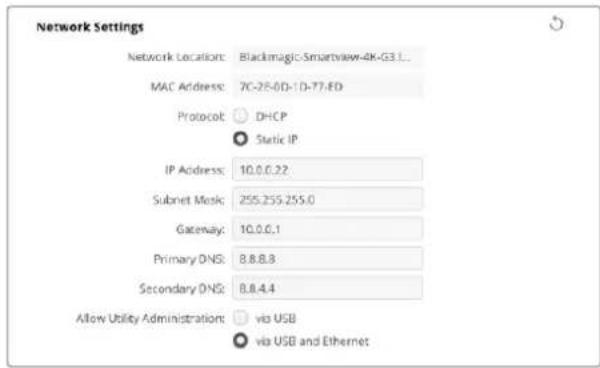
Protocol
| DHCP | SmartView 4K G3 MyNiTBeN is DHCP for gerbment of houh. |
| DHCP(Dynamic Host Configuration Protocol) is the way to use a unique and common name in a server. | |
| HCP is an entity that can be used to establish a connection between a server and another server. | |
| HCP is an entity that can be used to establish a connection between a server and another server. | |
| Static IP (Static IP) is the set of IP addresses that are assigned to a specific server. |
```c 実例10.10 ```c 適用範圍 = All ``` 適用範圍 = Allow Utility Administration)
MAsTeJtEeTbEeTAEeTbEeTbEeTbEeTbEeTbEeTbEeTbEeTbEeTbEeTbEeTbEeTbEeTbEeTbEeTbEeTbEeTbEeTbEeTbEeTbEeTbEeTbEeTbEeTbEeTbEeTbEsTeBcTeBcTeBcTeBcTeBcTeBcTeBcTeBcTeBcTeBcTeBcTeBcTeBcTeBcTeBcTeBcTeBcTeBcTeBcTeBcTeBcTeBcTeBcTeBcTeBcTeBcTeBcTeBcTeBcTeBcTeBcTeBcTeBcTeBc
PTP加密(PTP Lock)
'PTP Lock' 1
★
SmartView 4K G3が 'PTP flalrowl 凉用(PTP follower only)'urof selctedor iniJt Jnge, PTP MaStToR sUHah SuHsuHJtJrUsuHJtJrUsuHJtJrUsuHJtJrUsuHJtJrUsuHJtJrUsuHJtJrUsuHJtJrUsuHJtJrUsuHJtJrUsuHJtJrUsuHJtJrUsuHJtJrUsuHJtJrUsuHJtJrUsuH
Announce interval & Announce Timeout)
announce interval) und Announce Interval) und Announce Timeout) firdn n 2000ms)
da dng h e s t i t to 1000m
NMOS Rerits (NMOS Registry)
NMOS ReteisStreIiIPuSnsusundouuHryHnAuto'chInanLtoeikhhyNtTwK3NMOsL 1
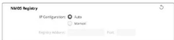
LUT
SmartView和SmartScope Duo 4K
KAPALRA SDI HOLERySMarView Duo 4K of SmartScope Due 4K of the A/BB ene hae
ATEM S-WI-CHIeFIOE 10000000000000000000000000000000000000000000000
SmartScope Duo 4K 썸용해
Blackmagic SmartScope !
NeTwJcKStWJtHEneTJrJcKoMnDKeTjTeAeTgTtJcKoMeNtJcKoMeNtJcKoMeNtJcKoMeNtJcKoMeNtJcKoMeNtJcKoMeNtJcKoMeNtJcKoMeNtJcKoMeNtJcKoMeNtJcKoMeNtJcKoMeNtJcKoMeNtJcKoMeNt
Blackmagic Design products support 3G-SDI video, which allows twice the data rate of traditional HD-SDI video. We thought it would be a really nice idea to add 2K film support, via 3G-SDI technology, so we could simplify feature film workflows. With the popularity of Blackmagic Design editing systems worldwide, now thousands of people can benefit from a feature film workflow revolution.
This information includes everything product developers need to know for building native 2K SDI equipment. Of course, all Blackmagic products can be updated, so if the television industry adopts an alternative SDI-based film standard, we can add support for that too!
Frame Structure
- Transmitted at 23.98, 24 or 25 frames per second as a Progressive Segmented Frame.
Active video is 2048 pixels wide by 1556 lines deep.
Total lines per frame:1650 - Active words per line are 1535. One word consists of a 10-bit sample for each of the four data streams, i.e., a total of 40 bits. See the diagram named Blackmagic 2K Format - Data Stream Format.
Total active lines: 1556
Total words per line: 1875 for 23.98/24Hz and 1800 for 25Hz.
Fields per frame: 2, 825 lines each
Active lines located on lines 16-793 (field 1) and 841-1618 (field 2).
Transport Structure
- Based on SMPTE 372M Dual Link mapping and SMPTE 425M-B support for mapping SMPTE 372M into a single 3 Gb/s link.
- Timing reference signals, line number and line CRC insertion is the same as above.
- During active video, 10-bit Red, Green and Blue data is sent in the following sequence:
- Optional ancillary data is inserted into both virtual interfaces.
- At present, only audio data is included: as per standard HD audio insertion (SMPTE S299M) the audio data packets are carried on data stream two and audio control packets are carried on data stream one.
Data stream 1: Green_1, Green_2, Green_3, Green_5...Green_2047
- Data stream 2: Blue_1, Blue_2, Green_4, Blue_5...Green_2048.
- Data stream 3: Red_1, Blue_3, Blue_4, Red_5...Blue_2048.
Data stream 4: Red_2, Red_3, Red_4, Red_6...Red_2048.
Blackmagic 2K Format - Vertical Timing Reference
This diagram shows the vertical timing details with line numbers and Field, Vertical and Horizontal bits for the Timing Reference Signal codes.
| Field 1 Active | ||||||||||||
| F1000 | 0000 | 000 | ||||||||||
| V1111 | 0000 | 11 | ||||||||||
| LINE # | 1650 | 1 | 2 | ... | 14 | 15 | 16 | ... | 792 | 793 | ... | 825 |
| Field 2 Active | ||||||||||||
| F | 0 | 1 | 1 | 1 | 1 | 1 | 1 | 1 | 1 | 1 | 1 | 1 |
| V | 1 | 1 | 1 | 1 | 1 | 1 | 0 | 0 | 0 | 0 | 1 | 1 |
| LINE # | 825 | 826 | 827 | ... | 839 | 840 | 841 | ... | 1617 | 1618 | ... | 1650 |
Blackmagic 2K Format - Data Stream Format
This diagram shows the data stream formats around the optional ancillary data section of the horizontal line. Note that each active pixel takes up three samples.
| Word#25 PsF | Word#23.98/24 PsF | Data Stream 4 | Data Stream 3 | Data Stream 2 | Data Stream 1 |
| 1795 | 1870 | R2042 | R2041 | B2041 | G2041 |
| 1796 | 1871 | R2043 | B2043 | B2042 | G2042 |
| 1797 | 1872 | R2044 | B2044 | G2044 | G2043 |
| 1798 | 1873 | R2046 | R2045 | B2045 | G2045 |
| 1799 | 1874 | R2047 | B2047 | B2046 | G2046 |
| 1800 | 1875 | R2048 | B2048 | G2048 | G2047 |
| 1 | 1 | EAV(3FFh) | EAV(3FFh) | EAV(3FFh) | EAV(3FFh) |
| 2 | 2 | EAV(000h) | EAV(000h) | EAV(000h) | EAV(000h) |
| 3 | 3 | EAV(000h) | EAV(000h) | EAV(000h) | EAV(000h) |
| 4 | 4 | EAV(XYZh) | EAV(XYZh) | EAV(XYZh) | EAV(XYZh) |
| 5 | 5 | LNO | LNO | LNO | LNO |
| 6 | 6 | LN1 | LN1 | LN1 | LN1 |
| 7 | 7 | CRCO | CRCO | CRCO | CRCO |
| 8 | 8 | CRC1 | CRC1 | CRC1 | CRC1 |
| 9 | 9 | 200 | 040 | ANC/Audio Data | ANC/Audio Data |
| ... | ... | ... | ... | ||
| 260 | 335 | 200 | 040 | ||
| 261 | 336 | SAV(3FFh) | SAV(3FFh) | SAV(3FFh) | SAV(3FFh) |
| 262 | 337 | SAV(000h) | SAV(000h) | SAV(000h) | SAV(000h) |
| 263 | 338 | SAV(000h) | SAV(000h) | SAV(000h) | SAV(000h) |
| 264 | 339 | SAV(XYZh) | SAV(XYZh) | SAV(XYZh) | SAV(XYZh) |
| 265 | 340 | R2 | R1 | B1 | G1 |
| 266 | 341 | R3 | B3 | B2 | G2 |
| 267 | 342 | R4 | B4 | G4 | G3 |
| 268 | 343 | R6 | R5 | B5 | G5 |
Blackmagic SmartView Ethernet Protocol v1.4
Summary
The Blackmagic SmartView Ethernet Protocol is a text-based status and control protocol, very similar in structure to the Videohub protocol, that is accessed by connecting to TCP port 9992 on a SmartView or SmartScope monitor.
Upon connection, the SmartView or SmartScope monitor sends a complete dump of the state of the monitor. After the initial dump, state changes are sent asynchronously.
The SmartView or SmartScope sends information in blocks which have an identifying header, followed by a colon. A block can span multiple lines and is terminated by a blank line.
To be resilient to future protocol changes, clients should ignore blocks they do not recognize, up to the trailing blank line. Within recognized blocks, clients should ignore lines they do not recognize.
Legend
carriage return
and so on
Version 1.4 of the Blackmagic SmartView Ethernet
Protocol was released with SmartView 1.4 software.
Protocol Preamble
The first block sent by the SmartView Server is always the protocol preamble:
PROTOCOL PREAMBLE:
Version: 1.4
The version field indicates the protocol version. When the protocol is changed in a compatible way, the minor version number will be updated. If incompatible changes are made, the major version number will be updated.
Device Information
The next block contains general information about the connected SmartView or SmartScope.
SMARTVIEW DEVICE:
Model:SmartView Duo
Hostname: stagefront studio.example.com
Name:StageFront
Monitors: 2
Inverted: false
This example shows the output for a SmartView Duo, which has two LCDs.
The INVERTED flag indicates whether the monitor has detected that it has been mounted in an inverted configuration to optimize LCD viewing angle.
Network Configuration
The next block shows the TCP/IP networking configuration:
NETWORK:
Dynamic IP: true
Static address: 192.168.2.2
Static n etm ask: 255.255.255.0
St atic g atew ay: 192.168.241
C u r rent add r e s s: 192.168.14101
C u r rent n etm ask: 255.255.265.0
C u r rent gate w ay: 192.168.4.1
The network settings prefixed with CURRENT show the active TCP/IP settings, and are readily. The CURRENT settings reflect either the DHCP or Static configuration, depending on the DYNAMIC IP flag.
Changing Networking Settings
The network can be configured to use either DHCP or a static configuration. To enable DHCP:
NETWORK:
Dynamic IP: true
←
To set a fixed IP address, supply all static parameters, thus:
NETWORK:
Dynamic IP: false
Static address: 192.168.2.2
Static netm ask: 255.255.255.0
St atic g atew ay: 192.168.241
The parameters with the CURRENT prefix are read-only, and show the active configuration, regardless of the static or dynamic setting.
Changing the name, or any network settings, will cause the IP connection to be dropped. The SmartView or SmartScope will restart its networking and advertise its new name on the network.
Changing Monitor Settings
The display settings for each monitor are specified individually. One or more parameters can be modified at the same time and multiple settings can be supplied in one block.
The valid range for numeric values is 0-255. The CONTRAST and SATURATION properties are zero-centered, so the normal value is 127, such that the displayed picture is the same as the original. A value greater than 127 in either channel will cause the contrast or saturation to be increased, and similarly a value less than 127 will cause a decrease.
For example, to set the brightness to 50% and desaturate the image to Black & White:
MONITOR A: Brightness: 127 Saturation: 0
Displaying SD in 16:9
The following command sets standard definition video to display in 16:9:
MONITOR A:
WidescreenSD:ON
Displaying SD in 4:3
The following command sets standard definition video to display in 4:3:
MONITOR A:
WidescreenSD: OFF
Identification and Tally Settings
The Identify flag is transient, and will cause a white border to be displayed around the entire picture for a duration of 15 seconds, after which it will be reset. This feature is primarily aimed at identifying which monitor is currently being configured when it is mounted in a rack comprising multiple units. To turn on:
MONITOR A:
Identify: trade
The IDENTIFY border will temporarily override any other border setting in effect.
The BORDER property can be used to programmatically set the soft Tally colored borders to one of the primary colors: RED, GREEN, BLUE, WHITE or NONE. This setting can be overridden by the electrical Tally signals at the DB-9 input on the monitor itself. For example, to set the soft Tally to green:
MONITOR B:
Border:green
The hard wired tally will always override the soft tally. The full state report will always show the current valid border.
SmartScope Settings
On SmartScope Duo 4K, each monitor can be set to display a different scope. The values for activating specific scopes are mapped as follows:
AudioDbfs
AudioDbvu
Histogram
ParadeRGB
ParadeYUV
Picture (This is the same as Video Monitor)
Vector100
Vector75
WaveformLuma
MONITOR A:
ScopeMode: Picture
In the example above, Monitor A has been set as a video monitor.
Displaying SD in 16:9
The set Video Monitor mode to display standard definition video in 16:9:
MOTOR A:ScopeMode:Picture WidescreenSD:ON
Displaying SD in 4:3
To set Video Monitor mode to display standard definition video in 4:3:
MOTOR A:ScopeMode:Picture WidescreenSD:OFF
When setting one of SmartScope Duo 4K's monitors to audio metering, you can also select which channels to show. The values for selecting which audio channels are mapped in the following way:
0: Channels 1 and 2
1: Channels 3 and 4
2: Channels 5 and 6
3: Channels 7 and 8
4: Channels 9 and 10
5: Channels 11 and 12
6: Channels 13 and 14
7: Channels 15 and 16
MONITOR B:ScopeMode:AudioDbvu AudioChannel:0
In the example above, Monitor B has been selected to display Audio Metering in Dbvu with audio channels 1 and 2 selected for the phase meter.
Selecting LUTs for SmartView 4K
To select 3D LUTs using SmartView 4K:
MONITOR A: LUT: 0 LUT 1 1 LUT 2 NONE DISABLE
日
지원발기
歌云日,
Knag Blackmagic Design SFP 0
-3G-SDI:PL-4F20-311C
-6G-SDI:PL-8F10-311C
-12G-SDI:PL-TG10-311C
2000m
策拉托尼阿孕
SmartView SmartScope


YBaKaembl Nolb3OBaTeIb!
MblcTpeMMcK TOMy, yTo6bI TeNEBnDEHne CTano ObnaCTbIO HAcToaIeTO TBOpueCTBa, rDe IIO60I IMeET BO3MOXHOCTb CO3DaBaTa MATEpNAI CAMO RBCOKORo yPOBH.
Длг STORO Heo6xOIMO KOHTpOINPOBAtb KaueCTBO CnHana. MoIeNB SmartView 4K G3 nmeet KK-ducnnie 15,6 duimOB c pa3pewaioe cnocobnoctb 4K,чTo no3BOJraT OTcIeXuBaTB n3o6paKeHne B Ultra HD,a Kopnyc 6 RU c naHeIbU npaBHeHna DaET BO3MOXHOCTb 6bICTpo MeHrTa HAcTPOKn.YSmartScpe Duo 4K ecT bDa He3aBncMbIX 8-DIOIMOBbIX ekpaHa N MOHtOpINrФopMb cInHana dI pyunipOBKn erO npaMeTpOB BHe cTuDn. BlaRaOapra HauNHy INTEPpeiCa 3G-SDI BCa liNeiKa SmartView obecneuBaET BbIOd MaTePnAa B SD, HD n 2K, a yCTpoiCTBa SmartScpe Duo 4K n SmartView 4K G3 - eIe n B Ultra HD uepez pa3bEmbl 6G-SDI n 12G-SDI coOTBeTCTBeHHo.KpOme TOrO, Ha SmartView 4K G3 npeycmotpeHa noidepxkka IP-BuJeO SMPTE 2110 n KoDeKa Blackmagic IP10.
MOnHTOpbI NO3BOJIAOT KOHTpOINPOBAt bKaueCTBO CnHana, a yTInNtA Blackmagic SmartView Setup nmeet npocTo n INHTyNTBHO NOHrTHbI Ha6Op INHCTpyMeHToB.
3To pykoBCTBO COePjNT BCIO INHΦOpMaIIO, Heo6xOaMMyIO IЯ pa60Tb C MOHITOPAMN SmartView n SmartScope. EIn BBy He 3Haete, KaK 3aAaTB IP-aDpec N cTeBbIe npaMeTpbl, Lyuwe BCero o6paTtbcra 3a NOMObIIO K TexHnueckOMy CneuaJIcTcy. IcNoIb3OBAHne yCtpoiCTBa He Tpe6yeT Oco6bIX HABbIKOB, Ondako B Haayane Heo6xOaIMo BbINONHHTb ONpeJeHHyIO HAcTpoiKy.
Ipouecc yctahOBKn 3aHnMaet np6blnteNbHO pTb MInHy. TTo6bl 3arpy3ntb nocneHIOBepcnIO pykoBOcTBa I nporpaMMHOro npiloxHn, nocTe NTpe pa3dien noDepkKn HaHaawem caIte No aDpccy www.blackmagicdesign.com/ru. Ppi 3arpy3ke PO He 3abydtE3aperncptnpobatbcra dna nonyuHnco6uHn O BbInycke oupeHoro peN3a.MbI NOCTOHHo pa60Taem HAd COBepseHCTBOBaHnem HaWix npOdyKTOB, N0TOMy BaWn OT3bIBbI NOMOT Ham cdeNaTb nx eue lyUwe.

Ppant Nettn
TenepaBbHbI dIpeKTop KOMnAHn Blackmagic Design
CopepxaHne
IpoTroBka K pa6ote 313
0630p MoHToPoB SmartView
nSmartScope 313
IopKnIOUeHne IcToHnKOB BnJeO 314
IopKJIIOUeHne K KOMnIbIoTepy 315
Pabota c ytnlntoi Blackmagic
SmartView Setup 316
UctaHOBka yTnInbI Blackmagic
SmartView Setup 316
O6HOBJIeHHe nporpaMMHOro
06ecnehen 317
Pa6ota co SmartView 4K G3 318
KhoNn naHEn ynpaBneHn 319
Bndeokoek Blackmagic IP10 321
I3meHeHnHe Hactpoek
C NOMOJIyTNITbl Blackmagic
SmartView Setup 322
BknaKa HacpoKn 322
Bkla2 2110 325
BklaKa LUTS 327
SmartView n SmartScope Duo 4K 328
N3meHeHn Hacptpoek MoHITopa 328
HactpoKa Enable Tally Override 330
Pa6ota co SmartScope Duo 4K 330
O630p MoHtopa Blackmagic
SmartScope 330
Onuia Video Monitoring 331
Icnnei fopmbicnHa 332
Bektopockon 333
Диспел NapametpoB 334
Tnctorpamma 336
ypoBeHb 38yKa 337
CeteBbI npaMeTpbl 338
PoiKIOUeHnE K IokaIbHOcETn 339
IopKnIOueHne K cetn Ethernet 339
CeteBOn KOMMyTaTOp 340
Hdkaa coctoHH 341
KoHTaKTbI npTa Tally-HHdkaCun 341
PerynipoBka yrgna o63opa 342
Developer Information 344
Blackmagic 2K Format-Overview 344
Blackmagic 2K Format - Vertical Timing Reference 345
Blackmagic 2K Format - Data Stream Format 345
BlackmagicSmartView Ethernet Protocolv1.4 346
POMOu 350
CobJeHHe HOpMaTHBbIX Tpe6oBaHn 351
IpaBnna 6e3oNaChoctn 352
Tapaantna 353
Повтовka к paбote
0630p мониторов SmartView n SmartScope
MoHITOpbI SmartView nideaIbHO NOxOJAT Ipa3MeueHnB CToIke C o6OpyDobAHnEM. TTo6bI npCTyInbK paOte,IOCTaTOUHO BKNIOHTb NITAHne IN COeHNHTb YCTPOINCTBO C NCTOCHNKOM SDI-cuHaIa.
ModenbSmartView4K G3 imeet 4K-dncnnei dnaarohnbio 15,6 ioumOB, oecneuBaa BbOa SD-HD- nII Ultra HD-Bndeo B pa3peweHn 3840 x 2160. C nOmoBIO KHOKONK HA nepedne naHemMOxHO BbpaTB BXOD, HACPTOnB JRPKocTb EKpHa, IPOBepNTb Wym B CINHe M KaHale, IpOCMOTpeTb clyke6hble daHHbI e npimEnHt 3D LUT-tabniu.
ModelbSmartViewDuoIMeETDBAINCNIIeIINOHOBpeMeHHOROBbIOa pa3HbIXSD-NHDnToKOB.Hanpimep,oINMOXHOHCNOJIb3OBaTBJNYYUV4:2NNNTSC,a npyro- nraRGB4:4Ii60PAL.PrINBCEMMHOKeCTBeBapnaHTOBKBKaJdOMcIyueTepebyetcTobkoNDKluHTbSDI-KabeBkNCtOuHHkyI3OpaKeHH.
MoIeB SmartScope Duo 4K Imeet Takoi Je Habop yHKun, KaK SmartView Duo, Ho DOnoJIHInTeIbHO No3BOJnEe TB BIBOINtB φOpMy CnIHaIa, NcNoJIb3OBaTb BeKTopoCkON I pyrHe INdIkaTOPbI dIg MOHITOPINHra BnDeO n ayDIO B peaIbHOM BpemeHN. Kpome TOrO, OHa NOdepxKnBaET paOty c Ultra HD.
HInTepeicSDHaSmartViewuSmartScpeaTOMaTuueckn onpeJeAeT fOpMaT noctyaiooero BIneoOT SD uHD do 3G-SDI, B Tom uCne 2K. Moelb SmartView 4K G3 c noDepkko12G-SDI TaKke no3BoJraT paOToTaB c Ultra HD, BKnIOUaY 2160p/60, a SmartScope Duo 4K -c Ultra HD uepe3 6G-SDI.
Ha moeenn SmartView 4K G3 dOonHnTeBHo ecTb npT 10G 2110 IP npiema IP-Bndeo SMPTE 2110 Bnnotb do Ultra HD 2160p/60 npaBoTe c kOdekom Blackmagic IP10.
Длудаленногнгсгпн Heckobknx MoHntopOB SmartView nSmartScpe c odHoro KOMNbIOTepa donyckaetc nix noCneIOBATEbHOe noKNoUChene nO ceTn Ethernet. B 3tOM cnyae OTnadaET HeoXODIMOCTB BbINONHeHn TaKnx Opeaun B INDINBHyaNBHom nopAKe nyTeM coeINHeHry uepe3 npT USB.
Ioprotovka k pa6ote 3aBepseHa! PnDpObHee o noKIOUChEN MOHITOpOB SmartView nSmartScope, Hx HacTpoKe c nomoBko yTInlntbl Blackmagic SmartView Setup u coeINHeHN no cetu cm. pa3dEnb HnHex.

SmartView 4K G3
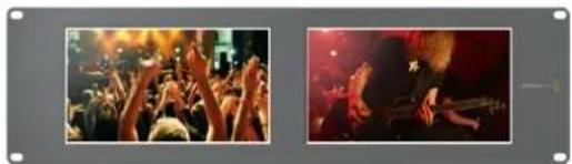
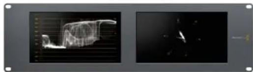
SmartView Duo SmartScope Duo 4K
IodKIOUeHne NCTOuHnKOB BnDeo
MoHITopbSmartView nSmartScpe ochaiaotcctaHdaptHBIMBNC-pa3beMaMn, KOTOpbIe oBeceuBaIOT COBmecTUMOCTb CtpaunIOHHBM SDI-OBOpyDobAHEm,B TOM uCne BInDeOMNKepaMn,KaMepaMn,IIaTaMn 3axBaTa,KeKaMn INCKOBbIMn peKOpdepaMn.
BbIOd n3OpaXeHnA
Дя Вьюда ИЗOBРALEДОТATOHNO NOДКПIOHTB ПИТAHNE I COEДНHTI NCTOCHK CINHANACSDI-BXODOM. ПОСLE ATORO OHO NOIPOBNTCR HA INCINPEE MOHITOPA. YCTPONCTBO ABTOMATUVECKN ONpeDJIETФОМAT BINOEO HA SDI-BXOeI cKBO3HOM INTEPΦeIe (SD, HD n 2K, a TAKKe Ultra HD npn pa6ote c moDEJAMN SmartView 4K G3 n SmartScope Duo 4K).
Pn OTCyTcBn NOCTynaIOUeO CnHaIa NODCBETKa MOHITOPa OTKIIIOuAeTcN IJI KHOHOMN 3NeKtpo3Heprnn.
TTo6bI npocmptpeb IP-Bndeo ST 2110 Ha moeenn SmartView 4K G3, nCnonb3yute dny noekluehern K cetn nopT 10G Ethernet nn doonHnTeNb h onntueckn SFP-mdynl.
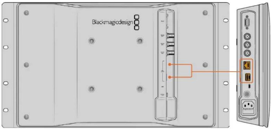
IocJeIOBaTeIbHoe coeINHeHne MOHTOpOB
ModenSmartView n SmartScpe mMeIeH3aBcMmbl SDI-BxOd nCKBO3HOBbIXoD,TO 03BOJnET BInONHHT bocneIOBaTeIbHOe NODKIOUeHHeNcKOJIbKnx MOHITOpOB dIy IpepaOn ODHOrO nTO rOg CINHana.
1 BknoHte nntaHne Ha yctpoiCTBe N° 1. CoeHHite uctouHK Bndeo c SDI-Bxodom. 306paXeHne 6ydt noctynatb Ha ekpaH.
2BkIIOHTe HtAHHe Ha yCTPOINCTBe N° 2.C IOMOUIo SDI-Ka6EJIra coeHNHte cKBO3HO BbIXoD yCTPOINCTBa N°1cSDI-BXODompeueHnN°2.
KoIuYeCTBO NOkJIIOUaEmbIX yCtpoiCTB He oPauHnueHO.
PnBbOeΦopMb CnHanaHa SmrScpe Duo 4K MoXHo CoeHNHTb BbIXoM OHITopa 1 c MOHITOPOM 2 nI npOBepKn OndHoro n toro Jne Notoka.
Bo Bpem npocmotpa n3o6paexHnI DOCTynHO n3MeHeHne HAcTpoek yCtpoiCTBa nnBbOp HnDnKaToPbIX dNarpam Ha SmartScpe Duo 4K c nomouy ytnntbl Blackmagic SmartView Setup, kotopaa takke no3Bolaret aarpykaTa 3D LUT-tabnUha Blackmagic SmartView 4KG3.
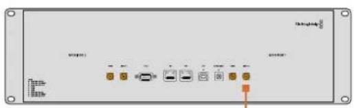
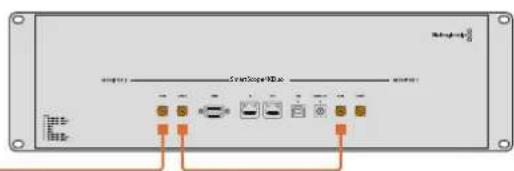
IopknoueHne K KomnbioTepy
Дянachtpoиь монтopa SmartView Ил SmartScope nodknoHTe erO K ПК сnomoцью USBAkeBЯ n yctahOBte ytnity Blackmagic SmartView Setup.
IopT USB takke cnkyknt dna obHOBneHn nporpaMMHoro oOecneHnra 3arpyKeHHoro cBe6caTAta KOMNaHN Blackmagic Design. YctahOBka nocneHne Bepcn IIO no3BOJnEePacwnpTa FyHKUHOHa, ynyuHTb COBmectUMoCTb C annapaTHbIMN ycToPcTBAMn N doBaNTb NOdApKky DonONHtJIbHbIX fOpMaTOB. Ytnlity Blackmagic SmartView Setup MOxHO nCNoB3OBA Tb Ha KOMNbIOTepax C onepaOnHHbIMn CInTeMAm Mac n Windows.
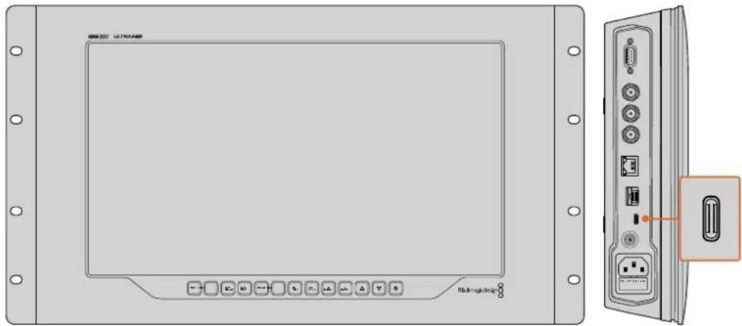
Popt USB-C pacnoonoxnHa 6okobon nobepxHocm MoHtopa SmartView 4K G3
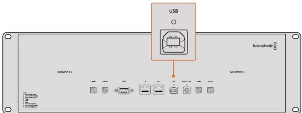
HaSmartViewDuo nopt USB haxoHCTc bHbOHTopHO
Раобота с ут annihilу Blackmagic SmartView Setup
YctaHOBka yTnIITbI Blackmagic SmartView Setup
Ytnta Blackmagic SmartView Setup coBmecnMa c nocneHmBepcmaOn npapaOnHoCnTeMb Mac, a TAKKe Windows 10 n 11 (64-pa3pHbHe Bepcn CakTyabHbIMn NaKetamnOboHbEnHa. Pn HeoXoDmOCn yctAHOBKa donyckaTc Ha HeckoIbKO ceTeBbIX KOMbIoTePOB.
HCTaTnTOp MoXHo 3aRpy3nTb no aDpecy www.blackmagicdesign.com/ru/support. Ero nCNoJIb3OBAHHe rapaHTnpyeY cTaHOBky nocneHHe Bepcnn.
PonjdoK yctahOBKn yTnInbI Blackmagic SmartView Setup
1Ipeennte no cbbInke
www.blackmagicdesign.com/ru/support/family/video-and-audio-monitoring nckaaynte noceHIOBercnOyTINbI Blackmagic SmartView.
2 Nocne okohuaHn 3arpy3Kn DbaKdbI ueKnHTe No 3Nauchy HnCTaJIaTopa dner ero 3anycka. Cnedynte nHcTpykunm Ha 3KpaHe n HaxMnte KhONky Install dner yctahOBKn PO.
3 Nocne yctahOBKn IIO nepeiDnte K nanke Blackmagic SmartView B cnncke npnloxeHnn nporpamM nDaBkDbl ueKHTe no 3Haay Ky tynlts SmartView Setup.
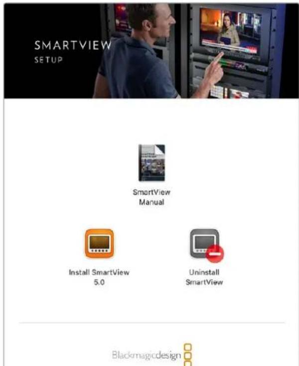
HaKomblbtepeMac3anyctne painSmartView.dmg n3nankn 3aRpyKeeHHbIX DOkymeHTOB,3aTeM DbaXdbI ZeIKKNTE NO 3HaKy INCTAANTopaa SmartView
OboBHeHne npoRpaMMHOro oBeCneueHn
Iocne 3aBepueHn yCTaHOBKn n 3anycky tynntbI Blackmagic SmartView Setup uenKhnte no 3Nauchky hactpoek noN HaZBaHHeM MOHTopa. Ecn nCNoNbayem Bepcny yCTapeNa, noBNTcra coo6eHne c npednoXeHnem oBHObntb IIO SmartView nIn SmartScope. dna 3toro BbINOHNte OINcaHHbIe Hnke deJeCTBn.
1 CoeHInHTe MoHITop SmartView mN SmartScpe c KOMbIOTepom Hepe3 npT USB nio Ethernet n 3anyCTte yTuNTy Blackmagic SmartView Setup.
2 Pn noBHeHn cooBcHn BbIepnte Update. PpoecC oBHOJIeHn 3aHMaet Okono Tn MNHyT.
Software Update
Update Available!
You can still use the SmartView 4K G3 if you don't update, but it may be missing the latest features.
Continue
Update
3 ПО okOHaHn OOBJIeHn NOBHTc coObIeHne "This SmartView has been updated".
4 Bbibepeute Close.
Ecnnncnno3yETcakTyaanbHaB Bepnra,OTKpoETcCTpaHnla C HactpouKaMm MOHTopa.
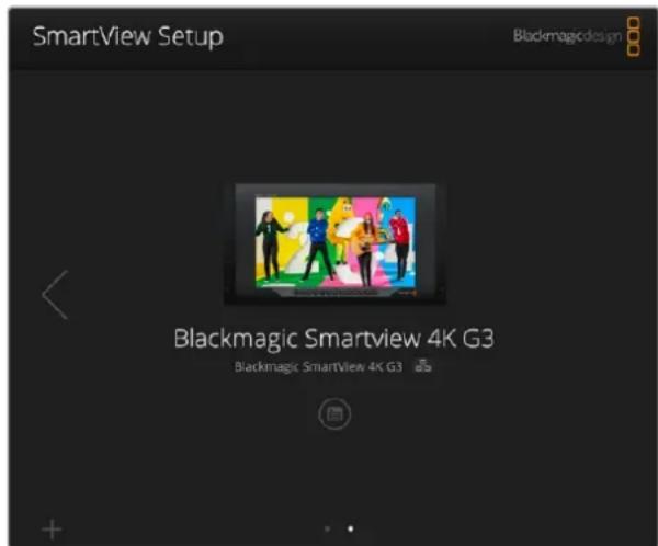
YtIuTa Blackmagic SmartView Setup abTomatueckn BbIOnHReT noNc yctpoCTB SmartView nSmartScope, noKlupeHHbIX no cTe nn nn cepe3 npT USB. Ecn nn Heckonko, nNoIb3yIte cTpeKN no 6okam NaalbHO CTpaHcUd Nn HabnuaM MeJdy HmN. ObHOJIra nporpAMMHO eObecneHHe, yBeintecb B hAnuH coedHHeHn C MOHTOpOM NO USB nn Ethernet.
Pa6ota co SmartView 4K G3
BeeataelbHmOHHTopSmartView4K G3 npn pa3mepe Kopnyca 6 RU nIMeet nHTeppeic 12G-SDI da pabo c Ultra HD. OH noDepknae TSD-, HD- n Ultra HD-foPmaTb BnIoTb do 2160p/60, a RPKn DnCnne C uPOKM yrnom o63opa oecneuBaet ToHyo fokycnpOBky mOHHTOpINr CBeta.
MoJebSmartView 4K G3 npedHa3haeHa Iry nCIOB3OBAHnB C tauHOapbIX MMOJIbHbIX CTyIaX. BOKOBoe paONoXeHne INTEpeFcOB N BO3MOXHOCTb KpenJeHnNo cTaNdApTy VESA NO3BOJAIOT BInONHtB yCTAHOBKY B yCNOBnX ORpaHueHHOro IpocTaPcHCTBa, Ha cTeHy nn NobopoTHbIKoHNHeh. MoHTop SmartView 4K G3 noDepknaeT dBa cnocoba ynpabLeHn: C NOMOsbBCTpoEHn NaHEnnn YdaNEHNO Yepe3 Ethernet npu OTCYrCTBn NOKaJIbHOrO DoCTya.
Два Вхда 12G-SDI no3BOLЯOT nCNoJIb3OBArBa pa3HBe IcTOnHnK SDI-cnHnAHa.ДонОнТeЛьНО npedymotpehI npR 2110 IP 10G Ethernet ДЯ NOdKnIOUeHnK KOMNbIoTePnoC cTeN,pa6To b C IP-BuJeO ST 2110 u nIcTaHnOHHOro ynpaBHeHn PIIoc rHeZdo NOD ONTuYeCKN SFP-MoDyB C NOdEprKoN 2110 IP u SDI.KpOme TOrO,ecTB pa3bEm DIA INHnKaun COCTOHRN BO BpEm EФир a HntepFeIC USB dIra nI3MeHnHn HAcTpoEk N O6HOBNeHn nporpaMMHoro obecneueHn C NOMOsbU yTNlNTb Blackmagic SmartView Setup.
Co3aHbE B npIIOxEHn DaVinci Resolve rpexmepHbe LUT-tabNcMoXHO 3arpy3ntb Ha SmartView 4K G3 ka Kaf bbl. cube, yTObB BBBOINb H3O6paXeHne C kAmepbHa MOHTOP B Tom BnDE, KOtOpB MaKcMamblNo npioLnxH K KOHeuHn Bercn Nocne rpeynHra. 3Ty oepauNO BbIOnHJOT c NOMoUbYyTInbbl Blackmagic SmartView Setup. Dba ypoBn BbIeJeHn KaHTypOB ObecneuBaHToUHyO fokycuPobkY, a COBMECTUMOCb C nCTOUYHKAMN NOCTOARHOrn I nepemehHoro TOKa No3BOJAE TNDKnIOUaTbcr K CETn EheprochaoXeHn N BHeUHemy AkkyMyIaTOpy Ha IIIOuaKe.
MoeBbSmartView 4K G3 RaIeTcra IeanbHbIM peWeHnEM dna MoHITOpINrBa CtynHbIX mObnbHbix yCIOBnX, oecneuBaB bIBoD He TOnbKO SD- n HD-, Ho n Ultra HD-BnDeo 3840 x 2160 nIKcenei.
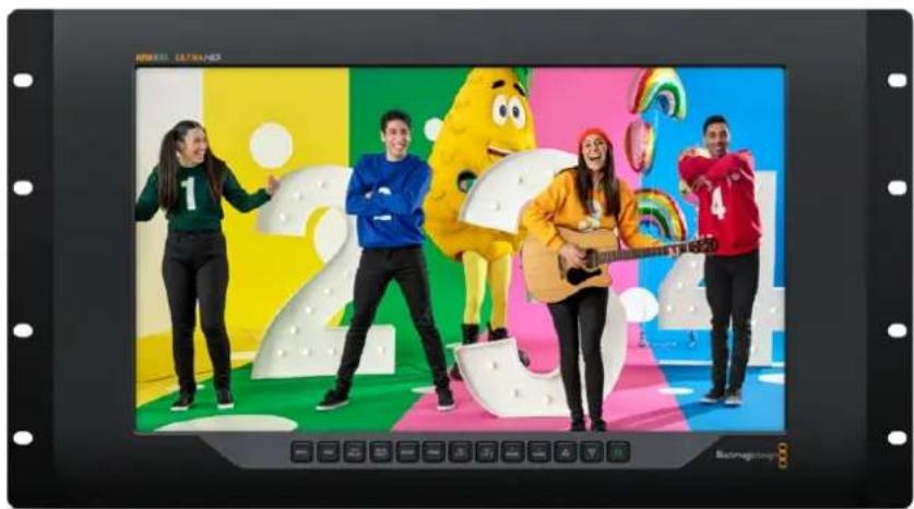
PIMMEAHNE. Pn noKIOHEnBHeHrO nCTouHka NtAHN Ko BXOy NOCToHHOrTo kya y6eINTEcB B TOM, 4TO BbIXoHn pa3bem aKKymIaTOpa paccHTaH MaOuHOCTb 24 BT npn HapJxKeHN 12 B.
KhoNk nHaHn ynpaBneHna
KhONKnHa naHenn ynpaBneHn cnykata 6bICTpO no3MeHn HAcTpoeK.
INPUT
3a KhoNka Cnyknt IyBb6opa N3O6paKeHnC OndHO rI DByx BxOoB 12G-SDI, paccbnaemoro no cetn IP-noToKa 2110 nnn cihrana, noctynaiooero uepez dononHntelbHy onTneckn SFPMoyn. EcnBnDeo OTCyTCTByET, kpaH MOHTopa SmartView 4K G3 6ydt cephim. Pnp nepeKnIOueHm Mekdy BxOaMn B BepxHem neBOM yRny KK-dncnner KpAkoBpeMeHNO BbBOHITcR INΦopMaun oΦopMaTe.
DISP
Cnyknt nna HactpoKn npKocTn KK-dncnner Ha MoHntope SmartView 4K G3 c nomoubIO ctpenok BBepx n BnI3. nBbIXoDa n3 HacToPkn HaxMnte KhONky eue pa3.
H/V DELAY
CnykntIgBbOdaDOnoHInTeBbIXDaHHbIX,BCTpoeHHbIX B SDI-BnEoo. YTo6bl yBnDeTB daHHbIe, paonoloxKeHHbIe rOpnoHTaJIbHO, HaxMnte KhoNky OdnH pa3. HaxMnte ee eue pa3 dnn oka3a BePTNKaJIbHbIX DaHHbIX, HanpIMep CkpbITbIX Cy6tNTPOB.
BLUE ONLY
IIO60IyM B CnHane UΦpOBO R BnDeo BoNbSe BCero 3aMeTeH B CnHem KaHaNE, NO3ToM yero MOHTOpHr IERKO BECTN C NOMOuBHO HaxaTIN COOTBeTCTByUOe N KHOKN. B NOIObHom cnyuae daHHBI KAHAJI OyET npedTcABHeN KAc YepHo-6eNoE N3OpaXeHne. OHO TAKKe MoKet cnykntb dIpyPObEPKn FOKUCIPOBKn KAMEpbI.
ZOOM
Cnyknt nna mmeHnna MacuTa6a n3o6paKeHn. YTo6bIyBENHT erO nnn npOBepKn
fOKcnpOBKn, nncnbl3yTe oDnHOKpaTHoe HaxaTne. DnBa Bo3Bpata K O6bUHOMy pa3Mepy HaxMNTe
KHONky eue pa3.
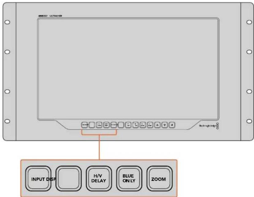
PEAK
CnykntIgnpOBepKn pokcnpBCK C nOmoBbBdeHnKoHTpyOB n3obpaXeHn. BOKpyr Hanboonepezknx 3neMeHOB 6ydt OTobpaXaTBCA 3eHnA KpOMKa. DnA 3ToN cyHKuIN npedyCMOTpeHb Dba yPobHn C nocJeDObaTeNbHbIM nepeKIOUeHnEM OT OHOH HAcTPOKN KdpYro. Korda 3eHnA KpOMKa Imeet HanBOonee OTcETNNBbBnBn, pOKyc KaMepbl HAcTPOEH TOHO.
3D LUT1n 3D LUT2
Cnykata NnBbOda n3o6paKeHn C npimeHeHm HnDnBnuyAaHBx 3D LUT-tabn, co3aHHbx B DaVinci Resolve (paih c pacupeHm .cube). DnB KIOUeHn IcNoIb3yIte OndokpatHoe Haxatne. Ttob otKIOHHTb LUT-tabn, hXKMITE KHOKNy eue pa3. PNOpObHee o paOBeTc HIMNa SmartView 4K G3 cm. pa3dEe 《3arpy3ka 3D LUT-tabnC nomoub yTuNTb BlaKmagic SmartView Setup>.
H MARK n V MARK
3TN KHNKn Cnykata N BbOda n peaKTHPOBaHnna MapKePob KaIpa, c nomoubIO KOtOpbIX MOxHO coXpaHnT BaxKnHyIO INΦopMaunIO IIN rpaNky B 6eONacOH 0ne ekpHa. B To BpeM kAK rpaHnCb KaJpa pa3nnuAOTcB 3aBNCIMoCTn OT TnPa TeneBnOpa IIN dncnner, ceHTpaJIbHa oBlaactb n3OpaXaeHn Oydet BceRa OCTaBaTbc BnuIMOn.
Donyck KynpabNeHIO yTnHToI
AknBaunnaHacpoKn via USB no3BnonrepeynilpobatbnapaMeTpbl yctpoNCTBa tonko C KOMnIbOtepa, nokKIOHeHHoro K Hemy uepe3 USB-nHTeppeic. 3TO yctpaHReT pnc knuyauHoro I3MeHHeHn HAcTPOe kdpYHMn nolb3OBaTeJIIMn B cETn.
BbIOd uepe3 SDI
PnncnoB3oBAHm Hnteppeca 3G-SDI HeKOTOpoe BcAteJIbHOe O6OpyOBAHne noDcpeXnBaCT TObkoOnn ypoBeHb -Level A nnN Level B. YoBo I oecneuHT coBmecTmocTb c paHoi TEXHKo, dny npamoro cTpMnHra uepez BixoD 3G-SDI BbIpaJte Level A, a dny MyttnneKCHon DByxnotOKOB0 TpaCnau -Level B.
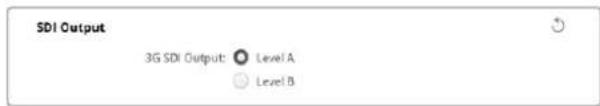
Tally-ндикauя
Ytobb BkIouhbpamKn Tally-uaKauH na Moden Blackmagic SmartView 4K G3, bIepeHte onuEnoBleTaly Ovrride.3a fynKcna CoBmecTma c prdom kamep, BknOyAra Moei Blaekmigic URSA Mini Pro 4.6K, URSA Mini Pro 12K u URSA Broadcast G2.
IopKJIouHtE SDI-BbXoBbl KAmepb I K MmKUepy ATEM n Ko BxOdy 1nnn 2 Ha SmartView 4KG3. CoeINHtene nporpaMMhbl BbXoD ATEM c SDI-BxOdom KaMepbl.
Korda yctpoictBO ATEM nepeknouaet kamepy Ha nporgpammbn BbIbO,Ha SmartView 4K G3 NOBJIETcK pacharpaKa Tally-uhnkaun. Ppi nepexode B pexm npedbapntbHoro npocmotpa OHa ctaHOBITc 3eHeOH.

Hactpoika Display
Ppna paOte c SD-BnDeo ero moXHO macuTabupobatb dner 3anonHeHnB Cero dinCnne, yctaHOBB COOTBETCTByounni FnaKOK.
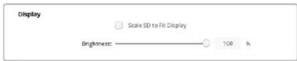
IpynpOBKn npKoCTM MOHToPA nepeTaunte cnaepB BnBn BnpBO nbo BBnTe COOTBeTCTByIOooe 3NaueHne B npOeHTax B uCNOBOM NOE.
C6poc
YTO6bI BOCCTAHOBNTB nepBOHauaHbIe napAMETpbI yCtpoiCTBa, BB6epnte Factory Reset. Nocne Haxatn KHOHKn SET NOBHTc coo6ueHHe c npocboon noTBePdntb deNCTBHe. HaxmTe Reset.
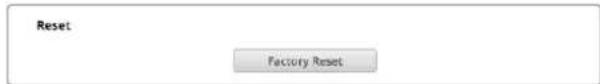
Вкладka 2110
Ha Bknaide 2110 coepkaTcHacptpoKn Mapuyn3aun IP-notokOB SMPTE 2110 nnapametpyrehepatopa PTP.
HactpoKn npneMHnka 2110
IcnoJIb3yIte daHHbI pa3den MeHIO, yTO6bI HApBaNTb BXOJaUe ICTouHKnHa MOHTop SmartView 4K G3.
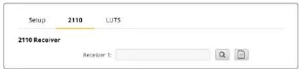
Mapytnzaia Bxodraero notoka
1 Haxmte Ha Lyny cnpaba OI nonI npemHnka. Ha 3kpahe noBtca OKHO CO cnNcKOM IP-y3noB I npbIKOB nCTOCHNKOB DnBCEX DOCTYHBx B CETNIOTOKOB 2110 IP.
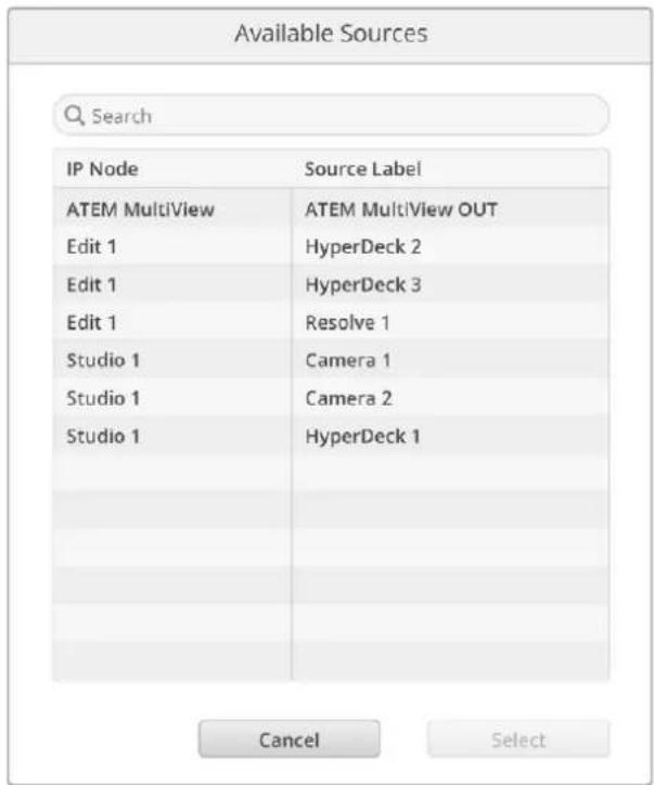
2BbIepeTe DoctynHbI NoTOK n3 cnNcKa HaxMnTe KhoNky Select. OkHO 3akpoetC, n6ydet BblONHeH Bo3BpaT Ha BknaDky 2110 yTuNTbI HAcTpoKn. NcToUHKn BxoJaEero CnHaJana oTo6pa3ntcra Ha MoHnTope SmartView.
NapaMetpbirehepatopa PTP
B daHHom pa3dJe moXHO n3MeHnIb HAcTpoKn BcNyUe rO yCtpoNCTBa PTP.
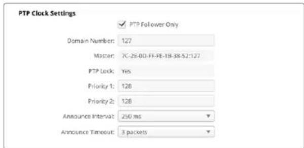
Ipi noeknuehen peeHna SmartView 4K G3 K cetebomy kOMmyaTopy 10G c rheepatopom PTP MOHTOP Heo6xOIMO nepeBecTN B pexIM NOUHeHHoro yCTpoiCTBa, YTObI npedOTbpaNTb KOHnKT CnHXPOHN3aun. Ecn moelb coeHNnHa nAprrmyo C dpyrIm IP-OBOpyDobAHnEM 2110, HapnpMep KOHeBeprom Blackmagic 2110 IP 3x3G, Bblepnte OHy eHNuBy KauectBe IOdUnHeHHoY, yCTaHOVB COOTBeCTByUoNn fJaxkO.
Homep Domena
BBeHnTe HmOp DomeHa, COoTBcTbYIOU 3NaueHIO BedyIero yctpoIcTaPTP. Ka npabInno, OH coCTaBnIe127, Ho erO moXHO I3MeHHTb, yKa3aB b None dpyroe uICNo.
TnaBn aDpec
B daHHom none oToobpaxaetcMAc-aDPEC Beyuero yctpoCtBA PTP (oTdNbHoro peuHnI IN IP-KoHBePtepa, HapnPmep MoeNl Blackmagic 2110 IP Converter 3x3G).
CnHxpoHn3aunc PTP
B daHHOM none yka3aHo, yTo yctpoiCTBO cHxpoHnIPOBaHO C rHepaTOpom PTP uepe3 EternetcoeINHeHne.
PnpOpntet
Ecnn dnn MOHtopa SmartView 4K G3 He Bb6pana Hacptpoa KPA TPT Follower Only, moeB MoKeT BbINHnTb fynHKUIO BeNyUeO yCTPOIcTBa. CoOTBeTcTByUoU npOpnt TneKO 3aDaTb B NoJax Prioity. HEm MeHbue YncNo, Tem OH BbIe.
Hactpoika nHTepBaIa nOxuaHa
IOnla HacptpoKn INTepeBana n OxkndHn DOJXHbI COOTBeCTBOBaT CneuNpKaunm BeDyueero yctpoiCTBa PTP, KOtOpoe o6bUHO nepeaet COoBSeHn CNHXPOH3aUN KaxdIe DBe CEkyHdbI nn 2000 Mc. YTo6bl N3MeHHT bactOTy OTnpaBKN daHHbIX, BOCNoJIb3yTEcb MeHIO 3aDaIte npyroE Bpem. NocTyHbIe DNanao3OHi 3abncrT ot napametpo Rehepatopa PTP.
Peectp NMOS
KoHpyaIPOIINpeectpa NMOS IeKIO BBeCTN BpyHyIO B COOTBeTCTByIOeM Ione. KpOMe TOrO,MOXHO 3aDaTb erO ABTomAtueckoe OOBApYKeHne B CetN.
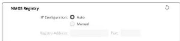
Bkndka LUTS
PeueHne SmartView 4K G3 no3Bolraet BecTN MOHTOpnHr n3o6paKeHHc n omoIbIO 3D LUT-TabNt.3To daT BO3MOXHOCTb HAcTpaINBaT yCTpoCTBO C nCNoJIb3OBAHNem npOpeCCNOHaHBHX cpedTB KaIIbPOBKN nn pOcMaTPBaT MaTePnaJ B TOM BIne, KOtOBu MaKcIMaJIbHO np6NIkEN K KOHeHON BepCN NocNe rpeDnHra. 3D LUT-tabNtBu TAKKe NOMaOT eKcnepmEnTHpOBaT c pa3HbIMn UBeTOBbM cxEmAMn.ДЯnx zarpy3kn Ha SmartView 4K G3 nCnoJIb3yOT yTnIHTy Blackmagic SmartView Setup. TaK kAk MOHTOp noDaePxNBaET paJIbIc paSUnpeHnEM .cube, donyckaetra paOta C CO6CTBeHNbIMn TabIzamn, co3DaHHbIMn B npINOxKeHHn DaVinci Resolve. POnpO6Hee O co3DAHm faiNob CM. pyKOBODCTBO NO DaVinci Resolve.
PopdoK 3aRpyaKn 3D LUT-tabn
1 3aynctte ytniHTy Blackmagic SmartView Setup.
2 Haxmte KhoNky 3arpy3kn dny nepBou LUT-tabnUcbl. OTkpoetc daanorOboe okno nny yka3aHncooTBeCTbYIOJero nytn. BbIepnte Heo6xOumbI paun c pacuHneHem .cube, 3atem Haxmte Open.
3Длгпрсмогра загужehн tabиь bblбeрпte 3D LUT 1 ha naheи ynpaBneHЯ SmartView 4K 3G.Длг OTКLOчEHЯ HaxMITE COOTBeTCTByOuYIO KHOnky eue pa3.
YTo6b3aRpy3ntb BToPyIO LUT-Ta6nCy, BbInOnHnTe aHaONrHuNhe DeiCTBnIy 3D LUT 2.
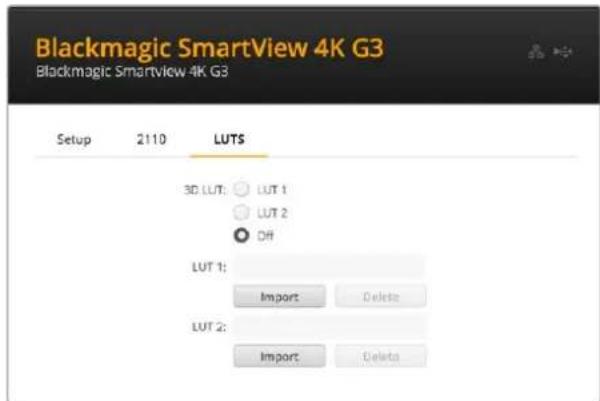
ДяЗагуэк3D LUT-ta6núьHa SmartView 4K G3нспьayкутунnty Blackmagic SmartView Setup
SmartView n SmartScope Duo 4K
PeueHnraSmartView Duo (MaepnB vcpomate do HD 1080p/30) n SmartScpe Duo 4K (ctaHapbH Dc npoBknapoBou HacToOnu Ultra HD do 2160p/30) ochaueh npoN He3aBncmbix 8-IOMOBbIX KK-dncnneEB.3TO IO3BOJAE T OHOBpeMeHNO OTcIeXNBATb DBa OTdJIbHbIX BVdeOCHHaHa NNN BvIBODNTb OINH NOT KE ICTOHNK Ha Oba 3KpaHa. B daHHOM pa3dene pykoBODCTBa ONICahbl pinnCInbI paobTb C hactpoiKaMn yCTpoiCTb SmartView Duo nnn SmartScope Duo 4K.
Ppi paote co SmartScpe nnn SmartView Duo Bb6epnte HxkHb moHtOp: Left Monitor (neBb), Right Monitor (npab) nnn Both Monitors (06a). Ecnn nncno3yertc hactpoika Both Monitors, IIObIe N3MeHeHraKoCTN, KOHTpaCTHOCTN nnn HacblueHHOCTN 6dyT npIMHeHbC K oBOUM MOHtOpam.
Hactpoika Display
Pn paOte co SmartScpe packpbIbAIOueecm MeIO Display codepKNT DocTyNHe iHdkaTOpbl npametpo. T06bl BbIbOnt b3o6paXeHne 6e3 Hdkaun, Bb6epnte onu Video Monitoring.
Hactpoika Set
I03BOJIaHOT N3MeHnTb npaMeTpbl npKoCTN, KOHTpactHOCTN n HacbIeHHOCTN C nOMOuBIO COOTBeTCTByUOxncnAidepOB. Ha moEJnx SmartView n SmartScope doctynhble NaCTPOIN pa3HrTcR.
Hactpoika Identify This Device
IocTabe TpKd nHa cHToKn Identify This Device, OToBbOToOpaKaTb 6eNyIO pAmky Ha dncnnee ToTo yCToPcTba, KToPooe BbIpaHO BytInne Blackmagic SmartView Setup.3To oBleercaet ndentnFokaun, ecnn K IokaIbHO CTe NnoKnHoy HeckoJIbKO MOHITopoB SmartView nSmartScope.
PnncnoB3OBAHm COBmecTHo C hactpoiko Both Monitors 6aenpaamka oTo6paaetcHa 0boux ducnnex MOHITOPOB SmartView Duo n SmartScope Duo 4K.
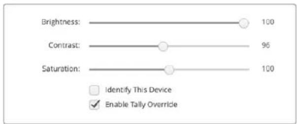
IpeBnBte cnaep BnpBO nBneO nMaMeHn Hactpoek Brightness,Contrast mN Saturation. TTo6bBn3yAaHo IeHTnPcnpoBaT bVbpaHHb MOHtOp,NoCTaBTe pJaxok dIg onUnIdentify This Device.
Hactpoika Enable Tally Override
YtobBkIIOHTb pAMKn Tally-IMKauuHa MoeJX Blackmagic SmartView Duo n SmartScope Duo 4K, Bb6epnte daHHyO onuio. 3Ta yHKnra COBmecTIma c TaKmN kamepaMn Blackmagic Design, kak URSA Mini Pro 4.6K G2 n URSA Broadcast G2.
IopKIOHTe SDI-BbXoJ KAMepb Ko BxOy A NnB Hs SmartView Duo nN SmartScope Duo 4K. CoeINHtE nporpaMMhB bXoJ BnDeomKwepa ATEM c SDI-BxOJOM KAMepb.
Korda Bndeomnkwep ATEM nepeknoaet kamepy ha nporpammbbBbOd, ha SmartView Duo nSmartScope Duo 4K nOBnTcKpaHpaMka Tally-nHnKaun. Pn npexoe b pexm npedBaPntbHorpoocmotpa OHa cTaHOBnTc3eHeHo
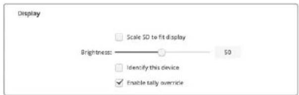
Korda KMOHITopy SmartView Duo noKnquHeKaMepa Blackmagic URSA Mini Pro nnu URSA Broadcast, nna BbOda Ha Hero pAMOK Tally-nnkaunn BbBepnte onuEnable Tally Override
Pa6ota co SmartScope Duo 4K
O630p монитopa Blackmagic SmartScope
TpauuHbIe ocunllnorpaBbl, nCNoJIb3yEmbIe B NoCTnpOn3BOOCTBe H a TeNeBUNHeHHN, AIBJIOCTc OueH DOpOFOCToAUMN yCTpOJCTBaMn I pR N TOM CNOOCbI BbIBOHTb Ha 3KpaH TOIbKO IO ONDHom npaMeTpy 3a pa3.
MOnHTop SmartScope Duo 4K Imeet DBA dncnne, KOtOpBie no3BOJrO T B peaHbOM BpeMeHH KOHTpOIpOBaT pa3nUHbIe npaMetpy CnHana, np3OM n3MeHeHne cNoCob6a npedCTabEnHc NomoubIO ytniMbI Blackmagic SmartView Setup cpa3y npimHeTcK n3oPaxHeHIO Ha ekpaHc YcTPOINBa. KaXdbI BxOJaun NoTOK, NoCTynAIOuN chPeE cKBo3HO SDI-INHTepFeIC, MoXHO HapRaBnTb Ha IIObO IN3 DBYx DnCnneeB; HApIMep, INndKaToPb CnHana -Ha npaBbI, a camO n3oPaxKeHne -Ha neBbI.
INdkaToPbI, oTo6paKaMaBHe Ha SmartScpe Duo 4K, nERko Bb6paTb c NOMOu yTNNTb Blackmagic SmartView Setup.ДЯ STOrO nepeiDnTe K MeHIO Display.
IopoeoHee O Ha3HaueHn KaJdoRo IINHdkaTOpOB IN CNOcO6ax IX INCNoB3OBAHn CM. HnKe.
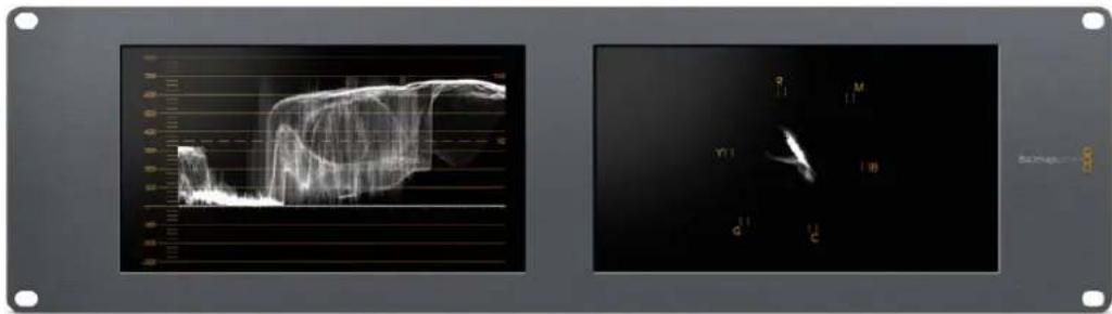
Cnmoouyntbbl BlackmagicSmartViewSetupHaDcnnmMoHntopaBlackmagicSmartScpeDuo4K MOXHO BvBOHTb pa3NNHbE INNkAtOpbI
Опuna Video Monitoring
Korda nHa HactpoKn Display nCnoB3yetc onuY Video Monitoring, Ha ekpaH BbIbOHTc noctyaiooee Ha BXoNIO6paxeHne.
Дя SD-crHana B MeHIO Set moKHO BbIpaTb nponopun KaJa 4:3 n16:9. IIObIe NImeHHe NaCTpoE KpKoCTN, KOHTpactHocTN Hn HacBIsHeHHocTN JERKO Cpa3y yBnTeB Ha DnCnlee. OHI npIMeHryOTcT ToJbKO dR OTObpaXeHn Ha MOHTope, HO He 3aTpparBaIOT HenOcpeDCTBeHHO Cam CInHaI.
OINH INCNNE MOXHO HcONb3OBaTB dIg BbIODa BNDeo, a npyro - IJn OTO6paKeHH INNkATOpOB. DnI 3TOr COeHNHTe cKBO3HO SDI-BbIXoD MOHITOPa N° 1 n BxOD MOHITOPa N° 2 C NOMOsbIO KopoTko KaBena.
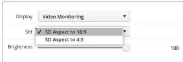
B MeHo Set yuHnHb Blackmagic SmartView Setup nla SD-Bnneo MoxHo Bb6paTb npopOpmKKaDpa 4:3 nn16:9. Dn npocMToPa aHaMoppHoro n3o6paKeHHN mOnb3yETcB TbopaOnn.
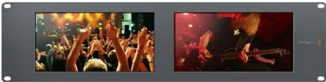
Onuia Video Monitoring nna Hacptpokn Display no3Bolrae BbOaHtB 3o6paXeHne B TaKOM Ke Bunde, B KaKOM OHO NOCTynaet Ha ekpan TeneBu3opa nn MOHITOPa
Dncnnen oopmbicnHa
3TOT INHINKATOP Cnyknt IaI OTo6paKeHHa FOpMbI BOnHb I CnFpOBOM BIne NcNoJIb3yETcA DnMOnHTOpHra HAcTPOKn JRPKOCTN BuJeO.
B OTNIuHne OT TpaNIOHHbIX MOHTOpOB, KOtOpBle cnoocbHb paOToTb ToIbKO c aHaIOrOBbIM KOMNo3nTHbIM BIndeo B cTaHdApTHom pa3peWehn, ycTpoCTBo SmartScope Duo 4K NOndepKnaBaET SD, HD n Ultra HD. TaKo fynHKUHOHAN no3BOJrE TBeCTN nonHOeHHbIKoHTpObl yPOBn IpKoCTn DaXe npaPoTe C cΦopMaTm BBICOKO qETKoCTn.
Длг STOrO BbIepeHte onuHo Waveform B MeHIO Display yTuNTbI Blackmagic SmartView Setup. YTo6bI He DoNyCTnTb 3aCBETK nIIN 3aTeMHeHn, yPoBeHbApKocTn He DoJxH eOnyckaTbcn HNKe O% INoHNMaTbCBA BiWe 100%.
ΦopMa BONHbI - 3TO rpaFnueckoe npedctabHeHne n3o6paKeHn, noka3bBaIOuOe ypoBn IpkocTcPacnpedeHHeHm B rpaHnucx KaJa. HApPImep, eCNI 3acBeueHa cactb He6a, 3TO 6ydet 3aMeTHo HA COOTBETCTBYUoiem yuaCTke.
BnD pOpMb BOHb 3aBnCt OT cBemOCHOro MaTePnAna. Pn MOHITOpHRe KaPOB C BbICOKO KOHTpactHOCTbIO NOIyToHa MOrY OTCyTcBOBaTb. Ha PnCyHKe HIXe NOKa3Ha φOpMa CNrHaJa C paBHomepHOn EKcNo3uNei: NeBa YAcTb COOTBeTcByEt TEMHOMy yAcTky, a Oblaactb OT cHTpa K npabOMy KpaIO KaJa -0onee CBeTbIM 3OHAM.
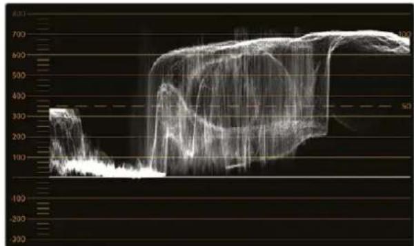
Ducnnne FopMBI BONHbIOKA3bBaETypOBHN npKoCTn
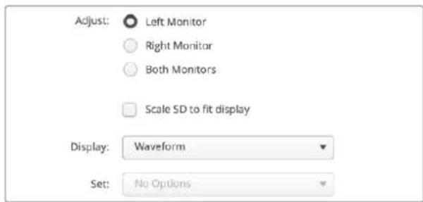
Yto6bIyBnDeTbnapMeTpblpKocTcnHana,Bb6epnte onuWaveformdnaHactpoiNDisplay
BekTopockon
TOT INHINKATOP NOBOLIET NOLYHTB INHOFOPMAUIO O CBetAX BnDEOCIRHana. BbIEepnte 100% n75% B MeHIO Set B 3aBNCIMOCTN OT NCNOJb3yEMORO TECTOBORO CnIHANA CCBETHBIMN NOLOCAMN.
HOrda cHTaOT, YTO BeKToPOCKON No3BOLnEe BbIbIaTb HeKOppeKTHbIe yPoBHcNHaHa. IDoobHOe MHeHne OUsOBOuHO, NotOMy TTO dJa 3TOrO HxKHO BuDeTb 3HaueHnra CBetHOCTN I apKoCTN. YTObI opPeJeNTb HeKOppeKTHbIe yPoBHn, TpeByETc DaCnNei RGB Parade. Lbeta, np6JInxKeHHbIe K bENOMy INn UepHOMy, He MoYr 6bITb TaKIMn Xe HaCbIeHNbIMn, KaK BoJee rny6okne cBETA, fOpMnpyUOune pa3NIuHbIe OTehKn. NpckOBKy BeKToPOCKON He noka3bBaet 3HaueHnra JpKOCTN, eRo HeNB3r IcNoB30BaTb ToNbKO dJa BbIbIeHnra HeKOppeKTHbIX yPoBHne.
BektopoKoN IealbHo NdoXoDnI Iy npOBepKn Koppekun cBeta B n3O6paKeHH, noLyehHom Co CTapbIX aHaNoRObbIX BInDeonneHok. Dny 3TOrO DOCTaTOUHO BOCpON3BecTn Hkyhbl ppaMeHT, a 3aTeM CKopkeKTnpOBaTb NapaMeTpbl cBETHO TToHc NOMOuBIO uKaJIb.
BektopoKoN 6yIeT He3aMeHIMbIM INHCTpyMeHTOM npn BByIOJIHeHH rpeiINHra,notomy OTO OH no3BOJare IPOBepNT balaHc bEnoro.Ecn n3O6paXeHne cOedePXT KAKoI-NIOO cBeTOBOI OTeHOK, INΦopMaUaY O HEM 6yIeT CMeUaTbCRA OT cHTPa BekTopoCKOna N MoKet IMeTB DBe TOckN. Ecn B cInHaJe NCNoJIb3yETcraIaSeHne,To o6bHuO B cHTpe DnaIparMMbI OTObpaKaETcT ToUKa,NOTOMY 7TO BO BpEma RaWe HnBaTe OPeDCTaBJIeT C60B UcpHOe NOIE. OHO MOKeT cLYKHTb NOe3HOJ KOHTpoJIbHOJ TOckO, C NOMOUsIO KOTopoJ IerKO YcTaHOBtB OTCyTCTBne INΦopMaUu O cBete.
Ecnn n3o6paqhenne coepknt kakon-lno 0BETOBO ONTEHOK, INHOPMaun O HEM byt CMeaTbCRAOT cHTpA. CTeNEHB CMeueHNA 3aBNCNT OT INHTECNBHOCTN 0BeTOBOrO OTENKa n 3aTparnBaet yactKn, oTo6paJauOnne kak CBtIbIe, tAK N TeMHbIe TOHa. BnaOrapr EToMy BEKTopoCKON MOXHO IcNoJIb3OBAtB dIyUdJeHNA 0BETOBBX OTeHKOB INCOxpaHEnn npabInhoro balaHca bEnoro.
BektopoKoN no3BoJnEeKoppeKTHPOBaTb cBeT 6e3 do6abHeHHeKeNaTeNbHbIX OTteHKOB B oIaCTx CBeta H eH. XToA bAlAnC cBeTa MoKHO KOHTpOJIPOBaTb C NOMOuBIO RGB-dIcPnEe I BeKTopoCKona, npoBneMbI c 3Tm NapaMeTpom npOSe OTCneDntb BO BTOpom cnUyae.
Pn yctahOBke zBeta chenobueeckoro nla napamTp hacbIeHHOCTNO bHIO DOJIKeH COOTBETCTBOBaT noLOXeHNIO 10 cAOBHa BektopocKone. OHO Ha3bIbaTeC IINHeN E TeNECHOR TOHa? N NO3BOJAE TdoBtca TaKORA ZBETA KOKN, KOTOpBII oyDeT BvIRJaTeB eCTeCTBeHHbIM He3aBNCIMO OT pacoBOI npHnADJeXHOCTN ChIOBeka.
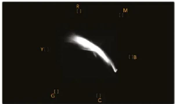
JIINHNA TeneCHORO TOHa COOTBETCTByeT NOIOXKeHNIO 10 YacOB Ha BekTopoCKone
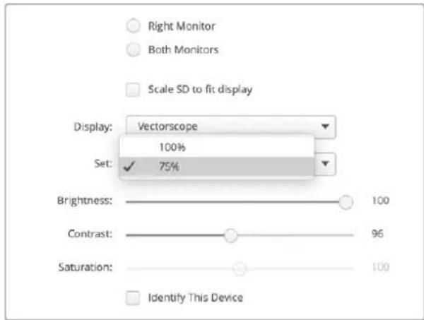
Bb6epnte 100% nnn 75% B 3aBnCmOCTOn OT cNoJb3yEmoT ETeTOBO CnHana CCBETbIMN NIOcAMN
Диспел NapametpoB
Dncnneu RGB Parade n YUV Parade no3B0JIOI NOyUHT bHOpMaUHO HeKOppeKTHbIX ypoBHx CBeta n IealbHo IOXODT dNr rpeiINHra.
Пи ВьлпнHeHи CBETOKOPKEKи Bb6epnte RGB Parade B MeHIO Display.ДиСпЛe RGB Parade OTOБражаET NO OTdIeNbHocT NOnHyO ShKaIy KpaCHOrO, 3eJIeHOrO n CnHero KaHAnOB. Korda I3OBpaxeHne npEcdTaBNeH O TAKOM BInDE, npOSe KOHTPOnIpOBaTB CBETOB O balaHc B OblaCTx CBETA, NOlyToHa H TeHn, a TakXe YdaIaTb HeXeJaTeNbHy ToHIpOBky.
Bo BpemBaIIIOHHeHnZBETOKOppeKmBaxHO CoXpaHrB CnHnB 3aAHHbIX rpaHuax.Ipn yBeIueHmEro yPOBn HxHNO CneITb 3aTeM, YTObI OH He BbIXOIN 3a npedeJIb, ycTAHOBHeHbIe InI napAmetpoB RGB. He3aBncIMo OT nCnoNb3yEmoro O6OpyDobAHnM, MOHTOP SmartScope Duo 4K no3BOJraT BcERda BnDEtbe HeKOppeKthIe yPOBHN RGB-n3OpaKeHn.
OHI MOryI npoAIBaTbCak 3acBcTa IIN 3aTeMHeHne H3obpaXeHn. B HeKOTopbIX CNTEmax rpeiHra ypoBeH cyepHO MOxHO yMeHbIb Hnke O%. PnHaNNH HeKOppeKTHbIX ypoBHeyepHO IIN IX KOMHeHCauN yBEnuIbTe 3NaHeHne Lift nII Gain, Ho y6eDInTEcb B TOM, YTO ypoBeHb CnHaHa He npEblaaet 100%, UToBI He dOnyCTtB 3acBcTKB Obnactx CBeta.
Длп npоверкуюн YUV bblбeпгь Мeну Display onuYUV Parade.Вэтмсуае napametрь яркови Будг OTdileнь OT CBeta noDIObHO TOMy,Кak priHrTO B TeIeBeeaHn.Лeваячыдпспя соotbetcTByetЯрков, a BtOpoN nTrpTeN INHdkatOpby COepeKAT INHOPMaIO OцBetE.YUV Parade no3BOJЯET BbINONHЯТь KANbPoBky CBeta NO TectOBIM WAbNoHaM ДлгКоррекTHOH nepeDAuN BeaTeNBHO rCnHana Ha Зралы ТелевиЗОрВ.
Bnaorapra uBeToKoppeKuIM MOxHO nOlyuHTb MaKcMaJIbHO KaueCTBeHHoe I3o6paXeHne C coXpaHHeHem yPoBHeN cRHaNA B 3aDaHHbIX rpaHnuaX.
TepMHbI cBETOKOppeKuM
TeHH-TEMHbIe TOHa.
rMaMa -CpeHne ToHa.
CBet-CBETNbIe TOHa.
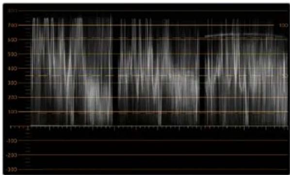
ДиСпнeR RGB Parade
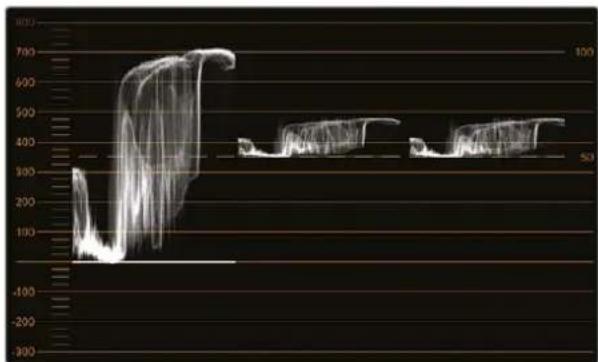
Диспай YUV Parade
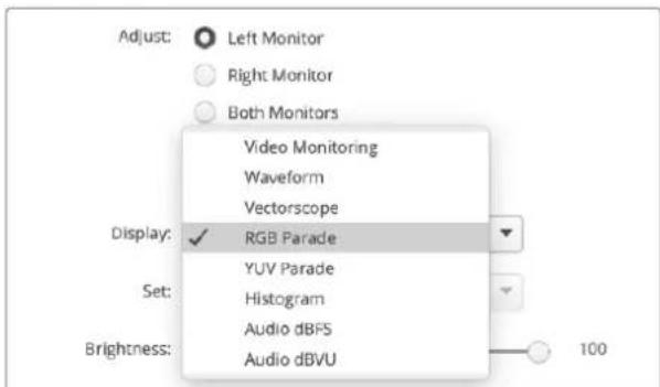
BpackpbbaioeMcMeHIODisplayBb6epTeDncnnenRGBParade nnYUV Parade
ΓnCTOrpamma
C rncrporpmmo yae Bcero nmeot deo rpaqneueckne n3aHepb n onepatopk kamep. OHa nokaabaet pacnpedeene H eemeHTOB n3obpaxeHnO t benoK uhehomy UBeTy nnoBnReT yBnTeB HeoocTaTOHyIO nn N36blTOHyIO kcn03uio. C ee nomouko moxHO TAKKe KOHTPOINPOBaTb N3MeHHeNE BInDeo Pn KoppekTIpOBKe cpeHNx TOHO.
B IeBOI qacn DnCnnner cospedtoueHa HOpmaunr O TeMHbIX ToHax, B npaBOI qacn - O CBetnbix. KaK npabInno, OHa DoJHKHa HaxoDntbc B INTEPBane ot 0% do 100%. PpN HeIOCTaTOOH nn N36bToCHNO EKcNo3uINn HOpmaunr O6 N3O6paXeHNn BbxOHT 3a 3TN KpaHHe TOCKN. DepeKtbl EKcNo3uINn OCNoXHraT O6paOToKy N3O6paXeHNn n erO UBeTOKoppeKUHO Ha 3TaNE NOCTPPOUN3BOIDCTBa, NOtOMy BO BpEM CaEMKn BaXHo CneDnTb 3a Tem, YTObI rNCTORpAMMa He ONyCKanacb Hxke KpaHNe JLeBOI TOUYKN H He NODHMnAanac B BIwe KpaHNe ppaBOI TOUYKN. B 3Tom cnYueae konOpncST BydET IMeTB BoJIbSe CBoODbI npn BbINOnHEHNr PReiDnHra.
Korda Bo BpemzBcToKOppeKunn npmHnIOT 3acBETky nnn 3aTeMHeHne, rntOrpaMaOToPbXaet 3OT 30fKeT NOKa3bIbAeT CTeneHb HeoctatoyHO HnN 36blTOOH 3KcNo3nU. CpeHnE ToHa no3BOJnIOT Do6nTBCxOHO 30fKeTa n np 3OM coXpAHnTB 60nbwe Detanei.
TnCTOrpamMa He IooXoIIT DnI npOBepKHeKOppeKTbIX yOBoHEn, XOT DaET Bo3MOxHOCTb YBnDeTb HEOIyCTMblE 3NaueHnCBETbIX N TEMhIX TOHOB. TaK KaK OHa He OTobpaKaet Ubeta, HEKOppeKTbIe yPOBHN HeNb3A yBnDeTb daxe npuNX HaNcHm. IaN BbIABeHn TaKnx yOBoHEn HyXHo nCIOJIb3OBAbT bHdNKATOP RGB Parade, KOtOpbi NOKa3bIaEt Ka KEBt, TaK INPkoCTb 3JeMeHToB BVideocnHana.
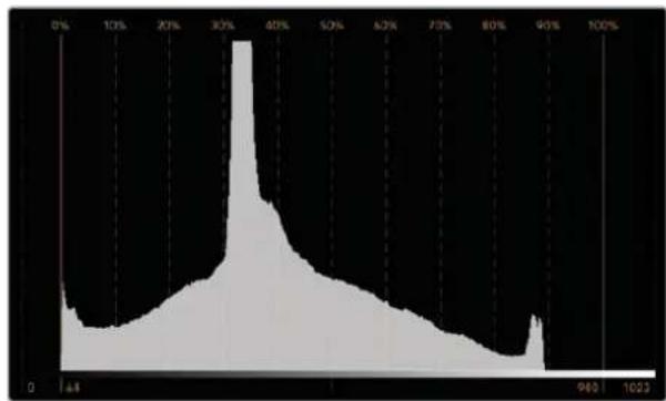
Tnctorpamma noka3bIbaet pacnpedeneHne 3nemehTOB n06paKeHHN O BENORK UePHOMy CBety
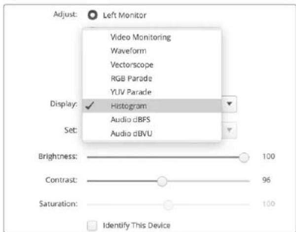
Bbepte Histogram B Meio Display yuBlackmagc SmartView Setup
YpoBHeHb 3Byka
3TOT INHINKATOP nOKa3bIaBETyPOBeHb 3Byka, BCTPoeHHoro B SDI-BnDeo. N3 noctynaiooero notoka n3Bnekaetcdo 16 kaHaoB aydno, KOtOpbIe oTo6paKaiaotcB pexime dBVU nn dBFS.
INdkkaTOp VU noka3bBaet cpeHne ypOBn CnHaIa, npocB npimeHeHH N aAe BCTpeyaeTcna OobopyoBaHN npdeBldyueero nokOJIeHNA. OH OTkAnIbPoBaH B COOTBeTcBNI CpeKOMeHndaunm SMPTE (ToHaJIbHBI TeT-CnHaI 1 KΓu IMeET 3NaueHne -20 dBFS).
INHdkatop dBFS npedHa3haeH dIa Bcero cnpoBoro aydnocnHaI N obuHIO nCnoNb3yETcB COBpeMeHHOM o6OpyDobAHIN.
AynometpB npaboi yactn 3kpaHa oecneuBaET MOHITOpHr DByx KaHAnOB 3Byka, KOToPbIe BbIbpaOT B MeHIO Set (Phase scope to 1 & 2, Phase scope to 3 & 4 n. d). OH oToobpaKaET MOHOI IN CTpeoOdopOxy B DByxmepHOIN CNTeMe KoOpDInHAT N No3BOJRAET BbIaBnTb HApUWeHne balaHcN HeCOBnaDeHne no fae. MoHOIpOoxKa Byet npedCTaBHeA B VnDE eHNuHOr BEPTKakbHOI nnHn. Ecnn noka3Ha rOpuzoHTaBnH a nnHn, IMeet MeTO cDNr fAsbl, YTO MoXe TnpBeCTN K NOtepe CnHana npi nepeDaue Ha dpyrooe obOpdyObaHne. HecOBnaDeHne no fae - ODA H3 cambIX qactbIX TexHHuecknx npoBEm npi NCNoBzOBAHn BoJIbWoTO KOnUeCTBa coEduHEnH.
Pn MOHITOpINHRE cTepeoOpOxKc ciHaI NmEeT OkpyrNyIO fOpMy, OToobpaXaR pa3HnUy Mekdy npabIM n IeBbIM ayDnOKaHAnAMn. Yem BoJbUe cTepeo3ByKa coepKntC B ayDnOdoPoxKe, TeM 60lee 3akpyrIeHHbIM bdyET n3OpaXeHne Ha 3kpaHe. Ecln ayDnO coepKNT MInHMaJIbHOe KOJIueCTBO cTepeo3ΦfKeTob, fOpMa CnIHana BbITARNBaETCR BDOJIb BEpTKaJIbHOJ LHNII.
PeybOboHNO OToobpaKaJaTcKaBepTKKaJIbHa JINHnA, a My3bIka Co cTepeoΦpKeTAmu — KaK 3JIInnc nn Kpyr. 3TO o6bAcHReTc TEm, YTO ayDnOMeTp noka3bIbaeT MOHOdoPoxKy ka L+R Ha BepTKaJIbHoN Ocn, a CtepeoDoPoxKy — B BnDE pa3HnUbl L-R Ha rOpn3OHTaIbHOn ocN.
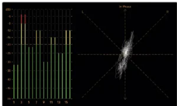
HnKaTOp ypoBHa 3ByKa noka3Baet NkOBBe 3HaueHnI 6anHC ayno
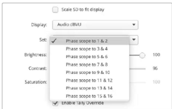
B MeHIO Set BbIepeTne npy ayDnOKaHaIOB dny MOHTOpuHra
CeteBbIe npaMeTpbl
IMRA MOHITOPA
ДяубсТВаидентиФКИСМохно ИЗМeHNTь ИмЕнHaMOHITopOB SmartView Duo nSmartScope Duo (Hanpimep, «ВhecуdnHbIe kamepbI 1n2«, «MHorOOKOHbIbBxOД«, «4K-BuDeo» n t. d.).
YTObI N3MeHnTb IIMy yCTPOINCTBa, y6eDInTEcB, YTO OHO NODKnIOUeHO uepe3 nopT Ethernet nnn USB. OTKpoIte yTNIHTy Blackmagic SmartView Setup u BB6epnte 3NaOcK HAcTPOE KIOd IMeHem MOHITOPa. B COOTBeTCTByIOUe cekun Ha BknaJKe cTeBbIX npaAMETPOB BBeDNTE Ha3BaHne yCTPOINCTBa. Pn INCNOJIb3OBAHm HeONyCTUMOro BapHaNTa NOBnTcN ppeDynpexKDeHne. EcnI φOpMaT IMeHn KOPPeKTeH, PAnOM C Hm OTo6paNTcRΦlaXok. HaxMITE Enter (BBOD) c KNaBnAtypbl, YTObI NODTBepNDtB N3MeHeHne.
CeteBbIe npaMeTpbl
YTo6bI N3MeHnITb CeTeBle HacTpoKn C nOmoUIO yTuINuTB Blackmagic SmartView Setup, MoHITop DOnJKeH 6bITb NODKlOUeH K KomNbIoTEpy Hepe3 npT USB. NpT Ethernet He npedHa3NaueH dJa 3Txx ueJe.
Iyo mOnuHIO dIy ABToMaTHeCKO rONUeHnCeTeBOrIP-AdpeCa nCNoB3yETcHAcTPOKa DHCP. Ecn MoHITOpb i SmartView n SmartScope He o6hApXKeHb, cKopee Bcero, IM He 6bln npncBoeHb IP-AdpeCa c NmOuBIO npotoKoHaDCHP. B 3OM Cnyae Heo6xOaMn BOBectn COOTBeTCTByUOuHcEteBBie HAcTPOKn BpyHyO B ONuCAHOM HNKe IopJKe.
YcTaHOBkA cTaNHOrO IP-aDpeCa
1 CoeINHTe MoHITop SmartView Duo nnn SmartScope Duo c KOMNbIOTepom uepe3 npT USB n oTKpOte yTuNTy Blackmagic SmartView Setup.
2ПодключehHoe yctpoIcTBO 6ydt ABTomaTnueckn paCno3HaHO n Poka3aHO Ha hauJIbHoI ctpaHnce Blackmagic SmartView Setup, a pYdOM cero ImeHem noRbNTc3HaQOK USB. UeKHTe NO CUMBOIy MOHITopa.
3 Otmte Ione ctaunHoro IP-aDpeca, a 3aTeM BBeNTe COOTBcTByOuHe HAcTpoKn. Pn yctaHOBKe daHHbIX npaMeTpOB o6paTntecb 3a NOMOsbK CnCTemHomy aDMNHCTpaTopy.
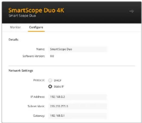
4 Nocne 3anonHeHn DaHHbIX HaxMnte Save.
Blackmagic Design products support 3G-SDI video, which allows twice the data rate of traditional HD-SDI video. We thought it would be a really nice idea to add 2K film support, via 3G-SDI technology, so we could simplify feature film workflows. With the popularity of Blackmagic Design editing systems worldwide, now thousands of people can benefit from a feature film workflow revolution.
This information includes everything product developers need to know for building native 2K SDI equipment. Of course, all Blackmagic products can be updated, so if the television industry adopts an alternative SDI-based film standard, we can add support for that too!
Frame Structure
- Transmitted at 23.98, 24 or 25 frames per second as a Progressive Segmented Frame.
Active video is 2048 pixels wide by 1556 lines deep.
Total lines per frame : 1650 - Active words per line are 1535. One word consists of a 10-bit sample for each of the four data streams, i.e., a total of 40 bits. See the diagram named Blackmagic 2K Format - Data Stream Format.
Total active lines : 1556
Total words per line: 1875 for 23.98/24Hz and 1800 for 25Hz.
Fields per frame: 2, 825 lines each
Active lines located on lines 16-793 (field 1) and 841-1618 (field 2).
Transport Structure
- Based on SMPTE 372M Dual Link mapping and SMPTE 425M-B support for mapping SMPTE 372M into a single 3 Gb/s link.
- Timing reference signals, line number and line CRC insertion is the same as above.
- During active video, 10-bit Red, Green and Blue data is sent in the following sequence:
- Optional ancillary data is inserted into both virtual interfaces.
-
At present, only audio data is included: as per standard HD audio insertion (SMPTE S299M) the audio data packets are carried on data stream two and audio control packets are carried on data stream one.
-
Data stream 1: Green_1, Green_2, Green_3, Green_5...Green_2047
- Data stream 2: Blue_1, Blue_2, Green_4, Blue_5...Green_2048.
- Data stream 3: Red_1, Blue_3, Blue_4, Red_5...Blue_2048.
Data stream 4: Red_2, Red_3, Red_4, Red_6...Red_2048.
Blackmagic 2K Format - Vertical Timing Reference
This diagram shows the vertical timing details with line numbers and Field, Vertical and Horizontal bits for the Timing Reference Signal codes.
| Field 1 Active | ||||||||||||
| F1000 | 0000 | 000 | ||||||||||
| V11111 | 0000 | 11 | ||||||||||
| LINE # | 1650 | 1 | 2 | ... | 14 | 15 | 16 | ... | 792 | 793 | ... | 825 |
| Field 2 Active | ||||||||||||
| F | 0 | 1 | 1 | 1 | 1 | 1 | 1 | 1 | 1 | 1 | 1 | 1 |
| V | 1 | 1 | 1 | 1 | 1 | 1 | 0 | 0 | 0 | 0 | 1 | 1 |
| LINE # | 825 | 826 | 827 | ... | 839 | 840 | 841 | ... | 1617 | 1618 | ... | 1650 |
Blackmagic 2K Format - Data Stream Format
This diagram shows the data stream formats around the optional ancillary data section of the horizontal line. Note that each active pixel takes up three samples.
| Word#25 PsF | Word#23.98/24 PsF | Data Stream 4 | Data Stream 3 | Data Stream 2 | Data Stream 1 |
| 1795 | 1870 | R2042 | R2041 | B2041 | G2041 |
| 1796 | 1871 | R2043 | B2043 | B2042 | G2042 |
| 1797 | 1872 | R2044 | B2044 | G2044 | G2043 |
| 1798 | 1873 | R2046 | R2045 | B2045 | G2045 |
| 1799 | 1874 | R2047 | B2047 | B2046 | G2046 |
| 1800 | 1875 | R2048 | B2048 | G2048 | G2047 |
| 1 | 1 | EAV(3FFh) | EAV(3FFh) | EAV(3FFh) | EAV(3FFh) |
| 2 | 2 | EAV(000h) | EAV(000h) | EAV(000h) | EAV(000h) |
| 3 | 3 | EAV(000h) | EAV(000h) | EAV(000h) | EAV(000h) |
| 4 | 4 | EAV(XYZh) | EAV(XYZh) | EAV(XYZh) | EAV(XYZh) |
| 5 | 5 | LNO | LNO | LNO | LNO |
| 6 | 6 | LN1 | LN1 | LN1 | LN1 |
| 7 | 7 | CRCO | CRCO | CRCO | CRCO |
| 8 | 8 | CRC1 | CRC1 | CRC1 | CRC1 |
| 9 | 9 | 200 | 040 | ANC/Audio Data | ANC/Audio Data |
| ... | ... | ... | ... | ||
| 260 | 335 | 200 | 040 | ||
| 261 | 336 | SAV(3FFh) | SAV(3FFh) | SAV(3FFh) | SAV(3FFh) |
| 262 | 337 | SAV(000h) | SAV(000h) | SAV(000h) | SAV(000h) |
| 263 | 338 | SAV(000h) | SAV(000h) | SAV(000h) | SAV(000h) |
| 264 | 339 | SAV(XYZh) | SAV(XYZh) | SAV(XYZh) | SAV(XYZh) |
| 265 | 340 | R2 | R1 | B1 | G1 |
| 266 | 341 | R3 | B3 | B2 | G2 |
| 267 | 342 | R4 | B4 | G4 | G3 |
| 268 | 343 | R6 | R5 | B5 | G5 |
Blackmagic SmartView Ethernet Protocol v1.4
Summary
The Blackmagic SmartView Ethernet Protocol is a text-based status and control protocol, very similar in structure to the Videohub protocol, that is accessed by connecting to TCP port 9992 on a SmartView or SmartScope monitor.
Upon connection, the SmartView or SmartScope monitor sends a complete dump of the state of the monitor. After the initial dump, state changes are sent asynchronously.
The SmartView or SmartScope sends information in blocks which have an identifying header, followed by a colon. A block can span multiple lines and is terminated by a blank line.
To be resilient to future protocol changes, clients should ignore blocks they do not recognize, up to the trailing blank line. Within recognized blocks, clients should ignore lines they do not recognize.
Legend
carriage return
and so on
Version 1.4 of the Blackmagic SmartView Ethernet Protocol was released with SmartView 1.4 software.
Protocol Preamble
The first block sent by the SmartView Server is always the protocol preamble:
PROTOCOL PREAMBLE: Version: 1.4
The version field indicates the protocol version. When the protocol is changed in a compatible way, the minor version number will be updated. If incompatible changes are made, the major version number will be updated.
Device Information
The next block contains general information about the connected SmartView or SmartScope.
SMARTVIEW DEVICE:
Model: SmartView Duo
Hostname: stagefront studio.example.com
Name: StageFront
Monitors: 2
Inverted: false
This example shows the output for a SmartView Duo, which has two LCDs.
The INVERTED flag indicates whether the monitor has detected that it has been mounted in an inverted configuration to optimize LCD viewing angle.
Network Configuration
The next block shows the TCP/IP networking configuration:
NETWORK:
Dynamic IP: true
Static address: 192.168.2.0
Static n etm ask: 255.255.255.0
St atic g atew ay: 192.168.241
C u r rent add r ess: 192.168.1-101
C u r rent n etm ask: 255.255.255.0
C u r rent gate w ay: 192.168.4.1
The network settings prefixed with CURRENT show the active TCP/IP settings, and are readily. The CURRENT settings reflect either the DHCP or Static configuration, depending on the DYNAMIC IP flag.
Changing Networking Settings
The network can be configured to use either DHCP or a static configuration. To enable DHCP:
NETWORK:
Dynamic IP: true
←
To set a fixed IP address, supply all static parameters, thus:
NETWORK:
Dynamic IP: false
Static address: 192.168.2.2
Static netm ask: 255.255.255.0
St atic g atew ay: 192.168.2.1
The parameters with the CURRENT prefix are read-only, and show the active configuration, regardless of the static or dynamic setting.
Changing the name, or any network settings, will cause the IP connection to be dropped. The SmartView or SmartScope will restart its networking and advertise its new name on the network.
Changing Monitor Settings
The display settings for each monitor are specified individually. One or more parameters can be modified at the same time and multiple settings can be supplied in one block.
The valid range for numeric values is 0-255. The CONTRAST and SATURATION properties are zero-centered, so the normal value is 127, such that the displayed picture is the same as the original. A value greater than 127 in either channel will cause the contrast or saturation to be increased, and similarly a value less than 127 will cause a decrease.
For example, to set the brightness to 50% and desaturate the image to Black & White:
MONITOR A: Brightness: 127 Saturation: 0
Displaying SD in 16:9
The following command sets standard definition video to display in 16:9:
MONITOR A:
WidescreenSD:ON
Displaying SD in 4:3
The following command sets standard definition video to display in 4:3:
MONITOR A:
WidescreenSD: OFF
Identification and Tally Settings
The Identify flag is transient, and will cause a white border to be displayed around the entire picture for a duration of 15 seconds, after which it will be reset. This feature is primarily aimed at identifying which monitor is currently being configured when it is mounted in a rack comprising multiple units. To turn on:
MONITOR A:
Identify: trade
The IDENTIFY border will temporarily override any other border setting in effect.
The BORDER property can be used to programmatically set the soft Tally colored borders to one of the primary colors: RED, GREEN, BLUE, WHITE or NONE. This setting can be overridden by the electrical Tally signals at the DB-9 input on the monitor itself. For example, to set the soft Tally to green:
MONITOR B:
Border:green
The hard wired tally will always override the soft tally. The full state report will always show the current valid border.
SmartScope Settings
On SmartScope Duo 4K, each monitor can be set to display a different scope. The values for activating specific scopes are mapped as follows:
AudioDbfs
AudioDbvu
Histogram
ParadeRGB
ParadeYUV
Picture (This is the same as Video Monitor)
Vector100
Vector75
WaveformLuma
MONITOR A:
ScopeMode: Picture
In the example above, Monitor A has been set as a video monitor.
Displaying SD in 16:9
The set Video Monitor mode to display standard definition video in 16:9:
MOTOR A:ScopeMode:Picture WidescreenSD:ON
Displaying SD in 4:3
To set Video Monitor mode to display standard definition video in 4:3:
MOTOR A:ScopeMode:Picture WidescreenSD:OFF
When setting one of SmartScope Duo 4K's monitors to audio metering, you can also select which channels to show. The values for selecting which audio channels are mapped in the following way:
0: Channels 1 and 2
1: Channels 3 and 4
2: Channels 5 and 6
3: Channels 7 and 8
4: Channels 9 and 10
5: Channels 11 and 12
6: Channels 13 and 14
7: Channels 15 and 16
MONITOR B:ScopeMode:AudioDbvu AudioChannel:0
In the example above, Monitor B has been selected to display Audio Metering in Dbvu with audio channels 1 and 2 selected for the phase meter.
Selecting LUTs for SmartView 4K
To select 3D LUTs using SmartView 4K:
MONITOR A: LUT: 0 LUT 1 LUT 2 NONE DISABLE
Pomoucb
Kak noyuHTb nOmoa
IMeetc qtebipe cnoo6a noyuehn nomooun.
1 Пolyчени доллгельнй сиформад в центр подержkn Blackmagic Design ha ctrpanuce www.blackmagicdesign.com/ru/support.
2 ObaeHneK dInepy Blackmagic Design.
3Динepы IMeIOT INHΦOpMaUHIO O6O BCex O6HOBHeHx peuHn Blackmagic Design n MoryT ONEpaTHBNO OKa3aTb npoPeCCNoHaJIbHyIO NmOuIb. TaKke peKoMeHdyETcra npoBepNTb y HIX DOCTyNtBte BapnaHTb IOndepJkN Ha OCHOB BaWero Zanpoca.
4 O6paueHne c nOmoBIO FOpMbI «OTnpaBnTb HAM COo6uHne» Ha cTpaHnue noDpeKKn no aDpecy www.blackmagicdesign.com/ru/support.
5 MoxHo TaKke No3BOHnTb B 6nHexe NpecTaBnteBctBo Blackmagic Design, Tenefoh KOTOPORo BbHaJeTe B pa3dene NpDepkKn Ha Haaem Be6-caTe.
IOnepaTINBHorOpeHEnI npoBEm 3apAHee npiroTOBbTe texHHueckyIO CneuKauNIO n DeTaJIbHyIO INOpMaUIO O BO3HNKwIX TpyHQCTx.
СоблODEне HopMaTINBHyIX Tpe6OBaHn
YtInn3aun 3neKtpoo6OpDobAHm n 3neKtpoHNo annapatypb Ebponeckom Coio3e

I3dJIeNc oepKHT MapKnpoBky, B COOTBeTCTBnC KOtOpO ero 3aIpeaetcYtINI3HPOBaTB BMeCTe C bItOBbIMN OTXODAMn. HEnpIroDHOe IJRA 3KcNlpyatauINobOpyIOBaHHe Heo6xOAnMo nepeDaTb B nyHKT BTOpUHn nepepaBOTkn. Pa3dJIbHbICbOP OTOIOB INX NOBTOPOE HCIOJIb3OBAHne N03BOJrOt Bepeh npipOHaBle pecypcbI, OxpAHrTb OKpyKaIOU cyPeDy IN 3aUHsAaTb 3dOpOBBe cheNoBeka. TTo6bl ONyHtB IOdpOHyIOHΦopMaUIO O nopAJeYtINI3aUHN, ObpaITcB B MeCTHbIEMyHUNIaJIbHbIe OprAhbl INIK DInIePy, y KOTOPOr BObl npio6peIN 3TO n3dJIeNE.

Dahnoe oboydoBaHne npoTeTnpoBaHO no TpeoBnM nIuPpObx yctpoiCTB KnaCCA A (pa3den 15 cneunkaun FCC) n np3HaHO COOTBETCTBYUOM BCEm npdeBnEMbIM KpntepnIM. CoNIOeHne ynomHytbx HopMaTHOB OB oecneuBaet DOCTaTOHyO 3aunTy OT BpeHOrO n3nyeHn np naPoTe obopyoBaHn B HeXnblx NOMeHnax. TaK kAnIe HreHepnPyet n3nyaet paNOBOHb, npn HEPaBnHObH OYcAHOBKe OHO MOKe CTaHOBtCBs NCTOHNOM paoNOnomex. EcIn OobopyoBaHne 3KcNpyaTnpyETcB XKnblx NOMEeHnx, BbCOKa BepoTHOCtB BO3HKnHOBeHn NOMEx, BnHnE KOToBix B 3Tom Cnyae NOnb3OBAteNb DoJXeH YCTpaHTb CaMOCTOReTbHo.
COOTBETCTBNE Tpe6oBaHnIaM ISED (KaHaDa)
Данhoe obopydOBaHne COOTBETCTByeT KaHaDcKIM CTaHApTAM DInI YnФpoBbIX yCtpoiCTB KlaCCA A.
MIO6a MoIuNfUkaIINn IcNoIb3OBAHne I3denn He No HaHaueHNO MOrTy IOBIEy 3a COoI aHHynpoBaHne 3aBHeN O COOTBeCTBn 3Tm CTaHapTaM.
IopKIOUeHne K HDMI-INTeppeCy DOJXHO BbINONHrTbcr C NOMOUBKaueCTBeHHOrO 3KpaHnpoBaHHoro Ka6JIa.
JaHHoe oobopyoBaHne npotectnpoBaHO nTope6oBaHnM, npedbBnReMbIM KycTroPcTBam npn paOte B HeKnlbIX NOMeueHnx. PpncnoJIb3OBaHN B 6bITOBbIX YCIOBnX OHO MoKET CTaHOBntbcNCTOCHNKOM NOMEX pAnOCnHana.
ПразвILA 6e3ОпасноCTN
Bo n36exaHne ydapa 3neKtpnueckm Tokom po3eTka IJn noKnIOueHn yCpoCTBa K cetn OJnxHa IMeTb 3a3emIouIi KOHTaKT. Pn HeoXoIMOCIn obaTNTecb 3a nomOuBko K KBaIIINpUPOBaHHOMy 3neKtpnky.
YTo6bIMNIMM3HPOBaTb ONaCHOCTb NopaxeHn 3neKTPnueckn m TokOM, n3dJIe HEO6XoHMO 3aunuATb OT nonadHn 6pblr n Kanelb BODbl.
Donyckaetcera 30 kcnnyataa B yCIOBnX TPOINueckoro KInMaTc TemnepaTpoj Okpykaoue cpebldo 40^
Дярабовы усторь VA Heo6xOДМО obecneHTb DoCTaTOHHy BOHTNIAIIO.
PnU yCTAHOBKBE CTOIky y6eIntecb B TOM,HTO He HApyuHn PnTOK BO3dyxa.
BHytpn Kopnyca He copejxatc TaTann, noDneXaunie ocbnykBaHnIO. DnBbInonHeHH peMOHTbIX paBOT o6paTteCb B MeCTbI cepBncHbI ueTp Blackmagic Design.
PndobopyoBaHnno3BOnJeT yCtAHOBHTb KOMNaKTbI ONTuYeCKN SFP-MOyNb. NcNoJIb3yIte TOnbKO MOnyTNa Laser class 1.
Pekomehdyembe TINbI SFP-Moynie
3G-SDI:PL-4F20-311C
6G-SDI:PL-8F10-311C
12G-SDI:PL-TG10-311C

Onyckaetc3kcnnyataunB Mectax He BbIe 2000 MetpoB Hnd ypOBhem Mopra.
YBeDOMHeHneIgXHTeNeIwTataKaINΦOpHnA
Pn paObe Tc 3Tm OOBaHm cUeCTByET BO3MOXHOCTb KOHTaC C oedePkaunncB nactMace MKNpOpnpmeCm MHOrO6pOMNcTO r hHa, KOTOpB B uTaTe KaHΦoHn np3HaH KaHcporeHOM HyBeJIuHbaET PnCK BPOxJeHHbIX DepeKToB N NOPOKOB pePoykTHBOHcNTeMbI.
Poiopoee cm. INHOpMaunu Ha caite www.P65Warnings.ca.gov.
Ebponeckoe npedctabntbCTBO
Blackmagic Design Europe B.V.
Rijnlanderweg 766, Unit D
2132 NM Hoofddorp
NL
Гаразня
OrpaHnueHHa rapaHTnA cPOKom 12 mecaeB
Kompania Blackmagic Design rapaHTnpyET oTCytCTBVE B daHHOM 3deJINN DeefekTOB MaTePnAna n npOn3BOndBeHHORO bpaKa B TeueHne 12 MecaeB c DaTbI npoJaxn. EcnB Bo BpeMra papaTHIO rOcpoKa ByDyT BbIByHeI DeEeKtBi, Blackmagic Design no CBOemy yCMOTpeHHIO BbIOnHIT peMOHT HeNCpapBHoro 3dEJIg 6e3 OIIaTbI CTOnMOCTn 3aNCAteN IN TpyDo3aTpA Tnn 3aMeHIT TaKoe 3dEJIne HOBbIM.
YtobbocnoB3oBaTcHactoaeIrapaHTne,NotpebteNbO83aH yBeDMNTbKOMnHIO Blackmagic Design o defekeTo do OKOHuaHra rapaHTnHorO cpoKa n OecneuHb ycNoBn dny npedocTabHeHn Heo6xOdBixycnyr. NotpebteNHeCet OTBetCTBeHHoc73aynakOBky nDocTaBky HncnpaBHOrO n3dEInn B COOTBETCTByUOni cepBnCHbI CEHTP Blackmagic Design C onlatoonTOTBbX paCXoDB. NotpebTeNb OB3AH ONlAATNB BCE paXoDbI NO DOCTABKe n CTpaxOBaHIO, N0wINHb, HANrN INHbIE C6Opbl CB3N C BO3BpaOMn 3dEInn BHE 3abNCMOCTN OT pnuHb BO3Bpata.
Hactoiaa rapaHTna He paacnpocpaHaeTc H daepeKbI, OTKa3bI NOBpeXdeHn, Bo3HKwne 13-3a Headexaero nCnoB3OBAHn, HnpabInbHorOyxoJa nnOcbnyxBaHn. KomnHa Blackmagic Design He oea h npedocTabr b ycn no hactoane rapaHTtn: a) dna yctpahenra NobpeXdeHn, BO3NKwix B pe3yblate DeCTBn NO yCTAHOBke, pemOnTy nn OBCnyxBaHnIO 3dEJIaNlCuAM, KOTOpBHe JABLIAOTc nepcoHAnom Blackmagic Design; 6) dna yctpahenra NobpeXdeHn, BO3NKwix B pe3yblate Headexaero nCnoB3OBAHn IIN NoNDKIOUeHn K HecOBmectUMOMy OOBpyoBaHNO; B) dna yctpahenra NobpeXdeHn IIN DEeKToB, Bb3BaHHbx INCNoB3OBAHm Eanacte IIN MATEPnAIOB Dpynx npo3BOAnTeJe; r) ecnn n3dene 6bIIO MoDfNpuPOBaHO nn INTERpnpoBaHO C dpYmM obOpyobAHm, KOrDa taKaMyoNkauaI INI INTERpauny YBeJIuNBAe T BPEMn IIN NOBlaaet cNoXHObOCnyxBaHn 3dEJIa. HACTOIA RA PAAPHTN IPEDOCTABJARETCOMPAHNE BLACKMAGIC DESIGN BMECTO LIO5bIX DpyNX PPRMO BbIPAXEHHBIX IIN IODPA3UMEBAEMbIX TAPAHNT. KOMPAHNA BLACMKAGIC DESIGN IEE DNIEPbI OTKA3bIBAIOTCR OT LIO5bIX NOOPA3UMEBAEMbIX TAPAHNT KOMMEPUECKO LCEHHOCTNI INI INPIFOHOCTNI DIA KAKOI-NI50 ONPEDELEHHOUI CEINI. OTBETCTBEHHOCTBLBlackMAGIC DESIGN IPOPEMOHTY INI 3AMEHE HENCPABHbIX N3DEJIIN RBJETCRAONHbIM INCKLIQUHTeJIbHbIM CPEICTBOM BO3MEUHNI, PPEIOCTABJREMBIM NOTPE6BNTIOB CCB3N C KOCBEHHbIM, FAKTNUCKIM, CONTYCTBYUOLIMN INI NOCLEUYOUIMN UBytKAMN, BHE 3ABNCMOCTNI OT TOGO, BILNA INI HET KOMPAHNA BLACMKAGIC DESIGN (INI50 EE INIIEP) PPEIDRAPITEJIbHO I3BEUHE A BO3MOXHOCTN TAKNX UBytKOB. BLACKMAGIC DESIGN HE HECET OTBETCTBEHHOCTNI 3A PPOTIBOINPABHOE INCNOJb3OBAHNE O50PYDOBAHNA CO CTOPOHBI NOTPE6BNTJIa. BLACKMAGIC DESIGN HE HECET OTBETCTBEHHOCTNI 3A PPOTIBAOIHNE BCJECDTBVE INCNOJb3OBAHNA 3TOFO IN3DEJIa. PNCKN, CB83AHHbIE C ERO 3KCIpyATAUINE, BO3JIARAOCTCA H NOTPE6BNTJIa.
Copyright 2024 Blackmagic Design. Bce npaba zauueneb. Blackmagic Design, DeckLink, HDLink, Workgroup Videohub, Multibridge Pro, Multibridge Extreme, Intensity n "Leading the creative video revolution" apernctpupoa hki kak tobahe 3nAeB Cua n dpynx cpaHax. HaaBaHH pynx KOMn Hn HmchOBaHn npdykTOB Moryr ABnTbcR TOBhMn 3nAkancootbetCTbyoix npaoobndatenei.
Blackmagic
SmartView SmartScope


SmartView e SmartScope 357
Collegare le fonti video 358
Collegare un computer 359
Developer Information (English) 388
Blackmagic 2K Format-Overview 388
Blackmagic 2K Format -
Vertical Timing Reference 389
Blackmagic 2K Format - Data
Stream Format 389
Blackmagic SmartView
Ethernet Protocol v1.4 390
Assistenza 394
Normative 395
Sicurezza 396
Garanzia 397
SmartView e SmartScope
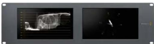
SmartView Duo SmartScope Duo 4K
Collegare le fonti video

InstallSmartView 5.0

Uninstall SmartView
Blackmagicdesign

Allow Utility Administration
Announce Interval and Timeout
SmartView e SmartScope Duo 4K
Brightness, Contrast Saturation
Developer Information (English)
Blackmagic 2K Format - Overview
Blackmagic Design products support 3G-SDI video, which allows twice the data rate of traditional HD-SDI video. We thought it would be a really nice idea to add 2K film support, via 3G-SDI technology, so we could simplify feature film workflows. With the popularity of Blackmagic Design editing systems worldwide, now thousands of people can benefit from a feature film workflow revolution.
This information includes everything product developers need to know for building native 2K SDI equipment. Of course, all Blackmagic products can be updated, so if the television industry adopts an alternative SDI-based film standard, we can add support for that too!
Frame Structure
- Transmitted at 23.98, 24 or 25 frames per second as a Progressive Segmented Frame.
Active video is 2048 pixels wide by 1556 lines deep.
Total lines per frame : 1650 - Active words per line are 1535. One word consists of a 10-bit sample for each of the four data streams, i.e., a total of 40 bits. See the diagram named Blackmagic 2K Format - Data Stream Format.
Total active lines : 1556
Total words per line: 1875 for 23.98/24Hz and 1800 for 25Hz.
Fields per frame: 2, 825 lines each
Active lines located on lines 16-793 (field 1) and 841-1618 (field 2).
Transport Structure
- Based on SMPTE 372M Dual Link mapping and SMPTE 425M-B support for mapping SMPTE 372M into a single 3 Gb/s link.
- Timing reference signals, line number and line CRC insertion is the same as above.
- During active video, 10-bit Red, Green and Blue data is sent in the following sequence:
- Optional ancillary data is inserted into both virtual interfaces.
-
At present, only audio data is included: as per standard HD audio insertion (SMPTE S299M) the audio data packets are carried on data stream two and audio control packets are carried on data stream one.
-
Data stream 1: Green_1, Green_2, Green_3, Green_5...Green_2047
- Data stream 2: Blue_1, Blue_2, Green_4, Blue_5...Green_2048.
- Data stream 3: Red_1, Blue_3, Blue_4, Red_5...Blue_2048.
Data stream 4: Red_2, Red_3, Red_4, Red_6...Red_2048.
Blackmagic 2K Format - Vertical Timing Reference
This diagram shows the vertical timing details with line numbers and Field, Vertical and Horizontal bits for the Timing Reference Signal codes.
| Field 1 Active | ||||||||||||
| F1000 | 0000 | 000 | ||||||||||
| V11111 | 0000 | 11 | ||||||||||
| LINE # | 1650 | 1 | 2 | ... | 14 | 15 | 16 | ... | 792 | 793 | ... | 825 |
| Field 2 Active | ||||||||||||
| F | 0 | 1 | 1 | 1 | 1 | 1 | 1 | 1 | 1 | 1 | 1 | 1 |
| V | 1 | 1 | 1 | 1 | 1 | 1 | 0 | 0 | 0 | 0 | 1 | 1 |
| LINE # | 825 | 826 | 827 | ... | 839 | 840 | 841 | ... | 1617 | 1618 | ... | 1650 |
Blackmagic 2K Format - Data Stream Format
This diagram shows the data stream formats around the optional ancillary data section of the horizontal line. Note that each active pixel takes up three samples.
| Word#25 PsF | Word#23.98/24 PsF | Data Stream 4 | Data Stream 3 | Data Stream 2 | Data Stream 1 |
| 1795 | 1870 | R2042 | R2041 | B2041 | G2041 |
| 1796 | 1871 | R2043 | B2043 | B2042 | G2042 |
| 1797 | 1872 | R2044 | B2044 | G2044 | G2043 |
| 1798 | 1873 | R2046 | R2045 | B2045 | G2045 |
| 1799 | 1874 | R2047 | B2047 | B2046 | G2046 |
| 1800 | 1875 | R2048 | B2048 | G2048 | G2047 |
| 1 | 1 | EAV(3FFh) | EAV(3FFh) | EAV(3FFh) | EAV(3FFh) |
| 2 | 2 | EAV(000h) | EAV(000h) | EAV(000h) | EAV(000h) |
| 3 | 3 | EAV(000h) | EAV(000h) | EAV(000h) | EAV(000h) |
| 4 | 4 | EAV(XYZh) | EAV(XYZh) | EAV(XYZh) | EAV(XYZh) |
| 5 | 5 | LNO | LNO | LNO | LNO |
| 6 | 6 | LN1 | LN1 | LN1 | LN1 |
| 7 | 7 | CRCO | CRCO | CRCO | CRCO |
| 8 | 8 | CRC1 | CRC1 | CRC1 | CRC1 |
| 9 | 9 | 200 | 040 | ANC/Audio Data | ANC/Audio Data |
| ... | ... | ... | ... | ||
| 260 | 335 | 200 | 040 | ||
| 261 | 336 | SAV(3FFh) | SAV(3FFh) | SAV(3FFh) | SAV(3FFh) |
| 262 | 337 | SAV(000h) | SAV(000h) | SAV(000h) | SAV(000h) |
| 263 | 338 | SAV(000h) | SAV(000h) | SAV(000h) | SAV(000h) |
| 264 | 339 | SAV(XYZh) | SAV(XYZh) | SAV(XYZh) | SAV(XYZh) |
| 265 | 340 | R2 | R1 | B1 | G1 |
| 266 | 341 | R3 | B3 | B2 | G2 |
| 267 | 342 | R4 | B4 | G4 | G3 |
| 268 | 343 | R6 | R5 | B5 | G5 |
Blackmagic SmartView Ethernet Protocol v1.4
Summary
The Blackmagic SmartView Ethernet Protocol is a text-based status and control protocol, very similar in structure to the Videohub protocol, that is accessed by connecting to TCP port 9992 on a SmartView or SmartScope monitor.
Upon connection, the SmartView or SmartScope monitor sends a complete dump of the state of the monitor. After the initial dump, state changes are sent asynchronously.
The SmartView or SmartScope sends information in blocks which have an identifying header, followed by a colon. A block can span multiple lines and is terminated by a blank line.
To be resilient to future protocol changes, clients should ignore blocks they do not recognize, up to the trailing blank line. Within recognized blocks, clients should ignore lines they do not recognize.
Legend
carriage return
and so on
Version 1.4 of the Blackmagic SmartView Ethernet
Protocol was released with SmartView 1.4 software.
Protocol Preamble
The first block sent by the SmartView Server is always the protocol preamble:
PROTOCOL PREAMBLE:
Version: 1.4
The version field indicates the protocol version. When the protocol is changed in a compatible way, the minor version number will be updated. If incompatible changes are made, the major version number will be updated.
Device Information
The next block contains general information about the connected SmartView or SmartScope.
SMARTVIEW DEVICE:←
Model:SmartView Duo
Hostname: stagefront studio.example.com
Name:StageFront
Monitors: 2
Inverted: false
This example shows the output for a SmartView Duo, which has two LCDs.
The INVERTED flag indicates whether the monitor has detected that it has been mounted in an inverted configuration to optimize LCD viewing angle.
Network Configuration
The next block shows the TCP/IP networking configuration:
NETWORK:
Dynamic IP: true
Static address: 192.168.2.2
Static n etm ask: 255.255.255.0
St atic g atew ay: 192.168.241
C u r rent add r ess: 192.168.1.101
C u r rent n etm ask: 255.255.265.0
C u r rent gate w ay: 192.168.1.1
The network settings prefixed with CURRENT show the active TCP/IP settings, and are readily. The CURRENT settings reflect either the DHCP or Static configuration, depending on the DYNAMIC IP flag.
Changing Networking Settings
The network can be configured to use either DHCP or a static configuration. To enable DHCP:
NETWORK:
Dynamic IP: true
←
To set a fixed IP address, supply all static parameters, thus:
NETWORK:
Dynamic IP: false
Static address: 192.168.2.2
Static n etm ask: 255.255.255.e1
St atic g atew ay: 192.168.241
The parameters with the CURRENT prefix are read-only, and show the active configuration, regardless of the static or dynamic setting.
Changing the name, or any network settings, will cause the IP connection to be dropped. The SmartView or SmartScope will restart its networking and advertise its new name on the network.
Changing Monitor Settings
The display settings for each monitor are specified individually. One or more parameters can be modified at the same time and multiple settings can be supplied in one block.
The valid range for numeric values is 0-255. The CONTRAST and SATURATION properties are zero-centered, so the normal value is 127, such that the displayed picture is the same as the original. A value greater than 127 in either channel will cause the contrast or saturation to be increased, and similarly a value less than 127 will cause a decrease.
For example, to set the brightness to 50% and desaturate the image to Black & White:
MONITOR A: Brightness: 127 Saturation: 0
Displaying SD in 16:9
The following command sets standard definition video to display in 16:9:
MONITOR A:
WidescreenSD:ON
Displaying SD in 4:3
The following command sets standard definition video to display in 4:3:
MONITOR A:
WidescreenSD: OFF
Identification and Tally Settings
The Identify flag is transient, and will cause a white border to be displayed around the entire picture for a duration of 15 seconds, after which it will be reset. This feature is primarily aimed at identifying which monitor is currently being configured when it is mounted in a rack comprising multiple units. To turn on:
MONITOR A:
Identify: trale
The IDENTIFY border will temporarily override any other border setting in effect.
The BORDER property can be used to programmatically set the soft Tally colored borders to one of the primary colors: RED, GREEN, BLUE, WHITE or NONE. This setting can be overridden by the electrical Tally signals at the DB-9 input on the monitor itself. For example, to set the soft Tally to green:
MONITOR B:
Border:green
The hard wired tally will always override the soft tally. The full state report will always show the current valid border.
SmartScope Settings
On SmartScope Duo 4K, each monitor can be set to display a different scope. The values for activating specific scopes are mapped as follows:
AudioDbfs
AudioDbvu
Histogram
ParadeRGB
ParadeYUV
Picture (This is the same as Video Monitor)
Vector100
Vector75
WaveformLuma
MONITOR A:
ScopeMode: Picture
In the example above, Monitor A has been set as a video monitor.
Displaying SD in 16:9
The set Video Monitor mode to display standard definition video in 16:9:
MOTOR A:ScopeMode:Picture WidescreenSD:ON
Displaying SD in 4:3
To set Video Monitor mode to display standard definition video in 4:3:
MOTOR A:ScopeMode:Picture WidescreenSD:OFF
When setting one of SmartScope Duo 4K's monitors to audio metering, you can also select which channels to show. The values for selecting which audio channels are mapped in the following way:
0: Channels 1 and 2
1: Channels 3 and 4
2: Channels 5 and 6
3: Channels 7 and 8
4: Channels 9 and 10
5: Channels 11 and 12
6: Channels 13 and 14
7: Channels 15 and 16
MONITOR B:ScopeMode:AudioDbvu AudioChannel:0
In the example above, Monitor B has been selected to display Audio Metering in Dbvu with audio channels 1 and 2 selected for the phase meter.
Selecting LUTs for SmartView 4K
To select 3D LUTs using SmartView 4K:
MONITOR A: LUT: 0 LUT 1 LUT 2 NONE DISABLE
Assistenza
Assistenza clienti
3G-SDI:PL-4F20-311C
- 6G-SDI: PL-8F10-311C
12G-SDI:PL-TG10-311C

SmartView SmartScope


Prezado cliente,
SmartView e SmartScope Duo 4K 416
Enable Tally Override 418
Usar SmartScope Duo 4K 418
Vertical Timing Reference 433
Blackmagic 2K Format - Data
Stream Format 433
Blackmagic SmartView
Ethernet Protocol v1.4 434
Ajuda 438
Informacoes Regulatoras 439
Informacoes de Seguranca 440
Garantia 441
Primeiros Passos
Apresentando SmartView e SmartScope
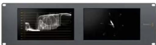
SmartView Duo SmartScope Duo 4K
Conectar Fontes de Video

InstallSmartView 5.0

Uninstall SmartView
Blackmagickdesign

Allow Utility Administration
Announce Interval and Timeout
SmartView e SmartScope Duo 4K
Brightness, Contrast Saturation
Enable Tally Override
Usar SmartScope Duo 4K
"Display" do Blackmagic SmartView Setup.
Exibicao de Historama
Blackmagic Design products support 3G-SDI video, which allows twice the data rate of traditional HD-SDI video. We thought it would be a really nice idea to add 2K film support, via 3G-SDI technology, so we could simplify feature film workflows. With the popularity of Blackmagic Design editing systems worldwide, now thousands of people can benefit from a feature film workflow revolution.
This information includes everything product developers need to know for building native 2K SDI equipment. Of course, all Blackmagic products can be updated, so if the television industry adopts an alternative SDI-based film standard, we can add support for that too!
Frame Structure
- Transmitted at 23.98, 24 or 25 frames per second as a Progressive Segmented Frame.
Active video is 2048 pixels wide by 1556 lines deep.
Total lines per frame : 1650 - Active words per line are 1535. One word consists of a 10-bit sample for each of the four data streams, i.e., a total of 40 bits. See the diagram named Blackmagic 2K Format - Data Stream Format.
Total active lines : 1556
Total words per line: 1875 for 23.98/24Hz and 1800 for 25Hz.
Fields per frame: 2, 825 lines each
Active lines located on lines 16-793 (field 1) and 841-1618 (field 2).
Transport Structure
- Based on SMPTE 372M Dual Link mapping and SMPTE 425M-B support for mapping SMPTE 372M into a single 3 Gb/s link.
- Timing reference signals, line number and line CRC insertion is the same as above.
- During active video, 10-bit Red, Green and Blue data is sent in the following sequence:
- Optional ancillary data is inserted into both virtual interfaces.
-
At present, only audio data is included: as per standard HD audio insertion (SMPTE S299M) the audio data packets are carried on data stream two and audio control packets are carried on data stream one.
-
Data stream 1: Green_1, Green_2, Green_3, Green_5...Green_2047
- Data stream 2: Blue_1, Blue_2, Green_4, Blue_5...Green_2048.
- Data stream 3: Red_1, Blue_3, Blue_4, Red_5...Blue_2048.
Data stream 4: Red_2, Red_3, Red_4, Red_6...Red_2048.
Blackmagic 2K Format - Vertical Timing Reference
This diagram shows the vertical timing details with line numbers and Field, Vertical and Horizontal bits for the Timing Reference Signal codes.
| Field 1 Active | ||||||||||||
| F1000 | 0000 | 000 | ||||||||||
| V11111 | 0000 | 11 | ||||||||||
| LINE # | 1650 | 1 | 2 | ... | 14 | 15 | 16 | ... | 792 | 793 | ... | 825 |
| Field 2 Active | ||||||||||||
| F | 0 | 1 | 1 | 1 | 1 | 1 | 1 | 1 | 1 | 1 | 1 | 1 |
| V | 1 | 1 | 1 | 1 | 1 | 1 | 0 | 0 | 0 | 0 | 1 | 1 |
| LINE # | 825 | 826 | 827 | ... | 839 | 840 | 841 | ... | 1617 | 1618 | ... | 1650 |
Blackmagic 2K Format - Data Stream Format
This diagram shows the data stream formats around the optional ancillary data section of the horizontal line. Note that each active pixel takes up three samples.
| Word#25 PsF | Word#23.98/24 PsF | Data Stream 4 | Data Stream 3 | Data Stream 2 | Data Stream 1 |
| 1795 | 1870 | R2042 | R2041 | B2041 | G2041 |
| 1796 | 1871 | R2043 | B2043 | B2042 | G2042 |
| 1797 | 1872 | R2044 | B2044 | G2044 | G2043 |
| 1798 | 1873 | R2046 | R2045 | B2045 | G2045 |
| 1799 | 1874 | R2047 | B2047 | B2046 | G2046 |
| 1800 | 1875 | R2048 | B2048 | G2048 | G2047 |
| 1 | 1 | EAV(3FFh) | EAV(3FFh) | EAV(3FFh) | EAV(3FFh) |
| 2 | 2 | EAV(000h) | EAV(000h) | EAV(000h) | EAV(000h) |
| 3 | 3 | EAV(000h) | EAV(000h) | EAV(000h) | EAV(000h) |
| 4 | 4 | EAV(XYZh) | EAV(XYZh) | EAV(XYZh) | EAV(XYZh) |
| 5 | 5 | LNO | LNO | LNO | LNO |
| 6 | 6 | LN1 | LN1 | LN1 | LN1 |
| 7 | 7 | CRCO | CRCO | CRCO | CRCO |
| 8 | 8 | CRC1 | CRC1 | CRC1 | CRC1 |
| 9 | 9 | 200 | 040 | ANC/Audio Data | ANC/Audio Data |
| ... | ... | ... | ... | ||
| 260 | 335 | 200 | 040 | ||
| 261 | 336 | SAV(3FFh) | SAV(3FFh) | SAV(3FFh) | SAV(3FFh) |
| 262 | 337 | SAV(000h) | SAV(000h) | SAV(000h) | SAV(000h) |
| 263 | 338 | SAV(000h) | SAV(000h) | SAV(000h) | SAV(000h) |
| 264 | 339 | SAV(XYZh) | SAV(XYZh) | SAV(XYZh) | SAV(XYZh) |
| 265 | 340 | R2 | R1 | B1 | G1 |
| 266 | 341 | R3 | B3 | B2 | G2 |
| 267 | 342 | R4 | B4 | G4 | G3 |
| 268 | 343 | R6 | R5 | B5 | G5 |
Blackmagic SmartView Ethernet Protocol v1.4
Summary
The Blackmagic SmartView Ethernet Protocol is a text-based status and control protocol, very similar in structure to the Videohub protocol, that is accessed by connecting to TCP port 9992 on a SmartView or SmartScope monitor.
Upon connection, the SmartView or SmartScope monitor sends a complete dump of the state of the monitor. After the initial dump, state changes are sent asynchronously.
The SmartView or SmartScope sends information in blocks which have an identifying header, followed by a colon. A block can span multiple lines and is terminated by a blank line.
To be resilient to future protocol changes, clients should ignore blocks they do not recognize, up to the trailing blank line. Within recognized blocks, clients should ignore lines they do not recognize.
Legend
carriage return
and so on
Version 1.4 of the Blackmagic SmartView Ethernet
Protocol was released with SmartView 1.4 software.
Protocol Preamble
The first block sent by the SmartView Server is always the protocol preamble:
PROTOCOL PREAMBLE:
Version: 1.4
The version field indicates the protocol version. When the protocol is changed in a compatible way, the minor version number will be updated. If incompatible changes are made, the major version number will be updated.
Device Information
The next block contains general information about the connected SmartView or SmartScope.
SMARTVIEW DEVICE:←
Model:SmartView Duo
Hostname: stagefront studio.example.com
Name:StageFront
Monitors: 2
Inverted: false
This example shows the output for a SmartView Duo, which has two LCDs.
The INVERTED flag indicates whether the monitor has detected that it has been mounted in an inverted configuration to optimize LCD viewing angle.
Network Configuration
The next block shows the TCP/IP networking configuration:
NETWORK:
Dynamic IP: true
Static address: 192.168.2.0
Static n etm ask: 255.255.255.0
St atic g atew ay: 192.168.241
C u r rent add r ess: 192.168.1-101
C u r rent n etm ask: 255.255.255.0
C u r rent gate w ay: 192.168.4.1
The network settings prefixed with CURRENT show the active TCP/IP settings, and are readily. The CURRENT settings reflect either the DHCP or Static configuration, depending on the DYNAMIC IP flag.
Changing Networking Settings
The network can be configured to use either DHCP or a static configuration. To enable DHCP:
NETWORK:
Dynamic IP: true
←
To set a fixed IP address, supply all static parameters, thus:
NETWORK:
Dynamic IP: false
Static address: 192.168.2.2
Static netm ask: 255.255.255.0
St atic g atew ay: 192.168.2.1
The parameters with the CURRENT prefix are read-only, and show the active configuration, regardless of the static or dynamic setting.
Changing the name, or any network settings, will cause the IP connection to be dropped. The SmartView or SmartScope will restart its networking and advertise its new name on the network.
Changing Monitor Settings
The display settings for each monitor are specified individually. One or more parameters can be modified at the same time and multiple settings can be supplied in one block.
The valid range for numeric values is 0-255. The CONTRAST and SATURATION properties are zero-centered, so the normal value is 127, such that the displayed picture is the same as the original. A value greater than 127 in either channel will cause the contrast or saturation to be increased, and similarly a value less than 127 will cause a decrease.
For example, to set the brightness to 50% and desaturate the image to Black & White:
MONITOR A: Brightness: 127 Saturation: 0
Displaying SD in 16:9
The following command sets standard definition video to display in 16:9:
MONITOR A:
WidescreenSD:ON
Displaying SD in 4:3
The following command sets standard definition video to display in 4:3:
MONITOR A:
WidescreenSD: OFF
Identification and Tally Settings
The Identify flag is transient, and will cause a white border to be displayed around the entire picture for a duration of 15 seconds, after which it will be reset. This feature is primarily aimed at identifying which monitor is currently being configured when it is mounted in a rack comprising multiple units. To turn on:
MONITOR A:
Identify: trale
The IDENTIFY border will temporarily override any other border setting in effect.
The BORDER property can be used to programmatically set the soft Tally colored borders to one of the primary colors: RED, GREEN, BLUE, WHITE or NONE. This setting can be overridden by the electrical Tally signals at the DB-9 input on the monitor itself. For example, to set the soft Tally to green:
MONITOR B:
Border:green
The hard wired tally will always override the soft tally. The full state report will always show the current valid border.
SmartScope Settings
On SmartScope Duo 4K, each monitor can be set to display a different scope. The values for activating specific scopes are mapped as follows:
AudioDbfs
AudioDbvu
Histogram
ParadeRGB
ParadeYUV
Picture (This is the same as Video Monitor)
Vector100
Vector75
WaveformLuma
MONITOR A:
ScopeMode: Picture
In the example above, Monitor A has been set as a video monitor.
Displaying SD in 16:9
The set Video Monitor mode to display standard definition video in 16:9:
MOTOR A:ScopeMode:Picture WidescreenSD:ON
Displaying SD in 4:3
To set Video Monitor mode to display standard definition video in 4:3:
MOTOR A:ScopeMode:Picture WidescreenSD:OFF
When setting one of SmartScope Duo 4K's monitors to audio metering, you can also select which channels to show. The values for selecting which audio channels are mapped in the following way:
0: Channels 1 and 2
1: Channels 3 and 4
2: Channels 5 and 6
3: Channels 7 and 8
4: Channels 9 and 10
5: Channels 11 and 12
6: Channels 13 and 14
7: Channels 15 and 16
MONITOR B:ScopeMode:AudioDbvu AudioChannel:0
In the example above, Monitor B has been selected to display Audio Metering in Dbvu with audio channels 1 and 2 selected for the phase meter.
Selecting LUTs for SmartView 4K
To select 3D LUTs using SmartView 4K:
MONITOR A: LUT: 0 LUT 1 LUT 2 NONE DISABLE
Ajuda
Obter Ajuda
SmartView SmartScope


Hoş Geldiniz!
CEO Blackmagic Design
icindekiler
Baslarken
SmartView ve SmartScope ile Tanisin 445
Video Kaynaklarinin Takilmasi 446
SmartView ve SmartScope Duo 4K 460
Monitor Ayarlinin Degistirilmesi 460
Tally Onceliigi Etkinlestirme 462
SmartScope Duo 4K Kullanimi 462
Blackmagic SmartScope Ndir? 462
VideoGoruntulemeEkrani 463
Waveform (Dalga Sekli) Ekrani 464
Vektorskop Ekram45 465
Parade Ekrani 466
Histogram Ekrani 468
SesGöstergeEkrani 469
Aγ Ayarlari 470
Bir Aga Baqlanirken 471
Dogrudan Ethernet Baglantisi 471
Ethernet A# Da#itici 472
Tally Ozelliginin Kullanilmasi 473
Tally Port Pin Baglantilari 473
Izlemc AcsinIn Optimize Edilmesi 474
Developer Information 476
Blackmagic 2K Format-Overview 476
Blackmagic 2K Format -
Vertical Timing Reference 477
Blackmagic 2K Format - Data
Stream Format 477
Blackmagic SmartView
Ethernet Protocol v1.4 478
Yardim 482
Mevzuata lliskin Bildirimler 483

SmartView Duo SmartScope Duo 4K
Video Kaynaklarinin Takilmasi
Allow Utility Administration (Yardimci Yazilm Yonetimine Izin Ver)
SmartView ve SmartScope Duo 4K
Blackmagic Design products support 3G-SDI video, which allows twice the data rate of traditional HD-SDI video. We thought it would be a really nice idea to add 2K film support, via 3G-SDI technology, so we could simplify feature film workflows. With the popularity of Blackmagic Design editing systems worldwide, now thousands of people can benefit from a feature film workflow revolution.
This information includes everything product developers need to know for building native 2K SDI equipment. Of course, all Blackmagic products can be updated, so if the television industry adopts an alternative SDI-based film standard, we can add support for that too!
Frame Structure
- Transmitted at 23.98, 24 or 25 frames per second as a Progressive Segmented Frame.
Active video is 2048 pixels wide by 1556 lines deep.
Total lines per frame : 1650 - Active words per line are 1535. One word consists of a 10-bit sample for each of the four data streams, i.e., a total of 40 bits. See the diagram named Blackmagic 2K Format - Data Stream Format.
Total active lines: 1556
Total words per line: 1875 for 23.98/24Hz and 1800 for 25Hz.
Fields per frame: 2, 825 lines each
Active lines located on lines 16-793 (field 1) and 841-1618 (field 2).
Transport Structure
- Based on SMPTE 372M Dual Link mapping and SMPTE 425M-B support for mapping SMPTE 372M into a single 3 Gb/s link.
- Timing reference signals, line number and line CRC insertion is the same as above.
- During active video, 10-bit Red, Green and Blue data is sent in the following sequence:
- Optional ancillary data is inserted into both virtual interfaces.
-
At present, only audio data is included: as per standard HD audio insertion (SMPTE S299M) the audio data packets are carried on data stream two and audio control packets are carried on data stream one.
-
Data stream 1: Green_1, Green_2, Green_3, Green_5...Green_2047
- Data stream 2: Blue_1, Blue_2, Green_4, Blue_5...Green_2048.
- Data stream 3: Red_1, Blue_3, Blue_4, Red_5...Blue_2048.
Data stream 4: Red_2, Red_3, Red_4, Red_6...Red_2048.
Blackmagic 2K Format - Vertical Timing Reference
This diagram shows the vertical timing details with line numbers and Field, Vertical and Horizontal bits for the Timing Reference Signal codes.
| Field 1 Active | ||||||||||||
| F1000 | 0000 | 000 | ||||||||||
| V11111 | 0000 | 11 | ||||||||||
| LINE # | 1650 | 1 | 2 | ... | 14 | 15 | 16 | ... | 792 | 793 | ... | 825 |
| Field 2 Active | ||||||||||||
| F | 0 | 1 | 1 | 1 | 1 | 1 | 1 | 1 | 1 | 1 | 1 | 1 |
| V | 1 | 1 | 1 | 1 | 1 | 1 | 0 | 0 | 0 | 0 | 1 | 1 |
| LINE # | 825 | 826 | 827 | ... | 839 | 840 | 841 | ... | 1617 | 1618 | ... | 1650 |
Blackmagic 2K Format - Data Stream Format
This diagram shows the data stream formats around the optional ancillary data section of the horizontal line. Note that each active pixel takes up three samples.
| Word#25 PsF | Word#23.98/24 PsF | Data Stream 4 | Data Stream 3 | Data Stream 2 | Data Stream 1 |
| 1795 | 1870 | R2042 | R2041 | B2041 | G2041 |
| 1796 | 1871 | R2043 | B2043 | B2042 | G2042 |
| 1797 | 1872 | R2044 | B2044 | G2044 | G2043 |
| 1798 | 1873 | R2046 | R2045 | B2045 | G2045 |
| 1799 | 1874 | R2047 | B2047 | B2046 | G2046 |
| 1800 | 1875 | R2048 | B2048 | G2048 | G2047 |
| 1 | 1 | EAV(3FFh) | EAV(3FFh) | EAV(3FFh) | EAV(3FFh) |
| 2 | 2 | EAV(000h) | EAV(000h) | EAV(000h) | EAV(000h) |
| 3 | 3 | EAV(000h) | EAV(000h) | EAV(000h) | EAV(000h) |
| 4 | 4 | EAV(XYZh) | EAV(XYZh) | EAV(XYZh) | EAV(XYZh) |
| 5 | 5 | LNO | LNO | LNO | LNO |
| 6 | 6 | LN1 | LN1 | LN1 | LN1 |
| 7 | 7 | CRCO | CRCO | CRCO | CRCO |
| 8 | 8 | CRC1 | CRC1 | CRC1 | CRC1 |
| 9 | 9 | 200 | 040 | ANC/Audio Data | ANC/Audio Data |
| ... | ... | ... | ... | ||
| 260 | 335 | 200 | 040 | ||
| 261 | 336 | SAV(3FFh) | SAV(3FFh) | SAV(3FFh) | SAV(3FFh) |
| 262 | 337 | SAV(000h) | SAV(000h) | SAV(000h) | SAV(000h) |
| 263 | 338 | SAV(000h) | SAV(000h) | SAV(000h) | SAV(000h) |
| 264 | 339 | SAV(XYZh) | SAV(XYZh) | SAV(XYZh) | SAV(XYZh) |
| 265 | 340 | R2 | R1 | B1 | G1 |
| 266 | 341 | R3 | B3 | B2 | G2 |
| 267 | 342 | R4 | B4 | G4 | G3 |
| 268 | 343 | R6 | R5 | B5 | G5 |
Blackmagic SmartView Ethernet Protocol v1.4
Summary
The Blackmagic SmartView Ethernet Protocol is a text-based status and control protocol, very similar in structure to the Videohub protocol, that is accessed by connecting to TCP port 9992 on a SmartView or SmartScope monitor.
Upon connection, the SmartView or SmartScope monitor sends a complete dump of the state of the monitor. After the initial dump, state changes are sent asynchronously.
The SmartView or SmartScope sends information in blocks which have an identifying header, followed by a colon. A block can span multiple lines and is terminated by a blank line.
To be resilient to future protocol changes, clients should ignore blocks they do not recognize, up to the trailing blank line. Within recognized blocks, clients should ignore lines they do not recognize.
Legend
carriage return
and so on
Version 1.4 of the Blackmagic SmartView Ethernet
Protocol was released with SmartView 1.4 software.
Protocol Preamble
The first block sent by the SmartView Server is always the protocol preamble:
PROTOCOL PREAMBLE:
Version: 1.4
The version field indicates the protocol version. When the protocol is changed in a compatible way, the minor version number will be updated. If incompatible changes are made, the major version number will be updated.
Device Information
The next block contains general information about the connected SmartView or SmartScope.
SMARTVIEW DEVICE:←
Model:SmartView Duo
Hostname: stagefront studio.example.com
Name:StageFront
Monitors: 2
Inverted: false
This example shows the output for a SmartView Duo, which has two LCDs.
The INVERTED flag indicates whether the monitor has detected that it has been mounted in an inverted configuration to optimize LCD viewing angle.
Network Configuration
The next block shows the TCP/IP networking configuration:
NETWORK:
Dynamic IP: true
Static address: 192.168.2.0
Static n etm ask: 255.255.255.0
St atic g atew ay: 192.168.241
C u r rent add r ess: 192.168.1-101
C u r rent n etm ask: 255.255.255.0
C u r rent gate w ay: 192.168.4.1
The network settings prefixed with CURRENT show the active TCP/IP settings, and are readily. The CURRENT settings reflect either the DHCP or Static configuration, depending on the DYNAMIC IP flag.
Changing Networking Settings
The network can be configured to use either DHCP or a static configuration. To enable DHCP:
NETWORK:
Dynamic IP: true
←
To set a fixed IP address, supply all static parameters, thus:
NETWORK:
Dynamic IP: false
Static address: 192.168.2.2
Static netm ask: 255.255.255.0
St atic g atew ay: 192.168.2.1
The parameters with the CURRENT prefix are read-only, and show the active configuration, regardless of the static or dynamic setting.
Changing the name, or any network settings, will cause the IP connection to be dropped. The SmartView or SmartScope will restart its networking and advertise its new name on the network.
Changing Monitor Settings
The display settings for each monitor are specified individually. One or more parameters can be modified at the same time and multiple settings can be supplied in one block.
The valid range for numeric values is 0-255. The CONTRAST and SATURATION properties are zero-centered, so the normal value is 127, such that the displayed picture is the same as the original. A value greater than 127 in either channel will cause the contrast or saturation to be increased, and similarly a value less than 127 will cause a decrease.
For example, to set the brightness to 50% and desaturate the image to Black & White:
MONITOR A: Brightness: 127 Saturation: 0
Displaying SD in 16:9
The following command sets standard definition video to display in 16:9:
MONITOR A:
WidescreenSD:ON
Displaying SD in 4:3
The following command sets standard definition video to display in 4:3:
MONITOR A:
WidescreenSD: OFF
Identification and Tally Settings
The Identify flag is transient, and will cause a white border to be displayed around the entire picture for a duration of 15 seconds, after which it will be reset. This feature is primarily aimed at identifying which monitor is currently being configured when it is mounted in a rack comprising multiple units. To turn on:
MONITOR A:
Identify: trale
The IDENTIFY border will temporarily override any other border setting in effect.
The BORDER property can be used to programmatically set the soft Tally colored borders to one of the primary colors: RED, GREEN, BLUE, WHITE or NONE. This setting can be overridden by the electrical Tally signals at the DB-9 input on the monitor itself. For example, to set the soft Tally to green:
MONITOR B:
Border:green
The hard wired tally will always override the soft tally. The full state report will always show the current valid border.
SmartScope Settings
On SmartScope Duo 4K, each monitor can be set to display a different scope. The values for activating specific scopes are mapped as follows:
AudioDbfs
AudioDbvu
Histogram
ParadeRGB
ParadeYUV
Picture (This is the same as Video Monitor)
Vector100
Vector75
WaveformLuma
MONITOR A:
ScopeMode: Picture
In the example above, Monitor A has been set as a video monitor.
Displaying SD in 16:9
The set Video Monitor mode to display standard definition video in 16:9:
MOTOR A:ScopeMode:Picture WidescreenSD:ON
Displaying SD in 4:3
To set Video Monitor mode to display standard definition video in 4:3:
MOTOR A:ScopeMode:Picture WidescreenSD:OFF
When setting one of SmartScope Duo 4K's monitors to audio metering, you can also select which channels to show. The values for selecting which audio channels are mapped in the following way:
0: Channels 1 and 2
1: Channels 3 and 4
2: Channels 5 and 6
3: Channels 7 and 8
4: Channels 9 and 10
5: Channels 11 and 12
6: Channels 13 and 14
7: Channels 15 and 16
MONITOR B:ScopeMode:AudioDbvu AudioChannel:0
In the example above, Monitor B has been selected to display Audio Metering in Dbvu with audio channels 1 and 2 selected for the phase meter.
Selecting LUTs for SmartView 4K
To select 3D LUTs using SmartView 4K:
MONITOR A: LUT: 0 LUT 1 LUT 2 NONE DISABLE
Yardim
Yardim İçın
Yardim almak icin takip edeceginiz dort adim vardir.
-3G-SDI:PL-4F20-311C
-6G-SDI:PL-8F10-311C
-12G-SDI:PL-TG10-311C