
LB 553iV - Electric mower HUSQVARNA - Free user manual and instructions
Find the device manual for free LB 553iV HUSQVARNA in PDF.
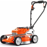




| Product type | Electric push mower |
| Model | LB 553iV |
| Brand | Husqvarna |
| Weight without battery | 38 kg |
| Battery type | Husqvarna 36 V lithium-ion |
| Recommended battery | BLi20, BLi200, BLi300, BLi550X, BLi950X |
| Cutting width | 53 cm |
| Cutting height | 28-65 mm (5 levels) |
| Motor type | BLDC (brushless) 36 V |
| Motor speed (nominal) | 3,000 rpm |
| Motor speed (SavE) | 2,600 rpm |
| Max motor power | 1.8 kW |
| Drive motor | Yes, 0.4 kW, adjustable speed 3.0-5.0 km/h (4 levels) |
| SavE function (battery saving) | Yes |
| Automatic PowerBoost | Yes |
| Battery runtime (9.4 Ah) | 35 min (SavE), 30 min (standard) |
| Guaranteed sound power level | 98 dB(A) |
| Sound pressure level at user | 84 dB(A) |
| Handle vibrations | 1.3 m/s² |
| BioClip system | Yes (mulching) |
| Safety devices | Motor brake handle, anti-start, safety key, cutting deck cover |
| Battery protection | IPX4 (splash water) |
| Compatible charger | QC80, QC80F, QC330, QC500 |
| Blade maintenance | Sharpening and balancing by approved center |
| Warranty | See declaration of conformity |
Frequently Asked Questions - LB 553iV HUSQVARNA
User questions about LB 553iV HUSQVARNA
0 question about this device. Answer the ones you know or ask your own.
Ask a new question about this device
Download the instructions for your Electric mower in PDF format for free! Find your manual LB 553iV - HUSQVARNA and take your electronic device back in hand. On this page are published all the documents necessary for the use of your device. LB 553iV by HUSQVARNA.
USER MANUAL LB 553iV HUSQVARNA
LB 548i, LC 551iV, LB 553iV
EAC

EN Operator's manual 2-33
Transportation, storage and disposal.... 28
Technical data.... 29
Declaration of Conformity.... 32
Introduction
Product description
The product is a pedestrian-controlled rotary lawn mower. The models LB 548i and LB 553iV use BioClip to cut the grass into fertilizer.
The model LC 551iV collects the grass in a grass catcher. Remove the grass catcher to get rear discharge
of the grass. Attach a mulch kit (accessory) to cut the grass into fertilizer.
Intended use
Use the product to cut grass. Do not use the product for other tasks.
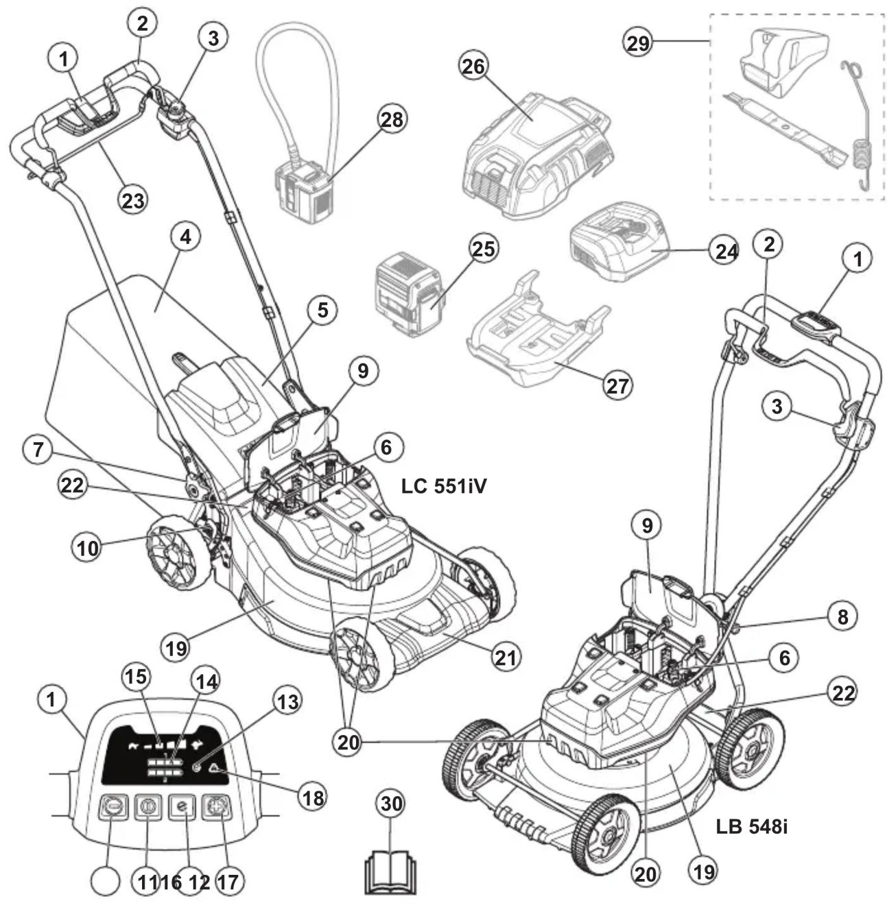
- Control panel
- Motor brake handle
- Start inhibitor
- Grass catcher (LC 551iV)
- Rear cover (LC 551iV)
- Safety key
- Handle knob (LC 551iV)
- Handle adjustment lever (LB 548i)
- Battery cover
- Cutting height control (LC 551iV)
- ON/OFF button
- SavE button
- SavE indicator
- Battery indicator
- Speed level indicator
- Decrease speed button
- Increase speed button
- Error LED
- Cutting cover
- Air intakes
- Protection cover (LC 551iV)
- Rating plate
- Drive bail (LC 551iV)
- Battery charger (Accessory)
- Battery (Accessory)
- Multi battery (Accessory)
- Adapter plate (Accessory)
- Multi battery adapter (Accessory)
- Mulch kit (LC 551iV)
- Operator's manual
Product overview (LB 553iV)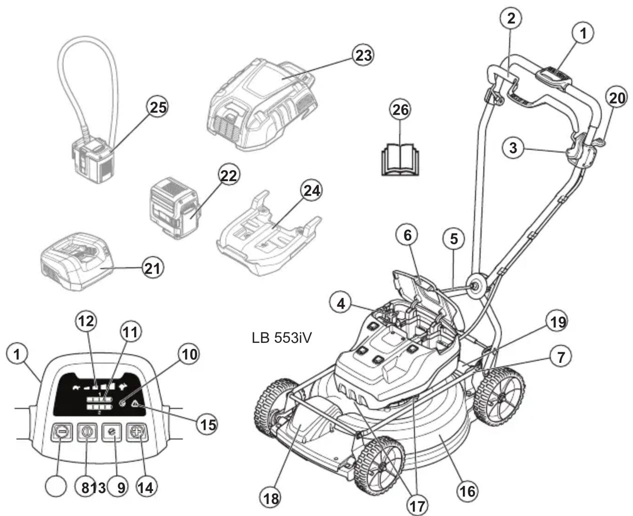
- Control panel
- Motor brake handle
- Start inhibitor
- Safety key
- Handle adjustment lever
- Battery cover
- Cutting height control
- ON/OFF button
- SavE button
- SavE indicator
- Battery indicator
- Speed level indicator
- Decrease speed button
- Increase speed button
- Error LED
- Cutting cover
- Air intakes
- Protection cover
- Rating plate
- Drive control lever
- Battery charger (Accessory)
- Battery (Accessory)
- Multi battery (Accessory)
- Adapter plate (Accessory)
- Multi battery adapter (Accessory)
- Operator's manual
Symbols on the product

WARNING: This product can be dangerous and cause serious injury or death to the operator
or others. Be careful and use the product correctly.

Read the operator's manual carefully and make sure that you understand the instructions before you use this product.
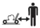
Keep persons and animals at a safe distance from the work area.

Look out for thrown objects and ricochets.
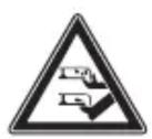
Warning: Keep hands and feet away from the rotating blade.

Warning: Keep hands and feet away from rotating parts.
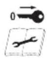
Remove the safety key before you do repair work or maintenance.
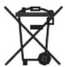
Environmental mark. The product or package of the product is not domestic waste. Recycle it at an approved
disposal location for electrical and electronic equipment.

The product agrees with applicable EC directives.

This product conforms to applicable UK regulations.

The product complies with applicable Eurasian Customs Union directives.

The product complies with applicable UkrSEPRO directives.

The product complies with applicable RCM directives. Applies to AU/NZ only.
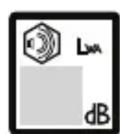
Noise emission to the environment label as per EU and UK directives and regulations, and New South Wales legislation "Protection of the Environment Operations (Noise Control) Regulation 2017". The guaranteed sound power level of the product is specified
in Technical data on page 29 and on the label.

Protected against splashing water.

Start procedure: push ON/OFF button, loosen start inhibitor, push motor brake handle down.

Release motor brake handle to stop.

Slow

Fast

Scannable code
Note: Other symbols/decals on the product refer to certification requirements for some markets.
Label on the product

DANGER – Keep hands and feet away.
Product liability
As referred to in the product liability laws, we are not liable for damages that our product causes if:
- the product is incorrectly repaired.
- the product is repaired with parts that are not from the manufacturer or not approved by the manufacturer.
- the product has an accessory that is not from the manufacturer or not approved by the manufacturer.
- the product is not repaired at an approved service center or by an approved authority.
Safety
Safety definitions
Warnings, cautions and notes are used to point out specially important parts of the manual.

WARNING: Used if there is a risk of injury or death for the operator or bystanders if the instructions in the manual are not obeyed.

CAUTION: Used if there is a risk of damage to the product, other materials or the adjacent area if the instructions in the manual are not obeyed.
Note: Used to give more information that is necessary in a given situation.
General safety instructions

WARNING: Read the warning instructions that follow before you use the product.
- This product is dangerous if used incorrectly or if you are not careful. Injury or death can
occur if you do not obey the safety instructions.
- This product produces an electromagnetic field during operation. This field may under some circumstances interfere with active or passive medical implants. To reduce the risk of serious or fatal injury we recommend persons with medical implants to consult their physician and the medical implant manufacturer before operating this product.
- Always be careful and use your common sense. If you are not sure how to operate the product in a special situation, stop and speak to your Husqvarna dealer before you continue.
- Keep in mind that the operator will be held responsible for accidents that involve other persons or their property.
- Keep the product clean. Make sure that you can clearly read signs and decals.
- Never allow children or people unfamiliar with these instructions to use the appliance. Local regulations may restrict the age of the operator.
- Always monitor a person, with decreased physical capacity or mental capacity, that uses the product. A responsible adult must be there at all times.
- Do not use the product if you are tired, ill, or under the influence of alcohol, drugs or medicine. This has a negative effect on your vision, alertness, coordination and judgment.
- Do not use the product if it is defective.
- Do not change this product or use it if it is possible that it has been changed by others.
Work area safety

WARNING: Read the warning instructions that follow before you use the product.
- Remove objects such as branches, twigs and stones from the work area before you use the product.
- Objects that hit against the cutting equipment can eject and cause damage to persons and objects. Keep bystanders and animals at a safe distance from the product.
- Never use the product in bad weather such as fog, rain,
Strong winds, intense cold, and risk of lightning. Using the product in bad weather or in moist or wet locations is tiring. Bad weather can cause dangerous conditions, such as slippery surfaces.
- Look out for persons, objects, and situations that can prevent safe operation of the product.
- Look out for obstacles, such as roots, stones, twigs, pits, and ditches. Long grass can hide obstacles.
- Cutting grass on slopes can be dangerous. Do not mow excessively steep slopes. Do not use the product on ground that slopes more than 15 degrees.
- Exercise extreme caution when changing direction on slopes. Operate the product across the face of slopes. Do not move up and down.
- Be careful when you go near hidden corners and objects that prevent a clear view.
Work safety

WARNING: Read the warning instructions that follow before you use the product.
- Use this product to cut grass lawns only. It is not permitted to use it for other tasks.
- Use personal protective equipment. Refer to Personal protective equipment on page 10.
- Make sure that you know how to stop the motor quickly in an emergency.
- Do not operate the product in rain or wet conditions. The risk of electrical shock increases if water enters the product.
- Do not operate the product unless the blade and all covers are attached correctly. An incorrectly attached blade can come loose and cause personal injury.
- Make sure that the blade does not hit objects such as stones and roots. This can do damage to the blade and bend the motor shaft. A bent axle causes heavy vibration and a very high risk that the blade becomes loose.
- If the blade hits an object or if vibrations occur, stop the product immediately. Stop the motor, pull up the safety key, and remove the battery. Examine the product for damages. Repair damages or
let an authorised service agent do the repair.
- Never attach the motor brake handle permanently to the handle when the motor is started.
- Put the product on a stable, flat surface and start it. Make sure that the blade does not hit the ground or other objects. Always stay behind the product when you operate it.
- Let all the wheels stay on the ground and keep 2 hands on the handle when you operate the product. Keep your hands and feet away from the rotating blades.
- Do not tilt the product when the motor is started.
- Be careful when you pull the product rearward.
- Never lift up the product when the motor is started. If you must lift the product, first stop the motor, pull up the safety key and remove the battery.
- Do not walk rearward when you operate the product.
- Stop the motor when you move across areas without grass, for example paths made of gravel, stone and asphalt.
- Do not run with the product when the motor is started.
Always walk when you operate the product.
- Stop the motor before you change the cutting height. Never make adjustments with the motor started.
- Never let the product stay out of view with the motor started. Stop the motor and make sure that the cutting equipment does not rotate.
Safety instructions for operation
Personal protective equipment

WARNING: Read the warning instructions that follow before you use the product.
- Personal protective equipment cannot fully prevent injury but it decreases the degree of injury if an accident does occur. Let your dealer help you select the right equipment.
- Use heavy-duty slip-resistant boots or shoes. Do not use open shoes or go with bare feet.
- Use heavy, long pants.
- Use protective gloves when necessary, for example when you attach, examine or clean the cutting equipment.
Safety devices on the product

WARNING: Read the warning instructions that follow before you use the product.
- Do not use a product with defective safety devices.
- Do not remove or do modifications to safety devices.
- Do a check of the safety devices regularly. If the safety devices are defective, speak to your Husqvarna service agent.
To do a check of the cutting cover
The cutting cover decreases vibrations in the product and decreases the risk of injury from the blade.
- Examine the cutting cover to make sure that there are no damages such as cracks.
Safety key
The safety key is below the battery lid. The safety key connects the battery that supplies the motor with power.
To do a check of the safety key
The safety key connects the battery that supplies the motor with power.
- Start and stop the motor. If the safety key operates correctly, the motor can only start when the key is in the safety lock.
Motor brake handle
The motor brake handle stops the motor. When the motor brake handle is released, the motor stops.
To do a check of the motor brake, start the motor and then release the motor brake handle. If the motor does not stop in 3 seconds, let an approved Husqvarna service agent adjust the motor brake.
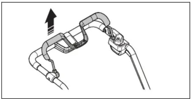
To examine the start inhibitor
Do a check of the start inhibitor to make sure that it prevents operation of the motor.
- Push the motor brake handle in the direction of the handlebar. The start inhibitor stops the movement.
- Push the start inhibitor out.
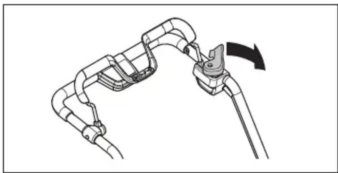
- Release the start inhibitor and make sure that it goes back to its initial position.
Battery safety

WARNING: Read the warning instructions that follow before you use the product.
- Use Husqvarna rechargeable batteries as a power supply for related Husqvarna products only. To prevent injury, do not use the battery as a power supply for other devices.
- Do not use non-rechargeable batteries.
- Risk of electrical shock. Do not connect the battery terminals to keys, coins, screws or other metal. This can cause a short circuit of the battery.
- Do not put objects into the air slots of the battery.
- Keep the battery away from sunlight, heat or open flame. The battery can explode and cause burns and/or chemical burns.
- Keep the battery away from rain and wet conditions.
- Keep the battery away from microwaves and high pressure.
- Do not try to disassemble or break the battery.
- If the battery leaks, do not let the liquid touch your body or eyes. If you have touched the liquid, clean the area with a large quantity of water and get medical aid.
- Use the battery in temperatures between -10°C and 40°C.
- Do not clean the battery or the battery charger with water. See To clean the battery and the battery charger on page 27.
- Do not use a defective or damaged battery.
- Keep batteries in storage away from metal objects such as nails, coins, jewellery.
Battery charger safety

WARNING: Read the warning instructions that follow before you use the product.
- Use the QC battery chargers to charge Husqvarna replacement batteries only.
- Risk of electrical shock or short circuit. Do not put objects into the air slots of the charger. Do not try to disassemble the battery charger. Do not connect the charger terminals to metal objects. Use an approved mains socket.
- This product produces an electromagnetic field during operation. This field may under some circumstances interfere with active or passive medical implants. To reduce the risk of serious or fatal injury, we recommend persons with medical implants to consult their physician and the medical implant manufacturer before operating this product.
- Regularly make sure that the power cord of the battery charger is not damaged and that there are no cracks in it.
- Do not lift the battery charger by the power cord. To disconnect the battery charger from a mains socket, pull out the plug. Do not pull the power cord.
- Keep the power cord and extension cables away from water, oil and sharp edges. Make sure that the cable is not pinched in doors, fences or equivalent. It can cause the charger to become energized.
- Do not clean the battery charger with water.
- The battery charger can be used by children aged from 8 years and above and persons with reduced physical, sensory, or mental capabilities or lack of experience and knowledge if they have been given supervision or instruction concerning use of the battery charger in a safe way and understand the hazards involved. Children shall not play with the battery charger. Cleaning and user maintenance shall not be made by children without supervision.
- Do not charge non-rechargeable batteries in the battery charger.
- Do not use the battery charger near flammable materials or materials that can cause corrosion. Do not cover the battery charger. Pull out the plug to the battery charger if there is smoke or fire.
- Do not use a defective or damaged battery charger.
- Only charge the battery indoors in a room with good airflow and away from sunlight. Do not charge the battery in wet conditions.
Safety instructions for maintenance

WARNING: Read the warning instructions that follow before you use the product.
- Remove the safety key before you do maintenance on the product.
- Do the maintenance work correctly to increase the lifetime of the product and decrease the risk of accidents. Let an approved service agent do the professional repairs. Speak to your nearest service agent for more information.
- Only do the maintenance work written in this operator's manual.
- Put on heavy duty gloves when you use the cutting equipment. The blade is very sharp and cuts can easily occur.
- Keep the cutting edges sharp and clean for the best and safest performance.
- Let your service agent regularly examine the product and make necessary adjustments and repairs.
- Replace damaged, worn or broken parts.
- Obey the instructions for how to change accessories. Only use accessories from the manufacturer.
- When not in operation, keep the product, battery and battery charger apart in a dry, indoor and locked area. Make sure that children and persons that are not approved cannot get access to the product, battery or battery charger.
Assembly
Introduction

WARNING: Read and understand the safety chapter before you assemble the product.
To install and remove the multi battery (accessory)
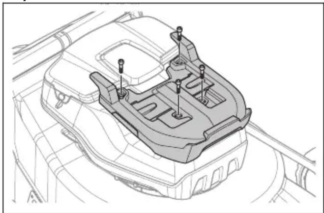
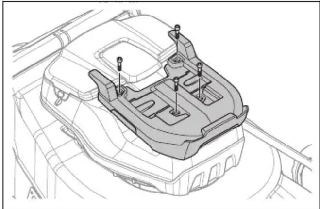
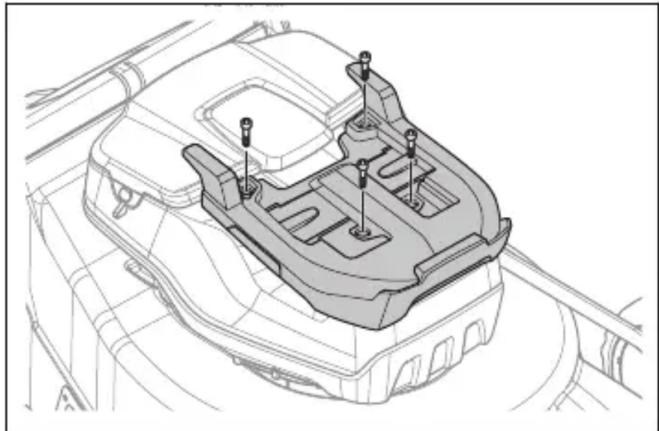
- Remove the 4 rubber covers and the 4 screws from the motor cover.

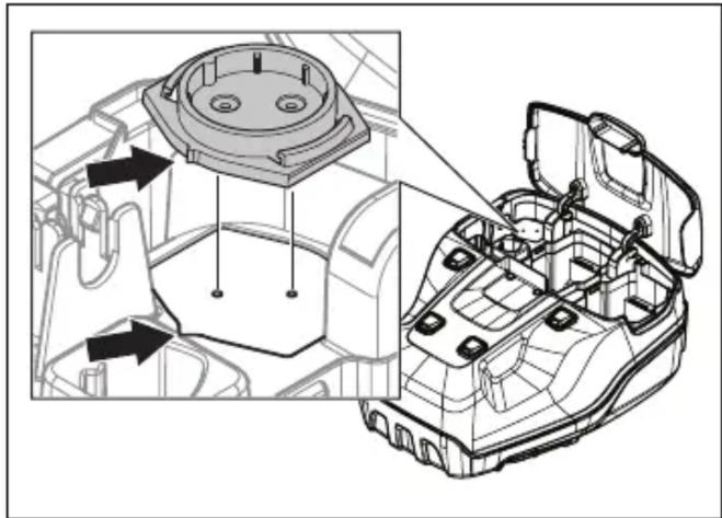
- Put the adapter plate onto the motor cover.
- Attach the adapter plate with the 4 supplied screws to a torque of 5-6 Nm.
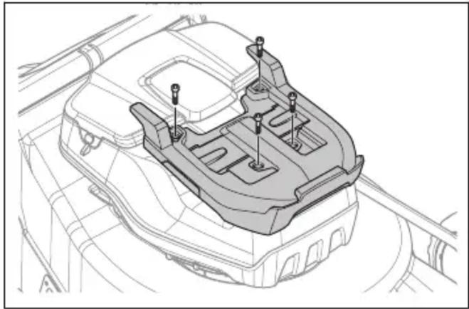
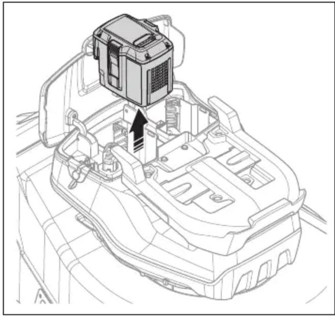
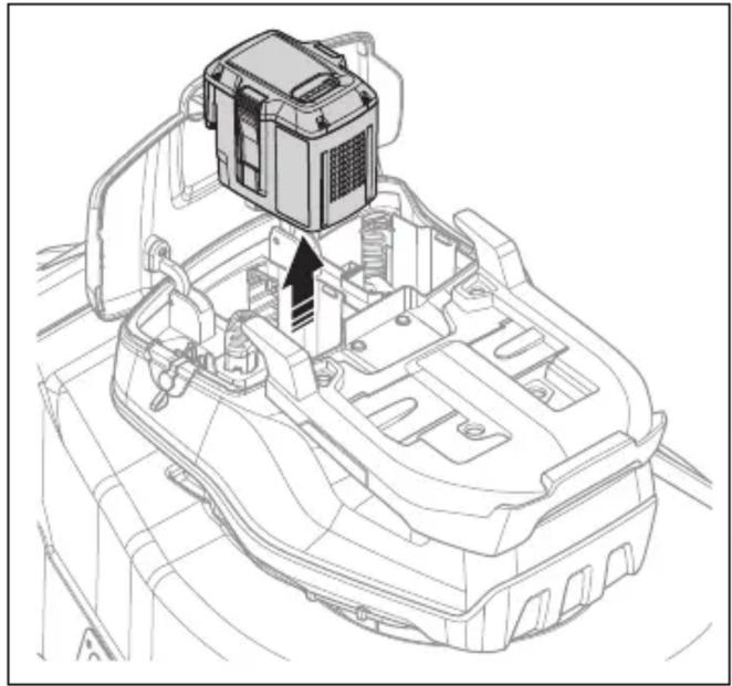
- Open the battery hatch.
- Remove the battery in slot 1.
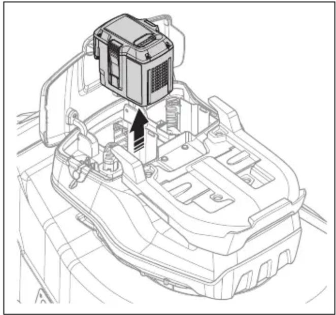
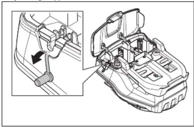
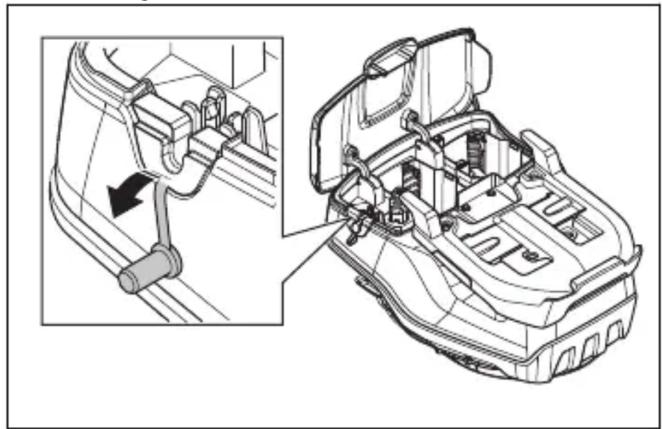
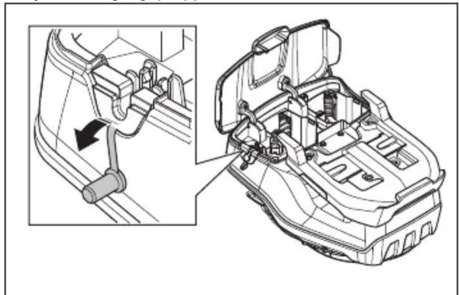
- Remove the seal stop.
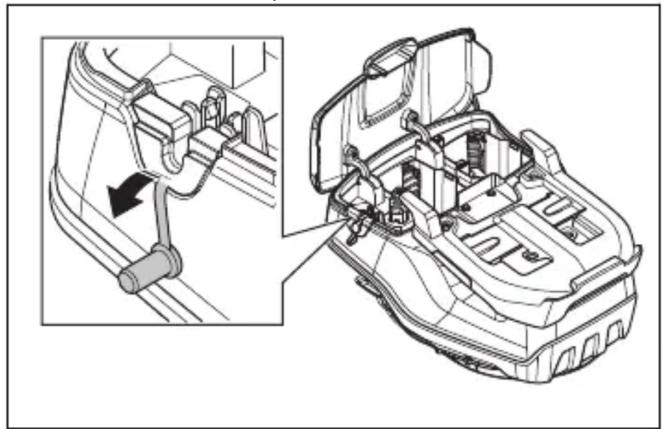
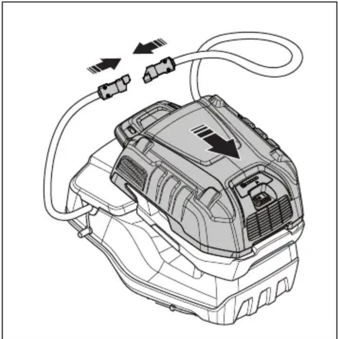
- Push the battery adapter into the battery compartment until you hear a click.
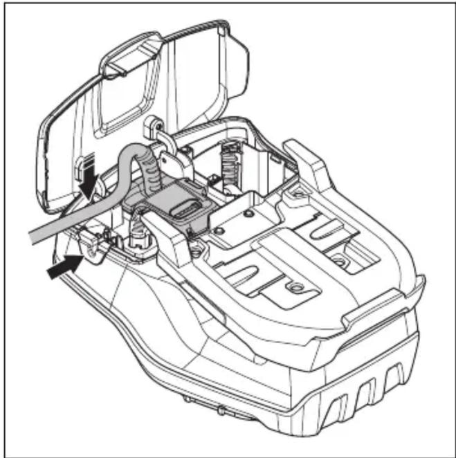
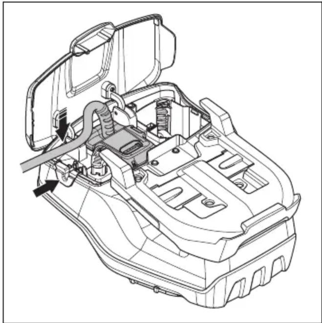
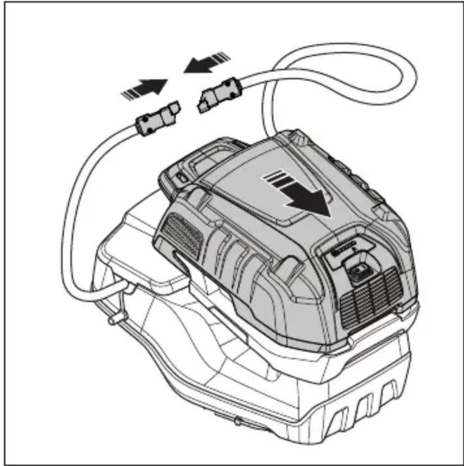
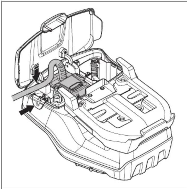
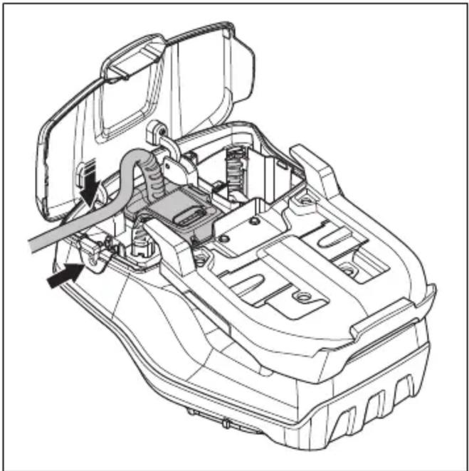
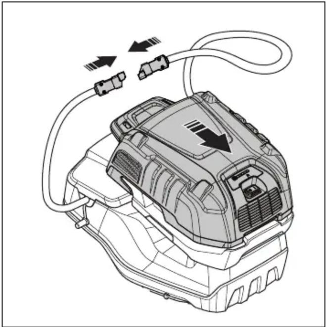
- Put the cord of the battery adapter through the seal stop hole. Attach the cord with the clip.
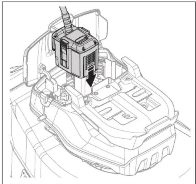
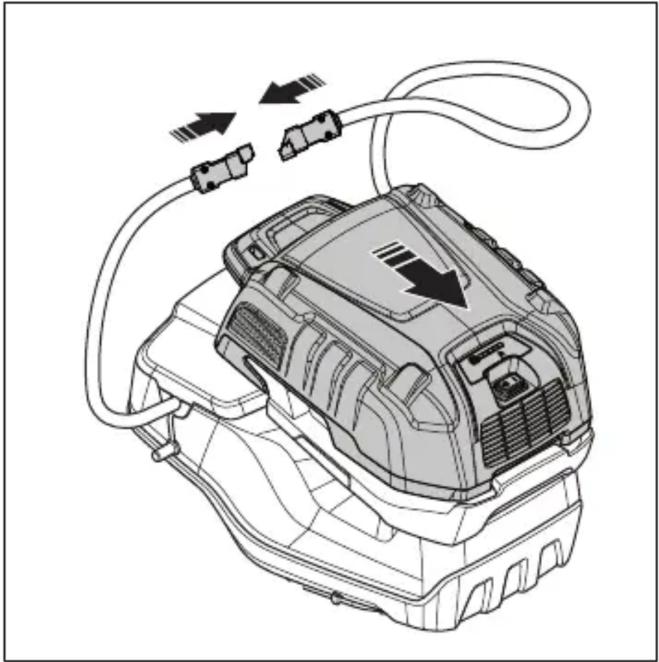
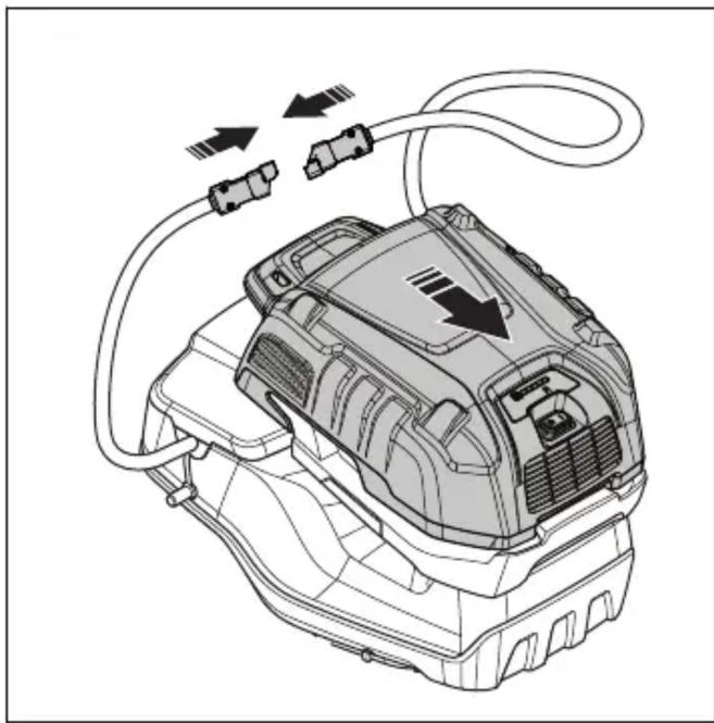
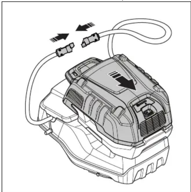
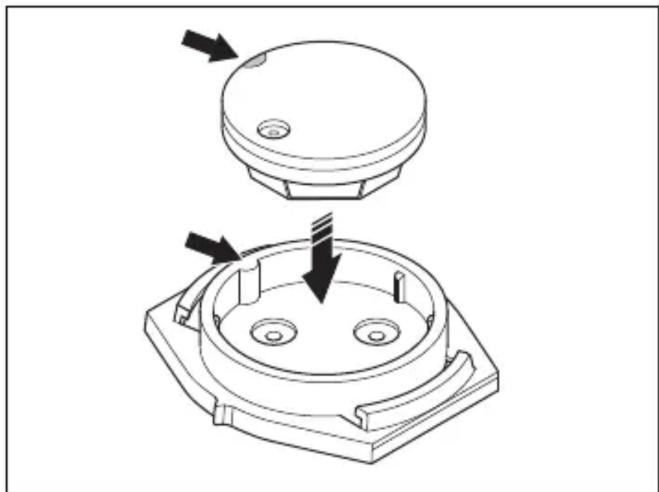
- Install the multi battery onto the battery adapter.
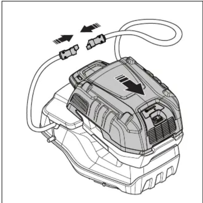
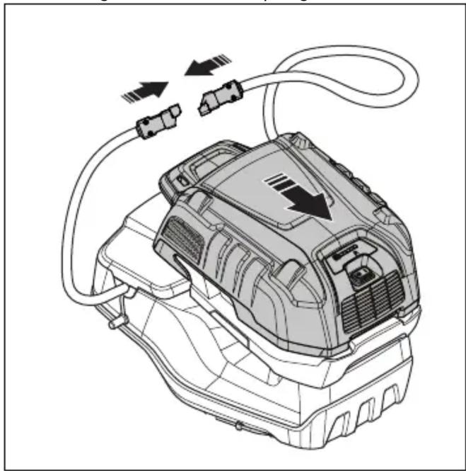
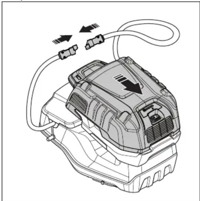
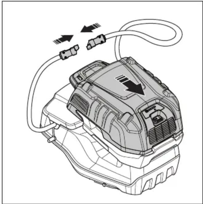
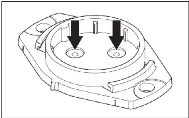
- Connect the multi battery to the battery adapter.
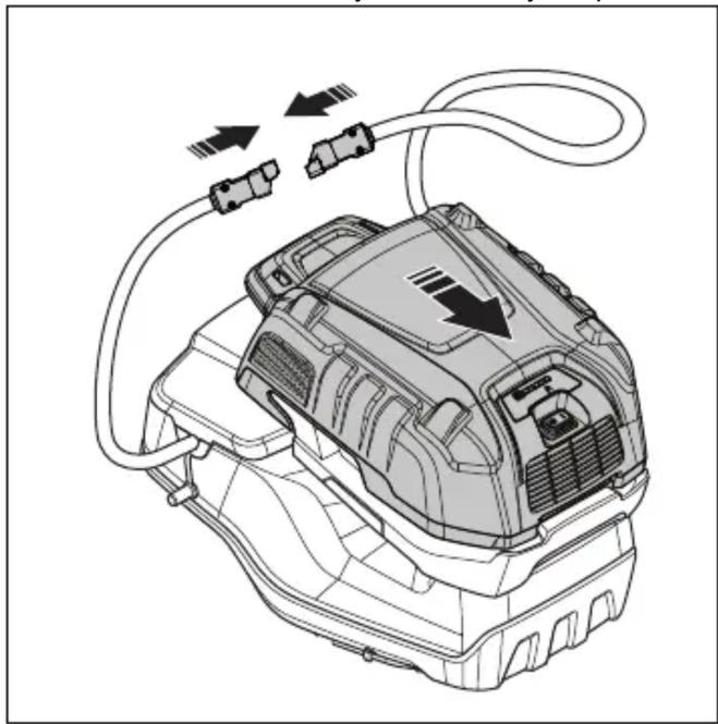
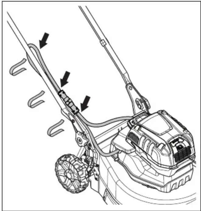
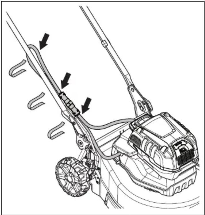
- Attach battery adapter cord to the handle with the 3 fabric straps.
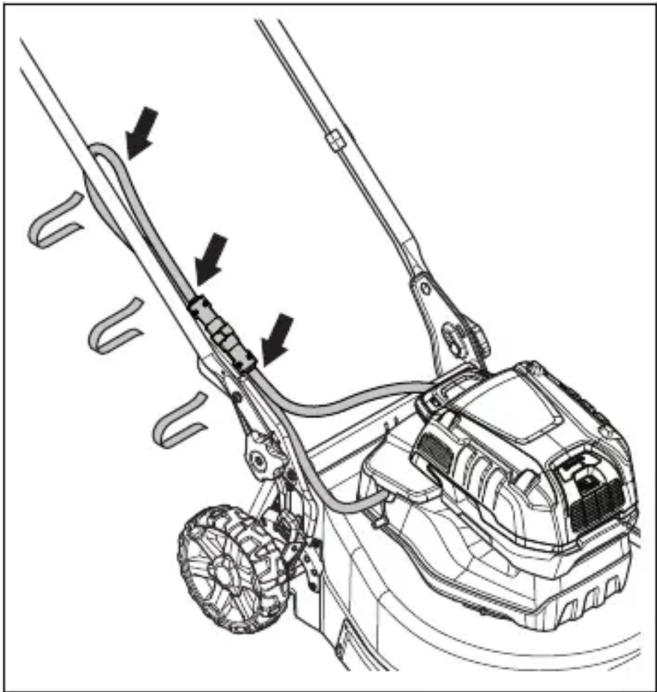
- Remove the multi battery in the opposite sequence.

WARNING: Do not attach the cord too loosely to the handle. The cord can come off the handle and cause injury.
To adjust the handle (LC 551iV)
- Loosen the lower knobs.
- Move the knobs to the lower end of the grooves on the left and the right side of the product.
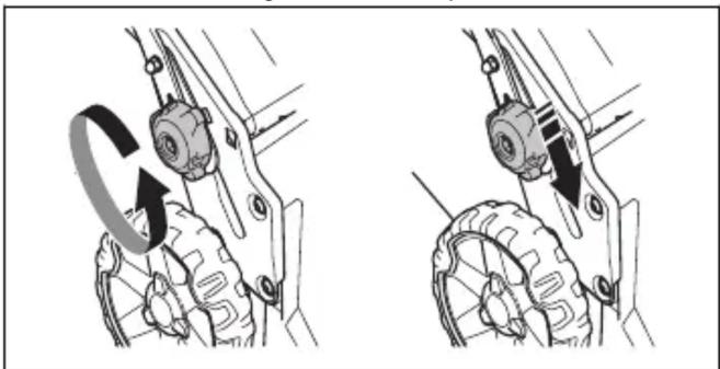
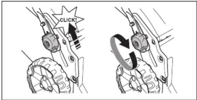
- Set the handle height in one of the 2 available positions.
- Move the knobs up in the direction of the handle until they stop and you hear a click.
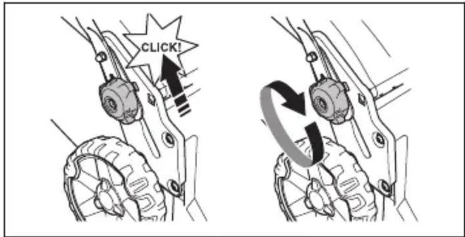
- Tighten the knobs fully.
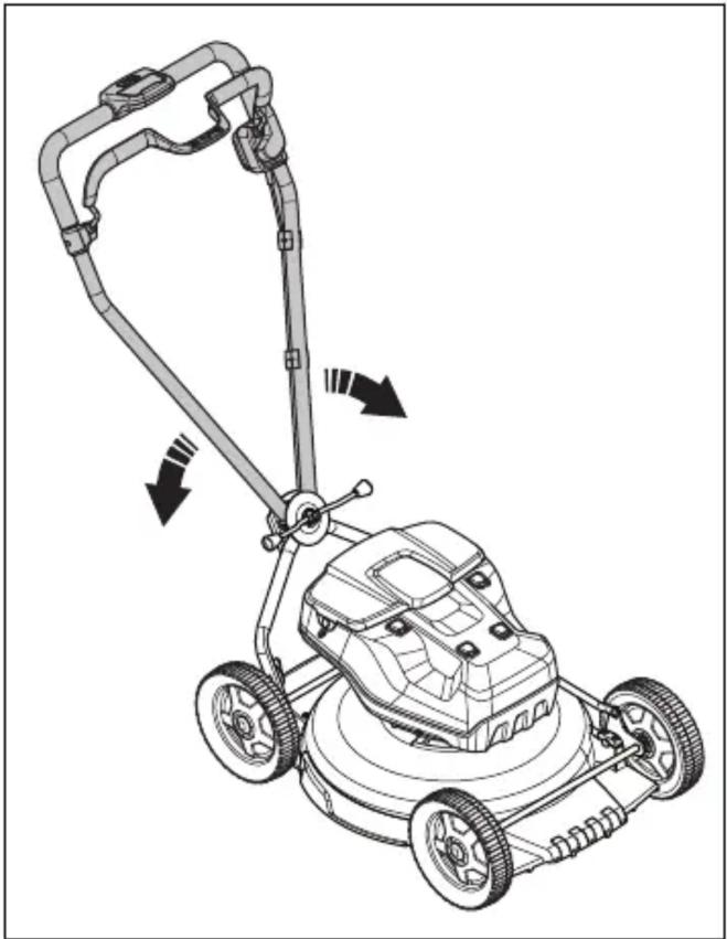
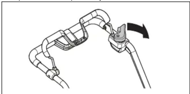
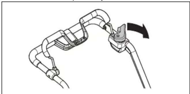
To assemble the handle (LB 548i, LB 553iV)
- Remove the handle nut and the washer from the plate on the upper handle.
- Put the upper handle in position on top of the lower handle.

CAUTION: Make sure that the wires are not caught or become damaged.
- Attach the washer and the handle adjustment lever.
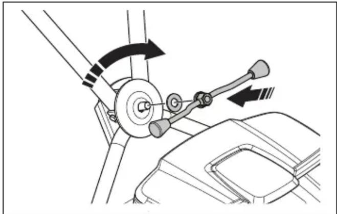
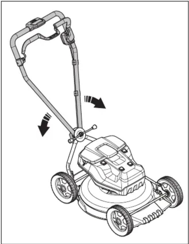
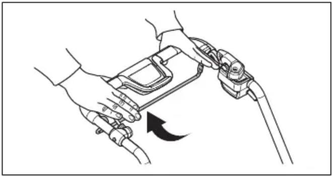
- Turn the handle to the side for a good operation position when you operate the product near a wall.
To assemble the grass catcher (LC 551iV)
- Attach the grass catcher frame to the grass bag with the rigid part of the bag on the bottom. Keep the handle of the frame on top of the grass bag.
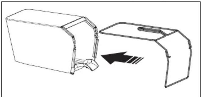
- Attach the bottom section of the grass catcher frame in the groove on the bottom of the grass catcher.
- Attach the grass bag to the grass catcher frame with the clips.
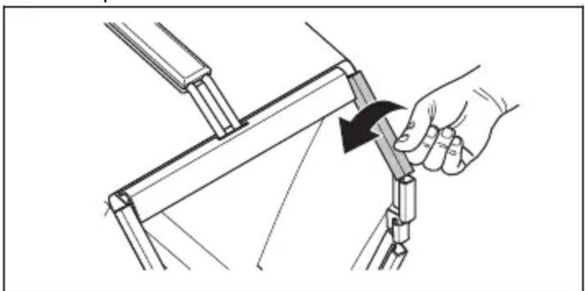
- Lift the rear cover.
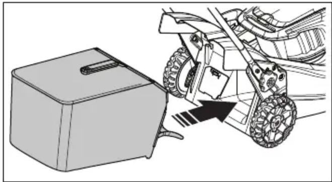
- Attach the grass catcher to the top edge of the chassis.
- Put the lower part of the grass catcher into the grass discharge channel.
To assemble the mulch plug (LC 551iV accessory)
- Lift up the rear cover and remove the grass catcher.
- Put the mulch plug into the discharge channel.
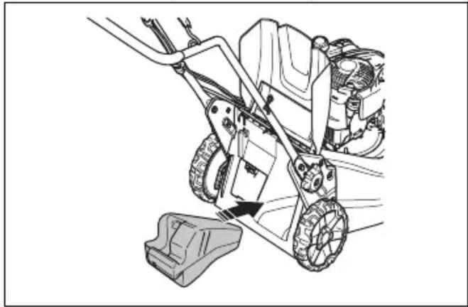
- Replace the blade with the mulch blade that is supplied with the mulch kit. Refer to To replace the blade on page 26.
Operation
Introduction

WARNING: Before you operate the product, you must read and understand the safety chapter.
Husqvarna Connect
Husqvarna Connect is a free app for your mobile device. The Husqvarna Connect app gives extended functions for your Husqvarna product:
- Extended product information. • Information about, and help with, product parts and servicing.
To start to use Husqvarna Connect
- Download the Husqvarna Connect app on your mobile device.
- Register in the Husqvarna Connect app.
- Do the instruction steps in the Husqvarna Connect app to connect and register the product.
Husqvarna Fleet Services™
Husqvarna Fleet Services™ is a cloud solution that gives the commercial fleet manager an overview of all products. It is a requirement to have the Husqvarna Fleet Services™ sensor installed on the product. The product is prepared for installation of a Husqvarna Fleet Services™ sensor. For more information about Husqvarna Fleet Services™, refer to www.husqvarna.com.
To prepare the sensor (accessory)
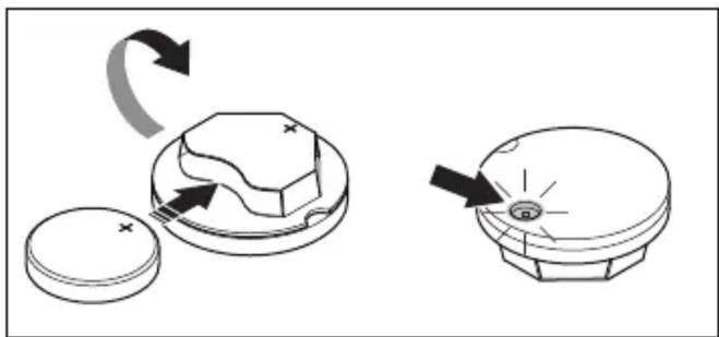
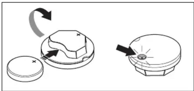
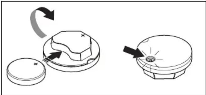
- Use the sensor key to open the lid of the sensor.
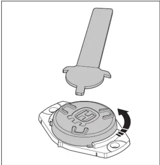
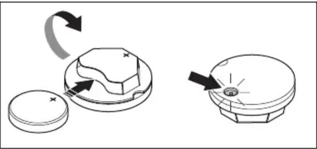
- Remove the sensor.
- Connect the battery to the sensor. The LED light of the sensor comes on.

- Download the Husqvarna Fleet Services™ app.
- Log on to the Husqvarna Fleet Services™ app.
- Do a pairing operation. Refer to "To do a pairing operation between the app and the product" on page 18.
To do a pairing operation between the app and the product
- Log on to the Husqvarna Fleet Services™ app.
- Select your product in the app.
- Scan the code behind the sensor with your mobile device to install the sensor in the app.
Note: It is only necessary to do a pairing operation between the app and the product one time.
To install the sensor
- Make sure that the sensor is connected to the Husqvarna Fleet Services™ app. Refer to "To do a pairing operation between the app and the product" on page 18.
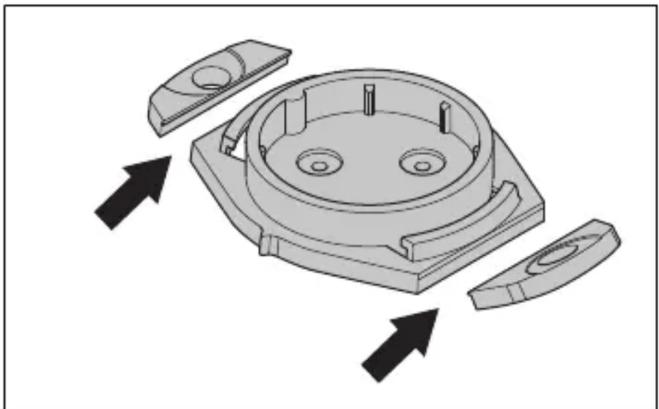
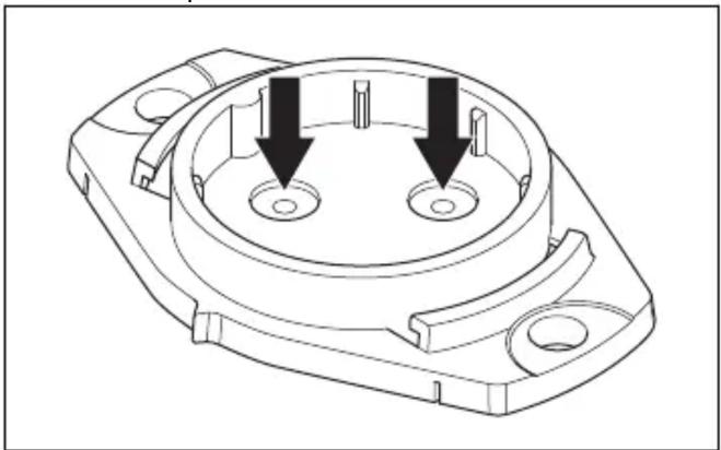
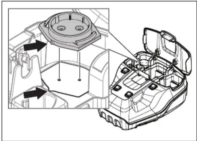
- Drill 2 holes by the marks in the enclosure slot.
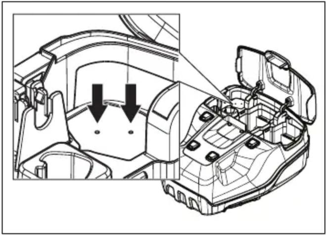
Note: Make sure that the holes are the same dimension as the rivets supplied with the sensor.
- Use a pair of pliers to remove the outer holes on the sensor slot.
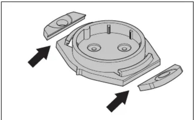
- Drill 2 holes by the marks in the sensor slot.
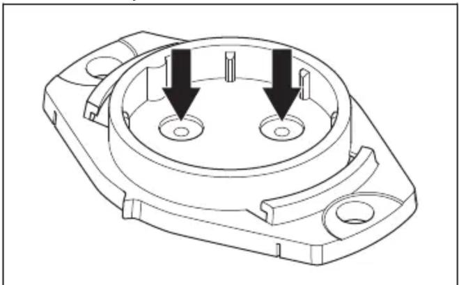
- Align the sensor slot with the enclosure slot.
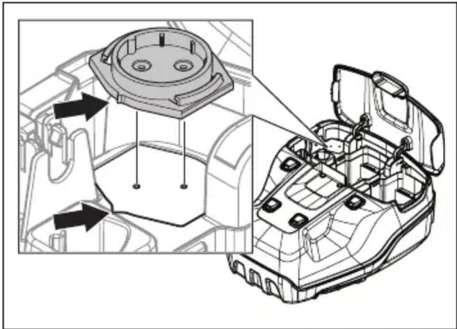
- Attach the sensor slot with the rivets.
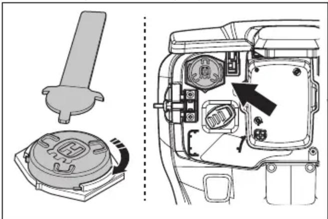
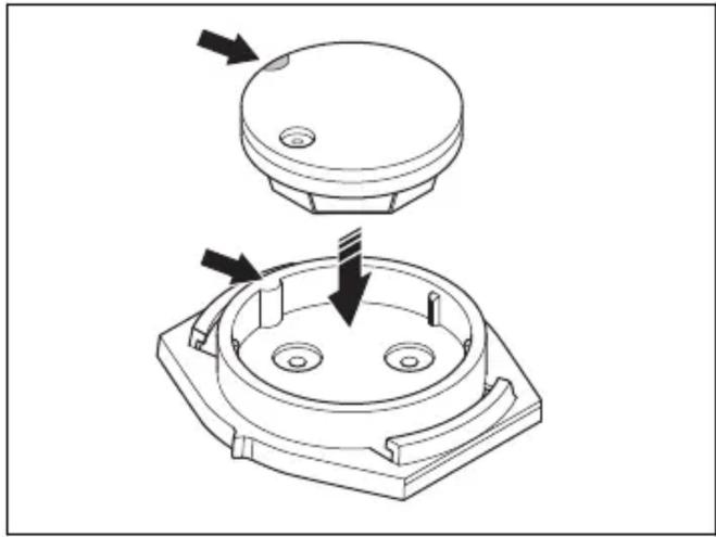
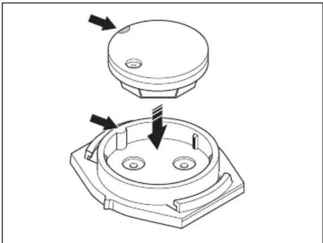
- Install the sensor in the sensor slot. Align the white mark on the sensor with the mark on the sensor slot.

- Close the lid to the sensor and lock it with the sensor key. Make sure that the top of the Husqvarna "H" points away from the safety key.
To set the product in operation position (LC 551iV)
- Lift the handle to upright position.
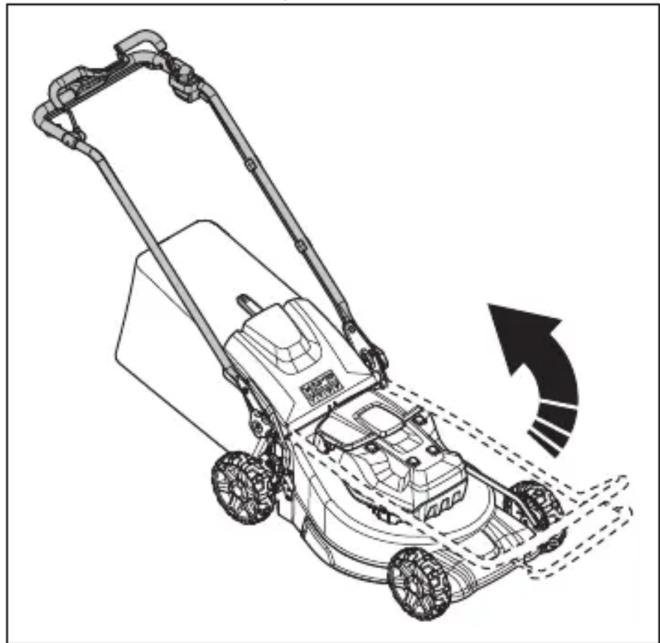
- Move the knobs up in the direction of the handle until they stop and you hear a click.
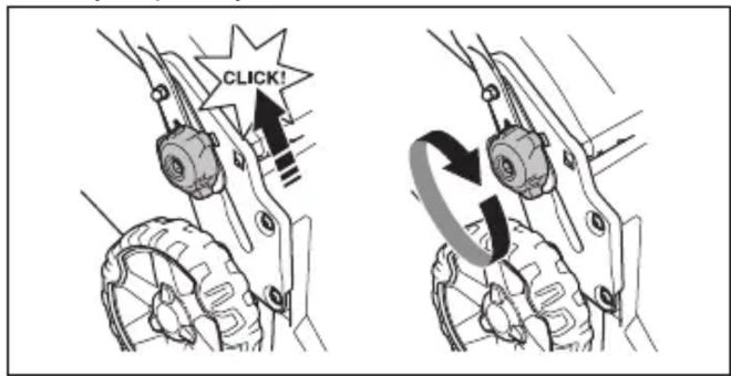
- Tighten the knobs fully.
To set the cutting height (LB 548i, LC 551iV)
The cutting height can be adjusted in 6 levels.
- Push the cutting height control in the direction of the wheel and then rearward to increase the cutting height.
- Push the cutting height control in the direction of the wheel and then forward to decrease the cutting height.


CAUTION: Do not set the cutting height too low. The blades can hit the ground if the surface of the lawn is not level.
To set the cutting height (LB 553iV)
The cutting height can be adjusted in 5 levels.
- Move the cutting height lever rearward to increase the cutting height.
- Move the cutting height lever forward to decrease the cutting height.
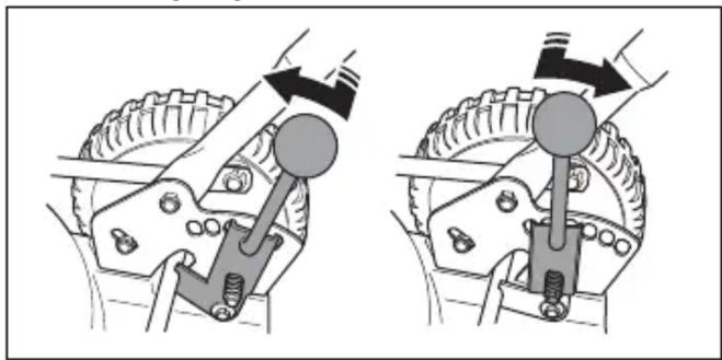

CAUTION: Do not set the cutting height too low. The blades can hit the ground if the surface of the lawn is not level.
Battery

WARNING: Before you use the battery, you must read and understand the safety chapter. You must also read and understand the operator's manual for the battery and the battery charger.
Battery status
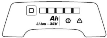
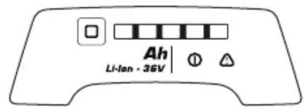
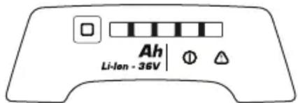
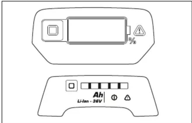
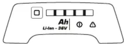
The display shows the remaining battery capacity and if there are problems with the battery. The battery capacity is shown for 5 seconds after the product is switched off or the battery indicator button is pressed. The warning
symbol on the battery is on when an error has occurred. See Battery on page 27.
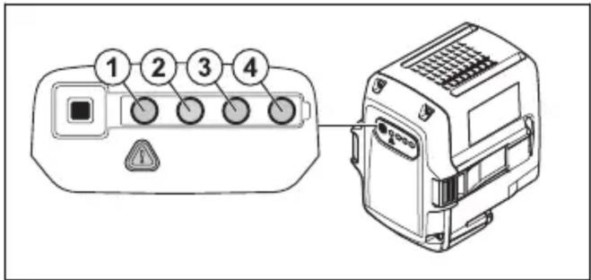
| LED lights Battery status | |
| All LEDs are lit Fully charged | (75-100%) |
| LED 1, LED 2, LED 3 are lit | The battery is 50%-75% charged |
| LED 1, LED 2 are lit The battery is 25%-50% charged | |
| LED 1 is lit The battery is 0%-25% charged. | |
| LED 1 flashes The battery is empty.Charge the battery. | |
To charge the battery
Charge the battery before the first use. The battery is only 30% charged when supplied to the customer.
Note: The battery charger must be connected to the voltage and frequency specified on the rating plate.
The battery does not charge if the battery temperature is above 50°C. The battery charger decreases the temperature of the battery before it starts to charge.
- Connect one end of the power cord for the battery charger into the socket of the battery charger.
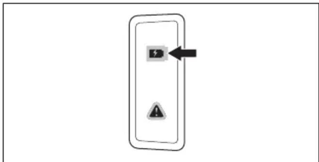
- Connect the other end of the power cord for the battery charger in a grounded mains socket. The LED on the battery charger flashes green one time.
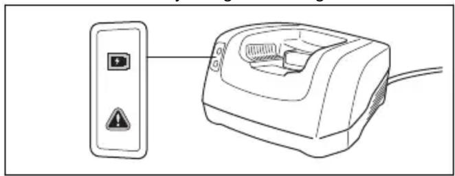
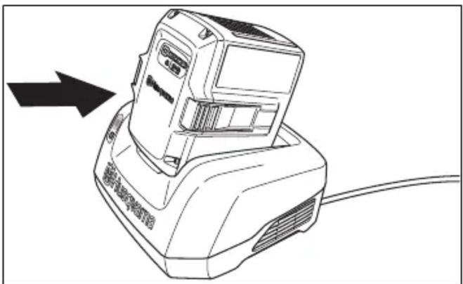
- Put the battery in the battery charger. The green light on the charger comes on when the battery is correctly connected to the battery charger.
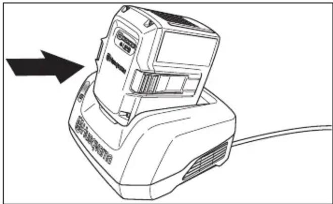
- When all LEDs on the battery have come on the battery is fully charged. Charge the battery for maximum 24 hours.
- To disconnect the battery charger from the mains socket, pull the plug, not the power cord.
- Remove the battery from the battery charger.
Battery charging status
A Husqvarna Li-ion battery can be charged or used at all charging levels. The battery is not damaged. A fully charged battery will not decrease its charge when the battery is left in the charger.
| LED display | Charging status |
| LED 1 flashes 0%-25% | |
| LED 1 is lit, LED 2 flashes | 25%-50% |
| LED 1, LED 2 are lit, LED 3 flashes | 50%-75% |
| LED 1, LED 2, LED 3 are lit, LED 4 flashes | 75%-100% |
| LED 1, LED 2, LED 3, LED 4 are lit | Fully charged |
To charge the multi battery
Note: Charge the battery if it is the first time that you use it. A new battery is only 30% charged.
- Make sure that the battery is dry.
- Connect the multi battery to the adapter.
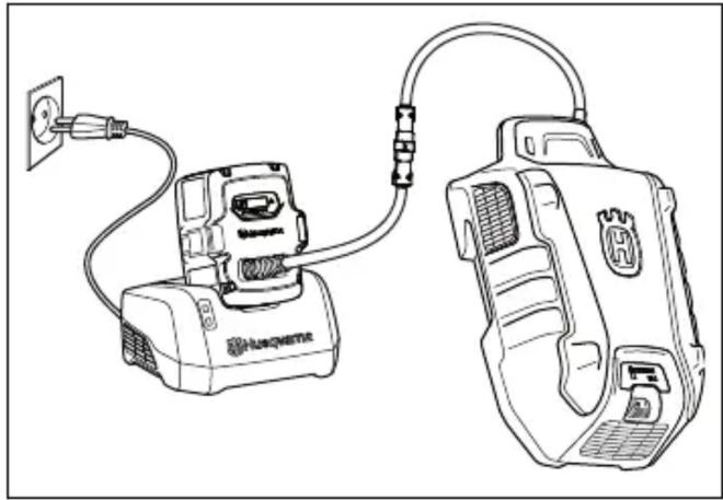
- Put the adapter in the battery charger.
- Make sure that the green charging LED on the battery charger comes on. That means that the adapter and multi battery are connected correctly.
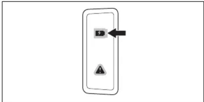
- When all LEDs on the battery come on and the adapter shows 100%, the battery is fully charged.
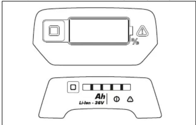
The adapter shows the state of charge in steps of 1%. Small deviations are possible at the start of the charge.
- To disconnect the battery charger from the mains socket, pull the plug. Do not pull the cable.
- Remove the adapter from the battery charger.
- Remove the multi battery from the adapter.
Note: Refer to the multi battery and battery charger manuals for more information.
To start the product
- Lift the battery lid.
- Put a charged battery in battery slot number 1 below the battery lid. For longer operation time, put a second charged battery in battery slot number 2.
- Disconnect the safety key from the safety key holder.
- Push the safety key into the safety lock.
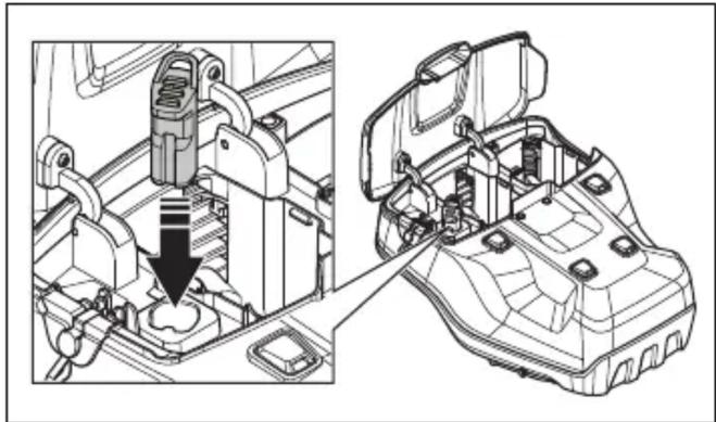
- Stay behind the product.
- Press the ON/OFF button on the control panel. The display turns on.
- Release the start inhibitor.
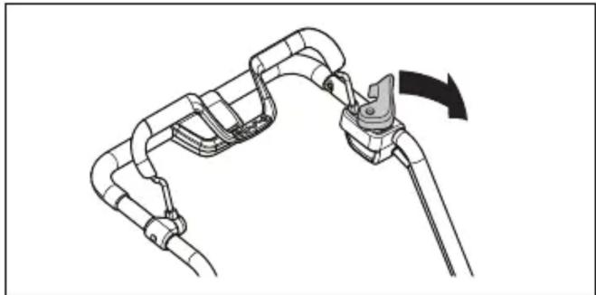
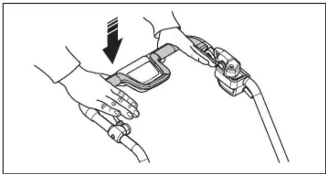
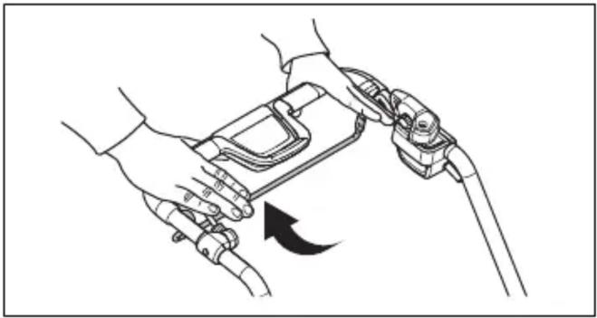
- Push the motor brake handle toward the handlebar.
To use the wheel drive (LC 551iV)
- Pull the drive bail toward the handlebar to engage the drive.
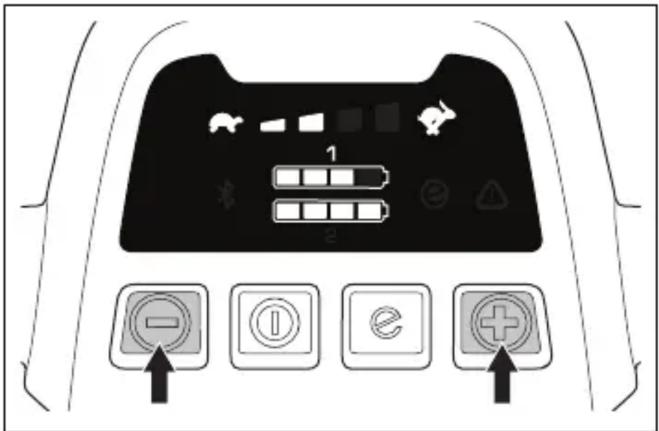
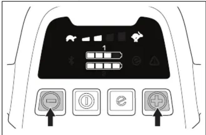
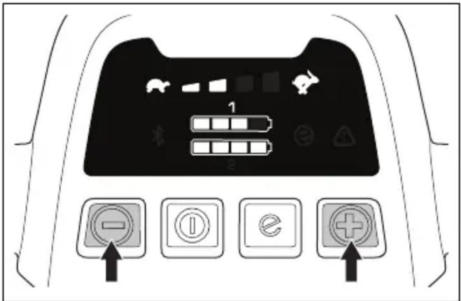
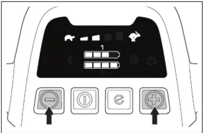
- Press + and - on the control panel to set the drive speed in 4 steps.
- Release the drive bail to disengage the drive, for example when approaching an obstacle.
To use the wheel drive (LB 553iV)
- Start the product, see "To start the product" on page 22.
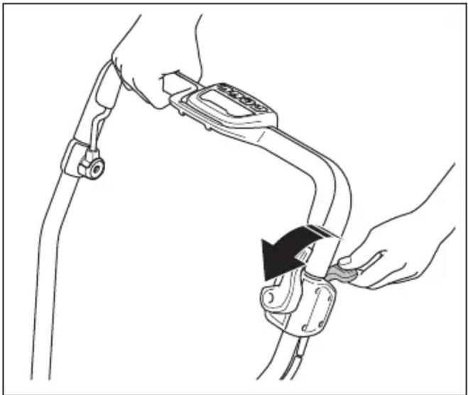
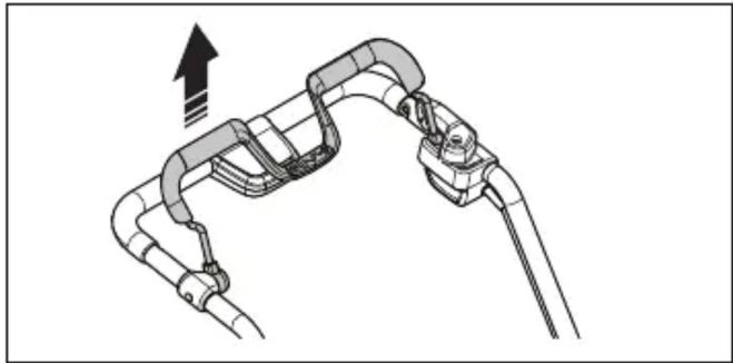
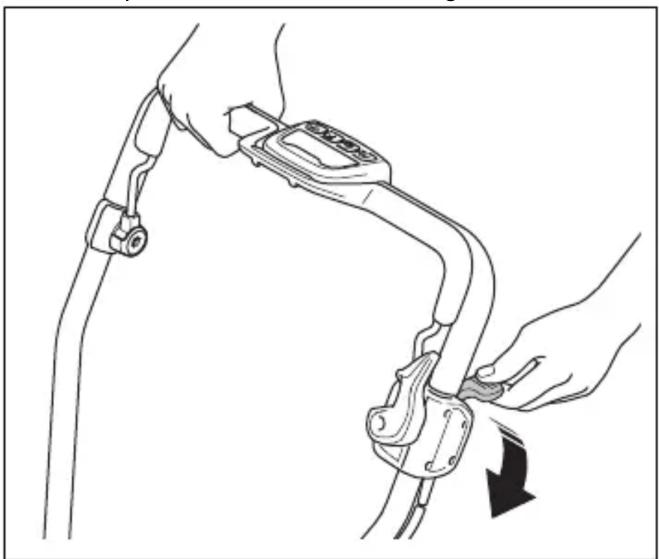
- Pull the drive control lever up to engage the drive.
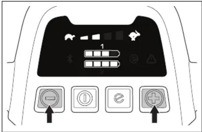
- Press the + and - buttons on the control panel to set the drive speed.
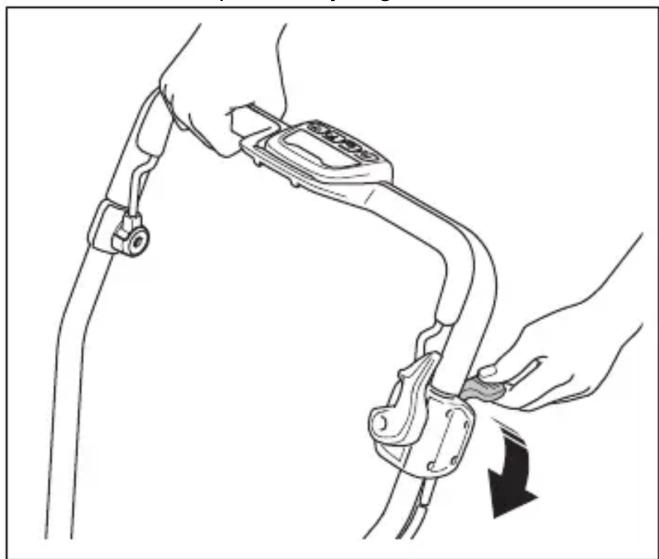
- Push the drive control lever down to disengage the drive, for example when approaching an obstacle.
To move the product with the cutting equipment disengaged (LB 553iV)
- Engage the start inhibitor.
- Pull up the drive control lever.
- Hold the drive control lever and move the product.
- Release the drive control lever and disengage the start inhibitor to continue operation.
To use the SavE function
The product has a battery saving function (SavE) that provides longer operation time.
- Press the SavE button (A) to activate the function. The SavE symbol (B) appears on the display.
- Press the SavE button again to deactivate the function. The SavE symbol (B) disappears from the display.
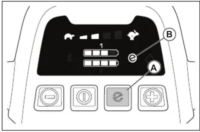
Note: The SavE function automatically stops if ground conditions require higher output. The SavE function automatically resumes when ground conditions allow.
PowerBoost function
When the product cuts long or wet grass, the motor automatically increases RPM. To save battery power, the motor automatically returns to standard mode when the PowerBoost function is not needed.
Motor stalling
During operation, the blade and motor may temporarily stop due to obstacles such as grass blockage under the cutting cover. If this occurs and you keep the motor brake handle pressed down, the product restarts automatically. If the product does not restart within 5-10 seconds, it may be necessary to clean under the cutting cover. Refer to "To clean the product" on page 27.

WARNING: If the motor stops, the product attempts to restart automatically for 5-10 seconds. Wait at least 15 seconds before inspecting the cutting cover.

WARNING: Before checking the cutting cover, release the motor brake handle, turn the safety key to 0, remove the battery, and wait for a minimum of 5 seconds. There is a risk of injury if the obstacle is removed and the product accidentally starts.
To stop the product
The product stops automatically if you do not operate it for 3 minutes.
- Release the motor brake handle to stop the motor.
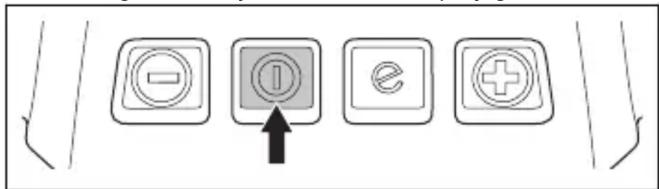
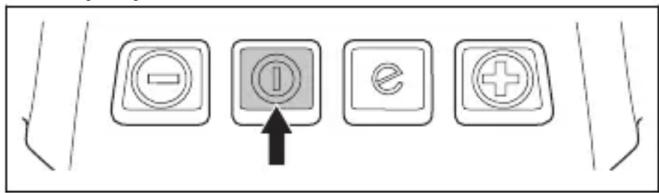
- Push the ON/OFF button on the control panel. All LED lights and symbols on the display go out.
- Remove the safety key from the safety lock and put it in the safety key holder.
To get a good result
• Always use a sharp blade. A blunt blade gives an irregular result and the cut surface of the grass becomes yellow. A sharp blade also uses less energy than a blunt blade. - Do not cut more than 1/3 of the length of the grass. Cut first with the cutting height set high. Examine the result and lower the cutting height to an applicable level. If the grass is very long, drive slowly and cut 2 times if necessary. - Cut in different directions each time to prevent stripes in the lawn. - Keep the cutting cover clean. Buildup from grass and dirt on the inner side of the cutting cover can decrease the cutting result. Refer to To clean the product on page 27.
To cut grass without a grass catcher or mulch plug attached (LC 551iV)
- Lift up the rear cover and remove the grass catcher.
- If a mulch plug and a mulch blade are attached, remove them.
- Close the rear cover before you operate the product.
When you operate the product, the cut grass discharges below the rear cover.
Maintenance
Introduction

WARNING: Before you do maintenance, you must read and understand the safety chapter.
For all servicing and repair work on the product, special training is necessary. We guarantee the availability of professional repairs and servicing. If your dealer is not a service agent, speak to them for information about the nearest service agent.
For more detailed information, refer to www.husqvarna.com.
Maintenance schedule
The maintenance intervals are calculated from daily use of the product. The intervals change if the product is not used daily.
For maintenance identified with *, refer to Safety instructions for operation on page 10.
| Each use | Monthly | Each season | |
| Do a general inspection. X | |||
| Clean the transmission covers. Make sure that the motor does not have grass on it. | X | ||
| Do a check of the start inhibitor. * X | |||
| Make sure that the safety devices on the product are not defective. * X | |||
| Examine the grass catcher for wear or deterioration. X | |||
| Examine the cutting equipment. X | |||
| Examine the cutting cover. * X | |||
| Do a check of the motor brake handle. * X | |||
| Make sure that the ON/OFF button operates correctly and is not defective. X | |||
| Examine the battery for damage. X | |||
| Do a check of the battery charge X | |||
| Make sure that the release buttons on the battery operates correctly and that the battery locks into the product. | X | ||
| Clean the air intakes. Make sure that the air intakes do not have grass or dirt on them. | X | ||
| Examine the battery charger for damage and make sure that it operates correctly. | X | ||
| Clean below the protection cover (LC 551iV, LB 553iV). X | |||
| Examine the connections between the battery and the product. Also examine the connection between the battery and the battery charger. | X |
To do a general inspection
- Make sure that the nuts and screws on the product are tightened.
- Make sure that the cables on the product are not in a position where they can get damaged.
To replace the blade
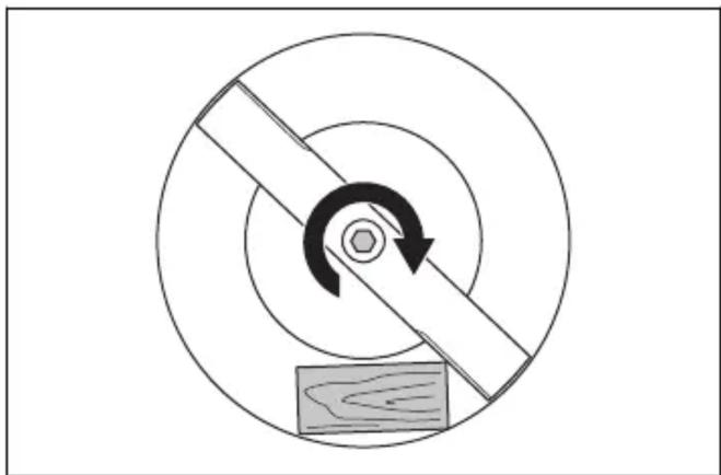
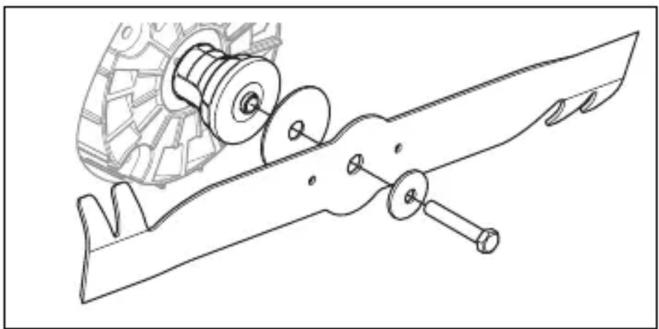
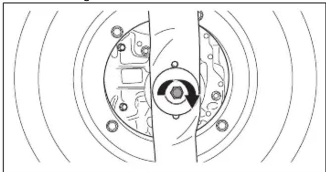
- Lock the blade with a block of wood.
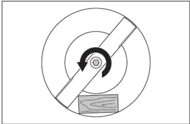
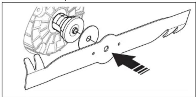
- Remove the blade bolt, the spring washer and the blade.
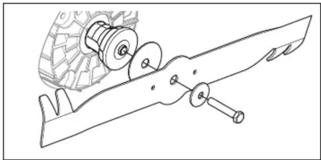
- Examine the blade support and blade bolt for damages.
a) If you replace the blade or the blade support, also replace the blade bolt, the spring washer and the friction washer.
- Examine the motor shaft to make sure that it is not bent.
- When you attach the new blade, make sure that the bent ends point in the direction of the cutting cover.
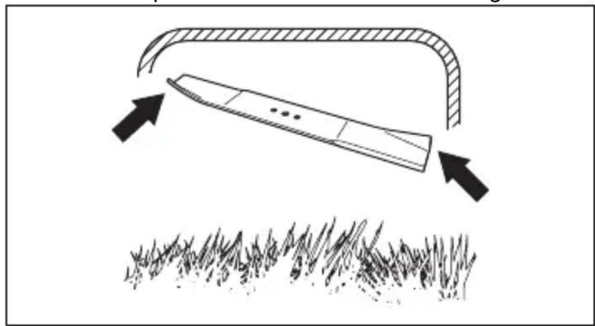
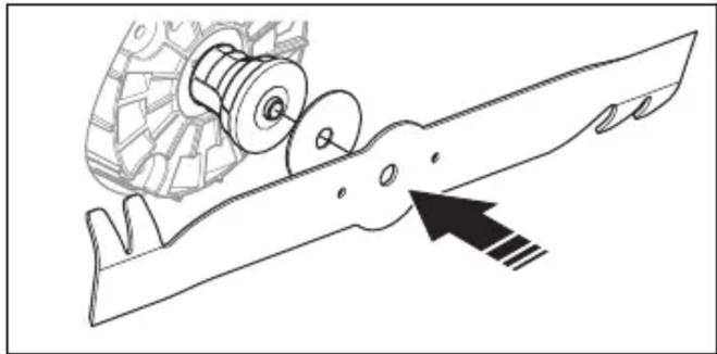
- Put the friction washer and the blade against the blade support.

- Make sure that the blade aligns with the center of the motor shaft.
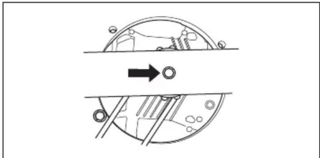
- Lock the blade with a block of wood.
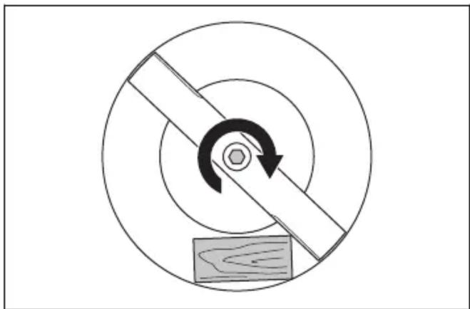
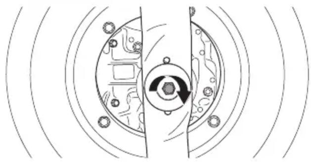
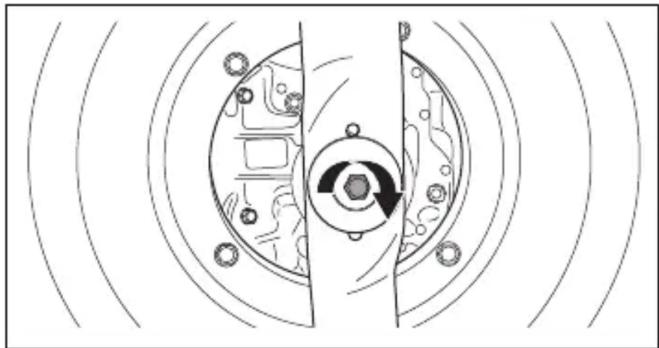
- Attach the spring washer and tighten the bolt with a torque of 65-75 Nm.
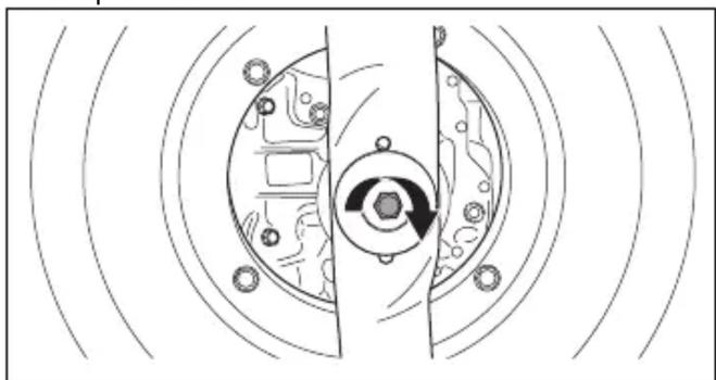
- Pull the blade around by hand and make sure that it turns freely.

WARNING: Use protective gloves.
The blade is very sharp and cuts can easily occur.
- Start the product to do a test of the blade. If the blade is not correctly attached, there is vibration in the product or the cutting result is unsatisfactory.
To clean the product
- Clean plastic parts with a clean and dry cloth.
- Do not use water to clean the product. Water can enter the battery or the motor and cause short circuit or damage to the product.
- Use a brush to remove leaves, grass and dirt.
- Remove the protection cover and use a brush to clean the inner side of the protection cover from grass.
To clean the battery and the battery charger

WARNING: Do not clean the battery or the battery charger with water.

WARNING: Do not use any chemical substances to clean the battery.
- Make sure that the battery and the battery charger are clean and dry before you put the battery into the battery charger.
- Clean the battery terminals with compressed air or use a soft and dry cloth.
- Clean the surfaces of the battery and the battery charger with a soft and dry cloth.
To examine the cutting equipment

WARNING: To prevent accidental start, pull up the safety key, remove the battery and wait a minimum 5 seconds.

WARNING: Use protective gloves when you do maintenance on the cutting equipment. The blade is very sharp and cuts can easily occur.
- Examine the cutting equipment for damage or cracks. Always replace a damaged cutting equipment.
- Look at the blade to see if it is damaged or blunt.
Note: It is necessary to balance the blade after it is sharpened. Let a service center sharpen, replace and balance the blade. If you hit an obstacle that causes the product to stop, replace the damaged blade. Let the service center estimate if the blade can be sharpened or must be replaced.
Troubleshooting
Battery
| LED on the battery Cause | Solution | |
| The green LED flashes. | The battery voltage is low. Charge the battery. | To charge the battery on page 21. |
| The error LED flashes. | The battery is weak. Charge the battery. | Refer to Battery on page 27. |
| The temperature in the work environment is too high or too low. | Use the battery in temperatures between -10°C and 40°C. | |
| Overvoltage. Make sure that the mains | voltage is the same as on the rating plate on the product. | |
| Remove the battery from the battery charger. Wait 5 seconds and try again to charge the battery. If the problem continues, speak to an approved service agent. | ||
| The error LED is on. The | cell difference too much (1V). Speak to | an approved service agent. |
Battery charger
| LED on the battery charger | Cause Solution | |
| The error LED flash-es. | The temperature in the work environment is too high or too low. | Use the battery charger in temperatures between 5°C and 40°C. |
| The error LED is on. S | Speak to an approved service agent. |
Control panel
| Error code (Number of flashes) | Possible faults Possible procedure | |
| 1 The transmission motor is too hot. Let the product become cool. Make sure that the transmission does not have grass on it. Clean the transmission cover if it is necessary. | ||
| 5 The motor speed decreases too much, and the motor stops. | Clean the cutting deck and increase the cutting height. Refer to To set the cutting height (LB 548i, LC 551iV) on page 20. If the error stays, speak to your approved service agent. | |
| 8 The battery is weak. | Charge the battery. Refer to | To charge the battery on page 21. |
| 9 Battery error or no signal from battery. Put the battery in the product | correctly and examine the battery connector. If the error LED on the battery flashes, refer to Battery on page 20. | |
| 10 The motor control is too hot. Stop the motor and wait until it is cool. | ||
| Other errors If other errors occur, remove the safety key and the battery and speak to an approved service agent. | ||
Transportation, storage and disposal
Introduction

WARNING: To prevent unintentional start during transport, pull up the safety key, remove the battery, and wait at least 5 seconds.
To set the product in transport position (LC 551iV)
- Loosen the lower knobs.
- Move the knobs to the lower end of the grooves on the left and right sides of the product.
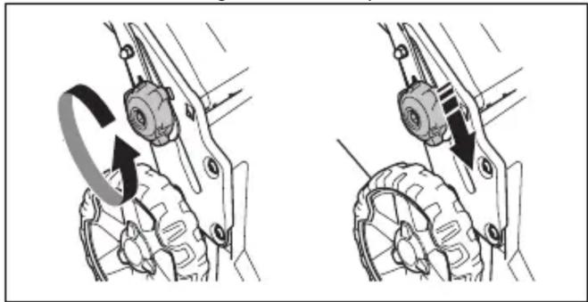
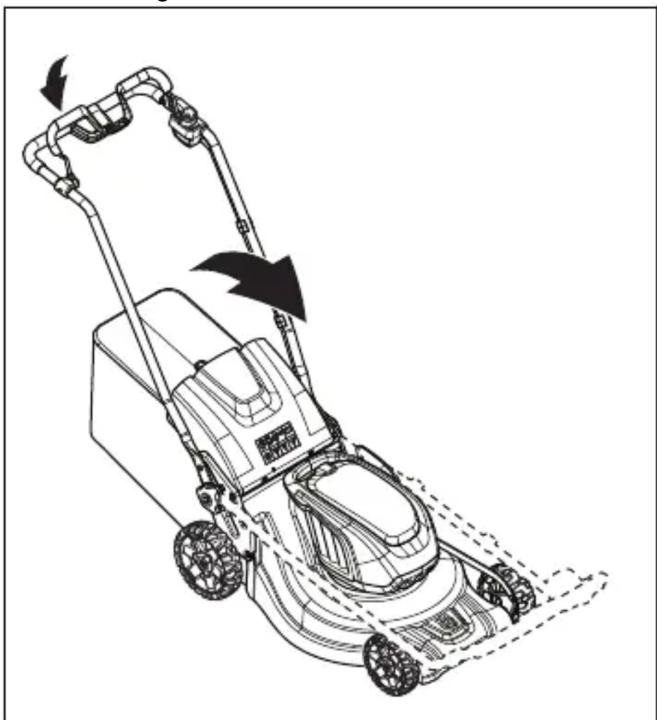
- Fold the handle forward.
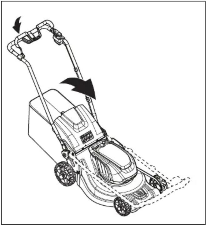
- Remove the grass catcher.
Transportation
- The Dangerous Goods Legislation requirements apply to the contained Li-ion batteries.
- For commercial transports, special requirements on package and labels must be obeyed.
- Make sure that you obey the regulations for dangerous material when you prepare the product for transport. Local regulations can apply. • Always remove the battery for transport.
- Put tape on the battery connectors and make sure that the battery cannot move around during transport.
- Attach the product during transport.
Storage
- Always remove the battery for storage.
- To prevent accidents, make sure that the battery is not connected to the product during storage.
- Keep the battery charger in a closed and dry space.
- Keep the battery and the battery charger in a dry space where there is no moisture or frost.
- Disconnect the battery from the battery charger during storage.
- Do not keep the battery where static electricity can occur. Do not keep the battery in a metal box.
- Keep the battery where the temperature is between 5°C and 25°C and out of sunlight.
- Keep the battery charger where the temperature is between 5°C and 45°C and out of sunlight.
- Make sure that the battery is charged to 30% - 50% before you put it in storage for long periods.
- Keep the product, battery, and battery charger in a locked area out of reach of children and unauthorized persons.
- Clean the product and perform complete servicing before storing it for a long period.
Disposal
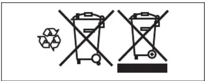
Symbols on the product or its packaging indicate that this product cannot be disposed of as household waste. It must be taken to an appropriate recycling facility for the recovery of electrical and electronic equipment.
By ensuring this product is disposed of correctly, you can help prevent potential negative impacts on the environment and human health that could otherwise result from improper waste handling. For more detailed information about recycling this product, contact your local municipality, your household waste disposal service, or the store where you purchased the product.
Technical data Technical data
| LB 548i LB 553iV LC 551iV | |||
| Cutting motor | |||
| Motor type BLDC (brushless) | 36V | BLDC (brushless)36V | BLDC (brushless)36V |
| Motor speed – SavE, rpm* 2600 2600 2600 | |||
| Motor speed – Nominal, rpm* 3000 3000 3000 | |||
| LB 548i LB 553iV LC 5 | 51iV | ||
| Motor speed – High load, rpm* 3300 3300 3300 | |||
| Motor output – max. kW 1.8 1.8 1.8 | |||
| Motor output – Nominal, kW 1.5 1.5 1.5 | |||
| Drive motor | |||
| Motor output – Nominal, kW N/A 0.4 0.4 | |||
| Self walk speed, km/h N/A 3.0–5.0 3.0–5.0 | |||
| Speed adjustment levels N/A 4 4 | |||
| Weight | |||
| Weight without battery, kg 31 38 39.5 | |||
| Battery | |||
| Type of battery Husqvarna Battery | Series | Husqvarna Battery Series | Husqvarna Battery Series |
| Battery runtime | |||
| Battery runtime, min, (free run) with SavE activated, with one Husqvarna 9.4 Ah battery (Bli300). | 35 35 30 | ||
| Battery runtime, min, (free run) with standard mode activated, with one Husqvarna 9.4 Ah battery (Bli300). | 30 30 25 | ||
| Noise emissions 1 | |||
| Sound power level, measured dB (A) 93 97 97 | |||
| Sound power level, guaranteed LWA dB (A) | 93 98 97 | ||
| Sound levels 2 | |||
| Sound pressure level at the operator's ear, dB (A) | 80 84 84 | ||
| Vibration levels 3 | |||
| Handle, m/s 2 | 0.3 1.3 0.3 | ||
| Cutting equipment | |||
| Cutting height, mm | 30-60 | 28-65 | 26-74 |
| Cutting width, cm | 48 53 51 | ||
| Blade standard | Mulch blade597466510 | Mulch blade529441810 | Collect blade597466310 |
| Blade accessory | N/A N/A Mulch blade | 597466410 | |
| LB 548i LB 553iV LC 551iV | ||
| Grass catcher capacity, I N/A N/A 65 |
* Revolutions per minute
| Approved batteries Type Battery capacity, | Ah | Voltage, V Weight, lb/kg |
| BLi20 Lithium-ion 4.0 36 2.6/1.2 | ||
| BLi200 Lithium-ion 5.2 36 2.8/1.3 | ||
| BLi300 Lithium-ion 9.4 36 4.1/1.9 | ||
| BLi550X Lithium-ion 15.6 36 12.4/5.6 | ||
| BLi950X Lithium-ion 31.1 36 15.4/7.0 |
| Approved chargers for the specified batteries, BLi Input voltage, V Frequency, Hz Power, W | |||
| QC80 | 100–240 50–60 | 80 | |
| QC80F | 12 | 0 | 80 |
| QC330 | 100–240 50–60 | 330 | |
| QC500 | 100–240 50–60 | 500 | |
Declaration of Conformity
EU Declaration of Conformity
We, Husqvarna AB, SE-561 82 Huskvarna, Sweden, tel: +46-36-146500, declare under our sole responsibility that the product:
| Description Lawn Mower | |
| Brand Husqvarna | |
| Type / Model LB 548i, | LC 551iV, LB 553iV |
| Identification Serial numbers dating from 2022 and onwards | |
complies fully with the following EU directives and regulations:
| Regulation Description | |
| 2006/42/EC "relating to machinery" | |
| 2014/30/EU "relating to electromagnetic compatibility" | |
| 2000/14/EC "relating to the noise emissions in the environment" | |
| 2011/65/EU | "on the restriction of the use of certain hazardous substances in electrical and electronic equipment" |
and that the following standards and/or technical specifications have been applied: EN 60335-1:2012/AC:2014/A11:2014/A13:2017, EN 60335-2-77:2010, EN 62233:2008/AC:2008, EN 55014-1:2017/A11:2020, EN 55014-2:2015, EN IEC 63000:2018
Notified Body: 0404, RISE SMP Svensk Maskinprovning AB, Box 4053, SE-904 03 Umeå, Sweden, has certified conformity with the Council's Directive 2000/14/EC, conformity assessment procedure: Annex VI.
For information relating to noise emissions, refer to Technical data on page 29.
Huskvarna, 2022-10-14
Claes Losdal, Development Manager/Garden Products Husqvarna AB
Responsible for technical documentation

UK Declaration of Conformity
We, Husqvarna AB, SE-561 82 Huskvarna, Sweden, tel:
+46-36-146500, declare on our sole responsibility that
the product:
| Description Lawn Mower | |
| Brand Husqvarna | |
| Type / Model LB 548i, LC 551iV, LB 553iV | |
| Identification Serial numbers dating from 2022 and onwards | |
complies fully with the following UK regulations:
| Description |
| The Restriction of the Use of Certain Hazardous Substances in Electrical and Electronic Equipment Regulations 2012 |
| The Supply of Machinery (Safety) Regulations 2008 |
| The Noise Emission in the Environment by Equipment for use Outdoors Regulations 2001, schedule 9 |
| Electromagnetic Compatibility Regulations 2016 |
and that the following standards and/or technical specifications are applied: EN 60335-1:2012/AC:2014/A11:2014/A13:2017, EN 60335-2-77:2010, EN 62233:2008/AC:2008, EN 55014-1:2017/A11:2020, EN 55014-2:2015, EN IEC 63000:2018
Notified Body: 0404, RISE SMP Svensk Maskinprovning AB, Box 4053, SE-904 03 Umeå, Sweden, has certified conformity with the council's directive 2000/14/EC, conformity assessment procedure: Annex VI.
For information relating to noise emissions, refer to Technical data on page 29.
Huskvarna, 2022-10-14
Claes Losdal, Development Manager/Garden Products Husqvarna AB
Responsible for technical documentation

UK Importer:
Husqvarna UK Ltd
Preston Road, Co. Durham
DL5 6UP
Contents


Technical data
- Insert the multi-battery into the battery adapter.
- Connect the multi-battery to the battery adapter.


Technical data
Technical data
- Open the battery cover.
- Remove the battery from battery compartment 1.
- Remove the seal stopper.
- Attach the multi-battery to the battery adapter.
- Connect the multi-battery to the battery adapter.


- Press the + and - buttons on the control panel to set the drive speed.
To move the product with the cutting equipment disabled (LB 553iV)
- Make sure the blade is aligned with the center of the motor shaft.
Technical data
*Revolutions per minute Technical data
Operations (Noise Control)
Regulation 2017"
(Environmental protection/


Technical specifications
Technical data




Technical data Technical data
- Place the adapter plate on the motor cover.
- Secure the adapter plate with four screws, using a torque of 5-6 Nm.
- Open the battery cover.
- Remove the battery from compartment 1.
- Remove the seal.
- Route the adapter cable through the seal's opening. Secure the cable with the clamp.
- Install the multi-battery onto the adapter.
- Connect the multi-battery to the adapter.
Assembly of the mulching plug (LC 551iV accessory)
- Remove the sensor.
- Attach the battery to the sensor. The sensor LED lights up.
- Download the Husqvarna Fleet Services TM app.
- Log in to the Husqvarna Fleet Services TM app.
- Pairing procedure See the section Pairing procedure between the app and the product. Page 248
Note: Make sure the holes have diameters that match the rivets supplied with the sensor.
- Align the sensor holder with the mounting bracket.

- Attach the sensor holder with the rivets.
- Install the sensor in the sensor holder. Align the white mark on the sensor with the mark on the sensor holder.


Towing on wheels (LC 551iV)
- Attach the spring washer and tighten the bolt to a torque of 65-75 Nm.
Technical data
Technical data
- Install the multi-battery into the battery adapter.
- Connect the multi-battery to the battery adapter.

NOTE: Do not place

NOTE: Do not place
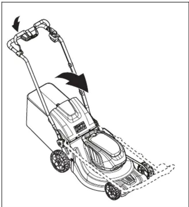
- Fold the handle forward.
Disposal
Warning: projectiles and ricochets.


- Control panel
- Engine brake handle
- Starting lock
- Grass catcher (LC 551iV)
- Rear cover (LC 551iV)
- Safety key
- Steering wheel (LC 551iV)
- Handle adjustment lever (LB 548i)
- Battery cover
- Cutting height control (LC 551iV)
- ON/OFF button
- SavE button
- SavE indicator
- Battery indicator
- Speed level indicator
- Speed decrease button
- Speed increase button
- LED error indicator
- Blade cover
- Air guide
- Protective cover (LC 551iV)
- Rating plate
- Drive lever (LC 551iV)
- Battery charger (accessory)
- Battery (accessory)
- Multi battery (accessory)
- Adapter plate (accessory)
- Multi battery adapter (accessory)
- Shredding kit (LC 551iV)
- User manual
Product overview (LB 553iV)
- Control panel
- Engine brake lever
- Start interlock
- Safety key
- Handle adjustment lever
- Battery cover
- Cutting height control
- ON/OFF button
- Save button
- Save indicator
- Battery indicator
- Speed level indicator
- Speed decrease button
- Speed increase button
- Error LED indicator
- Blade cover
- Air intakes
- Protective cover
- Rating plate
- Drive control handle
- Battery charger (accessory)
- Battery (accessory)
- Multi battery (accessory)
- Adapter plate (accessory)
- Multi battery adapter (accessory)
- User manual
Symbols on the product

WARNING: This product can be dangerous and cause serious injury or death
to the operator or others. Be careful and use this product properly.

DANGER – keep hands and feet away.
Product reliability
Start interlock check
- Place the adapter plate on the engine cover.
- Attach the adapter plate using the 4 supplied screws and tighten them to a torque of 5 – 6 Nm.
- Open the battery cover.
- Remove the battery from slot 1.
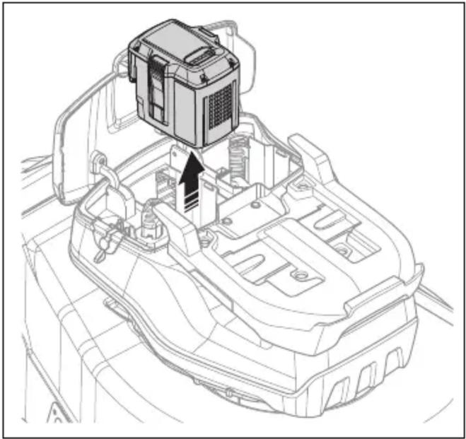
- Remove the seal limiter.
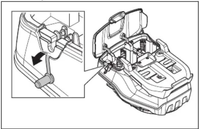
- Press the battery adapter into the battery compartment until you hear a click.
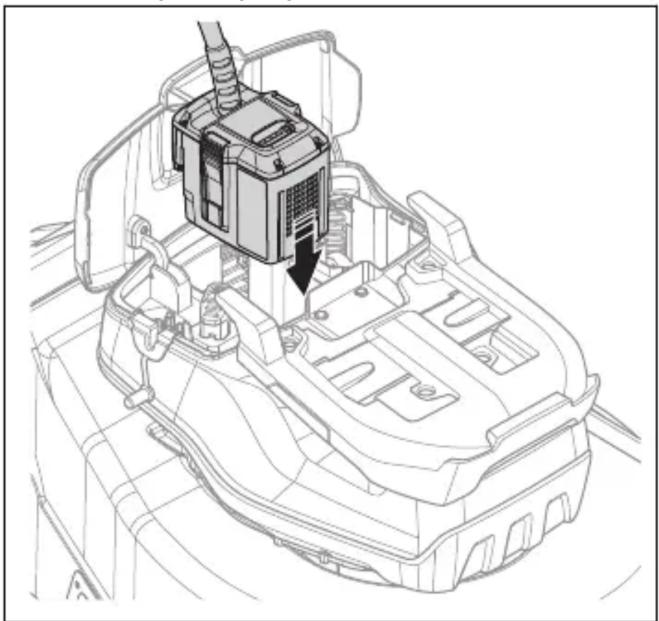
- Thread the battery adapter cable through the hole in the seal limiter. Secure the cable with the clip.
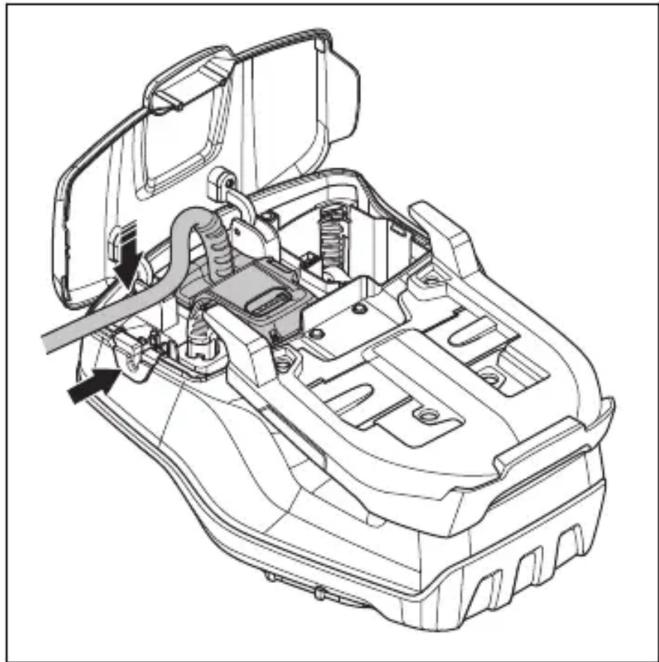
- Install the multi-battery onto the battery adapter.
- Connect the multi-battery to the battery adapter.
- Secure the battery adapter cable to the handle using the 3 fabric straps.
- Set the handle height to one of the two available positions.
- Move the wheels up towards the handle until they stop with a click.
- When working with the product near a wall, turn the handle to the side suitable for the work.
Mounting the grass collector (LC 551iV)
Assembling the mulching plug (LC 551iV optional equipment)
- Remove the sensor.
- Connect the battery to the sensor. The sensor LED will turn on.
- Download the Husqvarna Fleet Services TM app.
- Log in to the Husqvarna Fleet Services TM app.
- Perform the pairing. Read the section Pairing the app with the product on page 342.
Pairing the app with the product
Note: Make sure that the two holes are the same size as the rivets supplied with the sensor.
- Use pliers to remove the outer holes on the sensor slot.
- Drill 2 holes at the marks on the sensor slot.
- Attach the sensor slot with rivets.
- Install the sensor in the sensor slot. Align the white mark on the sensor with the mark on the sensor slot.


- Place the battery in the battery charger. If the battery is correctly connected to the battery charger, a green indicator lights up on the charger.
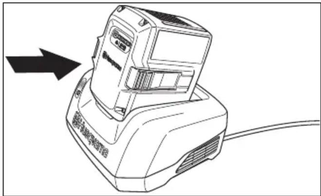
- When all LED indicators on the battery are lit, the battery is fully charged. Charge the battery for a maximum of 24 hours.
- To disconnect the battery charger from the wall outlet, pull the plug, not the cable.
- Remove the battery from the battery charger.
Battery charger status
The Husqvarna lithium-ion battery can be charged or used at any charge level. The battery is not damaged. A fully charged battery will not discharge when left in the charger.
| LED zaslon | Stanje punjenja |
| Indikator LED 1 treperi 0% | -25% |
| Svijetli indikator LED 1, indikator LED 2 treperi | 25% – 50% |
| Svijetle indikatori LED 1, LED 2, indikator LED 3 treperi | 50% – 75% |
| Svijetle indikatori LED 1, LED 2, LED 3, indikator LED 4 treperi | 75% – 100% |
| Svijetle indikatori LED 1, LED 2, LED 3 i LED 4 | Potpuno napunjena |
Charging the multi-battery
Note: Charge the battery before first use. A new battery is only 30% charged.
- Make sure the battery is dry.
- Connect the multi-battery to the adapter.
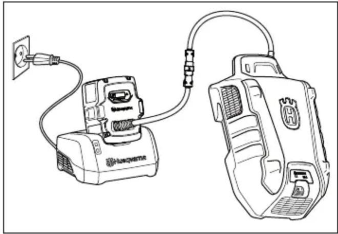
- Place the adapter on the battery charger.
- Check whether the green charging LED indicator on the battery charger lights up. This means that the adapter is correctly connected to the multi-battery.
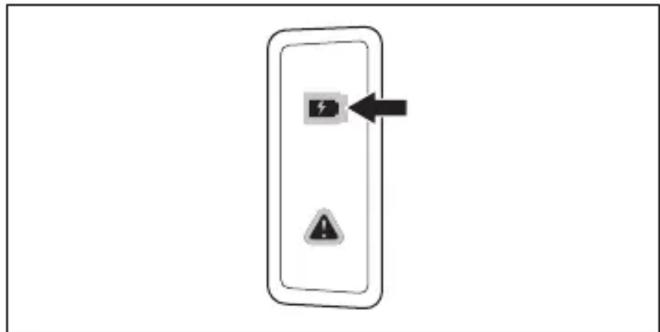
- When all LED indicators on the battery light up and the adapter shows 100%, the battery is fully charged.
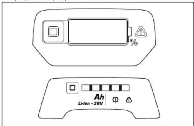
The adapter displays the state of charge in 1% increments. At the beginning of charging, slight deviations are possible.
- To disconnect the battery charger from the mains socket, pull out the plug. Do not pull the cable.
- Remove the adapter from the battery charger.
- Remove the multi-battery from the adapter.
Note: For more information, refer to the manuals for the multi-battery and battery charger.
- Stand behind the product.
- Press the ON/OFF button on the control panel. The display turns on.
- Release the start lock.
Using the wheel drive (LC 551iV)
- Press + and - on the control panel to set the drive speed in 4 steps.
Moving the product with the cutting equipment switched off (LB 553iV)
- Engage the start interlock.
- Pull the drive control handle upward.
- Hold the drive control handle and move the product.
- To continue working, release the drive control handle and disengage the start interlock.
Using the SavE function
The product has a battery saving function (SavE) that enables longer operating time.
- Press the SavE button (A) to activate the function. The SavE symbol (B) appears on the display.
- Press the SavE button again to stop the function. The SavE symbol (B) disappears from the display.

- Press the ON/OFF button on the control panel. All LED indicators and symbols on the display turn off.
- Remove the blade screw, spring washer, and blade.
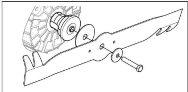
- Place the friction washer and blade on the blade holder.
- Install the elastic split ring and tighten the screw to a torque of 65-75 Nm.




Technical data
Inspection of the start inhibitor device
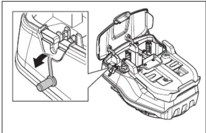
- Remove the seal stop.


- Lock the blade with a wooden block.
- Fold the handle forward.
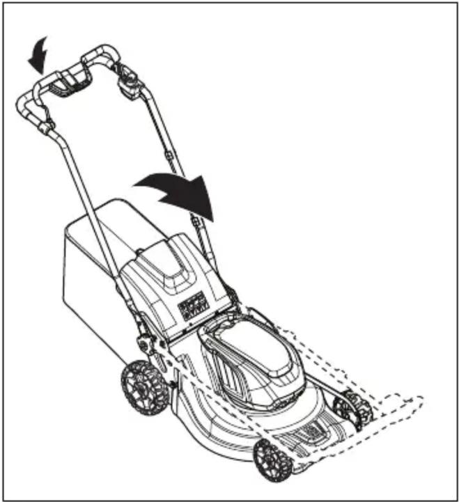
- Remove the grass catcher.
Transport
Main specifications
* Revolutions per minute Main specifications
- Pull out the plug.


The adapter shows the charge level in 1% increments.
How to move with the product when the cutting equipment is disconnected (LB 553iV)
- Turn the blade by hand and check that it rotates freely.

Technical data
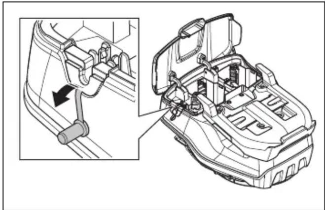
- Open the battery compartment.
- Remove the battery from slot 1.
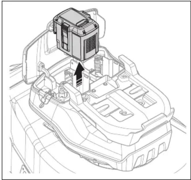
- Remove the gasket retainer.
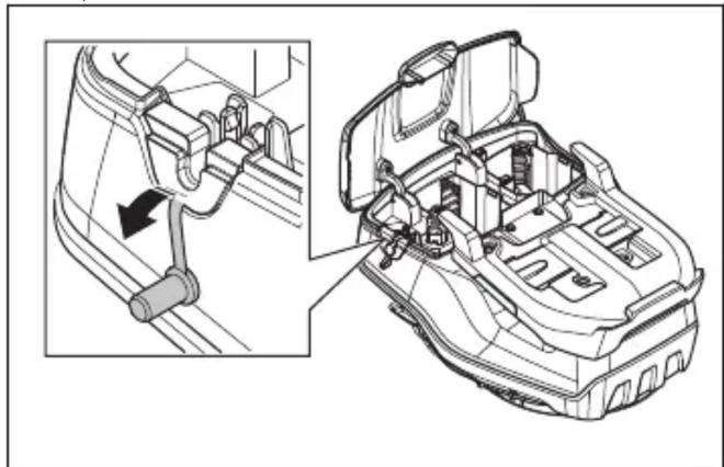
- Route the battery adapter cable through the gasket retainer opening. Connect the cable with the clamp.
- Install the multi-battery onto the battery adapter.
- Connect the multi-battery to the battery adapter.
- Secure the battery adapter cable to the handle with 3 fabric straps.
- Remove the sensor.
- Attach the battery to the sensor. The sensor LED lights up.
- Align the sensor slot with the housing slot.


- Remove the blade screw, spring, remove the washer and blade.
- Place the friction washer and blade against the blade support.
- Attach the spring washer and tighten the screw to a torque of 65-75 Nm.
Technical data Technical data
Install the grass catcher (LC 551iV)
Install the mulching plug (accessory LC 551iV)


| LED-lampjes Accustatus | |
| Alle leds branden Volledig opgeladen (75-100%) | |
| Led 1, led 2, led 3 branden | De accu is 50%-75% op-geladen |
| Led 1, led 2 branden De accu is 25%-50% op-geladen | |
| Led 1 brandt De accu is 0%-25% opge-laden. | |
| LED 1 knippert De accu is leeg. Laad de accu op. | |
Charge the battery
| LED-display | Laadstatus |
| LED 1 knippert 0%-25% | |
| Led 1 brandt, led 2 knip-pert | 25%-50% |
| Led 1 en led 2 branden, led 3 knippert | 50%-75% |
| Led 1, led 2 en led 3 bran-den, led 4 knippert | 75%-100% |
| Led 1, led 2, led 3, led 4 branden | Volledig opgeladen |
Charge the multi-battery
- Check the blade support and blade bolt for damage.
Technical data
Technical data
Claes Losdal, Development Manager/Garden Products, Husqvarna AB
- Place the adapter plates on the motor cover.
- Secure the adapter plates with the four supplied screws at a torque of 5-6 Nm.
- Remove the sealing plug.
- Attach the multi-battery to the battery adapter.
- Connect the multi-battery to the battery adapter.
How to install the fine distribution plug (LC 551iV accessory)
- Replace the blade with the fine distribution blade included in the fine distribution kit. See How to replace the blade on page 569.
Operation
Introduction

WARNING: Before using the product, you must read and understand the safety chapter.
Husqvarna Connect
Husqvarna Connect is a free app for your mobile device. The Husqvarna Connect app provides extended features for your Husqvarna product:
How to set the product in working position (LC 551iV)


- Insert the battery into the battery charger. The green light on the charger turns on when the battery is correctly connected to the charger.
- When all LED indicators on the battery are lit, the battery is fully charged. Charge the battery for a maximum of 24 hours.
- To disconnect the charger from the wall outlet, pull on the plug itself, not the cord.
- Remove the battery from the battery charger.
Battery charging status
A Husqvarna Li-ion battery can be charged or used at any charge level. The battery will not be damaged. The charge level of a fully charged battery does not decrease when the battery is left in the charger.
| LED-display | Ladestatus |
| LED 1 blinker 0–25 % | |
| LED 1 lyser, LED 2 blinker | 25–50 % |
| LED 1, LED 2 lyser, LED 3 blinker | 50–75 % |
| LED 1, LED 2, LED 3 ly-ser, LED 4 blinker | 75–100 % |
| Lampe 1, lampe 2, lampe 3 og lampe 4 tennes | Fulladet |
How to charge the multi-battery
- Insert the adapter into the battery charger.
- Make sure that the green charging light on the charger turns on. This means that the adapter and the multi-battery are correctly connected.
- When all LED indicators on the battery light up and the adapter shows 100%, the battery is fully charged.
- Stand behind the product.
- Press the ON/OFF button on the control panel. The display turns on.
- Release the start interlock.
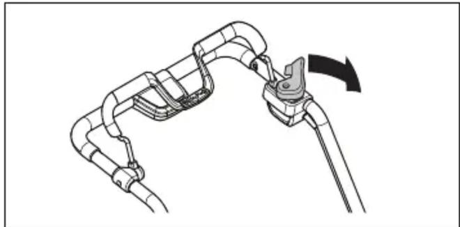
- Push the drive lever down to disengage the drive, for example when you are near an obstacle.
- Press the ON/OFF button on the control panel. All LED lights and symbols on the display turn off.
- Remove the blade bolt, the spring washer, and the blade.
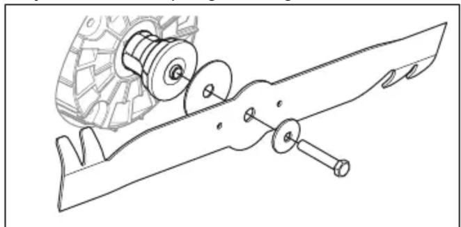
- Check the blade support and the blade bolt for damage.
- Attach the spring washer, and tighten the bolt to a torque of 65-75 Nm.

- Tilt the machine forward.
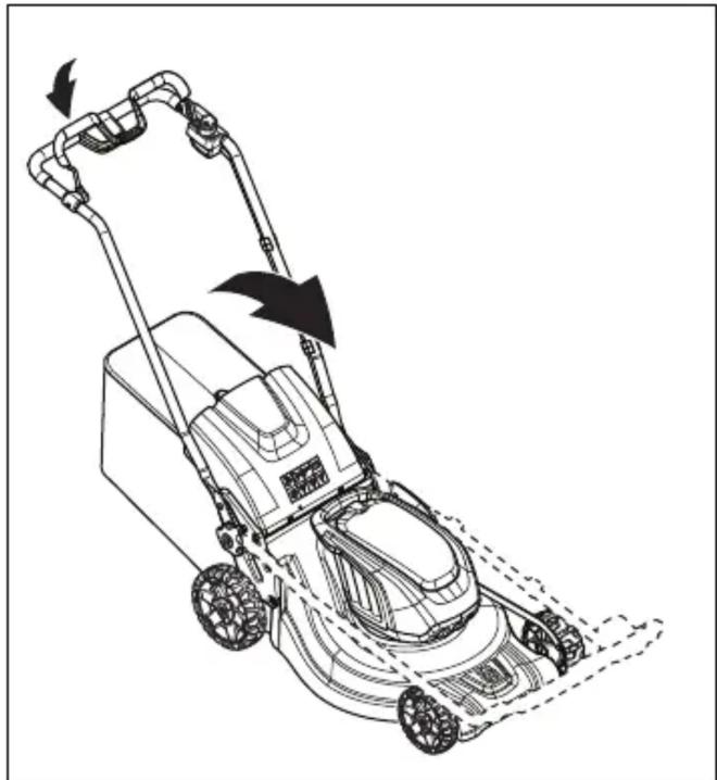
- Empty the collector.
Transport
- Extended product information. • Information about, and help with, product parts and servicing.


Technical data
Technical data
Check the start inhibitor
Check the start inhibitor to make sure it prevents the engine from starting.
- Install the multiple battery in the battery adapter.
- Connect the multiple battery to the battery adapter.
Mount the grass collector (LC 551iV)
- Align the sensor slot with the housing slot.
- Secure the sensor slot with the rivets.
- Install the sensor in the sensor slot. Align the white mark on the sensor with the mark on the sensor slot.




Technical data Technical data


Technical data
Technical data
Check the start-up fuse
- Push the battery adapter into the battery compartment until it clicks.
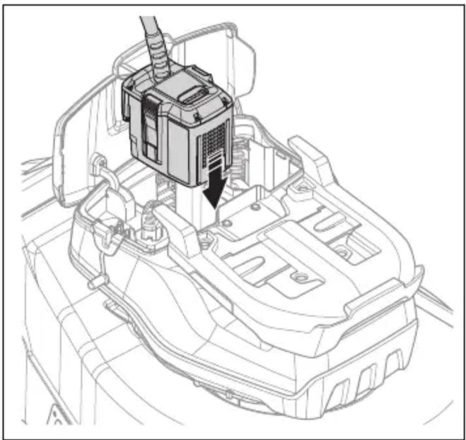
- Thread the battery adapter cord through the hole in the sealing plug. Secure the cord with the clip.
- Install the multi-battery onto the battery adapter.
- Connect the multi-battery to the battery adapter.
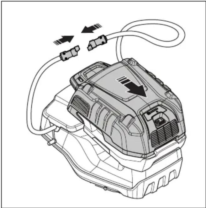
- To remove the multi-battery, follow the same steps in reverse order.

- Drill 2 holes according to the marks in the sensor slot.
- Slide the buttons upward toward the handle until they stop and you hear a click.
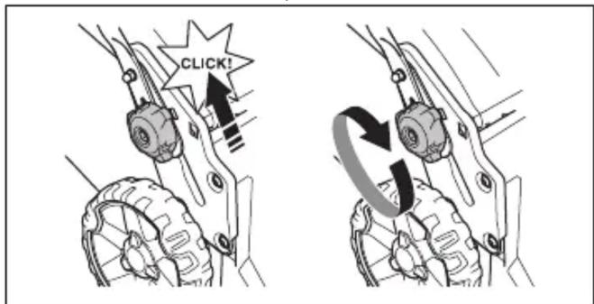
- Tighten the buttons to the stop.


- When all LED indicators on the battery are lit, the battery is fully charged. Charge the battery for a maximum of 24 hours.
- When disconnecting the battery charger from the wall outlet, pull on the plug, not the cord.
- Remove the battery from the battery charger.
Battery charging status
- Insert the adapter into the battery charger.
- Make sure the green LED charging indicator on the battery charger lights up. This means that the adapter and the multi-battery are correctly connected.
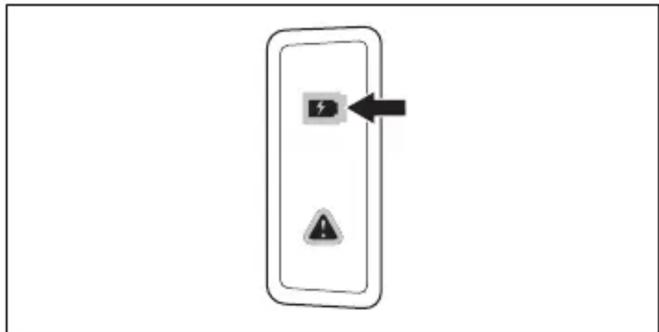
- When all LEDs on the battery are lit and the adapter shows 100%, the battery is fully charged.
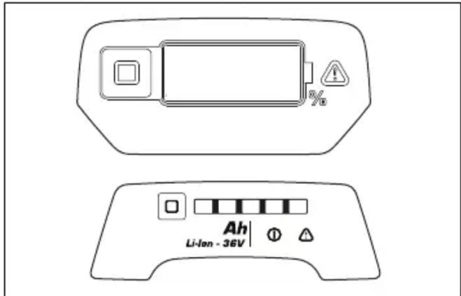
- Press the ON/OFF button on the control panel. All LEDs and symbols on the display will turn off.
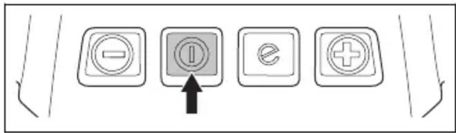
- Remove the blade screw, spring washer, and blade.
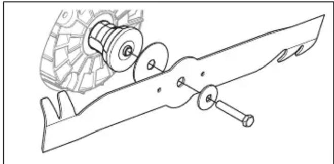
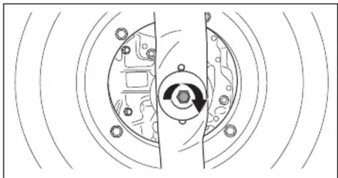
- Attach the spring washer and tighten the screw to a torque of 65-75 Nm.
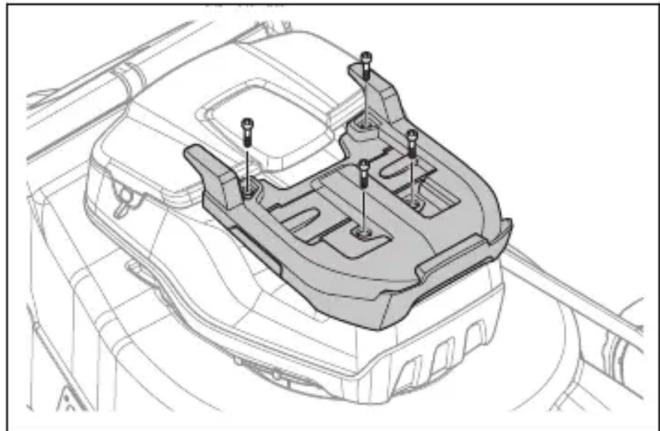
- Place the intermediate plate on the engine cover.
- Attach the intermediate plate with the 4 supplied screws, tightening to 5–6 Nm.
- Push the battery adapter into the battery compartment until it clicks into place.
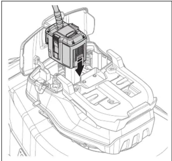
- Install the battery pack onto the battery adapter.
- Connect the battery pack to the battery adapter.
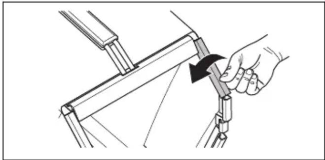
- Insert the lower part of the grass catcher frame into the groove on the bottom of the grass catcher.
- Fit the grass bag over the grass catcher frame and secure it with the clips.
- Replace the blade with the mulching blade supplied with the mulching kit. See Replacing the blades on page 764.
Operation
Introduction

WARNING: Before using the product, you must read and understand the safety chapter.
Husqvarna Connect
- Remove the sensor.
- Connect the sensor to the battery. The sensor indicator must light up.

WARNING: Do not set the cutting height too low. The blades may hit the ground if the lawn surface is uneven.
Setting the cutting height (LB 553iV)

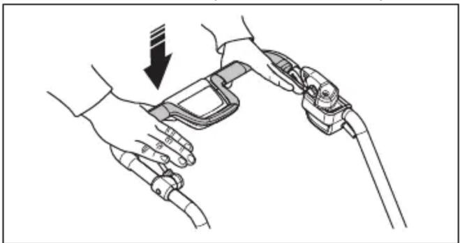
- Push the engine brake lever towards the handle.
For wheel drive (LC 551iV)
Moving the product with the cutting equipment switched off (LB 553iV)
- Remove the blade screw, spring washer, and blade.
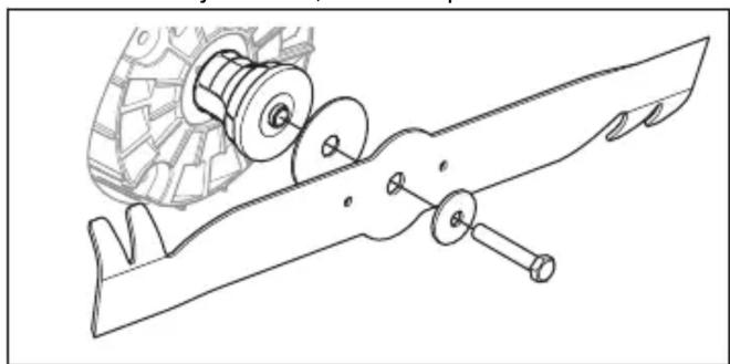
- Check that the blade holder and blade screw are not damaged.
- Install the friction washer and blade on the blade holder.
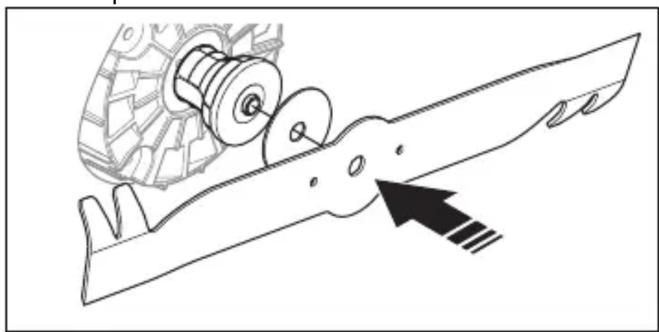
- Attach the spring washer and tighten the screw with a torque of 65-75 Nm.
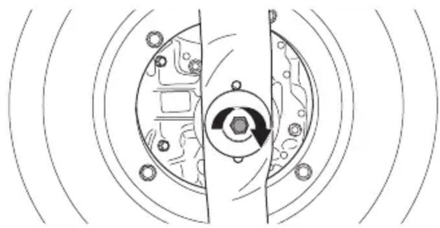
- Rotate the blade by hand and make sure it turns freely.

- Remove the grass catcher.
Transport
Technical data
Technical data
- Control panel
- Engine brake lever
- Starting inhibitor
- Grass catcher (LC 551iV)
- Rear cover (LC 551iV)
- Safety key
- Handle button (LC 551iV)
- Handle adjustment lever (LB 548i)
- Battery cover
- Cutting height adjustment (LC 551iV)
- ON/OFF button
- Save button
- Save indicator
- Battery indicator
- Speed level indicator
- Speed decrease button
- Speed increase button
- Error LED light
- Mowing cover
- Air intakes
- Protective cover (LC 551iV)
- Rating plate
- Drive pusher (LC 551iV)
- Battery charger (equipment)
- Battery (accessory)
- Multi battery (accessory)
- Adapter plate (accessory)
- Multi battery adapter (accessory)
- Mulching kit (LC 551iV)
- Operator's manual
Product overview (LB 553iV)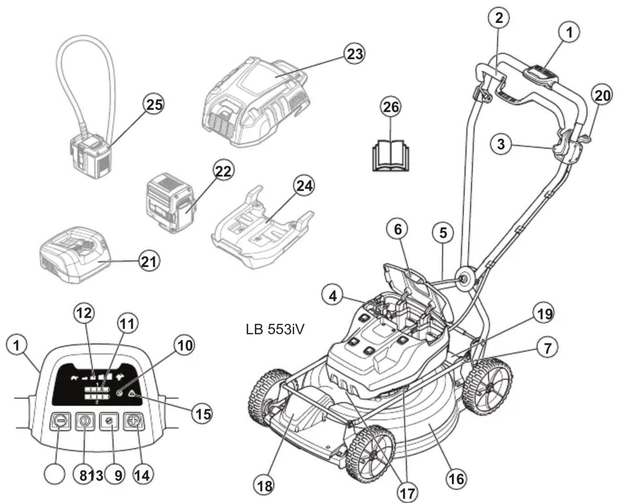
- Control panel
- Engine brake lever
- Start inhibitor
- Safety key
- Handle adjustment lever
- Battery cover
- Cutting height control
- ON/OFF button
- Save button
- Save indicator
- Battery indicator
- Speed level indicator
- Speed decrease button
- Speed increase button
- Error LED light
- Mowing cover
- Air intakes
- Protective cover
- Rating plate
- Drive control lever
- Battery charger (accessory)
- Battery (accessory)
- Multi battery (accessory)
- Adapter plate (accessory)
- Multi battery adapter (accessory)
- User manual
Symbols on the product

WARNING: This product can be dangerous and cause serious injury or death
to the operator or other persons. Be careful and use the product properly.

Before using the product, carefully read the user manual and make sure you understand it.

Make sure that people and animals are at a safe distance from the work area.

Watch out for thrown objects and ricochets.
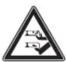
Warning: Keep hands and feet away from the rotating blade.

Warning: Keep hands and feet away from rotating parts.
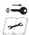
DANGER – keep hands and feet away.
Starting inhibitor check
Perform the starting inhibitor check to ensure it prevents the engine from operating.
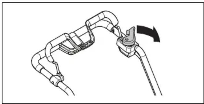
- Press the engine brake lever toward the handlebar. The starting inhibitor stops movement.
- Press the starting inhibitor outward.
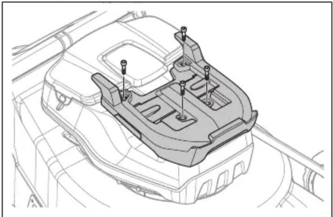
- Place the adapter plate on the engine cover.
- Secure the adapter plate using the 4 provided screws to a tightening torque of 5–6 Nm.
- Open the battery cover.
- Remove the battery from compartment 1.
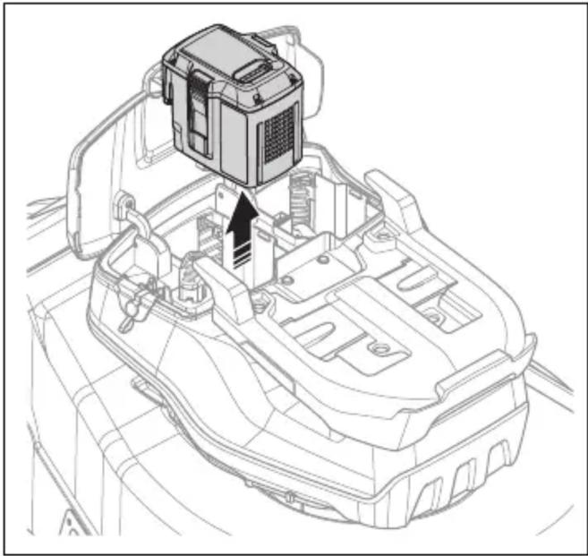
- Press the battery adapter into the battery compartment until you hear a click sound.
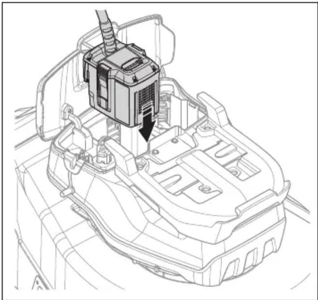
- Route the battery adapter cable through the opening of the sealing limiter. Secure the cable with the clamp.
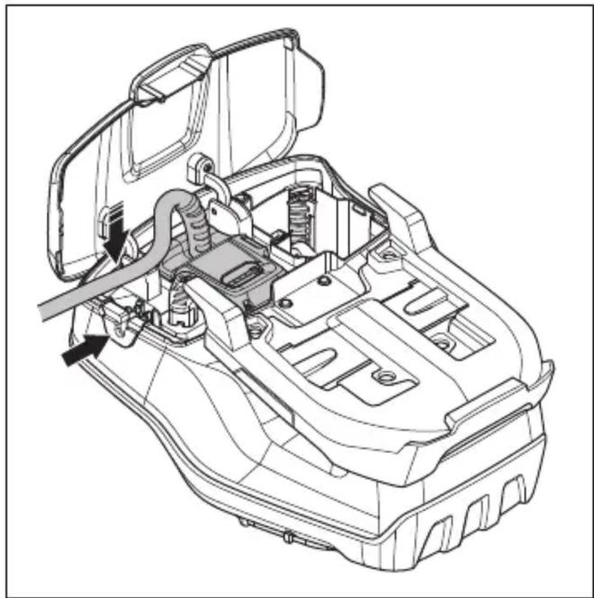
- Place the multi-battery on the battery adapter.
- Connect the multi-battery to the battery adapter.
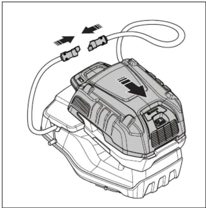
- Remove the multi-battery in reverse order.

WARNING: Do not attach the cable too loosely to the handle. The cable may fall off the handle and cause injury.
Adjusting the handle (LC 551iV)
- Loosen the lower buttons.
- Move the buttons to the lower end of the grooves on the left and right sides of the product.
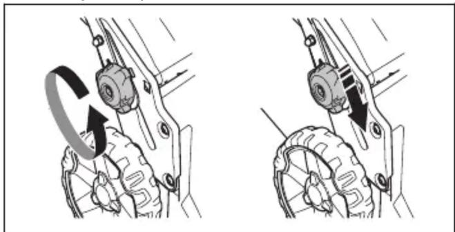
- Place the handle in one of the 2 height positions.
- Move the buttons upward in the direction of the handle until they stop and you hear a click sound.
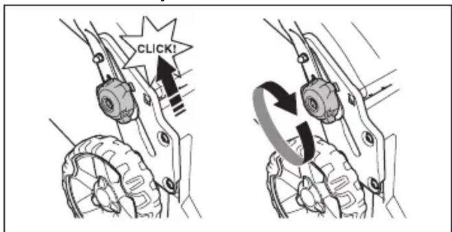
- Tighten the buttons completely.
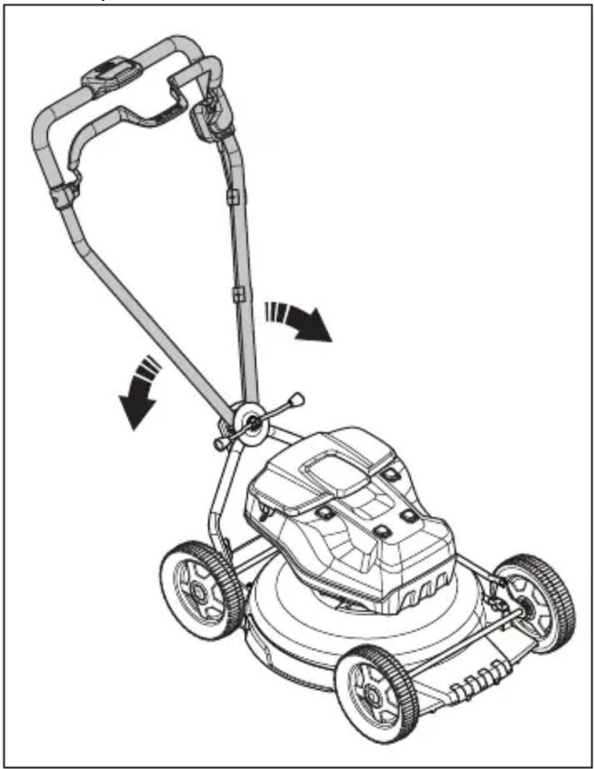
Folding the handle (LB 548i, LB 553iV)
- Turn the handle to the side for a good working position when using the product near a wall.
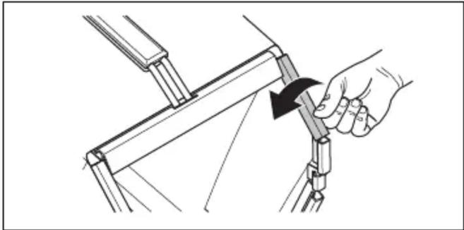
Folding the grass catcher (LC 551iV)
- Place the lower part of the grass catcher frame into the groove at the bottom of the grass catcher.
- Attach the grass bag frame with the connectors.
Installing the mulching attachment (LC 551iV equipment)
- Replace the blade with the mulching blade from the mulching kit. See Replacing the blade on page 796.
Operation
Introduction

- Remove the sensor.
- Connect the battery to the sensor. The sensor LED lights up.
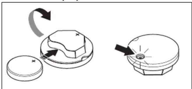
- Download the Husqvarna Fleet Services™ app.
- Log in to the Husqvarna Fleet Services™ app.
- Perform the pairing process. See Performing the pairing process between the app and the product on page 789.
Performing the pairing process between the app and the product.
- Log in to the Husqvarna Fleet Services™ app.
- Select the product in the app.
- Use your mobile device to scan the code located behind the sensor to install the sensor in the app.
Note: The pairing process between the app and the product only needs to be done once.
Installing the sensor
- Make sure the sensor is connected to the Husqvarna Fleet Services™ app. See Performing the pairing process between the app and the product on page 789.
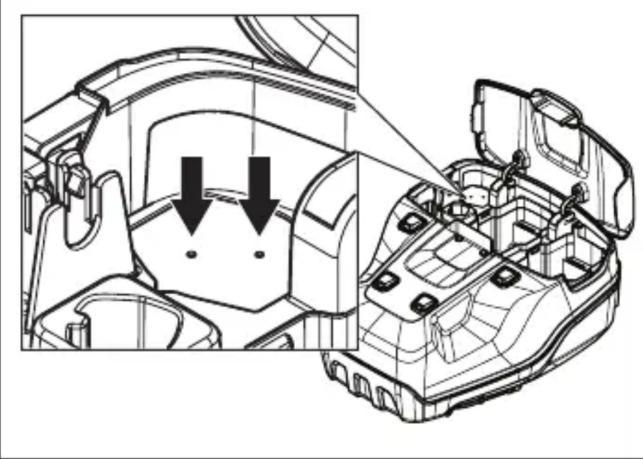
- Drill 2 holes next to the markings in the housing opening.
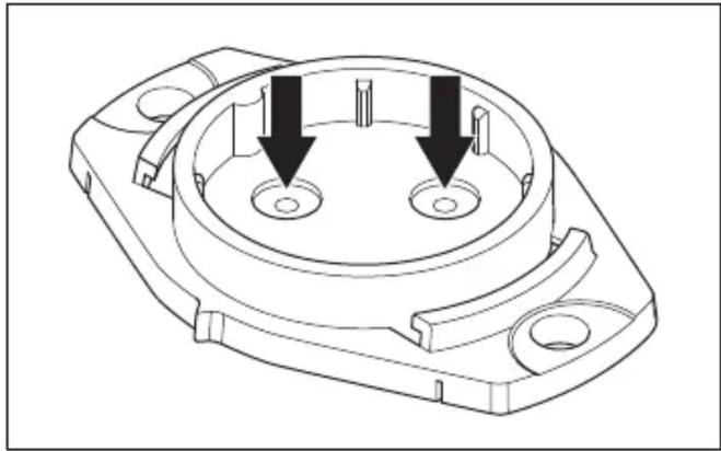
- Drill 2 holes next to the markings in the sensor slot.
- Attach the sensor slot using rivets.
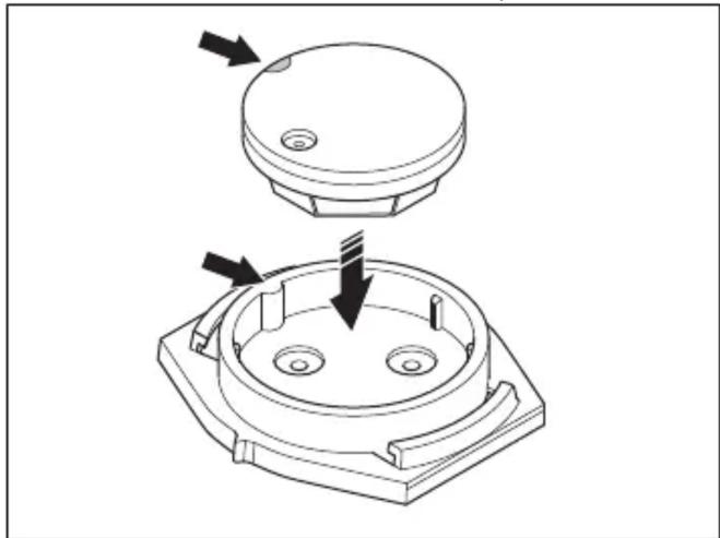
- Place the sensor in the sensor slot. Align the white mark on the sensor with the mark on the sensor slot.
- Move the buttons upward toward the handle until they stop and you hear a click sound.
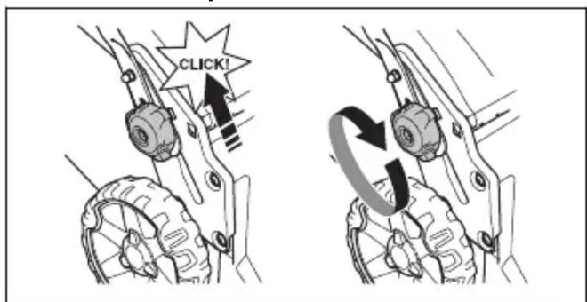
- Tighten the buttons fully.
Adjusting the cutting height (LB 548i, LC 551iV)
The cutting height can be adjusted in 6 levels.
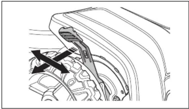
- Push the cutting height control toward the wheel and then backward to increase the cutting height.
- Set the cutting height in the direction of the wheel and reduce the cutting height in advance.


- The battery is fully charged when all LED lights on it are lit. Charge the battery for a maximum of 24 hours.
- To disconnect the battery charger from the wall outlet, pull the plug, not the power cord.
- Remove the battery from the battery charger.
Battery charging status
The Husqvarna lithium-ion battery can be charged or used at all charge levels. The battery is not damaged. A fully charged battery will not lose charge when left on the charger.
| LED displej | Status punjenja |
| LED br. 1 trepće 0%-25% | |
| LED br. 1 svetli, LED br. 2 trepće | 25%-50% |
| LED br. 1, LED br. 2 svet-le, LED br. 3 trepće | 50%-75% |
| LED br. 1, LED br. 2, LED br. 3 svetle, LED br. 4 trepće | 75%-100% |
| LED br. 1, LED br. 2, LED br. 3, LED br. 4 svetle | Potpuno napunjeno |
Charging the multi-battery
Note: Charge the battery if it is the first time it is used. A new battery is only charged to 30%.
- Make sure the battery is dry.
- Connect the multi-battery to the adapter.
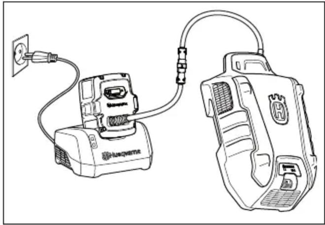
- Place the adapter into the battery charger.
- Check that the green charging LED on the battery charger is lit. This means that the adapter and multi-battery are correctly connected.
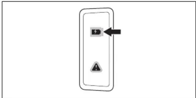
- When all LED lights on the battery are lit and the adapter shows 100%, the battery is fully charged.
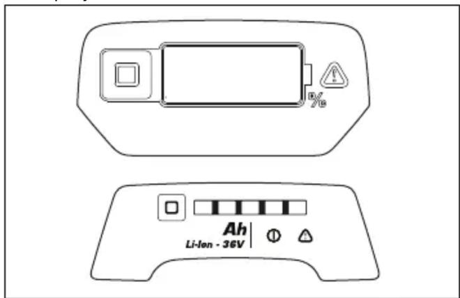
The adapter displays the state of charge in 1% increments. Minor deviations may occur at the beginning of charging.
- To disconnect the battery charger from the mains socket, pull the plug. Do not pull the cable.
- Remove the adapter from the battery charger.
- Remove the multi-battery from the adapter.
- Stand behind the product.
- Press the ON/OFF button on the control panel. The display lights up.
- Release the start inhibitor.
Using the wheel drive (LC 551iV)
- Pull the drive shaft in the direction of the handle to engage the drive.
- Press + and - on the control panel to set the drive speed in 4 steps.
- Release the drive lever to disengage the drive, for example, when near an obstacle.
Using the wheel drive (LB 553iV)
- Start the product, see Starting the product on page 792.
- Pull the drive control lever up to start the drive.
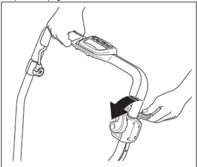
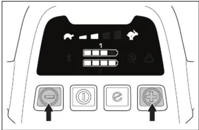
- Press the + and – buttons on the control panel to set the drive speed.
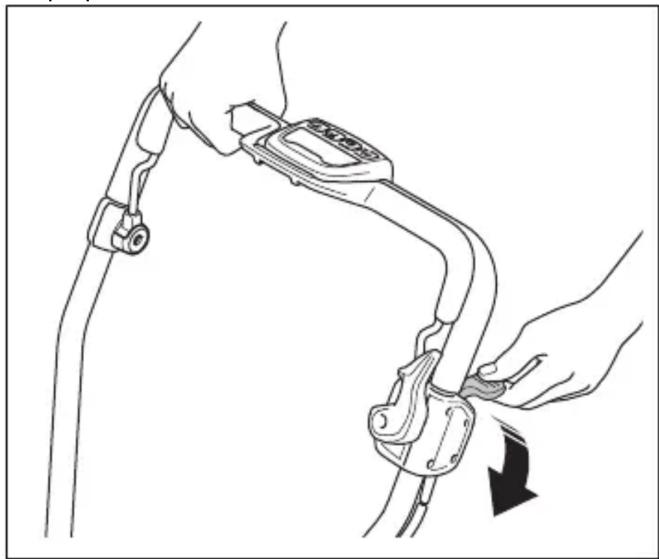
- Push the drive control lever down to deactivate the drive, for example, when you are near an obstacle.
Moving the product with the cutting equipment deactivated (LB 553iV)
- Activate the start inhibitor.
- Pull the drive control lever up.
- Hold the drive control lever and move the product.
- Release the drive control lever and deactivate the start inhibitor to continue working.
Using the SavE function
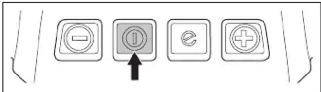
- Press the ON/OFF button on the control panel. All LED lamps and symbols disappear from the display.
- Remove the blade screw, spring washer, and blade.
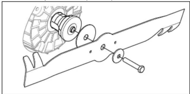
- Check if the blade support and blade screw are damaged.
a) If you replace the blade or blade support, also replace the blade screw, spring washer, and friction washer.
- Inspect the motor shaft to make sure it is not bent.
- When installing a new blade, make sure the bent ends are facing toward the cover of the mowing mechanism.
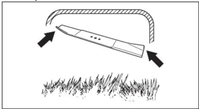
- Place the friction washer and blade against the blade support.
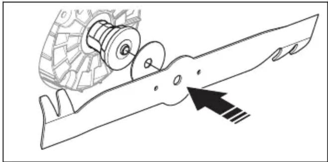
- Ensure the blade is aligned with the center of the motor shaft.
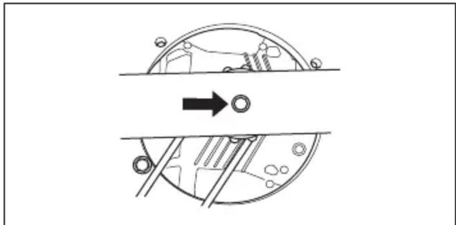
- Place the spring washer and tighten the screw to a torque of 65-75 Nm.
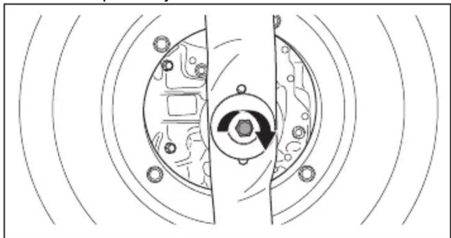
- Pull the blade by hand to check that it rotates freely.

WARNING: Use protective gloves. The blade is very sharp and cuts can easily occur.
- Start the product to test the blade. If the blade is not correctly installed, the product will vibrate or the mowing result will not be satisfactory.
Cleaning the product
- Clean plastic parts with a clean, dry cloth.
- Do not clean the product with water. Water can penetrate the battery or motor and cause a short circuit or damage to the product.
- Remove leaves, grass, and dirt with a brush.
- Remove the protective cover and use a brush to clean the inside of the protective cover from grass.
- Fold the handle forward.
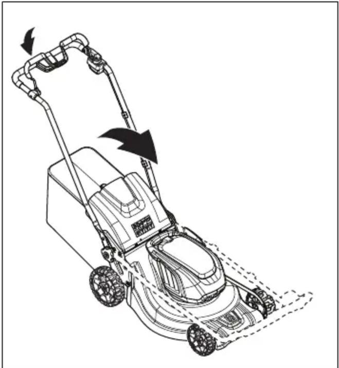
- Remove the grass catcher.
Transport
- Requirements for the transport of dangerous goods apply to the contained lithium-ion batteries.
- For commercial transport, special requirements must be observed as stated on the packaging and labels.
- Make sure to comply with dangerous goods transport regulations when preparing the product for transport. Local regulations may apply.
- Always remove the battery before transport.
- Place tape on the battery connectors and ensure that the battery cannot move during transport.
- Secure the product during transport.
Storage
- Always remove the battery before storage.
- To prevent accidents, make sure the battery is not connected to the product during storage.
- Keep the battery charger indoors and in a dry area.
- Keep the battery and battery charger in a dry area free from moisture or frost.
- Disconnect the battery from the battery charger during storage.
- Do not store the battery in places where static discharge may occur. Do not store the battery in a metal box.
- Store the battery in a place where the temperature is between 5 °C and 25 °C and away from direct sunlight.
- Store the battery charger in a place where the temperature is between 5 °C and 45 °C and out of direct sunlight.
- Make sure the battery is charged to 30% - 50% before storing for an extended period.
- Store the product, battery, and battery charger in a locked place out of the reach of children and unauthorized persons.
- Clean the product and perform complete servicing before storing the product for an extended period.
Disposal
Symbols on the product or its packaging indicate that this product cannot be handled as household waste. It must be taken to an appropriate recycling facility for the recovery of electrical and electronic equipment.
- Open the battery cover.
- Remove the battery from compartment 1.
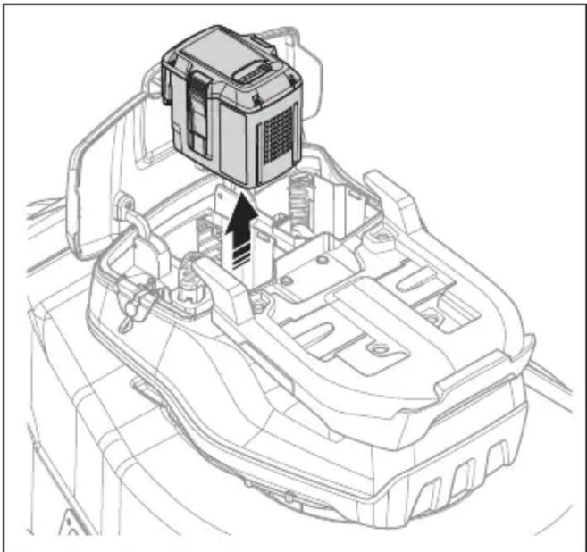
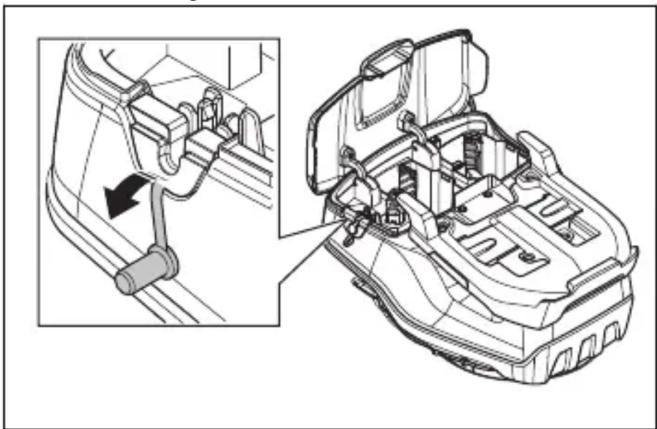
- Remove the seal.
- Insert the battery pack into the battery adapter.
- Connect the battery pack to the battery charger.
Mount the grass collector (LC 551iV)


- Fold the handle forward.


Technical data
Technical data


Danger - keep hands and feet away.
Product liability
Check the start interlock
Check the start interlock to ensure it prevents the motor from running.
- Remove the sealing rod.
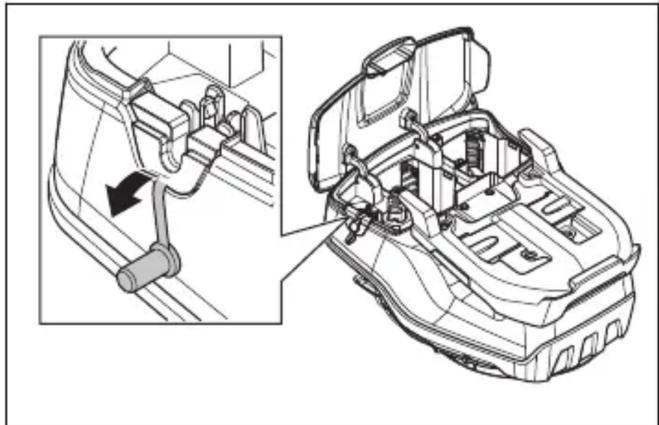
- Remove the multi-battery in reverse order.

Assemble the grass catcher bag (LC 551iV)
Operation
Introduction

- Drill 2 holes at the marks in the sensor slot.
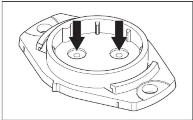
- Align the sensor slot with the housing slot.
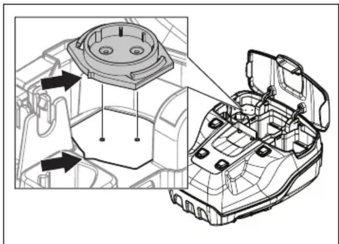


- Push the motor brake handle toward the handlebar.
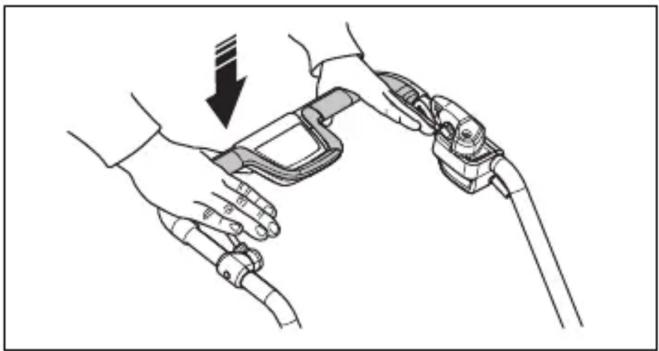
- Remove the blade bolt, spring washer, and blade.
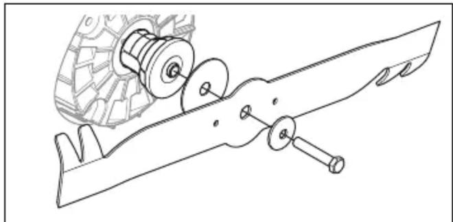
- Check the blade holder and blade bolts for damage.
- Place the friction washer and blade firmly against the blade holder.
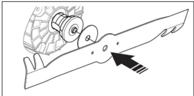
- Ensure the blade is centered with the motor shaft.
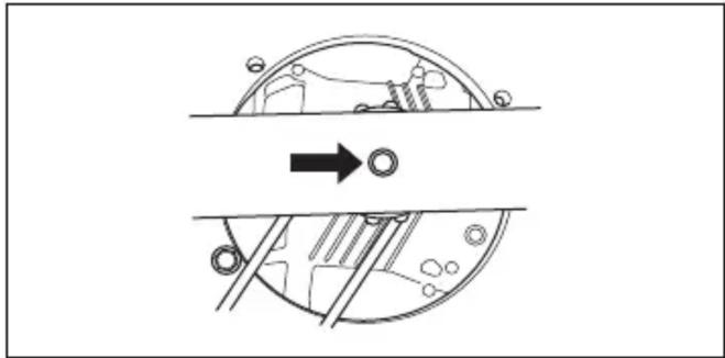
- Use a wooden block to wedge the blade.
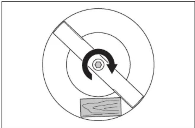
- Rotate the blade by hand to ensure it turns freely.

- Fold the handle forward.
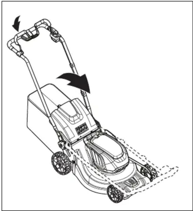
- Remove the grass catcher bag.
Transport
Technical data Technical data
Original instructions
Original instructions
Original instructions
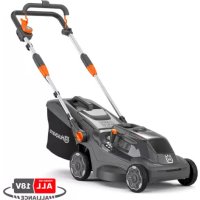
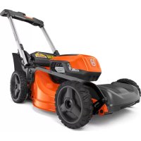
- LB 548I, LC 551IV, LB 553IV
- INTRODUCTION
- PRODUCT DESCRIPTION
- INTENDED USE
- SYMBOLS ON THE PRODUCT
- PRODUCT LIABILITY
- SAFETY
- SAFETY DEFINITIONS
- GENERAL SAFETY INSTRUCTIONS
- WORK AREA SAFETY
- WORK SAFETY
- SAFETY DEVICES ON THE PRODUCT
- TO DO A CHECK OF THE CUTTING COVER
- SAFETY KEY
- MOTOR BRAKE HANDLE
- TO EXAMINE THE START INHIBITOR
- BATTERY SAFETY
- BATTERY CHARGER SAFETY
- SAFETY INSTRUCTIONS FOR MAINTENANCE
- ASSEMBLY
- TO INSTALL AND REMOVE THE MULTI BATTERY (ACCESSORY)
- TO ADJUST THE HANDLE (LC 551IV)
- TO ASSEMBLE THE HANDLE (LB 548I, LB 553IV)
- TO ASSEMBLE THE GRASS CATCHER (LC 551IV)
- TO ASSEMBLE THE MULCH PLUG (LC 551IV ACCESSORY)
- OPERATION
- HUSQVARNA CONNECT
- TO START TO USE HUSQVARNA CONNECT
- HUSQVARNA FLEET SERVICES™
- TO PREPARE THE SENSOR (ACCESSORY)
- TO DO A PAIRING OPERATION BETWEEN THE APP AND THE PRODUCT
- TO INSTALL THE SENSOR
- TO SET THE PRODUCT IN OPERATION POSITION (LC 551IV)
- TO SET THE CUTTING HEIGHT (LB 548I, LC 551IV)
- TO SET THE CUTTING HEIGHT (LB 553IV)
- BATTERY
- BATTERY STATUS
- TO CHARGE THE BATTERY
- BATTERY CHARGING STATUS
- TO CHARGE THE MULTI BATTERY
- TO START THE PRODUCT
- TO USE THE WHEEL DRIVE (LC 551IV)
- TO USE THE WHEEL DRIVE (LB 553IV)
- TO MOVE THE PRODUCT WITH THE CUTTING EQUIPMENT DISENGAGED (LB 553IV)
- TO USE THE SAVE FUNCTION
- POWERBOOST FUNCTION
- MOTOR STALLING
- TO STOP THE PRODUCT
- TO GET A GOOD RESULT
- TO CUT GRASS WITHOUT A GRASS CATCHER OR MULCH PLUG ATTACHED (LC 551IV)
- MAINTENANCE
- MAINTENANCE SCHEDULE
- TO DO A GENERAL INSPECTION
- TO REPLACE THE BLADE
- TO CLEAN THE PRODUCT
- TO CLEAN THE BATTERY AND THE BATTERY CHARGER
- TO EXAMINE THE CUTTING EQUIPMENT
- TROUBLESHOOTING
- BATTERY CHARGER
- CONTROL PANEL
- TRANSPORTATION, STORAGE AND DISPOSAL
- TO SET THE PRODUCT IN TRANSPORT POSITION (LC 551IV)
- TRANSPORTATION
- STORAGE
- DISPOSAL
- DECLARATION OF CONFORMITY
- EU DECLARATION OF CONFORMITY
- UK DECLARATION OF CONFORMITY
- CONTENTS
- TECHNICAL DATA
- TO MOVE THE PRODUCT WITH THE CUTTING EQUIPMENT DISABLED (LB 553IV)
- ASSEMBLY OF THE MULCHING PLUG (LC 551IV ACCESSORY)
- TOWING ON WHEELS (LC 551IV)
- NOTE: DO NOT PLACE
- PRODUCT RELIABILITY
- START INTERLOCK CHECK
- MOUNTING THE GRASS COLLECTOR (LC 551IV)
- ASSEMBLING THE MULCHING PLUG (LC 551IV OPTIONAL EQUIPMENT)
- PAIRING THE APP WITH THE PRODUCT
- BATTERY CHARGER STATUS
- CHARGING THE MULTI-BATTERY
- USING THE WHEEL DRIVE (LC 551IV)
- MOVING THE PRODUCT WITH THE CUTTING EQUIPMENT SWITCHED OFF (LB 553IV)
- USING THE SAVE FUNCTION
- INSPECTION OF THE START INHIBITOR DEVICE
- TRANSPORT
- MAIN SPECIFICATIONS
- HOW TO MOVE WITH THE PRODUCT WHEN THE CUTTING EQUIPMENT IS DISCONNECTED (LB 553IV)
- INSTALL THE GRASS CATCHER (LC 551IV)
- INSTALL THE MULCHING PLUG (ACCESSORY LC 551IV)
- CHARGE THE BATTERY
- CHARGE THE MULTI-BATTERY
- HOW TO INSTALL THE FINE DISTRIBUTION PLUG (LC 551IV ACCESSORY)
- HOW TO SET THE PRODUCT IN WORKING POSITION (LC 551IV)
- HOW TO CHARGE THE MULTI-BATTERY
- CHECK THE START INHIBITOR
- MOUNT THE GRASS COLLECTOR (LC 551IV)
- CHECK THE START-UP FUSE
- SETTING THE CUTTING HEIGHT (LB 553IV)
- FOR WHEEL DRIVE (LC 551IV)
- STARTING INHIBITOR CHECK
- ADJUSTING THE HANDLE (LC 551IV)
- FOLDING THE HANDLE (LB 548I, LB 553IV)
- FOLDING THE GRASS CATCHER (LC 551IV)
- INSTALLING THE MULCHING ATTACHMENT (LC 551IV EQUIPMENT)
- PERFORMING THE PAIRING PROCESS BETWEEN THE APP AND THE PRODUCT
- INSTALLING THE SENSOR
- ADJUSTING THE CUTTING HEIGHT (LB 548I, LC 551IV)
- USING THE WHEEL DRIVE (LB 553IV)
- MOVING THE PRODUCT WITH THE CUTTING EQUIPMENT DEACTIVATED (LB 553IV)
- CLEANING THE PRODUCT
- CHECK THE START INTERLOCK
- ASSEMBLE THE GRASS CATCHER BAG (LC 551IV)
Brand : HUSQVARNA
Model : LB 553iV
Category : Electric mower