
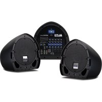
AEQ215 - Hi-fi system ALTO - Free user manual and instructions
Find the device manual for free AEQ215 ALTO in PDF.
| Product Type | Professional 2-channel graphic equalizer |
| Number of bands | 30 bands per channel (2/3 octave spacing) |
| Gain range | ±6 dB or ±15 dB (selectable) |
| Filters | High-pass 40 Hz (12 dB/octave), low-pass 16 kHz (12 dB/octave) |
| Input connectors | Balanced XLR, balanced 1/4" TRS, unbalanced RCA |
| Output connectors | Balanced XLR, balanced 1/4" TRS, unbalanced RCA |
| Power supply | Mains 230 V / 50 Hz (power adapter included) |
| Dimensions (W x H x D) | 48 x 4.4 x 15 cm (19" rack format, 1U) |
| Weight | 2.5 kg |
| Main functions | Graphic equalization, per-channel bypass, amplitude selector, ground lift switch, clipping indicators, high-pass and low-pass filters |
| Recommended use | Recording studio, live sound, fixed installation |
| Maintenance and cleaning | Unplug the device before cleaning. Use a dry, lint-free cloth. Avoid solvents and liquids. |
| Safety | Exposure to high sound levels can cause hearing loss. Use hearing protection if necessary. Read the safety instructions. |
| Spare parts and repairability | Contact Alto Professional after-sales service for any repairs. Internal calibrated fuse. |
| Included accessories | Power cable, user guide, safety instructions and warranty booklet |
| Warranty | Consult the included booklet or Alto Professional website |
Frequently Asked Questions - AEQ215 ALTO
User questions about AEQ215 ALTO
0 question about this device. Answer the ones you know or ask your own.
Ask a new question about this device
Download the instructions for your Hi-fi system in PDF format for free! Find your manual AEQ215 - ALTO and take your electronic device back in hand. On this page are published all the documents necessary for the use of your device. AEQ215 by ALTO.
USER MANUAL AEQ215 ALTO
AEQ215
USER GUIDE
ENGLISH (3 - 10)
GUÍA DEL USUARIO
ESPAÑOL (11 - 18)
GUIDE D'UTILISATION
FRANÇAIS (19 - 26)
GUIDA PER L'USO
ITALIANO (27 - 34)
BENUTZERHANDBUCH
DEUTSCH (35-42)
GEBRUIKERSHANDLEIDING
NEDERLANDS (43 - 50)
USER GUIDE (ENGLISH)
BOX CONTENTS
AEQ215
• Power Cable
- User Guide
• Safety & Warranty Information Booklet
- Make sure all items listed in the BOX CONTENTS section are included in the box.
- READ THE SAFETY & WARRANTY INFORMATION BOOKLET BEFORE USING THE PRODUCT.
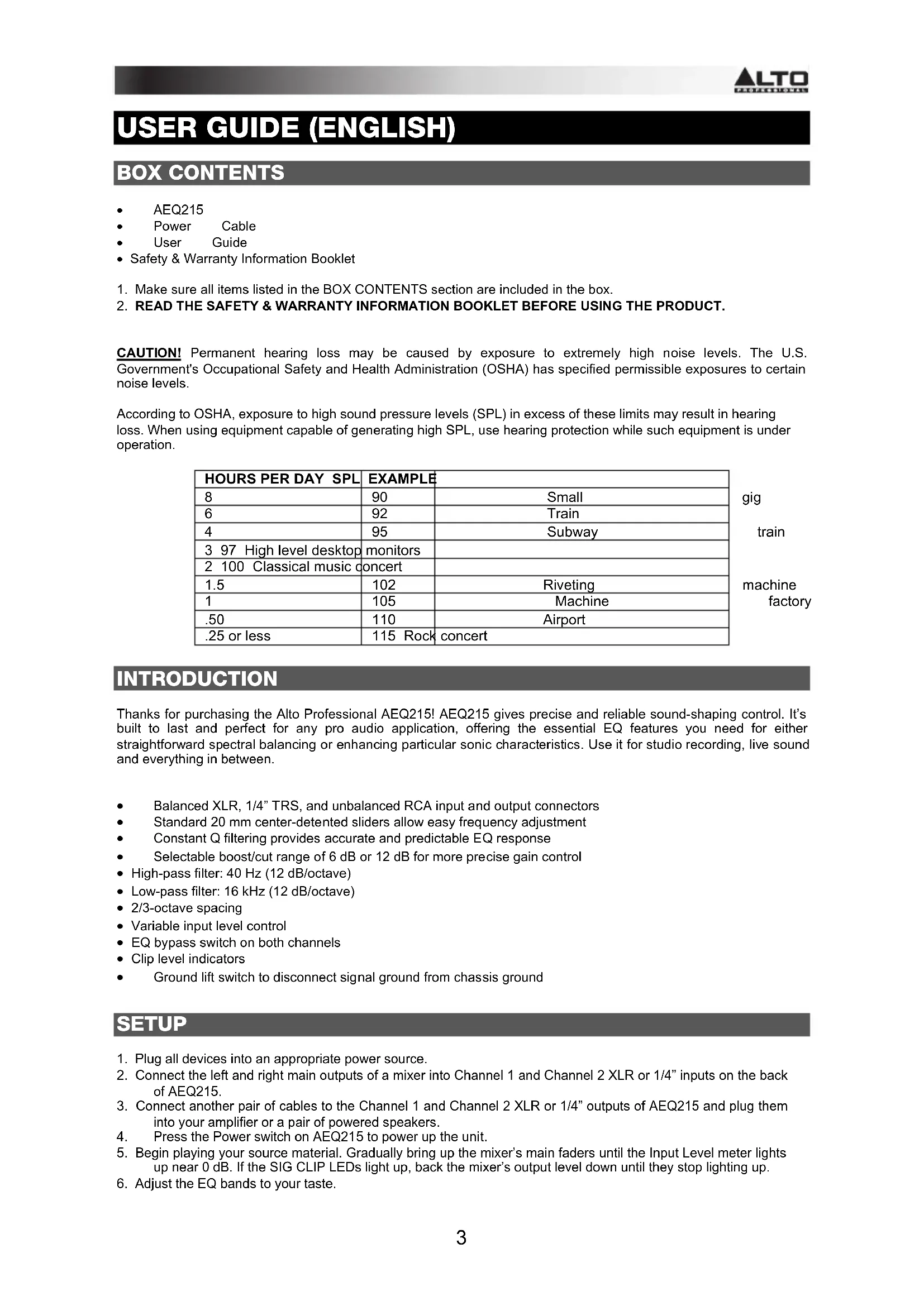
CAUTION! Permanent hearing loss may be caused by exposure to extremely high noise levels. The U.S. Government's Occupational Safety and Health Administration (OSHA) has specified permissible exposures to certain noise levels.
According to OSHA, exposure to high sound pressure levels (SPL) in excess of these limits may result in hearing loss. When using equipment capable of generating high SPL, use hearing protection while such equipment is under operation.
| HOURS PER DAY SPL | EXAMPLE | |
| 8 | 90 | Small |
| 6 | 92 | Train |
| 4 | 95 | Subway |
| 3 97 High level desktop | monitors | |
| 2 100 Classical music concert | ||
| 1.5 | 102 | Riveting |
| 1 | 105 | Machine |
| .50 | 110 | Airport |
| .25 or less | 115 Rock concert |
INTRODUCTION
Thanks for purchasing the Alto Professional AEQ215! AEQ215 gives precise and reliable sound-shaping control. It's built to last and perfect for any pro audio application, offering the essential EQ features you need for either straightforward spectral balancing or enhancing particular sonic characteristics. Use it for studio recording, live sound and everything in between.
• Balanced XLR, 1/4" TRS, and unbalanced RCA input and output connectors
• Standard 20 mm center-detented sliders allow easy frequency adjustment
• Constant Q filtering provides accurate and predictable EQ response
- Selectable boost/cut range of 6 dB or 12 dB for more precise gain control
• High-pass filter: 40 Hz (12 dB/octave)
- Low-pass filter: 16 kHz (12 dB/octave)
• 2/3-octave spacing
• Variable input level control
• EQ bypass switch on both channels
- Clip level indicators
• Ground lift switch to disconnect signal ground from chassis ground
SETUP
- Plug all devices into an appropriate power source.
- Connect the left and right main outputs of a mixer into Channel 1 and Channel 2 XLR or 1/4" inputs on the back of AEQ215.
- Connect another pair of cables to the Channel 1 and Channel 2 XLR or 1/4" outputs of AEQ215 and plug them into your amplifier or a pair of powered speakers.
- Press the Power switch on AEQ215 to power up the unit.
- Begin playing your source material. Gradually bring up the mixer's main faders until the Input Level meter lights up near 0 dB. If the SIG CLIP LEDs light up, back the mixer's output level down until they stop lighting up.
- Adjust the EQ bands to your taste.
FRONT PANEL
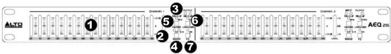
- EQ Bands – Use these sliders to boost or cut the level of each audio frequency band. When all the sliders are in the center position, the equalizer outputs a flat frequency response.
- Input Level Meter – Displays the level of the incoming signal. The "0 dB" position is unity gain (no boost or attenuation). If the clip LED lights continuously, turn down this control.
- SIG CLIP – Flashes red when the input or output signal gets within 5 dB of clipping. If this occurs, turn down the input or output signal to avoid distortion.
- Range – Selects which of the two boost/cut ranges the EQ band sliders will use, either ±6 dB or ±15 dB. WARNING: Adjusting this switch generates a loud transient. Before changing the setting of the switch, reduce the audio level of your power amplifier.
- Hi Pass - Reduces the low frequencies from the signal.
- Low Pass – Reduces the high frequencies from the signal.
- EQ On – Select to bypass the EQ and hear the unprocessed signal.
REAR PANEL
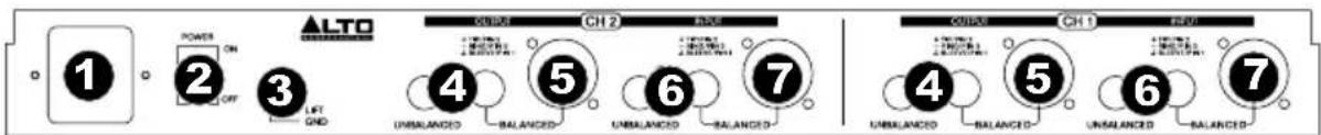
- Power Connector – Connect the included power cable here.
- Power Switch – Use this switch to power AEQ215 on/off.
- Ground Lift - Disconnects the signal ground from the chassis ground. If the equalizer is causing any hum or buzz in your system due to a ground loop, move this switch to the "lift" position.
- RCA Outputs – Connect these outputs to a mixer's Aux Return or powered speakers.
- 1/4" and XLR Outputs – Connect these outputs to a mixer's Aux Return or powered speakers.
- RCA Inputs – Connect these inputs to a mixer's Main output or Aux Send.
- 1/4" and XLR Inputs – Connect these inputs to a mixer's Main output or Aux Send.
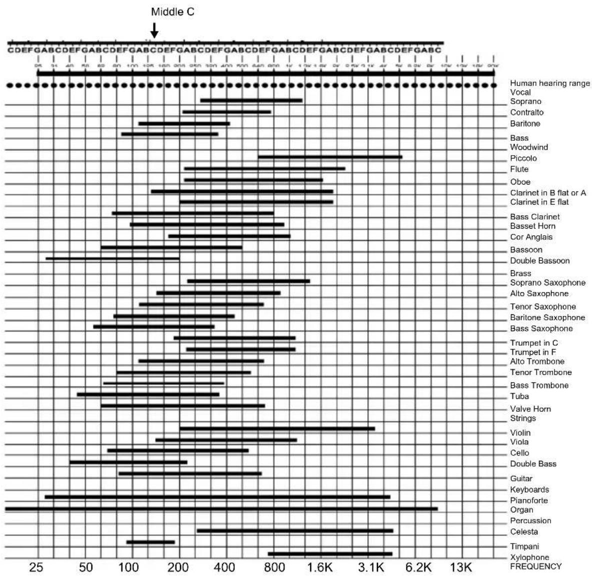
THE FREQUENCY SPECTRUM
Graphic EQs are used in recording studios, live performances, and radio and TV broadcasts. They are commonly used to fine-tune the sound of an individual instrument or smooth an entire mix. When considering how different instruments and voices fit into the audio spectrum, it is helpful to refer to their known frequency ranges. Understanding an instrument's frequency range will be extremely helpful when balancing spectral inconsistencies within the mix. Refer to the table below to get an idea of an instrument's frequency range and acoustic significance.
Typical Frequency of Each Instrument and Voice
bar
| Instrument | Frequency | | --- | --- | | Vocal | 1300 | | Soprano | 800 | | Contralto | 700 | | Baritone | 400 | | Bass | 300 | | Woodwind | 250 | | Piccolo | 600 | | Flute | 500 | | Oboe | 450 | | Clarinet in B flat or A | 400 | | Clarinet in E flat | 350 | | Bass Clarinet | 300 | | Basset Horn | 250 | | Cor Anglais | 200 | | Bassoon | 150 | | Double Bassoon | 100 | | Brass | 50 | | Soprano Saxophone | 45 | | Alto Saxophone | 40 | | Tenor Saxophone | 35 | | Baritone Saxophone | 30 | | Bass Saxophone | 25 | | Trumpet in C | 20 | | Trumpet in F | 15 | | Alto Trombone | 10 | | Tenor Trombone | 5 | | Bass Trombone | 4 | | Tuba | 3 | | Valve Horn | 2 | | Strings | 1 | | Violin | 0 | | Viola | 0 | | Cello | 0 | | Double Bass | 0 | | Guitar | 0 | | Keyboards | 0 | | Pianoforte | 0 | | Organ | 6.2K | | Percussion | 4.5K | | Celesta | 3.5K | | Timpani | 2.5K | | Xylophone | 2.0K | | FREQUENCY | 1.5K |WHAT IS EQUALIZATION?
An equalizer boosts or cuts a frequency range. The Alto Professional AEQ215 is a graphic equalizer. Graphic equalizers have fixed frequency bands that can be boosted or cut. The term "graphic" is appropriate because the combined settings of the bands often resemble a curve or "graph."
The most basic level of control on a graphic equalizer is the gain setting for a given band. Each of the bands represent a predetermined frequency range; its gain setting controls the amount of boost or cut for that frequency range. A setting of 0 dB means that the signal will not be affected in the area of those audio frequencies.
Depending on the program material, boosting or cutting just one frequency can have a significant impact on the sound. When all of the frequency bands are taken together, the impact can be huge.
Equalization can be used for:
- Adjusting the character of an instrument, voice, mix, or effect
- Cutting or boosting frequencies to make a source easier to mix with other tracks
• Compensating for a less-than-ideal recording
• Compensating for less-than-ideal room acoustics - Creating a filter effect
- Eliminating buzz, noise, or hum
APPLICATIONS
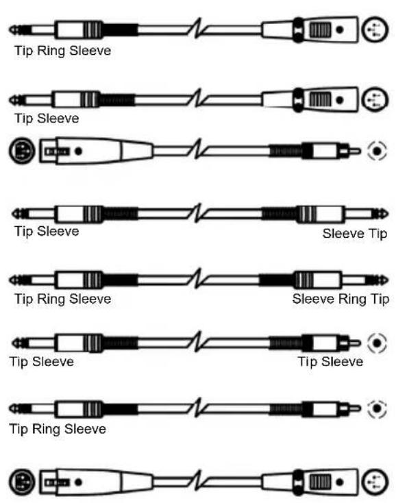
AEQ215 uses balanced XLR, balanced 1/4" TRS and unbalanced RCA connectors. They can be interfaced in several ways to support a variety of applications. Three common configurations are:
• Main Mix Insert: EQ the entire mix.
Aux (Monitor) Out "In-Line" EQ the auxiliary outputs that feed stage monitors.
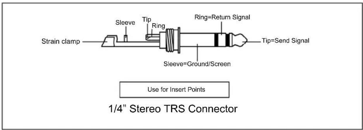
• Channel Insert: EQ a single instrument (requires a TRS Insert cable)
For best performance, and to avoid unwanted noise or signal loss, use only high quality shielded audio cables. For further details, please refer to the INSTALLATION AND CONNECTION section.
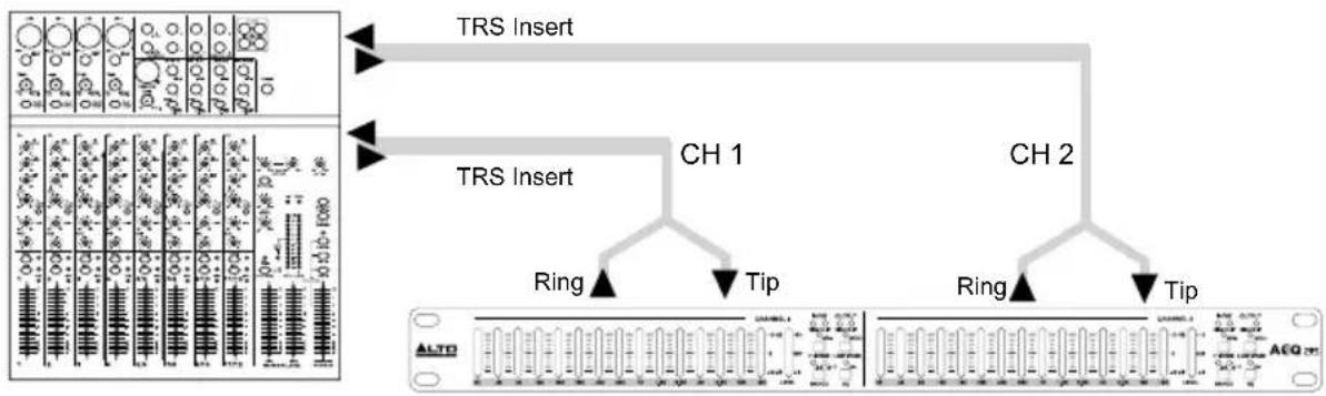
Connecting the AEQ215 to the Left and Right Main Mix Inserts
2 TRS insert cables (1 TRS 1/4" Male to 2 Mono 1/4" Male) will be required for both left and right mixer channels.
- Connect the TRS end of the Insert cable to the mixer's left Main Insert.
- Connect the Tip end of the Insert cable to the balanced 1/4" Channel 1 input on AEQ215.
- Connect the Ring end of the Insert cable to the balanced 1/4" Channel 1 output on AEQ215.
- For the connection between the mixer's right output and Channel 2 on AEQ215, follow the same pattern as seen in Steps 1-3.
flowchart
graph TD
    A["TRS Insert"] --> B["CH 1"]
    C["TRS Insert"] --> D["CH 2"]
    E["Ring"] --> F["Tip"]
    G["Ring"] --> H["Tip"]
    I["AEG Channel"] --> J["Pin 1"]
    K["AEG Channel"] --> L["Pin 2"]
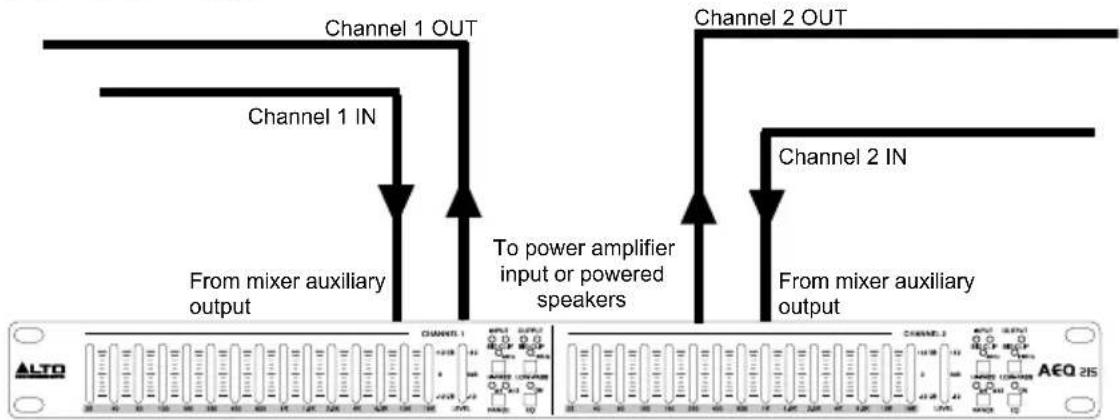
Connecting the AEQ215 from Mixer auxiliary outputs ("In-Line")
Adding EQ to stage monitors is helpful in controlling feedback and shaping the perfect monitor mix. In this configuration, EQ will be applied to the monitor path only.
Note: We recommended using pre-fader auxiliary sends for controlling stage monitor levels.
- Connect Mixer auxiliary Output 1 to the XLR Balanced Input or 1/4" TRS on AEQ215 Channel 1.
- Connect AEQ215 Channel 1 output to amplifier input or powered loudspeaker input. The EQ is now "in-line" between the mixer Auxiliary output and loudspeaker amplifier.
- For the connection between the mixer's auxiliary output 2 and Channel 2 input on AEQ215 follow the same pattern as seen in steps 1-2.
flowchart
graph TD
    A["From mixer auxiliary output"] --> B["Channel 1 IN"]
    B --> C["Channel 1 OUT"]
    C --> D["To power amplifier input or powered speakers"]
    D --> E["Channel 2 IN"]
    E --> F["Channel 2 OUT"]
    F --> G["From mixer auxiliary output"]
Inserting the AEQ215 on a Mixer Channel Insert
Stereo Insert cable (1 TRS 1/4" Male to 2 Mono 1/4" Male) will be required for this configuration. AEQ215 channel 1 is listed for example only. Both channels can be used in this configuration. Use only one AEQ215 channel per mixer channel insert.
- Connect the TRS end of the Insert cable to the mixer's Channel Insert.
- Connect the Tip end of the Insert cable to the balanced 1/4" Channel 1 input of AEQ215.
- Connect the Ring end of the Insert cable to the balanced 1/4" Channel 1 output of AEQ215.

flowchart
graph TD
    A["Channel Insert"] --> B["CH 1 OUT"]
    A --> C["CH 1 IN"]
INSTALLATION AND CONNECTION
Read this section carefully. Not paying enough attention to the input signal's level, routing, or assignment of can result in unwanted distortion, a corrupted signal or no sound at all.
Power Connection
Use the same fuse as marked on the fuse holder near the power connector. Connect AEQ215 to a standard power outlet using the included power cable.
Audio Connection
AEQ215 is equipped with balanced XLR connectors. It can be connected to other units in a variety of ways to support a vast range of applications without experiencing signal loss. Use only high-quality shielded audio cables.
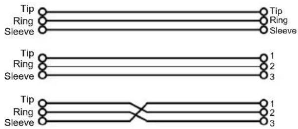
Wiring Configuration
AEQ215 has both balanced and unbalanced connections, ensuring compatibility with other common audio processors and mixers.
Please see following drawings for details:
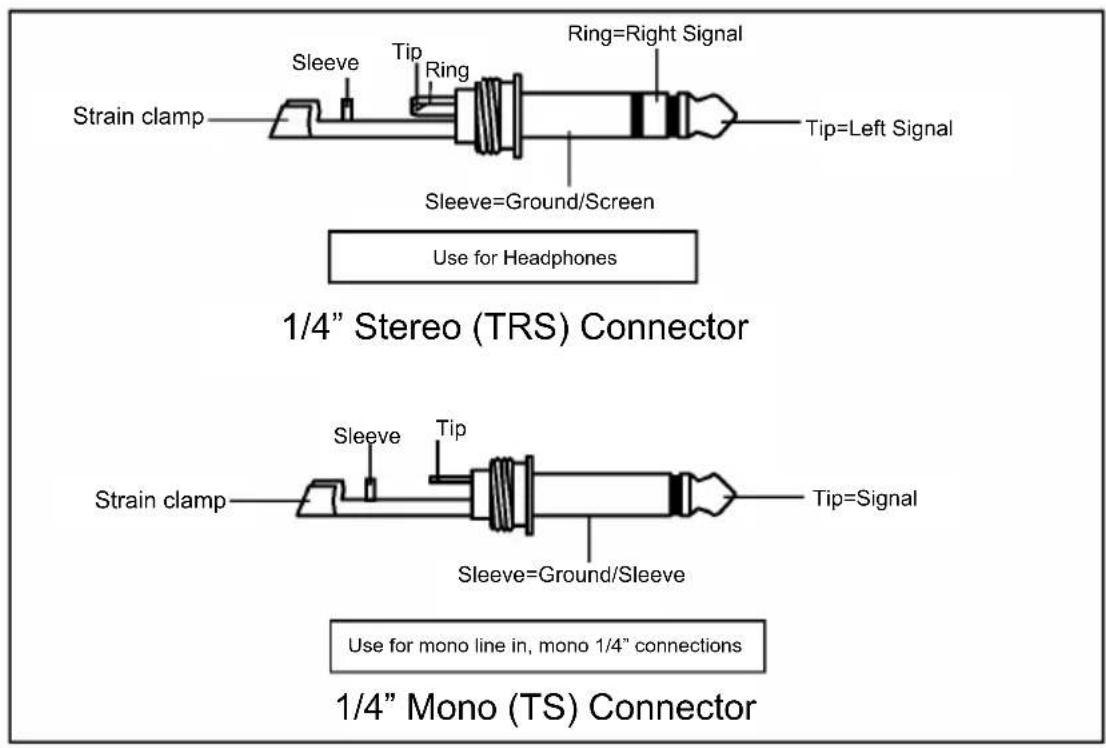

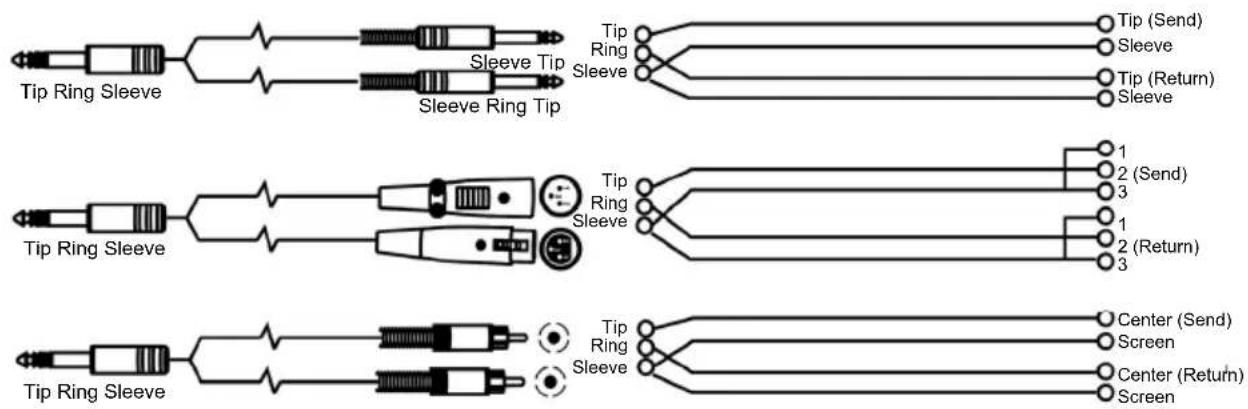
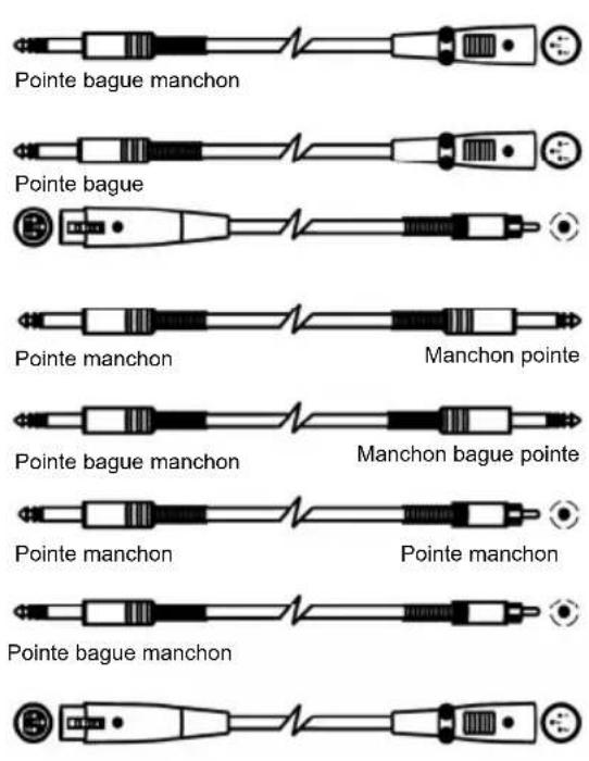
Line Connection
For these applications, AEQ215 has 1/4" TRS connectors and XLR connectors to easily interface with most professional audio devices. Follow the configuration examples below for your particular connection.
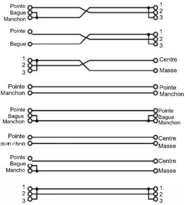
- Balanced

flowchart
graph TD
    A["Top Left"] --> B["Tip"]
    A --> C["Ring"]
    A --> D["Sleeve"]
    E["Top Right"] --> F["Tip"]
    E --> G["Ring"]
    E --> H["Sleeve"]
    I["Bottom Left"] --> J["Tip"]
    I --> K["Ring"]
    I --> L["Sleeve"]
    M["Bottom Right"] --> N["Tip"]
    M --> O["Ring"]
    M --> P["Sleeve"]
- Unbalanced

flowchart
graph TD
    A["Tip"] --> B["Ring"]
    B --> C["Sleeve"]
    C --> D["1"]
    C --> E["2"]
    C --> F["3"]
    G["Tip"] --> H["Ring"]
    H --> I["Sleeve"]
    I --> J["1"]
    I --> K["2"]
    I --> L["3"]
    M["1"] --> N["Center"]
    O["2"] --> P["Screen"]
    Q["3"] --> R["Center"]
    S["Tip"] --> T["Sleeve"]
    U["Tip"] --> V["Sleeve"]
    W["Tip"] --> X["Sleeve"]
    Y["Tip"] --> Z["Sleeve"]
    AA["Tip"] --> AB["Sleeve"]
    AC["Tip"] --> AD["Sleeve"]
    AE["Tip"] --> AF["Sleeve"]
    AG["Tip"] --> AH["Sleeve"]
    AI["1"] --> AJ["Center"]
    AK["2"] --> AL["Screen"]
    AM["3"] --> AN["Center"]
EQ TIPS
Here are some general EQ tips to try out:
Rock Kick Drum
A rock kick drum is usually EQ'd quite a bit to make it sound the way it does on the radio. Usually an engineer will cut some of the low-midrange, while boosting the high end and some of the lows. Here is a setting to try on a close-mic'd kick drum:
- Select all frequencies below 100 Hz and boost 3 dB
• Cut 400 Hz by 8 dB - Boost all frequencies above 4 kHz by 4 dB
Note: Depending on the incoming audio, you may need to reduce the gain on some frequency bands to prevent clipping.
Vocal Air
A popular effect on vocals is to boost the high frequencies to add "air" to the vocals. This effect is achieved by boosting the high frequencies:
- Boost 16 kHz by 6dB
Eliminating Feedback
During a live performance, you may experience feedback if a microphone is placed too close to a monitor. However, feedback often occurs at one frequency before it happens at others. You can "ring out" the monitor by using EQ to cut the frequency that is feeding back. Try this when the band and audience are not present:
- Insert the EQ between the mixer's monitor output and the monitor amplifier.
- Slowly raise the monitor level to the point of feedback. As soon as you hear feedback, turn the monitor level down, but not off.
- Select an EQ band that is near where you think the feedback is occurring. For example, if you're getting high-frequency feedback, try 6.3 kHz.
- Slowly raise the 6.3 kHz band level while listening for feedback. If you hear feedback, cut that frequency. If you don't hear feedback, return that band to "0" and repeat this procedure with another frequency band.
- If you don't hear feedback at any frequency using this method, try boosting the monitor level a little more, and repeat the process.
INSTALLING AEQ215 IN A RACK
AEQ215 can be installed in a standard 19" audio equipment rack (occupying one rack space). When you install it, allow adequate ventilation behind AEQ215.
GUÍA DEL USUARIO (ESPAÑOL)
CONTENIDO DE LA CAJA
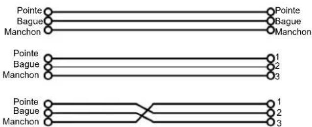
flowchart
graph TD
    A["Pointe"] --> B["Pointe"]
    C["Bague"] --> D["Bague"]
    E["Manchon"] --> F["Manchon"]
    G["Pointe"] --> H["1"]
    I["Bague"] --> J["2"]
    K["Manchon"] --> L["3"]
    M["Pointe"] --> N["1"]
    O["Bague"] --> P["2"]
    Q["Manchon"] --> R["3"]
- Asymétrique
CONSEILS POUR L'ÉGALISATION
flowchart
graph TD
    A["Switch Panel"] -->|Channel Insert| B["Switch Block"]
    B --> C["Channel 1 OUT"]
    B --> D["Channel 1 IN"]
Connectors: XLR, 1/4" TRS
Impedance:
• > 20 KΩ (balanced)
• > 15 KΩ (unbalanced)
Max. Input Level: +18 dBV
OUTPUT
Connectors: XLR, 1/4" TRS
Impedance: > 600 Ω
Max. Output Level: +16 dBV
CONTROLS
Sliders Type: 20 mm, with center detent
Control Range: +0/-6 dB or 12 dB selectable
High Pass Filter: 40 Hz (12 dB/oct)
Low Pass Filter: 16 kHz (12 dB/oct)
PERFORMANCE
Frequency Response: < 20 Hz - < 50 kHz, +0/-3 dB (all sliders at center)
Signal-to Noise Ratio: 117 dB
THD%: 0.02% (at 1 kHz, all sliders at center)
POWER
Power Consumption: 15 W (max)
Power Supply: AC 100-120V\~50/60 Hz; Fuse: T160 mAL AC 250V
220-240V\~ 50/60 Hz; Fuse: T100 mAL, AC 250V
DIMENSIONS
(LxWxH): 7.4" x 19" x 1.7"; 187 mm x 483 mm x 44 mm
WEIGHT
6.2 lb.; 2.8 kg
www.altoprofessional.com

- AEQ215
- USER GUIDE (ENGLISH)
- BOX CONTENTS
- INTRODUCTION
- SETUP
- FRONT PANEL
- REAR PANEL
- THE FREQUENCY SPECTRUM
- WHAT IS EQUALIZATION?
- Equalization can be used for:
- APPLICATIONS
- Connecting the AEQ215 to the Left and Right Main Mix Inserts
- Connecting the AEQ215 from Mixer auxiliary outputs ("In-Line")
- Inserting the AEQ215 on a Mixer Channel Insert
- INSTALLATION AND CONNECTION
- Power Connection
- Audio Connection
- Wiring Configuration
- Line Connection
- EQ TIPS
- Rock Kick Drum
- Vocal Air
- Eliminating Feedback
- INSTALLING AEQ215 IN A RACK
- GUÍA DEL USUARIO (ESPAÑOL)
- CONTENIDO DE LA CAJA
- - Asymétrique
- CONSEILS POUR L'ÉGALISATION
- OUTPUT
- CONTROLS
- PERFORMANCE
- POWER
- DIMENSIONS
- WEIGHT
Brand : ALTO
Model : AEQ215
Category : Hi-fi system