
Stealth Pro - Hi-fi system ALTO - Free user manual and instructions
Find the device manual for free Stealth Pro ALTO in PDF.
| Brand | ALTO |
| Model | Stealth Pro |
| Product Type | Wireless audio transmission system (transmitter and receiver) |
| Main Functions | Wireless audio transmission, mono/stereo modes, automatic frequency scanning, automatic synchronization, delay adjustment, adjustable squelch |
| Transmitter Connectivity | 2 combo inputs (XLR / 6.35 mm jack) balanced/unbalanced |
| Receiver Connectivity | 1 balanced mini XLR audio output |
| Power Supply | 12V 1.0 A AC adapter (included) |
| Antennas | Removable BNC (6 included) |
| Mounting | Receiver: M10 mounting point for speaker; transmitter: rack mountable (kit included) |
| Range | Up to 60 meters (200 feet) in open field |
| Available Channels | Variable depending on region |
| Transmission Modes | Selectable mono or stereo |
| Display | LCD screen on transmitter and receiver (frequency, channel, audio level, etc.) |
| Safety | Observe recommended sound levels; do not expose to moisture |
| Maintenance | Clean with a soft, dry cloth |
| Box Contents | Transmitter (1), receivers (2), AC adapters (3), mini XLR to XLR cables (2), antennas (6), mounting brackets, bolts, user guide |
| Warranty | Refer to the included safety and warranty guide |
Frequently Asked Questions - Stealth Pro ALTO
User questions about Stealth Pro ALTO
0 question about this device. Answer the ones you know or ask your own.
Ask a new question about this device
Download the instructions for your Hi-fi system in PDF format for free! Find your manual Stealth Pro - ALTO and take your electronic device back in hand. On this page are published all the documents necessary for the use of your device. Stealth Pro by ALTO.
USER MANUAL Stealth Pro ALTO
User Guide (English)
Introduction
Box Contents
| Stealth Pro Transmitter (x1) | Short Rack Ear (x2) |
| Stealth Pro Receiver (x2) | Long Rack Ear (x1) |
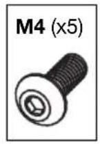
| Power Adapters (x3) | M4 Rack Ear Coupling Bolts (x5) |
| Mini-XLR to XLR Cables (x2) | Center Coupling Bracket (x1) |
| Removable Antennas (x6) | User Guide |
| M10 Rigging Bolts (x2) | Safety & Warranty Manual |
Support
For the latest information about this product (system requirements, compatibility information, etc.) and product registration, visit altoprofessional.com.
For additional product support, visit altoprofessional.com/support.
Important Safety Precautions
Please note: Alto Professional and inMusic are not responsible for the use of its products or the misuse of this information for any purpose. Alto Professional and inMusic are not responsible for the misuse of its products caused by avoiding compliance with inspection and maintenance procedures. Please also refer to the included safety and warranty manual for more information.
Sound Level
Permanent hearing loss may be caused by exposure to extremely high noise levels. The U.S. Occupational Safety and Health Administration (OSHA) has specified permissible exposures to certain noise levels. According to OSHA, exposure to high sound pressure levels (SPL) in excess of these limits may result in hearing loss. When using equipment capable of generating high SPL, use hearing protection while such equipment is under operation.
| Hours per day | SPL (dB) | Example | |
| 8 | 90 | Small | gig |
| 6 | 92 | Train | train |
| 4 | 95 | Subway | |
| 3 | 97 | High level desktop monitors | music |
| 2 | 100 | Classical | |
| 1.5 | 102 | Riveting | machine |
| 1 | 105 | Machine | factory |
| 0.50 | 110 | Airport | |
| 0.25 or less | 115 | Rock concert |
Quick Start
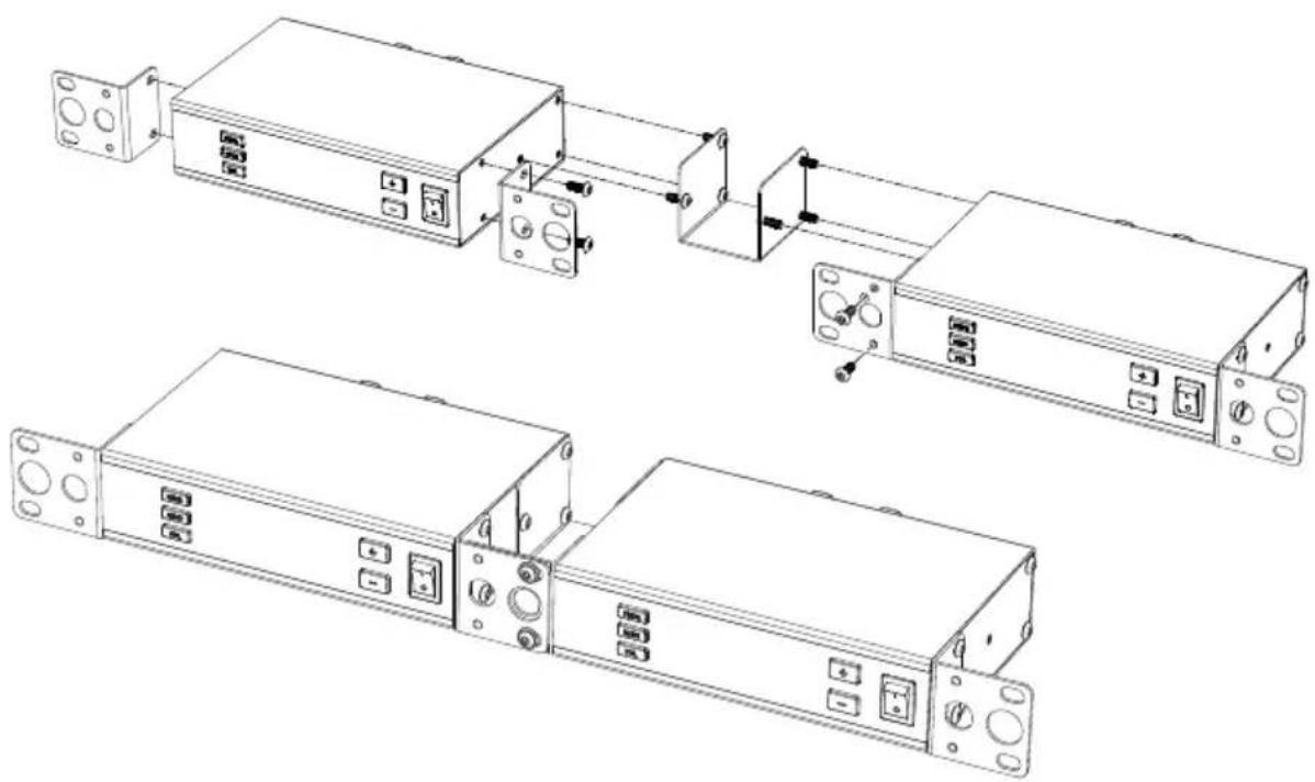
Assembly
Note: If you require assistance, contact Alto Professional customer service at altoprofessional.com/support.
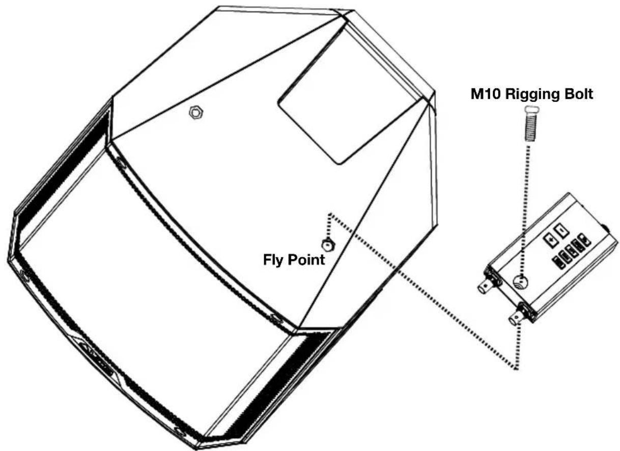
Mounting the Receiver to the Loudspeaker
Use the supplied M10 rigging bolts to connect the Stealth Pro Wireless receiver to the powered speaker's fly point.
Rack-Mounting One Transmitter
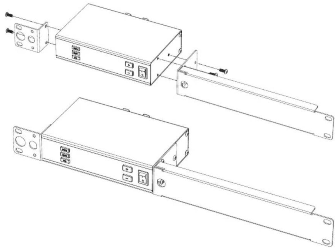
Rack-Mounting Two Transmitters

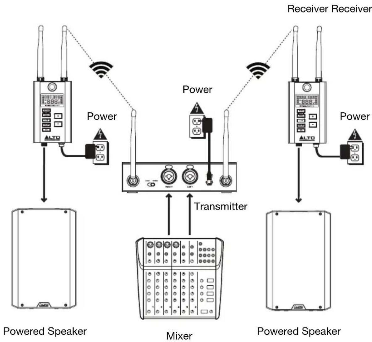
Connection Diagrams
Items not listed under Introduction > Box Contents are sold separately.
Example 1 - Mono Operation
To send mono signals through the Stealth Pro transmitter to a single receiver:
- Connect your mixer's main output to an input on the Stealth Pro transmitter, and connect the receiver's output to your loudspeaker's input. Keep all mixer volume and transmitter volume controls at their minimum settings.
Note: When the transmitter is set to Mono, either input can be transmitted on both channels. This allows you to adjust the signal levels being sent to separate zones, for example. - Power on the Stealth Pro transmitter and receiver. Set their channels to matching numbers. See the instructions for using the Auto Sync function in Operation for more information.
- Adjust the transmitter and receiver antennas to a vertical position for best results in transmitting the wireless signal. If the wireless signal quality is poor, change the position of the antennas.
- Set the transmitter to Mono and adjust the Volume control to get a strong signal without clipping.
- Turn on your loudspeaker, adjust the output level on your mixer, and adjust the Volume control on the transmitter to hear the audio signal. If you hear noise in the signal, change to a different channel until a clean signal comes through. See the instructions for changing the RF frequency in Operation for more information.

Example 2 - Stereo Operation
To send stereo signals through the Stealth Pro transmitter to two receivers:
- Connect your mixer's main outputs to the corresponding input channels on the Stealth Pro transmitter, and connect the receivers' outputs to your loudspeakers' inputs. Keep all mixer volume and transmitter volume controls at their minimum settings.
- Power on the Stealth Pro transmitter and receivers. Set their channels to matching numbers. See the instructions for using the Auto Sync function in Operation for more information.
- Adjust the transmitter and receiver antennas to a vertical position for best results in transmitting the wireless signal. If the wireless signal quality is poor, change the position of the antennas.
- Set the transmitter to Stereo and adjust the Volume control to get a strong signal without clipping.
- Turn on your loudspeakers, adjust the output level on your mixer, and adjust the Volume control on the transmitter to hear the audio signal. If you hear noise in the signal, change to a different channel until a clean signal comes through. See the instructions for changing the RF frequency in Operation for more information.
Operation
To set up and use your Stealth Pro, follow the steps in this chapter in order. If you are setting up a system using multiple receivers, set up each receiver one at a time, and keep each receiver powered on as you set up additional units.
Setting Up the Receiver
Frequency Selection
- Use the included mini-XLR to XLR cable to connect the receiver's Audio Output to your loudspeaker.
- Use the included power adapter to connect the receiver's power connector to your power source. The receiver will power on automatically.
-
Set the receiver's channel using one of the following methods:
-
To automatically select a frequency:
i. Press the Scan button to automatically scan for the next available RF channel. The channel will flash on the Display and the RF meter will show the level of RF congestion for each scanned channel in real-time.
To exit auto frequency selection at any time during the scanning process, press the Freq button. Press the L/R, Delay, or SQ buttons to exit Scan mode and enter that respective mode. The receiver will revert to the last selected frequency.
ii. Once the receiver finds the next available channel with an acceptable RF congestion level, it will hold that channel and continue flashing the channel number in the display. During this time you can audition the held channel.
iii. If you need to keep scanning for a different available frequency, press the Up/Down buttons while the channel is flashing to continue scanning in that direction for the next available channel.
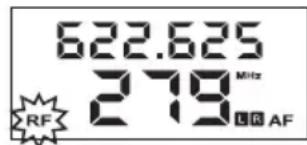
iv. Press the Scan button to select the auto-scanned frequency and enter broadcast mode. The RF indicator in the display will flash, indicating that the selected frequency is being broadcast to the transmitter via the 2.4 GHz frequency (see image).
If the Scan button is not pressed after 5 minutes, the receiver will exit Scan mode and revert to the previously selected frequency.
v. Once the transmitter has synced with the receiver (see Setting Up the Transmitter below), the receiver will automatically stop broadcasting the selected frequency and the RF indicator will stop flashing. You can exit broadcast mode by pressing the Scan button to return to normal operation, or press the L/R, Delay, or SQ buttons to exit broadcast mode and enter the selected function.
- To manually select a frequency:
i. Press the Freq button once to enter manual frequency selection mode. The RF frequency and channel will flash on the Display.
ii. With the frequency flashing, press the Up/Down buttons to increase (+) or decrease (-) the frequency and corresponding channel.
iii. When an acceptable frequency is found, press Freq a second time to complete manual frequency selection and enter broadcast mode. The RF indicator will flash in the display, signaling that the selected frequency is being broadcast to the transmitter via the 2.4 GHz frequency (see image, above).
iv. Once the transmitter has synchronized with the receiver (see Setting Up the Transmitter below), the receiver will automatically stop broadcasting the selected frequency and the RF indicator will stop flashing. You can exit broadcast mode by pressing the Scan button to return to normal operation, or press the L/R, Delay, or SQ buttons to exit broadcast mode and enter the selected function.
-
The transmitter must be in Sync mode to accept frequency changes made by the receiver.
-
The receiver will stop sending frequency data if it receives an RF signal lock from the transmitter, or if it receives no RF signal lock after 10 minutes.
Delay Line Adjustment
- Press the Delay button once to enter delay line adjustment mode. The measurement units on the display will flash. By default, the selected measurement unit when the Delay button is first pressed is milliseconds (ms). To change the measurement unit:
i. Press Delay a second time to change the unit to feet (ft.).
ii. Press Delay a third time to change the unit to meters (m).
iii. If Delay is pressed a fourth time, the measurement units will stop flashing and delay line adjustment mode is exited. To start over, press Delay again.
-
Once the measurement unit is selected, use the Up/Down buttons to increase (+) or decrease (-) the delay parameter. Increasing the delay amount greater than zero should cause the Delay On icon in the Display to light.
-
Single press the Up/Down buttons to adjust the value incrementally.
-
Press and hold the Up/Down buttons to continually adjust the value.
-
When the desired value is reached, press the Delay button to exit delay line adjustment mode. You can also press the Scan, Freq, L/R, Delay, or SQ buttons to exit delay line adjustment mode and enter that respective mode.
Setting Up the Transmitter
- Use a standard XLR cable or 1/4 (6.35 mm) cable (not included) to connect your mixer or other audio source to the transmitter's Combo Inputs.
- Use the included power adapter to connect the transmitter's power connector to your power source. Press the Power Switch to turn the transmitter on.
- To enter frequency selection mode, first press the Freq button on the transmitter.
i. Press once for Channel 1. The Channel 1 frequency will flash on the Display.
ii. Press a second time within 10 seconds of the first press to enter frequency selection mode for Channel 2. The Channel 2 frequency will flash on the Display.
iii. Press a third time within 10 seconds of the second press to exit manual frequency selection mode.
Next, set the transmitter's frequency using one of the following methods:
- To automatically synchronize the transmitter with the receiver's selected frequency:
i. Make sure the receiver is powered on and within 3 feet (1 meter) of the transmitter.
ii. Press the Sync button on the transmitter. The Sync indicators will flash on both channels in the Display, and the transmitter is ready to receive channel and frequency information from the receivers.
iii. With Sync flashing on the transmitter, press the Freq button on the receiver you want to synchronize until the RF indicator flashes on the Display (see image). When the RF indicator flashes, the receiver will enter broadcast mode and transmit channel and frequency information via the 2.4 GHz frequency.

If the transmitter has not received a frequency from the receiver after 5 minutes, it will exit Sync mode and revert to the last set frequency. You can also press the Sync button a second time while the Display is flashing to exit automatic frequency selection mode.
iv. When synchronization is complete and the receiver exits broadcast mode, the RF indicator will stop flashing on the receiver and the Sync indicator will stop flashing and disappear on the synchronized channel of the transmitter.
Important: If you are setting up a system using multiple receiver-transmitter pairs, set up each receiver one at a time and keep each receiver powered on as you set up additional units. This will prevent each pair from automatically selecting the same channel.
- To manually select a frequency:
i. With Channel 1 or Channel 2 flashing on the transmitter (see above), press the Up/Down buttons on the transmitter to increase (+) or decrease (-) the frequency and corresponding channel.
ii. When an acceptable frequency is found, press Freq again to exit manual frequency selection mode. The frequency will stop flashing, and the new RF channel is now active.
- Press the Vol button until the volume level of the appropriate channel flashes in the Display. Use the Up/Down buttons to adjust the volume level. When finished, press the Vol button until the display stops flashing.
Features
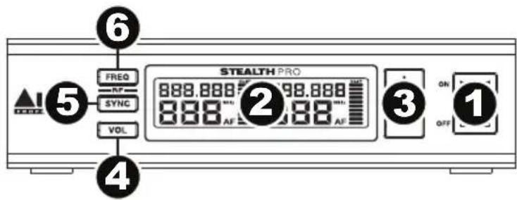
Transmitter
Front Panel
- Power Switch: This switch tums the transmitter on or off.
- Display: This display shows the current channel, frequency, and AF volume level. See Display for more information.
- Up/Down (+ / - ) : Use these buttons to adjust the selected value on the Display.
- Volume: Press this button to adjust the incoming signal level.
- Sync: Press this button to automatically synchronize with the receiver. See Operation for more information.
- Freq: Press this button to manually select the RF frequency and channel for each stereo channel. The selected channel will flash on the Display. See Operation for more information.
i. Press once to manually adjust the Left Channel.
ii. Press a second time to manually adjust the Right Channel.
iii. Press a third time to exit manual frequency adjustment mode.
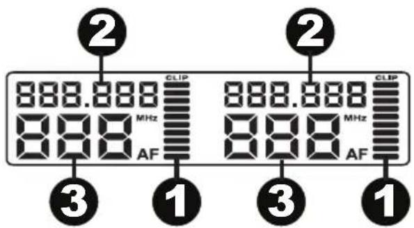
Display
- AF: This meter shows the current audio signal level received from the Combo Inputs.
- Frequency: This is the current RF frequency in MHz.
- Channel (region specific): This is the current RF channel number. The number of available channels depends on your region.
Rear Panel
- Power Connector: Connect the included 12 V, 1.0 A power adapter here.
- Combo Inputs: Connect balanced or unbalanced 1/4 (6.35 mm) or XLR line-level sources here.
- Mono/Stereo Select: Adjust this switch to change the wireless signal that is sent to the receiver to be either mono or stereo.
- Antenna Terminals: Attach the BNC antennas to these connectors. Place the antennas in a vertical position for best results in transmitting the wireless signal. If the wireless signal quality is poor, change the position of the antennas.
Receiver
Top Panel
- Antennas (BNC): The wireless receiver's 2 antennas receive the signal that is sent from the transmitter. Place the antennas in a vertical position for best results in transmitting the wireless signal. If the wireless signal quality is poor, change the position of the antennas.
- Display: This display shows the current channel, frequency, and other settings. See Display for more information.
- Mount: Use this M10 mounting point to attach the receiver to a loudspeaker.
- Up/Down (+ / - ) : Use these buttons adjust the selected value on the Display.
- Scan: Press this button to automatically scan for the best available RF frequency and channel. See Operation for more information.
- Freq: Press this button to manually select the RF frequency and channel. See Operation for more information.
- L/R: Selects which stereo channel the receiver receives from the transmitter. This only applies if both receivers are being used in a stereo application. On both receivers, set the switch to the appropriate positions that match the L/R speaker configuration.
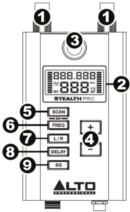
- Delay: Press this button to adjust the time alignment of loudspeakers depending on their position. See Operation for more information.
i. Press once to enter delay line adjustment mode. The selected measurement unit will flash on the Display. The default measurement unit is milliseconds (ms)
ii. Press a second time to change the measurement unit to feet (ft.).
iii. Press a third time to change the measurement unit to meters (m).
iv. Press a fourth time to exit delay line adjustment mode.
- SQ (Squelch): Sets an RF signal level limit. Signals must come in above that noise limit in order to pass through the squelch filter. Higher settings allow for greater noise reduction and dynamic range, but a setting that's too high can cause intentionally quieter sounds to be silenced along with the noise. Be sure to experiment with different settings to find an optimal balance.
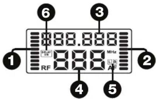
Display
- RF: During the scan process, the RF meter shows the relative amount of RF noise on each scanned frequency. A low meter value means that the RF channel is clear, while a high RF meter value indicates that there is a significant amount of RF interference on the currently scanned channel.
- AF: This meter shows the current audio signal level sent from the receiver's Audio Output.
- Frequency: This is the current RF frequency in MHz.
- Channel (region specific): This is the current RF channel number. The number of available channels depends on your region.
- L/R: Indicates which stereo channel the receiver is receiving from the transmitter.
- Delay: Indicates whether the Delay function is on or off and displays the selected measurement unit. The available measurement units are milliseconds (ms), feet (ft.), and meters (m).
Rear Panel
- Power Connector: Connect the included 12 V, 1.0 A power adapter here.
- Audio Output (mini-XLR): Use the included mini-XLR to XLR cable to connect this balanced output to your loudspeaker.

Troubleshooting
| Problem | Solution |
| The receiver does not produce any sound. | Make sure the receiver's power adapter is properly connected to the power connector and a power source. |
| Make sure the receiver's audio output is properly connected to your mixer, amplifier system, etc. Also, make sure the volume controls on your mixer and speaker are turned up. | |
| Make sure both the transmitter and receiver are set to the same RF frequency and channel. | |
| Make sure the receiver and transmitter are within 200 feet (60 meters) and have a clear line of sight. Also, make sure the receiver is not immediately near any metal objects or devices that could cause RF interference (other wireless systems, TVs, radio, etc.). | |
| Adjust the squelch control setting. A higher squelch setting provides better protection against interference but may also reduce signal range. Choose a setting that most effectively mutes interference yet allows the true signal to pass through. If poor signal quality requires a higher squelch setting, try to eliminate the interference or switch the transmitter/receiver channel to avoid a loss of signal range. | |
| There is audible interference in the transmission. | Make sure the receiver and transmitter are within 200 feet (60 meters) and have a clear line of sight. Also, make sure the receiver is not immediately near any metal objects or devices that could cause RF interference (other wireless systems, TVs, radio, etc.). |
| Change the RF frequency and channel on both the transmitter and receiver (to the same channel). | |
| If you are using multiple transmitter-receiver pairs, use only one pair at a time, or make sure the pairs are not using the same or adjacent frequencies. | |
| Adjust the squelch control setting. A higher squelch setting provides better protection against interference but may also reduce signal range. Choose a setting that most effectively mutes interference yet allows the true signal to pass through. If poor signal quality requires a higher squelch setting, try to eliminate the interference or switch the transmitter/receiver channel to avoid a loss of signal range. | |
| The signal is distorted. | Make sure the receiver is not immediately near any metal objects or devices that could cause RF interference (other wireless systems, TVs, radio, etc.). |
| Make sure the receiver antennas do not touch each other. | |
| Keep any connected audio cables away from the antennas. | |
| Make sure no other devices are sending signals on the same RF frequency and channel. | |
| Change the RF frequency and channel on both the transmitter and receiver (to the same channel). |
Technical Specifications
Specifications are subject to change without notice.
Transmitter
| Frequency Response | 50 Hz – 17 kHz, ±3 dB |
| Frequency Range | 540–570 MHz (USA), 614–640 MHz (EU), 606–640 MHz (UK) |
| Channels | Up to 700 selectable UHF frequency bands (regional dependent) |
| Wireless Range | 330 feet (100 meters) |
| Bandwidth | 50 KHz |
| Oscillation Type | PLL |
| Frequency Stability | ±0.005% |
| Frequency Deviation | ±20 kHz |
| Inputs | 2 combo XLR and 1/4" (6.35 mm) TRS |
| Power | 12 V, 1.0 A |
| Dimensions (width x depth x height) | 6.75" x 5.7" x 1.75" 172 mm x 145 mm x 45 mm |
| Weight | 1.6 lb. 0.73 kg |
Receiver
| Sensitivity | -100 dBm |
| Image Rejection | >70 dB |
| T.H.D. | <0.05% @ 1 KHz |
| Outputs | 1 mini-XLR |
| Output Impedance | 600 ohm balanced |
| Power | 12 V, 1.0 A |
| Dimensions (width x depth x height) | 2.75" x 1.13" x 4.5" 70 mm x 29 mm x 115 mm |
| Weight | 0.6 lb. 0.3 kg |
Trademarks and Licenses
Alto Professional is a trademark of inMusic Brands, Inc., registered in the U.S. and other countries. All other product or company names are trademarks or registered trademarks of their respective owners.
altoprofessional.com
- User Guide (English)
- Introduction
- Box Contents
- Support
- Important Safety Precautions
- Sound Level
- Quick Start
- Assembly
- Mounting the Receiver to the Loudspeaker
- Rack-Mounting One Transmitter
- Rack-Mounting Two Transmitters
- Connection Diagrams
- Example 1 - Mono Operation
- Example 2 - Stereo Operation
- Operation
- Setting Up the Receiver
- Frequency Selection
- Delay Line Adjustment
- Setting Up the Transmitter
- Features
- Transmitter
- Front Panel
- Display
- Rear Panel
- Receiver
- Top Panel
- Troubleshooting
- Technical Specifications
- Trademarks and Licenses
- altoprofessional.com
Brand : ALTO
Model : Stealth Pro
Category : Hi-fi system