HD 91004 Cage Classic - Pressure washer Kärcher - Free user manual and instructions
Find the device manual for free HD 91004 Cage Classic Kärcher in PDF.
| Product type | Industrial high-pressure cleaner |
| Brand | Kärcher (WOMA GmbH) |
| Model | HD 91004 Cage Classic |
| Max. operating pressure | 1500 bar |
| Max. flow rate | 45 l/min |
| Maximum fluid temperature | 95 °C |
| Max. recoil force without body support | 150 N |
| Max. recoil force with body support | 250 N |
| Weight (without attachments) | 3,3 kg |
| Length (without lance) | Approx. 340 mm |
| Height | Approx. 200 mm |
| Width | Approx. 50 mm |
| High-pressure hose connection | 9/16"-18 UNF-LH or M24x1,5-24°DKO |
| Lance/lance tube connection | 9/16"-18 UNF-LH |
| By-pass connection | G 3/8" |
| Control | Mechanical by-pass |
| Safety | Trigger lock, manual emergency stop |
| Routine maintenance | Daily inspection, visual check, cartridge replacement every 12 months |
| Spare parts | Original WOMA GmbH parts (cartridge kit no. 9.919-046.0) |
| Compatible accessories | Lances, turbo nozzles, Orbimaster, splash protection, body support |
| Required water quality | WOMA directive: hardness 1-20 °H, pH 6.5-9.5, chlorides < 100 mg/l |
| Intended use | Cleaning and blasting of surfaces (steel, concrete) with high-pressure jet |
Frequently Asked Questions - HD 91004 Cage Classic Kärcher
User questions about HD 91004 Cage Classic Kärcher
0 question about this device. Answer the ones you know or ask your own.
Ask a new question about this device
Download the instructions for your Pressure washer in PDF format for free! Find your manual HD 91004 Cage Classic - Kärcher and take your electronic device back in hand. On this page are published all the documents necessary for the use of your device. HD 91004 Cage Classic by Kärcher.
USER MANUAL HD 91004 Cage Classic Kärcher
natural_image
Close-up of a black and silver industrial tool with a curved handle and cylindrical shaft (no visible text or symbols)Deutsch 3
English 12
Français 20
Italiano 29
Nederlands 38
Español 47
Português 56
Dansk 65
Norsk 73
Svenska 81
Suomi 89
Ελληνικά 97
Türkçe 106
Русский 114
Magyar 124
Čeština 133
Slovenščina 141
Polski 149
Românește 158
Slovenčina 167
Hrvatski 176
Srpski 184
Български 192
Eesti 202
Latviešu 210
Lietuviškai 218
Українська 226
text_image
Exploded view diagram of a mechanical device with numbered parts for identification and assembly reference.Inhalt
text_image
Exploded view diagram of a spray gun with numbered parts and labeled connectors1.1 Information on these operating instructions
These operating instructions were created according to the Machinery Directive 2006/42/EC guideline. They allow safe and efficient handling of the product HP-DG.
The original operating instructions were created in German.
Read these operating instructions before using the product for the first time, adhere to the instructions contained therein and store these operating instructions for later reference or subsequent owners of the product.
1.2 Manufacturer
WOMA GmbH
Werthauser Straße 77-79
47226 Duisburg
Germany
Ph: + 49 2065-304-0
Our worldwide Service department is available for all technical information on WOMA products and their technical system applications.
Please contact the WOMA Service department, the agent responsible or the manufacturer factory if you have problems with our product. We will be happy to help you.
WOMA GmbH
Werthauser Straße 77-79
47226 Duisburg
Germany
Ph: + 49 2065-304-0
Fax: +49 2065-304-200
Email: service@woma.kaercher.com
www.woma-group.com
Note
Quick assistance and correct order processing is only possible when you can tell us your order number and product serial number. We recommend that you enter this information here:
- Order number:
- Serial number:
1.4 Formal information on these operating instructions
Copyright, 2019©
All rights reserved.
Publication of this document and any document excerpts is prohibited without the permission of WOMA GmbH.
1.5 Illustration conventions
1.5.1 Acton steps in the specified sequence
Action steps to be executed are shown as a numbered or alphabetic list. The sequence of the steps must be maintained.
Example:
- Action step 1
- Action step 2
a Action sub-step a
b Action sub-step b
1.5.2 Itemizations
Lists and action steps without a mandatory sequence are shown as a bullet list.
Example:
- Point 1
- Point 2
- Sub-point 1
- Sub-point 2
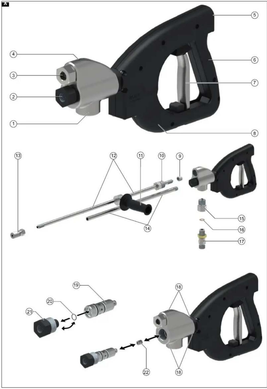
1.6 Product elements
Figure A see page 2
①High-pressure hose connection
②Bypass connection
③Spray tube/spray lance high-pressure connection
④Pressure housing
⑤Body support connection
⑥Handle
⑦Trigger
⑧Trigger catch
⑨Pressure ring
⑩Pressure screw
⑪Handle for spray tube/spray lance (accessory)
⑫Spray tube/spray lance (accessory)
⑬ Nozzle holder/water tool (accessory)
⑭Bypass line (accessory)
⑮Adapter (accessory)
⑯Seal (accessory)
⑰Hose connection (accessory)
⑱Leakage hole
⑲Cartridge (pressure housing)
⑳Seal (pressure housing)
②1 Bypass screw (pressure housing)
②2Spring (pressure housing)
1.7 Scope of delivery
Product
- Operating instructions
Check the contents for completeness. Please contact your dealer if the contents are incomplete or shipping damage is present.
1.8 Abbreviations and definitions
In the following sections, the term spray device is used to describe an assembly consisting of a trigger device (high-pressure gun), a spray tube/spray lance and a water tool.
2 Safety
In addition to the notes in the operating instructions, the general safety regulations and accident prevention guidelines applicable by law must be adhered to.
2.1 Warning notices
Warning notices prevent personal injury and material damage when observed.
A warning notice contains the following elements and information:
Danger symbol ⚠
The danger symbol identifies warning notices for preventing personal injury.
Keyword
The hazard level is indicated by the keyword.
Source of danger
The source of danger specifies the cause of the hazard.
Possible consequences of failure to observe
Possible consequences of failing to observe a warning notice are e. g. crushing injuries, burns or other severe injuries.
Measures / Prohibitions
Measures / Prohibitions specifies actions that must be taken to avoid the hazard or that are prohibited in order to avoid the hazard.
2.2 Representation of warning notices
DANGER
Source of danger
Possible consequences of failure to observe
Measures / Prohibitions
2.2.1 Hazard levels
△DANGER
- Indication of an imminent threat of danger that will lead to severe injuries or even death.
⚠ WARNING
- Indication of a potentially dangerous situation that may lead to severe injuries or even death.
△CAUTION
- Indication of a potentially dangerous situation that may lead to minor injuries.
ATTENTION
- Indication of a potentially dangerous situation that may lead to damage to property.
2.3 Representation of notes
Note
Indication of useful and important information or suggestions for improving safety when handling the product.
2.4 Personnel qualifications
The personnel must be appropriately qualified for the respective use of the product.
The owner must clearly defined the areas of responsibility and the personnel monitoring systems.
Ensure sufficient personnel knowledge through appropriate training and instruction.
2.4.1 Operating personnel
Operating personnel are persons commissioned by the owner to operate the product and who are sufficiently trained in the operation and functionality of the product.
The operating personnel must be sufficiently trained in the operation and functionality of the product, must be able to recognize any hazards that may occur and be capable of preventing these hazards through appropriate protective measures.
The operating personnel must be able to recognize any hazards in time and be able to implement the prescribed protective measures accordingly.
The operating personnel is obliged to immediately notify the owner/operator of any safety-relevant changes in the product.
2.4.2 Maintenance personnel
Maintenance personnel are persons commissioned by the owner to perform maintenance work on the product. Maintenance personnel are untrained but have been instructed in inspection and maintenance work, e.g. oil changes, checking screwed connections etc.
The maintenance personnel must be familiar with the operation and functionality of the product, must be able to recognize any hazards that may occur and be capable of preventing these hazards through appropriate protective measures.
The maintenance personnel is obliged to immediately notify the owner/operator of any safety-relevant changes in the product.
2.4.3 Trained technical personnel
Trained technical personnel are persons trained by WOMA GmbH to perform inspection, maintenance and servicing work and who have received the necessary information in the form of a service manual during their training. Trained technical personnel are familiar with the operation and functionality of the product and are able to recognize any hazards that may occur and be capable of preventing these hazards through appropriate protective measures.
2.5 Cables and hoses
△DANGER
Contact with high-pressure water jets can cause irreversible injuries or even death. Tripping over, threading or catching the cables and hoses can lead to uncontrolled changes in the direction of the high-pressure water jet.
● Cables and hoses must not be allowed to form loops.
- Remove unused cables and hoses from the work area.
⚠ WARNING
Contact with a high-pressure water jet escaping from a pressurised, damaged hose can cause irreversible injuries or even death.
- Check the cables and hoses for damage each time before use. Immediately replace damaged cables and hoses.
- Do not continue using cables, hoses or extensions if they have been driven over, crushed, pulled or excessively loaded in a similar manner. This also applies when no damage is visible.
● Protect cables and hoses from heat and sharp edges. - Use hose catching fixtures. These must be securely fastened.
2.6 Water connection
⚠ WARNING
Contact with high-pressure water jets escaping from pressurised hoses and screw connections can cause irreversible injuries or even death.
- Use only hoses and accessories approved for the maximum operating pressure of the high-pressure water jet machine.
- Check the screw connections of all connection hoses for leaks before starting the device.
- Do not use a hose connection with a damaged thread.
2.7 Usage
2.7.1 Work area
△DANGER
Contact with high-pressure water jets can cause irreversible injuries or even death.
- Do not direct high-pressure water jets towards humans, animals or electrical equipment.
- Never work alone! For safety reasons, a second person must always be present when using the safety device, who is able to shut down the high-pressure water jet machine in the case of an emergency and obtain help if necessary.
- No persons except the operating personnel may be present within a 10 m radius of the spray device when spraying.
- The spray device work area and the general work area must be fully visible.
- Secure the spray device work area in a clearly visible manner against unauthorised access while spraying. Erect warning signs and cordon off the area.
- Depending on the surface characteristics, the ground can become slippery due to the spray mist or emitted water. Maintain a solid and safe footing when working with a water jet.
- Spray mist impairs direct visibility. Take the local conditions into account and watch out for other persons when working with a water jet.
- The operating personnel must be secured against falling when spraying on scaffolding.
- The operating personnel must be secured by a retaining device (e.g. straps, ropes) when spraying in enclosed spaces (e.g. tanks or autoclaves). Ensure an additional supply of sufficient fresh air.
- Adhere to the respective safety instructions when using the spray device in hazard zones (e.g. service stations).
- The spray device may not be operated in explosive atmospheres.
2.7.2 General usage information
△DANGER
Incorrectly used high-pressure water jets can be dangerous and contact with high-pressure water jets can cause irreversible injuries or even death.
- Do not use spray equipment shorter than 750 mm (measured from trigger to nozzle). A danger of injury exists when working with short spray lances because your hand may come into contact with the high-pressure jet.
- Use the device only in the specified correct manner (see chapter 3 Intended use).
- Check the product and work equipment prior to each use to make sure it is safe and working correctly (see chapter 6 Startup). Do not use a damaged spray device.
● Never lock the trigger of the product.
- The impact of the high-pressure water jet can release particles or larger elements from the surface being cleaned. These are strongly accelerated and can injure the operating personnel. Wear the prescribed personal protective equipment.
- Do not use the high-pressure water jet machine and the spray device when you are tired, medically impaired or under the influence of alcohol or medication.
- Never use liquids containing solvents or undiluted acids and solvents. This includes e.g. petrol, paint thinner or heating oil. The spray mist is highly flammable, explosive and poisonous.
● Materials containing asbestos or other substances harmful to health may not be sprayed.
2.7.3 Temperature
⚠ WARNING
Escaping high-pressure water can cause burns or scalding.
● Wear personal protective equipment.
- Do not touch any hot surfaces of the spray device when using hot water.
- Install a handle for protection (see the WOMA product range).
- Allow the spray device to cool down after hot water operation or flush the spray device using cold water operation.
- The fluid can heat up in cold water operation due to depressurisation of the high-pressure water. Do not touch any hot surfaces of the spray device.
2.7.4 Noise
⚠ WARNING
The high nozzle outlet speed of the high-pressure water jet results in a high noise level that can cause discomfort or hearing damage (e.g. tinnitus) to persons in the immediate vicinity. A continuously high noise level can result in deafness.
● Wear the prescribed personal protective equipment.
- High noise levels can impair vocal communication and impair or prevent your ability to perceive acoustic warning signals. Never work alone. A second person must be present outside the work area.
2.7.5 Recoil forces
⚠ WARNING
The recoil forces occurring when working with a water jet present a risk of falling.
- Maintain a solid and safe footing. Do not work on ladders.
- Hold the spray device by the specified handles with both hands.
- Select the nozzle diameter for manually performed spray work so that the longitudinal recoil force does not exceed 250 N. The spray device must be equipped with a body support (see the WOMA product range) if the recoil force exceeds 150 N.
- When simultaneously operating multiple spray devices from a single high-pressure water jet machine, be aware of the changing recoil forces. The recoil forces occurring at the other spray devices must not change by more than 15% when opening or closing a spray device.
Note
The recoil forces present are specified in the WOMA product data sheets for the nozzles use, which can be requested from WOMA GmbH (see chapter 1.3 Service).
2.7.6 Vibration
△CAUTION
Hand-arm acceleration values exceeding 2.5 m/s ^2 can occur, depending on the spray device used. Longer periods of use may lead to poor blood circulation in the hands due to vibration.
A general maximum period of use cannot be specified, because this depends on several influencing factors:
- Personal tendency to suffer from poor circulation (symptoms such as frequently cold fingers, tingling sensation in the fingers etc.).
- Low ambient temperature. Wear warm gloves to protect your hands.
- Grasping tightly reduces the circulation of blood in the hands.
- Working without interruption amplifies the effects of vibration induced blood circulation problems.
Note
We recommend consulting a doctor if corresponding symptoms occur repeatedly after regular, long-duration use of the spray device.
2.8 Protective gear
⚠ WARNING
Risk of injury through incorrect or incomplete protective gear
- The operating personnel must wear protective clothing specially designed for use with high-pressure water jet machines. CE-certified protective clothing made of Dyneema fibres provides tested protection when using rigid or rotating nozzles at pressures of up to 3000 bar / 43,511 psi.
- All the following protective clothing must be worn when working and lingering in the work area:
– Hard hat with protective visor
- Safety goggles
– Encapsulated hearing protection
- Protective gloves
- Protective jacket, protective trousers
– Special safety boots with metatarsal protection
2.9 Safety devices
Safety devices protect the operating personnel and may not be disabled or functionally circumvented.
The product is equipped with a trigger safety catch that prevents the trigger from being actuated unintentionally.
● Never lock the trigger.
- Do not block or modify the trigger catch.
3 Intended use
This product is used for actuating manually operated spray devices from WOMA GmbH, used at permissible operating pressures of up to 1100 bar.
In conjunction with a high-pressure water jet machine, spray tube / spray lance and a water tool, this product is designed for targeted application of a high-pressure fluid to a surface for the purpose of removing, cleaning etc. various surfaces and materials such as steel, concrete etc. This can be achieved using various different water tools from WOMA GmbH.
This product is only to be used with water conforming to the WOMA water quality guideline (see Chapter 12.1 Water quality guideline). The maximum permissible fluid volume flow rate is 45 l/min.
Please check the safety devices on the product each time before use (see chapter 6 Startup).
Intended use also includes using only original spare parts from WOMA GmbH.
Any use other than, or beyond the specified intended use is regarded as incorrect use.
Observe the safety instructions and warning notices.
3.1 Foreseeable misuse
The device is equipped with a trigger safety catch. This prevents unintentional actuation of the trigger.
● Never lock the trigger.
- Do not block or modify the trigger catch.
- Do not use spray equipment shorter than 750 mm (measured from trigger to nozzle).
- Do not use the spray device for cleaning the high-pressure water jet machine or for mechanically loosening contamination or baked deposits (e.g. when cleaning a cement kiln).
- Do not use the spray device as a lever (crowbar).
- Never use liquids containing solvents or undiluted acids and solvents for spraying. This includes e.g. petrol, paint thinner or heating oil. The spray mist is highly flammable, explosive and poisonous.
● Materials containing asbestos or other substances harmful to health may not be sprayed.
4 Environmental protection

The packing materials can be recycled. Please dispose of packaging in accordance with the environmental regulations.

Electrical and electronic appliances contain valuable, recyclable materials and often components such as batteries, rechargeable batteries or oil, which - if hand- or disposed of incorrectly - can pose a potential threat human health and the environment. However, these components are required for the correct operation of the appliance. Appliances marked by this symbol are not al- ed to be disposed of together with the household rub-
Notes on the content materials (REACH)
Current information on content materials can be found at: www.kaercher.com/REACH
5 Installation
5.1 Safety instructions
⚠ WARNING
Risk of injury from the high-pressure water jet
A high-pressure water jet can escape from a pressurised high-pressure water jet machine.
Switch off the high-pressure water jet machine and secure it against being switched on again before installing the product.
Ensure that all components of the high-pressure water jet machine are depressurised.
ATTENTION
Improper installation
Improper installation with damaged or dirty components can lead to malfunctions and damage to the product.
Perform a visual inspection of all product elements before installation.
All threads must be clean and undamaged.
The sealing surfaces of mating components must not have any scratches or scoring.
5.2 Installing the spray tube/spray lance
- Release the pressure screw from the pressure housing and remove together with the pressure ring (see illustration on page 2).
- Push the pressure screw onto the spray tube/spray lance.
- Coat all threads with installation paste before installation (see Chapter 12.2 Consumables).
- Unscrew the pressure ring (left-hand thread) until 1-2 threads are visible.
- Push the spray tube/spray lance with the pressure screw into the pressure housing.
- Screw the pressure screw into the pressure housing (30 mm) and tighten to a torque of 160 Nm.
- When cleaning surfaces (e.g. cleaning concrete), install the splash guard (see Chapter 13 Accessories) on the spray tube/spray lance.
- Screw the nozzle holder or other water tool onto the spray tube/spray lance and tighten to a torque of 100 Nm unless specified otherwise.
Major characteristics of the water tools
- Water tools (e.g. nozzles, turbo nozzle, Orbimaster, Speedy) used on manually operated spray devices from WOMA GmbH may have multiple nozzle outlet openings. These may be spotlight nozzles or flat jet nozzles. Motor-driven rotation, or self-driven rotation through angled nozzles is possible (see the WOMA product range).
- Water tools extend the range of possible uses for the spray device. Further information is available from your WOMA sales partner.
5.3 Installing the bypass line
- Coat all threads with installation paste before installation (see Chapter 12.2 Consumables).
- Screw the bypass pipe or bypass hose connection into the pressure housing (32 mm) and tighten onto the bypass connection to a torque of 100 Nm (see illustration on page 2).
5.4 Installing the hose connection
(see illustration on page 2)
Note
Take care to ensure that only hoses approved for the maximum operating pressure are used.
- Coat all threads with installation paste before installation (see Chapter 12.2 Consumables).
- Screw the adapter (material number 9.918-624.0) into the pressure housing and tighten to a torque of 130 Nm.
- Fit the seal (O-ring) in the adapter.
- Screw the hose connection into the adapter and tighten to a torque of 130 Nm.
- Connect the high-pressure water jet machine to the secured spray device using a suitable high-pressure hose.
6 S t a r t u p
6.1 Safety instructions
⚠️DANGER
Risk of injury from the high-pressure water jet
Contact with high-pressure water jets can cause irreversible injuries or even death.
Do not direct high-pressure water jets towards humans, animals or electrical equipment.
Ensure that the product is correctly installed before use (see chapter 5 Installation).
Due to the potential hazards (e.g. recoil, cutting effects of the water jet etc.) be sure to use the product only in the intended manner (see chapter 3 Intended use).
The product may only be operated by personnel who have been trained for this and who have been instructed in the potential hazards (see chapter 2.4 Personnel qualifications).
Wear the prescribed personal protective equipment when spraying (see chapter 2.8 Protective gear).
Note
Do not operate the product at temperatures below 0 °C.
6.2 Before switching on the high pressure water jet machine
The product is correctly installed and connected to the high-pressure water jet machine. The high pressure water jet machine is not switched on.
Perform the following steps each time before switching on the high water pressure, i.e. when the high pressure pump is stationary and pressurised:
- Vent the entire high pressure water jet machine using the filter and the vent hose on the high pressure pump.
- Rinse the high pressure water jet machine, including the high pressure hose, with fresh water while the product is depressurised.
- Check the bypass line on the water outlet.
Water must be expelled from the bypass line when the product is not actuated. - Check that the trigger and the trigger catch are functioning smoothly and freely.
The trigger must return automatically to its original position after actuation and engage into the trigger. It should only be possible to actuate the trigger when the trigger catch is actuated once again. - Check the product condition for differences from its condition on delivery.
Has the position of the pressure point changed, for example? When switching from Trigger actuated to Trigger not actuated, the water volume flow in the bypass line must be expelled immediately.
Note
Do not use the product if the checks are unsuccessful. In this case, have a safety inspection conducted (see chapter 9.4 Service).
6.3 Before starting spraying
The product is correctly installed and connected to the high-pressure water jet machine.
The high-pressure water jet machine is switched on.
Note
Depressurised jet liquid flows out of the bypass line when the high-pressure water jet machine is switched on and the product is not actuated.
Before starting work with the product using high water pressure, perform the following checks:
- Check the bypass line on the water outlet. Water must be expelled from the bypass line when the product is not actuated.
- Actuate the product under high pressure several times in a safe area and check the valves on the bypass and the leakage holes for leaks.
- Check that the trigger and the trigger catch are functioning smoothly and freely.
The trigger must return automatically to its original position after actuation and engage into the trigger. It should only be possible to actuate the trigger when the trigger catch is actuated once again.
- With the help of the supervisor, check whether the planned working pressure of the high pressure water jet machine is reached.
Note
Do not use the product if the checks are unsuccessful or if an abnormality or unexpected situation is determined. In this case, have a safety inspection conducted (see chapter 9.4 Service).
6.4 Starting up the product
The product is correctly installed and connected to the high-pressure water jet machine.
The high-pressure water jet machine is switched on. Product checks in accordance with Chapter 6.2 Before switching on the high pressure water jet machine and Chapter 6.3 Before starting spraying are successful.
Note
Depressurised jet liquid flows out of the bypass line when the high-pressure water jet machine is switched on and the product is not actuated.
- Actuate the trigger safety catch. Do this by pressing the trigger safety catch down.
- Actuate the trigger.
Actuating the trigger closes the bypass line and causes the spray fluid to be emitted under pressure out of the nozzle of the water tool.
Note
Non-corrosion resistant materials can be corroded by the emitted high-pressure water jet.
7 Shutting down
7.1 Safety instructions
DANGER
Risk of injury from the high-pressure water jet
A high-pressure water jet can escape from a pressurised high-pressure water jet machine.
Ensure that all components of the high-pressure water jet machine are depressurised after shutting down the product.
△CAUTION
Hot surfaces
Touching the surface of the product can cause burns or scalding.
Wear personal protective equipment.
Do not touch any elements of the product after using it with hot water.
Allow the product to cool down after hot water operation or flush the spray device using cold water operation.
7.2 Shutting down the product
Note
Depressurised jet liquid flows out of the bypass line when the high-pressure water jet machine is switched on and the product is not actuated.
- Release the trigger. The trigger automatically locks onto the trigger catch.
- Check that the trigger catch is correctly engaged by actuating the trigger.
- Switch off the high-pressure water jet machine and secure it against being switched on again.
- The high-pressure system must be depressurised. To do this, completely discharge all residual pressure.
- Disconnect all supply lines from the product in the reverse order (see Chapter 5 Installation).
8 Storage
The following applies to this product and, unless specified otherwise, to all other water tools:
● Clean after finishing work.
- Store in a frost-protected place.
- For long-term storage, blow out the product with compressed air and conserve using a suitable preservative.
9 Maintenance and servicing
9.1 Safety instructions
⚠️DANGER
Risk of injury from the high-pressure water jet
A high-pressure water jet can escape from a pressurised high-pressure water jet machine.
Switch off the high-pressure water jet machine and secure it against being switched on again before performing any work on the product.
Ensure that all components of the high-pressure water jet machine are depressurised.
⚠ WARNING
Improper servicing
The use of third-party parts can impair the functionality and safety of the high-pressure water jet machine.
Only use original spare parts from WOMA GmbH. The WOMA product range includes appropriate spare parts specially matched to the service life of the product. Further information is available from your WOMA sales partner.
The use of third-party spare parts is prohibited. Third-party spare parts often do not conform to the specifications and requirements. Third-party spare parts present an increased risk to the personnel and product. Functionality and safety can be impaired.
9.2 Care and cleaning
Note
Observe the manufacturer's safety data sheets when using cleaning agents.
- If necessary, perform general cleaning of the product.
9.3 Inspection
The operator performs the daily inspection and visual inspection of the product.
9.3.1 Daily inspection
- Perform daily product checks (see Chapter 6.2 Before switching on the high pressure water jet machine and Chapter 6.3 Before starting spraying).
9.3.2 Visual inspection
- Independent of the daily inspection, perform a visual inspection of all components of the spray unit before installation.
Do not use the product if deviations from its condition on delivery are determined. In this case, have a safety inspection to be conducted.
9.4 Service
9.4.1 Safety inspection
For safety reasons, safety inspection and service work may only be performed by service personnel from WOMA GmbH or by trained technical personnel (see chapter 2.4 Personnel qualifications).
- Have the product checked for the correct condition every 12 months.
9.4.2 Changing the cartridge
If additional water is expelled from the bypass line and/or the relief bores in the product when the spray unit is actuated then the cartridge in the pressure housing must be replaced.
A pre-assembled cartridge (material number 9.919-046.0) may be replaced by untrained technical personnel as follows.
ATTENTION
Improper installation
Improper installation with damaged or dirty components can lead to malfunctions and damage to the product.
Perform a visual inspection of all spray device elements before installation.
All threads must be clean and undamaged.
The sealing surfaces of mating components must not have any scratches or scoring.
A non-pre-assembled cartridge may only be replaced by trained technical personnel.
(See illustration on page 2)
- Release the bypass screw from the pressure housing and remove together with the cartridge.
- Remove the spring from the pressure housing and replace with a new spring.
- Disconnect the bypass screw from the cartridge.
- Remove the seal (O-ring) from the groove in the bypass screw.
- Fit the seal (O-ring) in the groove.
- Fit the bypass screw positively into the pre-assembled cartridge (material number 9.919-046.0).
- Coat the thread of the bypass screw with thread installation paste before installation (see Chapter 12.2 Consumables).
- Coat the fitting surfaces of the cartridge with anti-seize installation (see Chapter 12.2 Consumables).
- Screw the bypass screw with the cartridge into the pressure housing and tighten to a torque of 100 Nm.
10 Troubleshooting guide
10.1 Safety instructions
For safety reasons, malfunctions may only be corrected by Service personnel from WOMA GmbH or by trained technical personnel.
11 Technical data
| Material number 9.918-187.0 | ||
| Operating pressure max. bar 1500 | ||
| Medium temperature max. | °C | 95 |
| Flow rate max. | l/min | 45 |
| Recoil force without body support | N | 150 |
| Recoil force with body support | N | 250 |
| Weight (without attachments) approx. | kg | 3.3 |
| Length without spray lance approx. | mm | 340 |
| Height approx. | mm | 200 |
| Width approx. | mm | 50 |
| Connection for hose connection | M22x1.5-24°DKO | |
| High-pressure hose connection | 9/16"-18 UNF-LH M24x1.5-24°DKO | |
| Spray tube / spray lance connection | 9/16"-18 UNF-LH | |
| Bypass connection | G 3/8" | |
| Controller | Mechanical bypass | |
Subject to technical modifications.
12 Appendix
12.1 Water quality guideline
The limit values for the required water quality are an excerpt from the WOMA water quality guideline, which can be obtained from the WOMA GmbH (see Chapter 1.3 Service).
| Solid body content, max. | 200 mg/l |
| Total water hardness | 1 - 20 °H |
| CaO | 10 - 200 mg/l |
| CaCO_3 | 18 - 357 mg/l |
| Calcium hardness | 0.89 - 3.39 mmol/l |
| pH value | 6.5 - 9.5 |
| Base capacity (pH 8.2) | 0 - 0.25 mmol/l |
| Proportion of total dissolved material | 10 - 75 mg/l |
| Conductivity | 100 - 1000 μS/cm |
| Chloride (e. g. NaCl) | < 100 mg/l |
| Iron (Fe) | < 0.2 mg/l |
| Fluoride (F) | < 0.15 mg/l |
| Free chlorine (Cl) | < 1 mg/l |
| Copper (Cu) | < 2 mg/l |
| Manganese (Mn) | < 0.05 mg/l |
| Phosphate ( H_3PO_4 ) | < 50 mg/l |
| Silicate ( Si_xO_y ) | < 20 mg/l |
| Sulphate ( SO_4 ) | < 100 mg/l |
12.2 Consumables
| Description | Container Material number | |
| Thread installation paste | 500 g | 9.892-362.0 |
| Thread installation paste | 207 g | 9.740-194.0 |
| Anti-seize installation paste 45 | 0 g | 9.892-352.0 |
| Anti-seize installation paste 85 | g | 9.740-195.0 |
13 Accessories
The following sections show example accessory combinations for various different areas of application for the spray device. Further information is available from your WOMA sales partner.
The material numbers may deviate depending on their configuration. See the WOM A product range for more information.
13.1 Example configuration

text_image
Exploded view diagram of a spray gun with numbered parts and labeled connectors| Accessories | Variant | Material number | |
| 1 | Body support | 9.918-752.0 | |
| 2 | Installing the bypass | 500 mm length | 9.918-623.0 |
| 3 | Handle* | 6.025-300.0 | |
| 4 | Spray lance 1500 bar | 300–7000 mm in length | See WOMA product range |
| Spray lance 3000 bar | 300–6000 mm in length | See WOMA product range | |
| 5 | Splash guard | 9.871-040.0 | |
| 6 | Nozzle holder | 50–76 mm in length | 9.872-008.0, 9.872-183.0, 9.873-090.0, 9.878-291.0 |
| 7 | Orbimaster | See WOMA product range | |
| 8 | Turbo nozzle | See WOMA product range | |
| 9 | Speedy | See WOMA product range | |
| 10 | Handle | 9.871-675.0 | |
| 11 | Bypass hose | 1500 mm length | 9.887-970.0 |
| 12 | Bypass hose connection | Reduction 3/4" to 3/8" | 9.897-958.0 |
| 13 | Adapter | 1500 bar | 9.918-624.0 |
| 14 | Rotatable hose connection | 1500 bar | 9.872-437.0 |
| 15 | Hose connection | 1500 bar | 9.871-969.0 |
| 16 | Rotatable hose connection | 3000 bar | 9.872-640.0 |
| 17 | Hose connection | 3000 bar | 9.872-023.0 |
*) only useful for the bypass hose
Contenu
②Raccordement bypass
③Raccordement haute pression lance / tube de lance
④Carter de pression
⑤Raccordement soutien corporel
⑥Poignée
⑦Gâchette
⑳Joint (carter de pression)
②1 Vis bypass (carter de pression)
⑳Ressort (carter de pression)
(voir figure page 2)
text_image
Exploded view diagram of a spray gun with numbered parts and labeled connectors2.7.5 Forze repulsive
⚠AVVERTIMENTO
text_image
Exploded view diagram of a mechanical device with numbered parts and labeled connectorstext_image
Exploded view diagram of a spray gun with numbered parts and labeled partstext_image
Exploded view diagram of a spray gun with numbered parts and labeled partstext_image
Exploded view diagram of a mechanical device with numbered parts and labeled connectorstext_image
Exploded view diagram of a mechanical device with numbered components and labeled partsE-post: sales@woma.kaercher.com
www.woma-group.com
1.3 Service
E-post: service@woma.kaercher.com
www.woma-group.com
Merknad
text_image
Exploded view diagram of a spray gun with numbered parts and labeled parts| Tilbehør Varianter | Materialnummer | ||
| 1 | Kroppsstøtte | 9.918-752.0 | |
| 2 | Montere bypassledning | 500 mm lengde | 9.918-623.0 |
| 3 | Håndtak* | 6.025-300.0 | |
| 4 | Lanserør 1500 bar | 300–7000 mm lengde | se WOMAs produktprogram |
| Lanserør 3000 bar | 300-6000 mm lengde | se WOMAs produktprogram | |
| 5 | Sprutbeskyttelse | 9.871-040.0 | |
| 6 | Dysebærer/dyseholder | 50–76 mm lengde | 9.872-008.0, 9.872-183.0, 9.873-090.0, 9.878-291.0 |
| 7 | Orbimaster | se WOMAs produktprogram | |
| 8 | Turbodyse | se WOMAs produktprogram | |
| 9 | Speedy | se WOMAs produktprogram | |
| 10 | Håndtak | 9.871-675.0 | |
| 11 | Bypass-slange | 1500 mm lengde | 9.887-970.0 |
| 12 | Bypass-slangetilkobling | Reduksjon 3/4“ til 3/8“ | 9.897-958.0 |
| 13 | Adapter | 1500 bar | 9.918-624.0 |
| 14 | Dreibar slangetilkobling | 1500 bar | 9.872-437.0 |
| 15 | Slangetilkobling | 1500 bar | 9.871-969.0 |
| 16 | Dreibar slangetilkobling | 3000 bar | 9.872-640.0 |
| 17 | Slangetilkobling | 3000 bar | 9.872-023.0 |
E-post: sales@woma.kaercher.com
www.woma-group.com
1.3 Service
E-post: service@woma.kaercher.com
www.woma-group.com
Hänvisning
text_image
Exploded view diagram of a mechanical device with numbered parts and labeled partstext_image
Exploded view diagram of a mechanical device with numbered parts and labeled partstext_image
Exploded view diagram of a spray gun with numbered parts and labeled connectorstext_image
Exploded view diagram of a spray gun with numbered parts and labeled partstext_image
Exploded view diagram of a spray gun with numbered parts and labeled connectorstext_image
Exploded view diagram of a spray gun with numbered parts and labeled connectorstext_image
Exploded view diagram of a spray gun with numbered parts for identificationtext_image
Exploded view diagram of a spray gun with numbered parts and labeled partstext_image
Exploded view diagram of a spray gun with numbered parts for identificationtext_image
Exploded view diagram of a spray gun with numbered parts and labeled connectors| Accesorii | Variantă | Cod material | |
| 1 | Suport de corp | 9.918-752.0 | |
| 2 | Conductă bypass | Lungime 500 mm | 9.918-623.0 |
| 3 | Mâner* | 6.025-300.0 | |
| 4 | Tub lance 1500 bar | Lungime 300 - 7000 mm | vezi programul de produse WOMA |
| Tub lance 3000 bar | Lungime 300 - 6000 mm | vezi programul de produse WOMA | |
| 5 | Protectie împotriva stropirii | 9.871-040.0 | |
| 6 | Cadru duze /Suport duze | Lungime 50 - 76 mm | 9.872-008.0, 9.872-183.0, 9.873-090.0, 9.878-291.0 |
| 7 | Orbimaster | vezi programul de produse WOMA | |
| 8 | Duză Turbo | vezi programul de produse WOMA | |
| 9 | Speedy vezi programul de produse WOMA | ||
| 10 | Mâner | 9.871-675.0 | |
| 11 | Furtun bypass | Lungime 1500 mm | 9.887-970.0 |
| 12 | Racord de furtun bypass | Reducție 3/4" la 3/8" | 9.897-958.0 |
| 13 | Adaptor | 1500 bar | 9.918-624.0 |
| 14 | Racord de furtun, rotativ | 1500 bar | 9.872-437.0 |
| 15 | Racord de furtun | 1500 bar | 9.871-969.0 |
| 16 | Racord de furtun, rotativ | 3000 bar | 9.872-640.0 |
| 17 | Racord de furtun | 3000 bar | 9.872-023.0 |
*) util doar la furtun bypass
Obsah
text_image
Exploded view diagram of a spray gun with numbered parts and labeled partstext_image
Exploded view diagram of a mechanical device with numbered parts and labeled partstext_image
Exploded view diagram of a spray gun with numbered parts for identification| Pribor | Verzija | Broj materijala | |
| 1 | Oslonac za telo | 9.918-752.0 | |
| 2 | Montiranje obilaznog | Dužina 500 mm | 9.918-623.0 |
| 3 | Ručka* | 6.025-300.0 | |
| 4 | Šiljasta cev 1500 bara | Dužina 300 - 7000 mm | pogledajte proizvodni program WOMA |
| Šiljasta cev 3000 bara | Dužina 300 - 6000 mm | pogledajte proizvodni program WOMA | |
| 5 | Zaštita od prskanja | 9.871-040.0 | |
| 6 | Nosač mlaznice/držač mlaznice | Dužina 50 - 76 mm | 9.872-008.0, 9.872-183.0, 9.873-090.0, 9.878-291.0 |
| 7 | Orbimaster | pogledajte proizvodni program WOMA | |
| 8 | Turbo mlaznica | pogledajte proizvodni program WOMA | |
| 9 | Speedy | pogledajte proizvodni program WOMA | |
| 10 | Ručka | 9.871-675.0 | |
| 11 | Obilazno crevo | Dužina 1500 mm | 9.887-970.0 |
| 12 | Priključak za obilazno crevo | Redukcija sa 3/4“ na 3/8“ | 9.897-958.0 |
| 13 | Adapter | 1500 bara | 9.918-624.0 |
| 14 | Rotacioni priključak creva | 1500 bara | 9.872-437.0 |
| 15 | Priključak creva | 1500 bara | 9.871-969.0 |
| 16 | Rotacioni priključak creva | 3000 bara | 9.872-640.0 |
| 17 | Priključak creva | 3000 bara | 9.872-023.0 |
*) korisno samo u slučaju obilaznog creva
Съдържание
text_image
Exploded view diagram of a spray gun with numbered parts and labeled partsE-post: sales@woma.kaercher.com
www.woma-group.com
1.3 Teenindus
E-post: service@woma.kaercher.com
www.woma-group.com
Märkus
text_image
Exploded view diagram of a spray gun with numbered parts and labeled parts| Tarvikud Variant | Materjalinumber | ||
| 1 | Kehatugi | 9.918-752.0 | |
| 2 | Möödaviik-torustiku | 500 mm pikkus | 9.918-623.0 |
| 3 | Käepide* | 6 025-300.0 | |
| 4 | Ridvatoru 1500 bar | 300 - 7000 mm pikkus | vt WOMA tooteprogrammi |
| Ridvatoru 3000 bar | 300 - 6000 mm pikkus | vt WOMA tooteprogrammi | |
| 5 | Pritsmekaitse | 9 871-040.0 | |
| 6 | Düüsikandur / düüsihoidik | 50 - 76 mm pikkus | 9.872-008.0, 9.872-183.0, 9.873-090.0, 9.878-291.0 |
| 7 | Orbimaster | vt WOMA tooteprogrammi | |
| 8 | Turbo-düüs | vt WOMA tooteprogrammi | |
| 9 | Speedy | vt WOMA tooteprogrammi | |
| 10 | Käepide | 9.871-675.0 | |
| 11 | Möödaviik-voolik | 1500 mm pikkus | 9.887-970.0 |
| 12 | Möödaviik-voolikühendus | Ahendus 3/4“ pealt 3/8“ peale | 9 897-958.0 |
| 13 | Adapter | 1500 bar | 9.918-624.0 |
| 14 | Pööratav voolikühendus | 1500 bar | 9.872-437.0 |
| 15 | Voolikühendus | 1500 bar | 9.871-969.0 |
| 16 | Pööratav voolikühendus | 3000 bar | 9.872-640.0 |
| 17 | Voolikühendus | 3000 bar | 9.872-023.0 |
E-pasts: sales@woma.kaercher.com
www.woma-group.com
1.3 Serviss
E-pasts: service@woma.kaercher.com
www.woma-group.com
Norādījum
text_image
Exploded view diagram of a spray gun with numbered parts for identification| Papildaprīkojums | Variants | Materiāla Nr. | |
| 1 | Kermena balsts | 9.918-752.0 | |
| 2 | Apvada cauruļvada | 500 mm garums | 9.918-623.0 |
| 3 | Rokturis* | 6.025-300.0 | |
| 4 | Škēpa caurule 1500 bar | 300 - 7000 mm garums | Skatīt WOMA produktu klāstu |
| Škēpa caurule 3000 bar | 300 - 6000 mm garums | Skatīt WOMA produktu klāstu | |
| 5 | Šļakatu aizsargs | 9.871-040.0 | |
| 6 | Sprauslas stiprinājums/spraus-lu turētājs | 50 - 76 mm garums | 9.872-008.0, 9.872-183.0, 9.873-090.0, 9.878-291.0 |
| 7 | Orbimaster | Skatīt WOMA produktu klāstu | |
| 8 | Turbo sprausla | Skatīt WOMA produktu klāstu | |
| 9 | Speedy | Skatīt WOMA produktu klāstu | |
| 10 | Rokturis | 9.871-675.0 | |
| 11 | Apvada caurule | 1500 mm garums | 9.887-970.0 |
| 12 | Apvada šļūtenes pieslēgums | Samazināšana no 3/4“ uz 3/8“ | 9.897-958.0 |
| 13 | Adapters | 1500 bar | 9.918-624.0 |
| 14 | Grozāms šļūtenes pieslēgums | 1500 bar | 9.872-437.0 |
| 15 | Šļūtenes pieslēgums | 1500 bar | 9.871-969.0 |
| 16 | Grozāms šļūtenes pieslēgums | 3000 bar | 9.872-640.0 |
| 17 | Šļūtenes pieslēgums | 3000 bar | 9.872-023.0 |