
MultiSync LCD3210 - TV NEC - Free user manual and instructions
Find the device manual for free MultiSync LCD3210 NEC in PDF.
| Product type | LCD Television (color monitor) |
| Brand | NEC |
| Model | MultiSync LCD3210 |
| Screen size | 32 inches (diagonal) |
| Weight | Approx. 16.4 kg |
| Power supply | 220-240 V AC, 50/60 Hz |
| Standby power consumption | Automatically reduced (energy saving mode) |
| Video connectivity | RGB1 (DVI-D), RGB2 (mini D-sub 15), RGB3 (BNC), DVD/HD (BNC), Composite video (BNC/RCA), S-Video |
| Audio connectivity | Audio inputs 1,2,3 (RCA), audio output (RCA), external speaker output |
| Video output | RGB OUT (mini D-sub 15), VIDEO OUT (BNC) |
| Main functions | OSM (on-screen menu), wireless remote control, PIP (picture-in-picture), image adjustments (brightness, contrast), image modes (High Bright, Standard, sRGB, Cinema), VESA DPM power management, key lock |
| Supported resolutions | Up to 1600 x 1200 (compressed), recommended resolution 1280 x 1024 at 60 Hz |
| Care and cleaning | Clean with a soft, lint-free, non-abrasive cloth. Do not use glass cleaner or liquid solutions. |
| Safety precautions | Do not open the casing (high voltage), do not expose to rain or moisture, disconnect power cord for any maintenance |
| Spare parts and accessories | Included accessories: remote control with AA batteries, video cable, power cord, stand, cable clamp. Options: external speakers |
| Repairability | All repairs should be carried out by qualified technical personnel. No user-serviceable parts |
| Monitor dimensions (approx.) | Width: approx. 830 mm, Height: 530 mm, Depth: 150 mm (estimated based on 32" screen size) |
Frequently Asked Questions - MultiSync LCD3210 NEC
User questions about MultiSync LCD3210 NEC
0 question about this device. Answer the ones you know or ask your own.
Ask a new question about this device
Download the instructions for your TV in PDF format for free! Find your manual MultiSync LCD3210 - NEC and take your electronic device back in hand. On this page are published all the documents necessary for the use of your device. MultiSync LCD3210 by NEC.
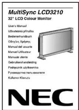
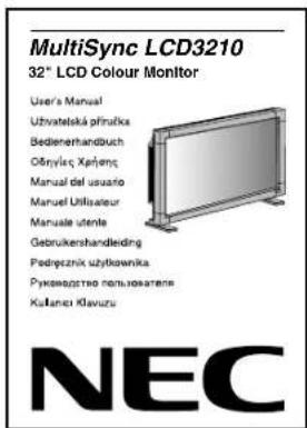
USER MANUAL MultiSync LCD3210 NEC
40" LCD Colour Monitor
User's Manual
natural_image
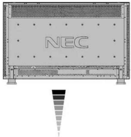
3D rendering of a flat-screen monitor mounted on a base, showing ventilation grilles and mounting feet (no text or symbols)NEC
DECLARATION OF CONFORMITY
This device complies with Part 15 of FCC Rules. Operation is subject to the following two conditions. (1) This device may not cause harmful interference, and (2) this device must accept any interference received, including interference that may cause undesired operation.
U.S. Responsible Party: NEC Display Solutions of America, Inc. Address: 500 Park Boulevard, Suite 1100 Itasca, Illinois 60143
Tel. No.: (630) 467-3000
Type of Product: Computer Monitor
Equipment Classification: Class B Peripheral
Model: MultiSync LCD3210 (L325RM)

We hereby declare that the equipment specified above conforms to the technical standards as specified in the FCC Rules.
Windows is a registered trademark of Microsoft Corporation. NEC is a registered trademark of NEC Corporation. All other brands and product names are trademarks or registered trademarks of their respective owners.
Canadian Department of Communications Compliance Statement
DOC: This Class B digital apparatus meets all requirements of the Canadian Interference-Causing Equipment Regulations.
C-UL: Bears the C-UL Mark and is in compliance with Canadian Safety Regulations according to CAN/CSA C22.2 No. 60950-1.
FCC Information
- Use the attached specified cables with the MultiSync LCD3210 (L325RM) colour monitor so as not to interfere with radio and television reception.
(1) Please use the supplied power cord or equivalent to ensure FCC compliance.
(2) Please use the supplied shielded video signal cable, 15-pin mini D-SUB to 15-pin mini D-SUB.
(3) Please attach the ferrite cores on the Audio Cable. Please see page 11 of this manual.
-
This equipment has been tested and found to comply with the limits for a Class B digital device, pursuant to part 15 of the FCC Rules. These limits are designed to provide reasonable protection against harmful interference in a residential installation. This equipment generates, uses, and can radiate radio frequency energy, and, if not installed and used in accordance with the instructions, may cause harmful interference to radio communications. However, there is no guarantee that interference will not occur in a particular installation. If this equipment does cause harmful interference to radio or television reception, which can be determined by turning the equipment off and on, the user is encouraged to try to correct the interference by one or more of the following measures:
-
Reorient or relocate the receiving antenna.
- Increase the separation between the equipment and receiver.
- Connect the equipment into an outlet on a circuit different from that to which the receiver is connected.
- Consult your dealer or an experienced radio/TV technician for help.
If necessary, the user should contact the dealer or an experienced radio/television technician for additional suggestions. The user may find the following booklet, prepared by the Federal Communications Commission, helpful: "How to Identify and Resolve Radio-TV Interference Problems." This booklet is available from the U.S. Government Printing Office, Washington, D.C., 20402, Stock No. 004-000-00345-4.
bar
| Language | Value | |---|---| | English | 100 | | Česky | 95 | | Deutsch | 90 | | Ελληνικά | 85 | | Español | 80 | | Français | 75 | | Italiano | 70 | | Nederlands | 65 | | Polski | 60 | | Русский | 55 | | Türkçe | 50 |

Index
Important Information .... English-2
Warning, Caution ...... English-2
Declaration .... English-2
Safety Precautions, Maintenance & Recommended Use .... English-3
Contents.... English-4
Parts Name and Functions .... English-5
Control Panel .... English-5
Terminal Panel.... English-6
Wireless Remote Control .... English-7
Operating Range for the Remote Control .... English-7
Handling the remote control .... English-7
Setup Procedure .... English-8
How to Mount and Attach Options to the LCD Monitor .... English-10
Connections ...... English-11
Wiring Diagram.... English-11
Connecting a Personal Computer .... English-12
Connect the LCD Monitor to a Personal Computer .... English-12
Connecting to a Macintosh Computer .... English-13
Connect the LCD Monitor to Macintosh .... English-13
Connecting with Digital Interface Equipment.... English-14
Connect the LCD Monitor to a Computer with a Digital Output .... English-14
Connecting a DVD Player with component out....English-15
Connect the LCD Monitor to a DVD Player .... English-15
Connecting to a Stereo Amplifier.... English-16
Connect the LCD Monitor to a Stereo Amplifier ...... English-16
Basic Operation .... English-16
Power ON and OFF Modes .... English-16
Power Indicator....English-17
Using Power Management .... English-17
Selecting a video source .... English-17
Picture Size .... English-17
Picture Mode .... English-17
Information OSM ...... English-17
OSM (On-Screen-Manager) Controls .... English-18
PICTURE ...... English-18
SCREEN English-19
AUDIO ...... English-20
PICTURE IN PICTURE .... English-21
CONFIGURATION 1 .... English-21
CONFIGURATION 2.... English-22
ADVANCED OPTION .... English-24
Troubleshooting .... English-27
Important Information

WARNING

TO PREVENT FIRE OR SHOCK HAZARDS, DO NOT EXPOSE THIS UNIT TO RAIN OR MOISTURE. ALSO, DO NOT USE THIS UNIT'S POLARIZED PLUG WITH AN EXTENSION CORD RECEPTACLE OR OTHER OUTLETS UNLESS THE PRONGS CAN BE FULLY INSERTED.
REFRAIN FROM OPENING THE CABINET AS THERE ARE HIGH VOLTAGE COMPONENTS INSIDE. REFER SERVICING TO QUALIFIED SERVICE PERSONNEL.

CAUTION

CAUTION: TO REDUCE THE RISK OF ELECTRIC SHOCK, MAKE SURE POWER CORD IS UNPLUGGED FROM WALL SOCKET. TO FULLY DISENGAGE THE POWER TO THE UNIT, PLEASE DISCONNECT THE POWER CORD FROM THE AC OUTLET. DO NOT REMOVE COVER (OR BACK). NO USER SERVICEABLE PARTS INSIDE. REFER SERVICING TO QUALIFIED SERVICE PERSONNEL.

This symbol warns user that uninsulated voltage within the unit may have sufficient magnitude to cause electric shock. Therefore, it is dangerous to make any kind of contact with any part inside this unit.

This symbol alerts the user that important literature concerning the operation and maintenance of this unit has been included. Therefore, it should be read carefully in order to avoid any problems.
Declaration
Declaration of the Manufacturer
We hereby certify that the colour monitor MultiSync LCD3210 (L325RM) is in compliance with
Council Directive 73/23/EEC: -EN 60950-1
Council Directive 89/336/EEC: -EN 55022
- EN 61000-3-2
- EN 61000-3-3
- EN 55024
and marked with

NEC Display Solutions, Ltd.
4-13-23, Shibaura, Minato-Ku
Tokyo 108-0023, Japan
Disposing of your old NEC product

natural_image
Pure electrical circuit lines without any symbolsWithin the European Union
EU-wide legislation, as implemented in each Member State, requires that waste electrical and electronic products carrying the mark (left) must be disposed of separately from normal household waste. This includes monitors and electrical accessories, such as signal cables or power cords. When you need to dispose of your NEC display products, please follow the guidance of your local authority, or ask the shop where you purchased the product, or if applicable, follow any agreements made between yourself and NEC.
The mark on electrical and electronic products only applies to the current European Union Member States.
Outside the European Union
If you wish to dispose of used electrical and electronic products outside the European Union, please contact your local authority so as to comply with the correct disposal method.
Safety Precautions, Maintenance & Recommended Use
FOR OPTIMUM PERFORMANCE, PLEASE NOTE THE FOLLOWING WHEN SETTING UP AND USING THE MULTISYNC LCD3210 LCD COLOUR MONITOR:
- DO NOT OPEN THE MONITOR. There are no user serviceable parts inside and opening or removing covers may expose you to dangerous shock hazards or other risks. Refer all servicing to qualified service personnel.
- Do not spill any liquids into the cabinet or use your monitor near water.
- Do not insert objects of any kind into the cabinet slots, as they may touch dangerous voltage points, which can be harmful or fatal or may cause electric shock, fire or equipment failure.
- Do not place any heavy objects on the power cord. Damage to the cord may cause shock or fire.
- Do not place this product on a sloping or unstable cart, stand or table, as the monitor may fall, causing serious damage to the monitor.
- When operating the MultiSync LCD3210 LCD monitor with its AC 220-240V power supply in Europe, use a power supply cord provided with the monitor.
- In UK, use a BS-approved power cord with molded plug having a black (13A) fuse installed for use with this monitor. If a power cord is not supplied with this monitor, please contact your supplier.
- When operating the MultiSync LCD3210 with a 220-240V AC power source in Australia, use the power cord provided with the monitor. If a power cord is not supplied with this equipment, please contact your supplier.
- For all other cases, use a power cord that matches the AC voltage of the power outlet and has been approved by and complies with the safety standard of your particular country.
- Do not place any objects onto the monitor and do not use the monitor outdoors.
- The inside of the fluorescent tube located within the LCD monitor contains mercury. Please follow the bylaws or rules of your municipality to dispose of the tube properly.
- Do not bend power cord.
- Do not use monitor in very hot, humid, dusty, or oily areas.
- If monitor or glass is broken, do not come in contact with the liquid crystal and handle with care.
- Allow adequate ventilation around the monitor, so that heat can properly dissipate. Do not block ventilated openings or place the monitor near a radiator or other heat sources. Do not put anything on top of the monitor.
- The power cable connector is the primary means of detaching the system from the power supply. The monitor should be installed close to a power outlet, which is easily accessible.
- Handle with care when transporting. Save packaging for transporting.
- Please clean the holes of back cabinet to reject dirt and dust at least once a year because of set reliability.
- If using the cooling fan continuously, it's recommended to wipe holes a minimum of once a month.
Immediately unplug your monitor from the wall outlet and refer servicing to qualified service personnel under the following conditions:
- When the power supply cord or plug is damaged.
- If liquid has been spilled, or objects have fallen into the monitor.
- If the monitor has been exposed to rain or water.
- If the monitor has been dropped or the cabinet damaged.
- If the monitor does not operate normally by following operating instructions.
Recommended Use
- For optimum performance, allow 20 minutes for warm-up.
- Rest your eyes periodically by focusing on an object at least 5 feet away. Blink often.
- Position the monitor at a 90° angle to windows and other light sources to minimize glare and reflections.
- Clean the LCD monitor surface with a lint-free, non-abrasive cloth. Avoid using any cleaning solution or glass cleaner!
- Adjust the monitor's brightness, contrast and sharpness controls to enhance readability.
- Avoid displaying fixed patterns on the monitor for long periods of time to avoid image persistence (after image effects).
- Get regular eye checkups.
Ergonomics
To realize the maximum ergonomic benefits, we recommend the following:
- Use the preset Size and Position controls with standard signals.
- Use the preset Colour Setting.
- Use non-interlaced signals.
- Do not use primary colour blue on a dark background, as it is difficult to see and may produce eye fatigue due to insufficient contrast.
Contents
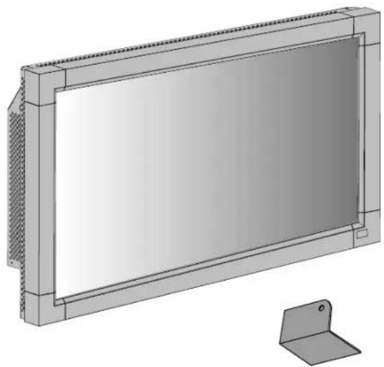
Your new MultiSync LCD3210 monitor box* should contain the following:
- LCD monitor
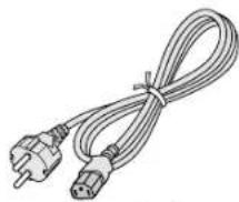
- Power Cord (3m)
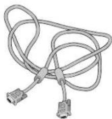
• Video Signal Cable (4m) - User's Manual
• Wireless Remote Control and AA Batteries - Clamper x 3
- Screw (M4 x 8) x 4
- CD-ROM
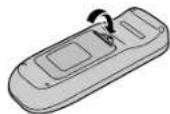
natural_image
3D technical illustration of a rectangular electronic device with a side panel and mounting bracket (no text or symbols)Main switch cover
- Band x 2
- Ferrite Core x 2
- Speaker Plug x 1set (Required for optional Loudspeakers)
- Stand for the Independence x 2
- Thumbscrew for stand (M4 x 27) x 2
- Main switch cover

Stand for the Independence x 2

Thumbscrew for stand x 2
natural_image
Coiled electrical plug and terminal connector (no text or symbols visible)Power Cord
natural_image
Coiled cable with two connectors (no text or symbols visible)Video Signal Cable (D-SUB to D-SUB Cable)
CD-ROM
User's Manual

Screw (M4 x 8) x 4

Clamper x 3


Speaker Plug x 1set (Required for optional Loudspeakers) (Attached on external speaker terminal)
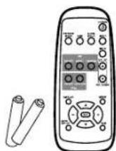
Wireless Remote Control and AA Batteries

Ferrite Core x 2

Band x 2
* Install the stands at the time of unpacking if the display will be used with the stand.
* Remember to save your original box and packing material to transport or ship the monitor.
The following components are prepared as option.
- External Speaker Unit
Parts Name and Functions
Control Panel
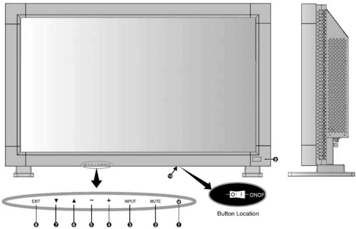
① POWER button (①)
Switches the power on/off. See also page 16.
② MUTE button
Switches the audio mute ON/OFF.
③ INPUT button
Acts as SET button within OSM menu. (Toggle switches between [RGB1], [RGB2], [RGB3], [DVD/HD], [VIDEO] or [VIDEO]). [VIDEO] is enabled by selecting the "SEPARATE" mode in the OSM or by having the "S-VIDEO" cable connected with the "S-VIDEO" signal present and selecting "PRIORITY" MODE. See page 24.
④ PLUS (+) button
Acts as (+) button to increase the adjustment with OSM menu. Increases the audio output level when the OSM menu is turned off.
⑤ MINUS (-) button
Acts as (-) button to decrease the adjustment with OSM menu. Decreases the audio output level when the OSM menu is turned off.
⑥ UP (▲ button
Activates the OSM menu when the OSM menu is turned-off. Acts as ▲ button to move the highlighted area up to select the adjustment with OSM menu.
⑦ DOWN (▼ button
Activates the OSM menu when the OSM menu is turned-off. Acts as ▼button to move the highlighted area down to select the adjustment with OSM menu.
⑧ EXIT button
Activates the OSM menu when the OSM menu is turned-off. Acts as EXIT button to move to previous menu with OSM menu.
⑨ Remote control sensor and Power Indicator
Receives the signal from the remote control (when using the wireless remote control). See also page 7. Glows green when the LCD monitor is in active and glows red when the LCD monitor is in POWER OFF mode. When the LCD monitor is in POWER SAVE mode, it will glow both green and red. When SCHEDULE is enabled, it will blink green and glow red. See page 17. In the case of where a failure is detected, it will blink red.
10 Main Power Switch
On/off Switch to turn main power on/off.
Control Key Lock Mode
This control completely locks out access to all Control Key functions. To activate the control key lock function, press both of “▼” and “▲” and hold down simultaneously for more than 3 seconds. To resume back to user mode, press both of “▼” and “▲” and hold simultaneously for more than 3 seconds.
Terminal Panel
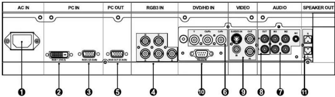
① AC IN connector
Connects with the supplied power cord.
② RGB 1 IN (DVI-D)
To input digital RGB signals from a computer.
* This connector does not support analog input.
③ RGB 2 IN (mini D-Sub 15 pin)
To input analog RGB signals from a personal computer or other RGB equipment.
④ RGB 3 IN [R, G, B, H, V] (BNC)
To input analog RGB signals from a computer or other RGB equipment.
This is also to connect equipment such as a DVD player and HDTV laser disk player. A Sync-on-Green signal can be connected to the G connector.
⑤ RGB OUT (mini D-Sub 15 pin)
To output the signal from RGB 2 or 3.
⑥ DVD/HD IN (BNC)
Connecting equipment such as a DVD player, HDTV device, or Laser disc player.
⑦ AUDIO IN 1, 2, 3
To input audio signal from external equipment such as a computer, VCR or DVD player.
⑧ AUDIO OUT
To output the audio signal from the AUDIO IN 1, 2 and 3 jack.
⑨ VIDEO IN/OUT
VIDEO IN connector (BNC and RCA): To input a composite video signal. BNC and RCA connectors are not available at the same time. (Use only one input).
VIDEO OUT connector (BNC): To output the composite video signal from the VIDEO IN connector.
S-VIDEO IN connector (DIN 4 pin): To input the S-video (Y/C separate signal). See page 24, S-VIDEO MODE SETTING.
⑩ EXTERNAL CONTROL (mini D-Sub 9 pin)
Use when operating the LCD monitor from the RGB equipment like a computer.
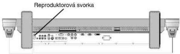
EXTERNAL SPEAKER TERMINAL
To output the audio signal from AUDIO 1, 2 or 3 jack.
Wireless Remote Control
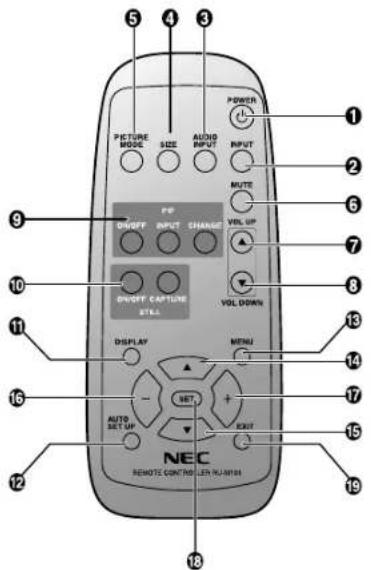
① POWER button
Switches the power on/off.
* If Power Indicator is not glowing, then no controls will work.
② INPUT button
Selects from input signal, [RGB1], [RGB2], [RGB3], [DVD/HD], [VIDEO] and [VIDEO].
[VIDEO] is enabled by selecting the "SEPARATE" mode in the OSM or by having the "S-VIDEO" cable connected with the "S-VIDEO" signal present and selecting "PRIORITY" MODE. See page 24.
③ AUDIO INPUT button
Selects from input audio signal, [AUDIO1], [AUDIO2], [AUDIO3].
4 SIZE button
Selects picture size, [FULL], [NORMAL], [WIDE] and [ZOOM]. See page 17.
⑤ PICTURE MODE button
Selects from picture mode, [HIGHBRIGHT], [STANDARD], [sRGB], [CINEMA]. See page 17.
HIGHBRIGHT: for moving images such as DVD STANDARD: for images (Factory Setting) sRGB: for text based images CINEMA: for movies.
⑥ MUTE button
To switch the mute function on/off.
⑦ VOLUME UP button
Increases the audio output level.
⑧ VOLUME DOWN button
Decreases the audio output level.
⑨ PIP (Picture In Picture) button
ON/OFF button: PIP ON/OFF. See page 21. INPUT button: Selects the "picture in picture" input signal. CHANGE button: Replaces to the main picture and sub picture.
10 STILL button
ON/OFF button: To switch the still picture mode on/off. CAPTURE button: Updates the still picture.
11 DISPLAY button
To switch the information OSM on/off. See page 17.
12 AUTO SETUP button
To enter the auto setup menu. See page 21.
13 MENU button
To switch the menu mode on/off.
14 UP button
Acts as ▲button to move the highlighted area up to select the adjustment with OSM menu. Small screen which adjusted "PIP" mode moves up.
15 DOWN button
Acts as ▼button to move the highlighted area down to select the adjustment with OSM menu. Small screen which adjusted "PIP" mode moves down.
16 MINUS button decrease
Acts as (-) button to decrease the adjustment with OSM menu. Small screen which adjusted "PIP" mode moves left.
17 PLUS button increase
Acts as (+) button to increase the adjustment with OSM menu. Small screen which adjusted "PIP" mode moves right.
18 SET button
Acts as SET button with OSM menu.
19 EXIT button
Turn to previous menu with OSM menu.
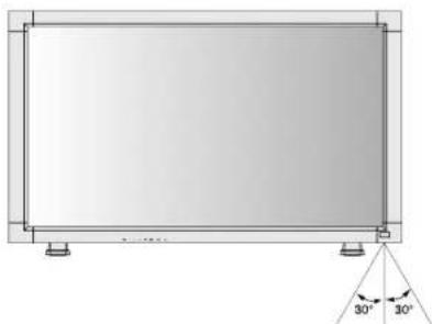
Operating Range for the Remote Control
Point the top of the remote control toward the LCD monitor's remote sensor during button operation.
Use the remote control within a distance of about 7 m/23 ft. from the front of the LCD monitor's remote control sensor and at a horizontal and vertical angle of within 30° within a distance of about 3 m/10 ft.
natural_image
Technical diagram of a rectangular panel with mounting feet and a 30-degree angle indicator (no text or symbols)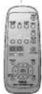
Handling the remote control
* Do not subject to strong shock.
* Do not allow water or other liquid to splash the remote control. If the remote control gets wet, wipe it dry immediately.
* Avoid exposure to heat and steam.
* Other than to install the batteries, do not open the remote control.
Caution: Important, the remote control system may not function when direct sunlight or strong illumination strikes the remote control sensor of the LCD monitor, or when there is an object in the path.
Setup Procedure
1. Determine the installation location
CAUTION: DO NOT ATTEMPT TO INSTALL THE LCD MONITOR BY YOURSELF.
Installing your LCD display must be done by a qualified technician. Contact your dealer for more information.
CAUTION: MOVING OR INSTALLING THE LCD MONITOR MUST BE DONE BY TWO OR MORE PEOPLE.
Failure to follow this caution may result in injury if the LCD monitor falls.
CAUTION: Do not mount or operate the display upside down, face up, or face down.
CAUTION: This LCD has a temperature sensor and cooling fan. If the LCD becomes too hot, the cooling fan will turn on automatically. If the LCD becomes overheated and the cooling fan is running, the "Caution" menu will appear. If the "Caution" menu appears, discontinue use and allow the unit to cool. When the LCD monitor is used in an enclosure or with protection on LCD surface, please check the inside temperature of monitor by "HEAT STATUS" (See page 25). The temperature is too hot than normal condition, please set "cooling fan" to ON on SCREEN SAVER function (See page 22).
IMPORTANT: Lay the protective sheet, which was wrapped around the LCD monitor when it was packaged, beneath the LCD monitor so as not to scratch the panel.
2. Install the remote control batteries
The remote control is powered by 1.5V AA batteries. To install or replace batteries:
- Press and slide to open the cover.
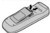
-
Align the batteries according to the (+) and (−) indications inside the case.
-
Replace the cover.
CAUTION: Incorrect use of batteries can result in leaks or bursting.
Be careful especially about the following points.
- Place "AA" size batteries matching the + and - signs on each battery to the + and - signs of the battery compartment.
- Don't mix battery types.
- Don't combine new batteries with used ones. It causes shorter battery life or leakage of batteries.
- Remove dead batteries immediately to prevent battery liquid from leaking into the battery compartment. Don't touch exposed battery acid, it cause damage to your skin.
NOTE: If you do not intend to use the Remote Control for a long period, remove the batteries.
3. Connect external equipment (See pages 11-16)
• To protect the connected equipment, turn off the main power before making connections.
• Refer to your equipment user manual.
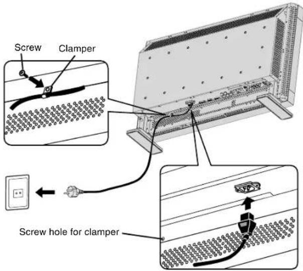
4. Connect the supplied power cord
- The power outlet socket should be installed as near to the equipment as possible, and should be easily accessible.
- Fully insert the prongs into the power outlet socket. Loose connection may cause noise.
- Please fix the power cord by attaching the screw and clamper.
NOTE: Please refer to "Safety Precautions, Maintenance & Recommended Use" section of this manual for proper selection of AC power cord.
5. Switch on the power of all attached external equipment
When connected with a computer, switch on the power of the computer first.
6. Operate the attached external equipment
Display the signal on the external equipment you wish.
7. Adjust the sound
Make adjustments when adjustment of the volume is required.
8. Adjust the screen (See pages 18-25)
Make adjustments when adjustment of the screen display position or distortion is required.
9. Adjust the image (See pages 18-25)
Make adjustments when picture adjustment such as the brightness or contrast is required.
10. Recommended Adjustment
To reduce the risk of "image persistence", please adjust the following items based on the application being used.
"SCREEN SAVER" (See page 22), "SIDE BORDER COLOR" (See page 22), "DATE & TIME" (See page 25), "SCHEDULE" (See page 25).
11. When the monitor is installed in the portrait position
- Remove the stands (feet).
- Left edge should be the upper edge from front view.
12. Installing and removing stand
How to install stand
- Please turn monitor off.
- Place stand onto monitor with the long ends of the feet in front of the monitor.
- After inserting stand in guide block, fasten thumbscrews on both sides of the monitor.
How to remove the stand
- Spread the protective sheet on the flat surface, such as a desk.
- Place monitor on the protective sheet.
- Remove thumbscrews with a screwdriver or with your fingers and place them in a safe place for reuse.
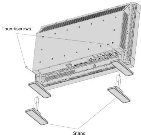
NOTE: Place stand onto monitor so that the long end of the feet are in the front.
CAUTION: Handle with care when mounting the display stand and avoid pinching your fingers.
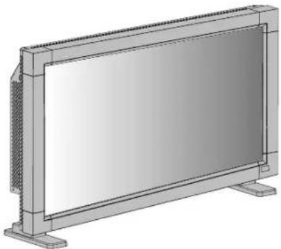
13. When using external speakers
We recommend to using the option speakers designed for the MultiSync LCD3210.
The external speaker terminals of the MultiSync LCD3210 may be connectable with the speaker plug of a mainframe sound speaker.
It this case, please exchange the lead connector of a mainframe sound speaker for an attached speaker plug.
natural_image
Exterior view of a rectangular concrete slab with side supports and textured corners (no text or symbols)English

How to use the attached speaker plug
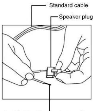
Insert the negative (-) side of a standard speaker cable into the negative (-) side of the speaker plug. The negative side of a standard speaker cable has a stripe running the length of the cable. Insert remaining wire into the positive (+) side of the speaker plug. Hold down on the small lever on the speaker plug to insert cable.
natural_image
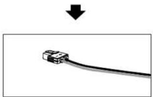
Simple line drawing of a cable with a connector, no text or symbols presentFixed cable and speaker plug.
natural_image
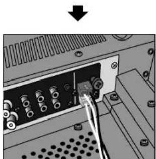
Close-up of an electronic device showing a cable inserted into a port with connectors (no visible text or symbols)Insert the fixed cable and speaker plug to the speaker terminal.
How to Mount and Attach Options to the LCD Monitor
You can attach mounting accessories to the LCD monitor in one of the following two ways:
1. In the upright position
natural_image
3D rendering of a rectangular electronic device with ventilation grilles and mounting base (no text or symbols)2. Lay the screen face down
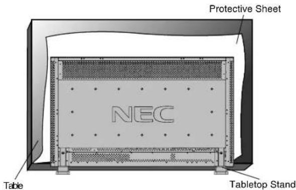
Lay the protective sheet on a table, which was wrapped around the monitor when it was packaged, beneath the screen surface so as not to scratch the screen face.
This device cannot be used or installed without the Tabletop Stand or other mounting accessory. Failure to follow correct mounting procedures could result in damage to the equipment or injury to the user or installer. Product warranty does not cover damage caused by improper installation. Failure to follow these recommendations could result in voiding your warranty.
When using with other mounting accessory, it must be a VESA-compatible mounting method and the screws must be M6 of size and 10mm or longer of length under consideration of the thickness of the mounting method. (Recommended torque: 470 - 550N·cm). NEC recommends using mounting interface that comply with TÜV-GS and/or UL1678 standard in North America.
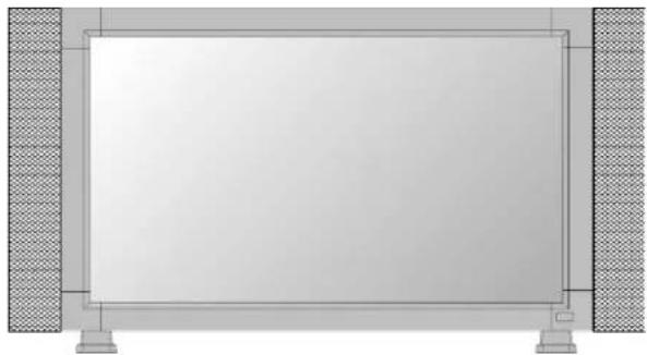
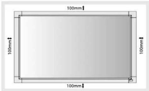
3. Ventilation Requirements for enclosure mounting
To allow heat to disperse, leave space between surrounding objects as shown in the diagram below.
4. To avoid falling down
Fasten the LCD monitor to wall using a cord or chain, which is sufficient to support the weight of the LCD monitor (approx. 16.4kg).
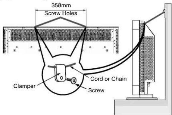
Before moving the LCD monitor, the cord or chain should be removed.
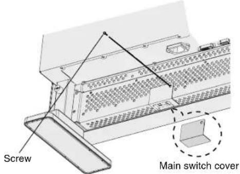
5. To prevent the main power switch from being changed
To prevent the ability to use the main power switch, please attach the main switch, which is enclosed as an accessory.
NOTE: With the main power switch cover in place, the main power switch cannot be turned off. Remove main power switch cover in order to switch off the display.
English-10
Connections
Before making connections:
* First turn off the power of all the attached equipment and make connections.
* Refer to the user manual included with each separate piece of equipment.
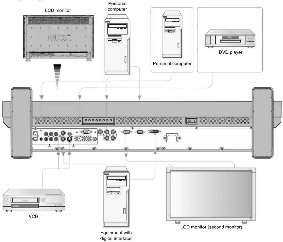
Wiring Diagram
flowchart
graph TD
    A["LCD monitor"] --> B["Personal computer"]
    B --> C["DVD player"]
    D["VCR"] --> E["Equipment with digital interface"]
    F["LCD monitor (second monitor)"] --> G["Equipment with digital interface"]
    H["NEC"] --> I["Device with ports"]
    J["Other devices"] --> K["Device with ports"]
| Attaching the Ferrite CoreAttach the Ferrite Core to PC Audio Cable.Use of the cable without mounting the ferrite core will result in the occurrence of noise. | Mounting Position of Ferrite Core |
For PC Audio Cable1 Open the ferrite core and clamp it on the PC Audio cable.Ferrite Cori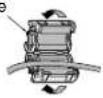  | 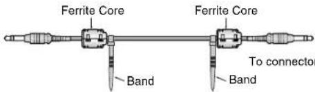 of PCTo AUDIO 1 of monitor of PCTo AUDIO 1 of monitor |
English-11
Connecting a Personal Computer
Connecting your computer to your LCD monitor will enable you to display your computer's screen image.
Some video cards may not display an image correctly.
| Resolution | Scanning frequency | Remarks | |
| Horizontal Vertical | |||
| 640 x 480 31 | 5Hz 60Hz | ||
| 800 x 600 37 | 9Hz 60Hz | ||
| 1024 x 768 48 | 4Hz 60Hz | ||
| 1280 x 768 48 | Hz 60Hz | ||
| 1360 x 768 48 | Hz 60Hz Recommended resolution | ||
| 1280 x 1024 64 | Hz 60Hz Compressed image | ||
| 1600 x 1200 75 | Hz 60Hz Compressed image | ||
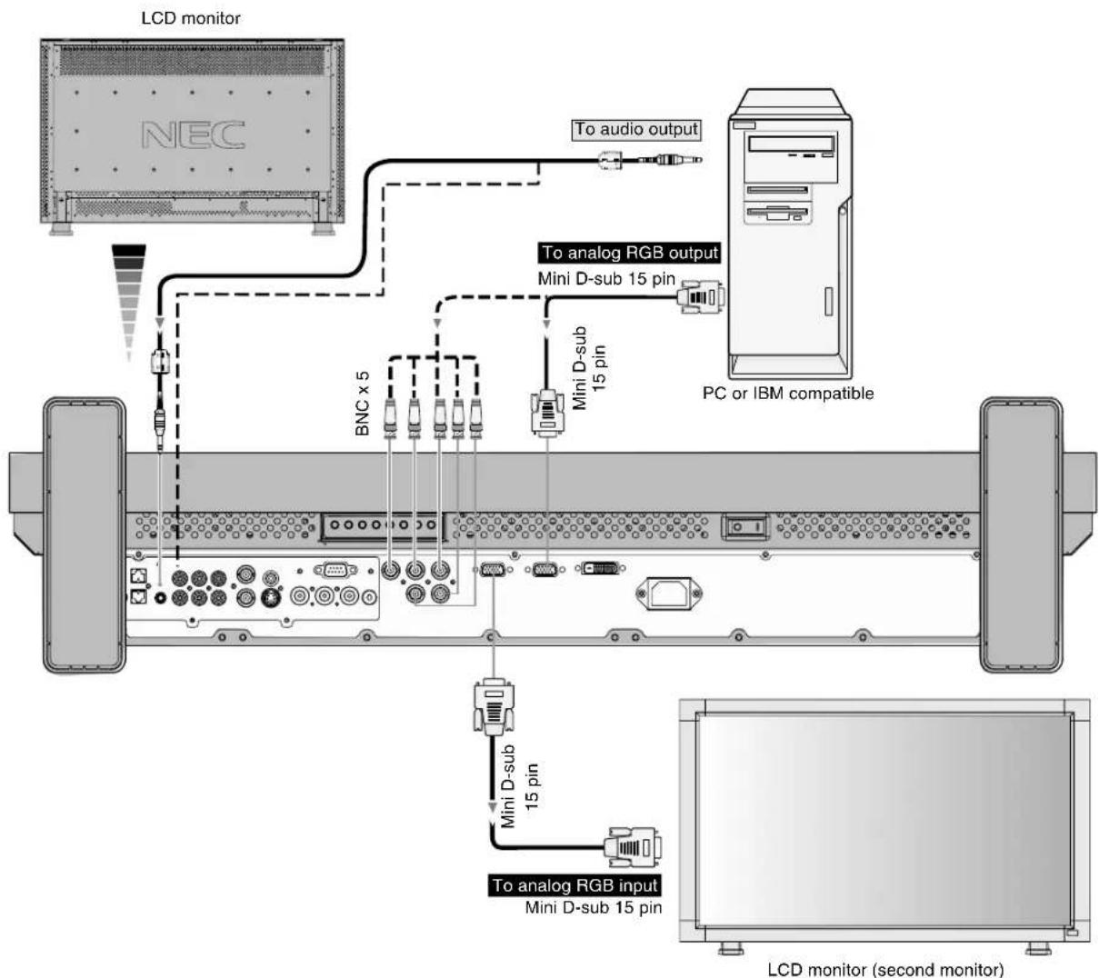
Connect the LCD Monitor to a Personal Computer
- To connect the RGB 2 IN connector (mini D-sub 15 pin) on the LCD monitor, use the supplied PC - Video RGB signal cable (mini D-sub 15 pin to mini D-sub 15 pin).
- To connect the RGB 3 connector (BNC) on the LCD monitor, use a signal cable which is available separately (mini D-sub 15 pin to BNC x 5). Select RGB 3 from the INPUT button.
- When connecting one or more LCD monitors, use the RGB OUT connector (mini D-sub 15 pin).
• The AUDIO IN 1, 2 and 3 can be used for audio input. For connection, select AUDIO 1, 2 or 3 from the AUDIO INPUT button.
flowchart
graph TD
    A["LCD monitor"] --> B["NEC"]
    B --> C["To audio output"]
    C --> D["PC or IBM compatible"]
    D --> E["Mini D-sub 15 pin"]
    E --> F["To analog RGB output"]
    F --> G["BNC x 5"]
    G --> H["Mini D-sub 15 pin"]
    H --> I["To analog RGB input"]
    I --> J["Mini D-sub 15 pin"]
    J --> K["LCD monitor (second monitor)"]
English-12
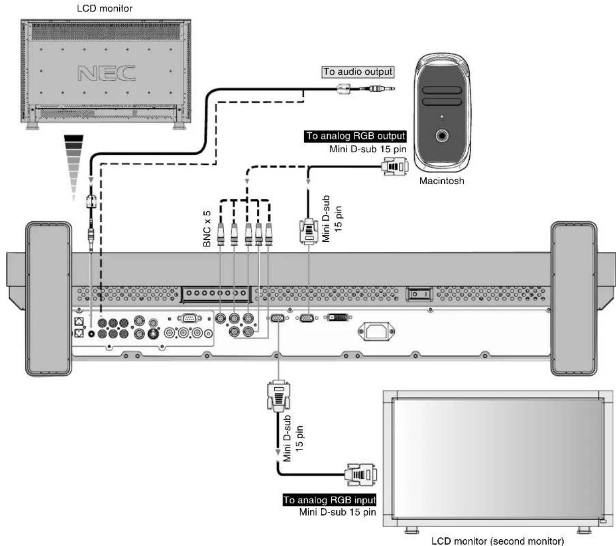
Connecting to a Macintosh Computer
Connecting your Macintosh computer to your LCD monitor will enable you to display your computer's screen image. Some video cards or drivers may not display images correctly.
Connect the LCD Monitor to Macintosh
- To connect the RGB 2 IN connector (mini D-sub 15 pin) on the LCD monitor, use the supplied PC - Video RGB signal cable (mini D-sub 15 pin to mini D-sub 15 pin).
- To connect the RGB 3 IN connector (BNC) on the LCD monitor, use the signal cable available separately (mini D-sub 15 pin to BNC x 5).
- Refer to your Macintosh's owner's manual for more information about your computer's video output requirements and any special identification or configuring your monitor's image and monitor may require.
• The AUDIO IN 1, 2 and 3 can be used for audio input. For connection, select AUDIO 1, 2 or 3 from the AUDIO INPUT button.
flowchart
graph TD
    A["LCD monitor"] --> B["NEC"]
    B --> C["To audio output"]
    C --> D["Macintosh"]
    D --> E["Mini D-sub 15 pin"]
    E --> F["To analog RGB output"]
    F --> G["BNC x 5"]
    G --> H["Mini D-sub 15 pin"]
    H --> I["To analog RGB input Mini D-sub 15 pin"]
    I --> J["LCD monitor (second monitor)"]
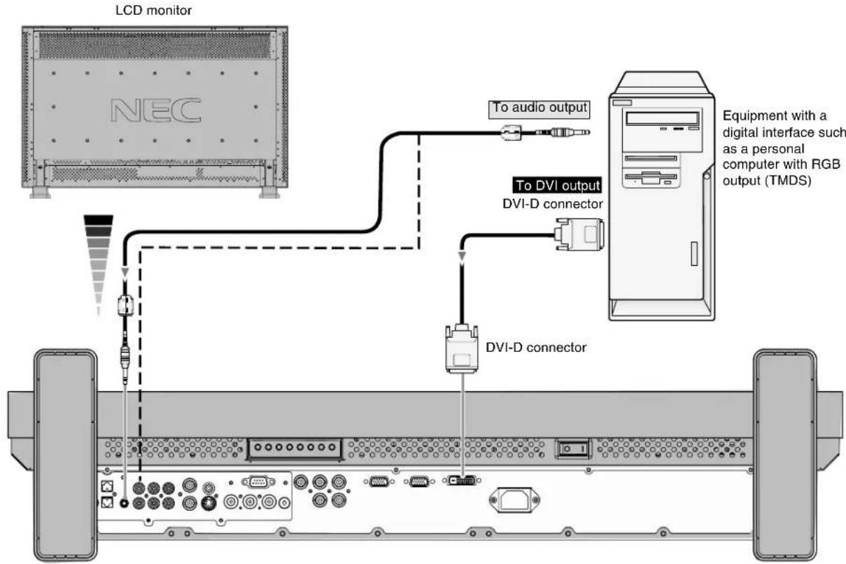
Connecting with Digital Interface Equipment
Connections can be made with equipment that is equipped with a digital interface compliant with the DVI (Digital Visual Interface) standard.
Connect the LCD Monitor to a Computer with a Digital Output
- The RGB 1 IN connector also accepts a DVI-D cable.
- Input TMDS signals conforming to DVI standards.
- To maintain display quality, use a cable with a quality prescribed by DVI standards.
• The AUDIO IN 1, 2 and 3 can be used for audio input. For connection, select AUDIO 1, 2 or 3 from the AUDIO INPUT button.
flowchart
graph TD
    A["LCD monitor"] -->|To audio output| B["NEC"]
    A -->|To DVI output| C["DVI-D connector"]
    C --> D["DVI-D connector"]
    D --> E["Equipment with a digital interface such as a personal computer with RGB output (TMDS)"]
    style A fill:#f9f,stroke:#333
    style B fill:#ccf,stroke:#333
    style C fill:#cfc,stroke:#333
    style D fill:#fcc,stroke:#333
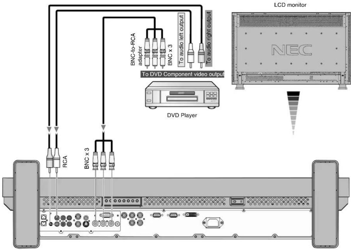
Connecting a DVD Player with component out
Connecting your DVD player to your LCD monitor will enable you to display DVD video.
Refer to your DVD player user's manual for more information.
Connect the LCD Monitor to a DVD Player
- To connect the DVD/HD IN connector (BNC) on the LCD monitor, use a separately available BNC connector cable. You will need a BNC-to-RCA adapter to connect a DVD player with an RCA pin jack to the BNC connector cable (not provided). The AUDIO IN 2 and 3 (both RCA) can be used for audio input. For connection, select [AUDIO 2] or [AUDIO 3] from the AUDIO INPUT button.
flowchart
graph TD
    A["RAM"] -->|RCA| B["Residential Display"]
    A -->|BNC x 3| C["Residential Display"]
    C --> D["DVD Player"]
    D --> E["To DVD Component video output"]
    E --> F["BNC to-RCA adapter"]
    E --> G["BNC x 3"]
    E --> H["To audio left output"]
    E --> I["To audio right output"]
    J["LCD monitor"] --> K["NEC"]
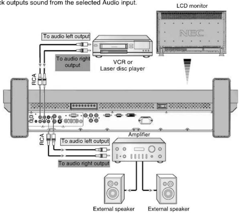
Connecting to a Stereo Amplifier
You can connect your stereo amplifier to your LCD monitor. Refer to your amplifier owner's manual for more information.
Connect the LCD Monitor to a Stereo Amplifier
- Turn on the LCD monitor and the amplifier only after all connections have been made.
• Use an RCA cable to connect the AUDIO OUT connector (RCA) on the LCD monitor and the audio input on the amplifier. - Do not reverse the audio left and right jacks.
• The AUDIO IN is used for audio input.
• The AUDIO OUT jack outputs sound from the selected Audio input.
flowchart
graph TD
    A["External speaker"] --> B["Amplifier"]
    C["LCD monitor"] --> D["VCR or Laser disc player"]
    D --> E["To audio right output"]
    D --> F["To audio left output"]
    D --> G["To audio right output"]
    H["RCA"] --> I["To audio left output"]
    H --> J["To audio right output"]
    K["External speaker"] --> L["Amplifier"]
    M["LCD monitor"] --> N["To audio right output"]
    M --> O["To audio left output"]
Basic Operation
Power ON and OFF Modes
The LCD monitor power indicator will turn green while powered on, or red when in off mode. The monitor can be powered on or off using the following three options:
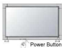
1. Pressing the power button.
Note: Before pressing the power button, be sure to turn on the Main Power Switch on the LCD monitor.
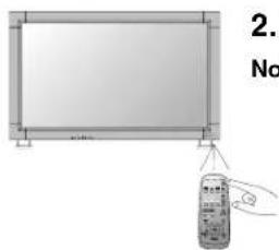
2. Using the remote control.
Note: Before operating the remote control, be sure to turn on the Main Power Switch on the LCD monitor.
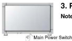
3. Pressing the Main Power Switch.
Note: When the Main Power Switch is used to power off the LCD, the remote control and the power button will not activate the on mode and both green and red power indicator turn off. Be sure to turn the Main Power Switch to the on mode before using these two options.
Power Indicator
| Status | |
| Power ON Green | |
| Power OFF Red | |
| Power Standby when Red On “SCHEDULE” is enable Green Blinking | |
| Power Standby Red, Green | |
| Diagnosis (Detecting failure) Red Blinking* See troubleshooting on page 27 | |
Using Power Management
The LCD monitor follows the VESA approved DPM Power Management function.
The power management function is an energy saving function that automatically reduces the power consumption of the display when the keyboard or the mouse has not been used for a fixed period.
The power management feature on your new display has been set to the "ON" mode. This allows your display to enter a Power Saving Mode when no signal is applied. This could potentially increase the life and decrease the power consumption of the display.
Selecting a video source
To view a video source:
Use the input button to set [VIDEO].
Use the COLOR SYSTEM menu to set [AUTO], [NTSC], [PAL], [SECAM], [PAL60], [4.43NTSC], according to your video format.
Picture Size
RGB 1, 2, 3 FULL ZOOM NORMAL →
DVD/HD, VIDEO FULL WIDE ZOOM-NORMAL →
| Signal Type | NORMAL SIZE | Recommended Size |
| 4:3 | 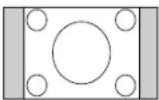 | NORMAL |
ZOOM(DYNAMIC)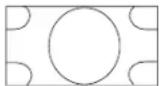 | ||
| Squeeze | 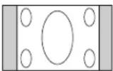 | FULL |
| Letter box | 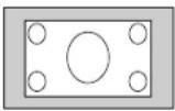 | WIDE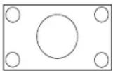 |
NORMAL: Display by the inputed signal aspect ratio by PC signal, or display in 4:3 aspect ratio at DVD/HD or VIDEO signal.
FULL: Display in entire screen.
WIDE: Expand 16:9 letter box signal to entire screen.
ZOOM (DYNAMIC): Expand 4:3 pictures to the entire screen with non-linearity. (Some around image will be cut by expansion.)
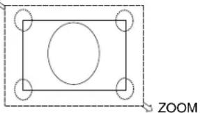
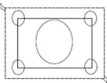
ZOOM
Image can be expanded beyond the active display area. The image which is outside of active display area is not displayed.
ZOOM
natural_image
Simple geometric diagram with a rectangle, circle, and corner markers (no text or symbols)Picture Mode
RGB 1, 2, 3 HIGHBRIGHT→STANDARD→sRGB
DVD/HD, VIDEO HIGHBRIGHT→STANDARD→CINEMA
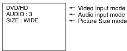
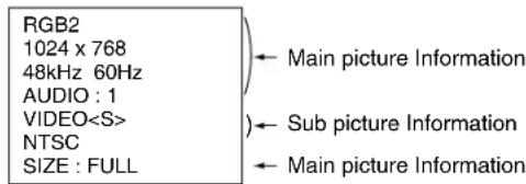
Information OSM
RGB1, 2, 3
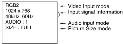
DVD/HD
VIDEO

PIP
Main:RGB2
Sub:VIDEO
English-17
OSM (On-Screen-Manager) Controls
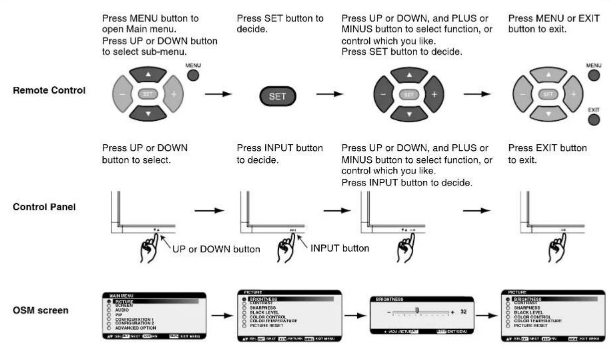
flowchart
graph TD
    A["Remote Control"] --> B["Press MENU button to open Main menu. Press UP or DOWN button to select sub-menu."]
    B --> C["Press SET button to decide."]
    C --> D["Press UP or DOWN, and PLUS or MINUS button to select function, or control which you like. Press SET button to decide."]
    D --> E["Press MENU or EXIT button to exit."]
    F["Control Panel"] --> G["UP or DOWN button"]
    G --> H["INPUT button"]
    H --> I["Press INPUT button to decide."]
    I --> J["Press EXIT button to exit."]
    K["OSM screen"] --> L["MAIN MENU: 🎨️ 🎩️ 🎩️ 🎩️ 🎩️ 🎩️ 🎩️ 🎩️ 🎩️ 🎩️ 🎩️ 🎩️ 🎩️ 🎩️ 🎩️ 🎩️ 🎩️ 🎩️ 🎩️ 🎩️ 🎩️ 🎩️ 🎩️ 🎩️ 🎩️ 🎩️ 🎯️"]
| Main-MenuPICTURE | 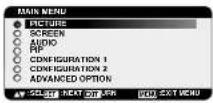 | ||
| Sub-Menu | |||
| BRIGHTNESS | 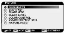 | 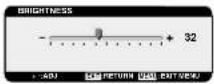 | Adjusts the overall image and background screen brightness.Press + button to increase brightness.Press - button to decrease brightness. |
| CONTRAST | 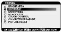 | 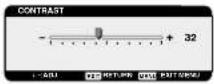 | Adjusts the image contrast in relation to the input signal.Press + button to increase contrast.Press - button to decrease contrast.NOTE: sRGB picture mode is standard and cannot be changed. |
| SHARPNESS | 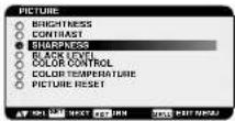 | 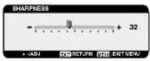 | This function is digitally capable to keep crisp image at any timing. It is adjustable to get a distinct image or a soft one as you prefer and set independently for each picture mode.Press + button to increase sharpness.Press - button to decrease sharpness. |
| BLACK LEVEL | 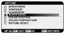 | 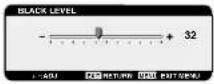 | Adjusts the image brightness in relation to the background.Press + button to increase black level.Press - button to decrease black level.NOTE: sRGB picture mode is standard and cannot be changed. |
| NOISE REDUCTION*:INPUT DVD/HD, VIDEO only | 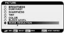 | 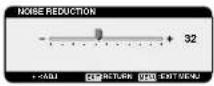 | Adjusts the noise reduction level.Press + button to increase reduction level.Press - button to decrease reduction level. |
| TINT*:INPUT DVD/HD,VIDEO only | 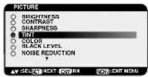 | 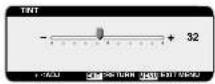 | Adjust the tint of the screen.Press + button to Skin colour becomes greenish.Press - button to Skin colour becomes purplish. |
| COLOR*:INPUT DVD/HD,VIDEO only | 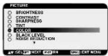 | 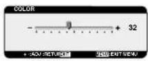 | Adjust the colour depth of the screen.Press + button to increase colour depth.Press - button to decrease colour depth. |
| COLOR CONTROL*:INPUT RGB1,2,3 only | 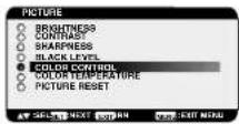 | 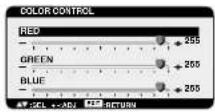 | R, G, B: Increases or decreases Red, Green and Blue, depending upon which is selected. The change in colour will appear on screen and the direction (increase or decrease) will be shown by the colour bars.NOTE: sRGB picture mode is standard and cannot be changed. |
| COLOR TEMPERATURE | 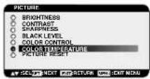 |  | To adjust the colour temperature of entire screen.Adjusting lower colour temperature makes the screen reddish and higher colour temperature makes the screen bluish.NOTE: sRGB picture mode is standard and cannot be changed. |
| PICTURE RESET | 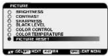 | 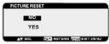 | Selecting Picture reset allows you to reset all OSM settings about PICTURE setting.Select "Yes" and press "SET" button to restore to factory preset data.Press "EXIT" button to cancel and then return to the previous menu. |
| Main-MenuSCREEN | 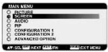 | ||
| Sub-Menu | |||
| H POSITION | 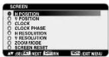 | 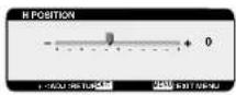 | Controls Horizontal Image position within the display area of the LCD.Press + button to move screen to right.Press - button to move screen to left. |
| V POSITION | 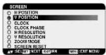 | 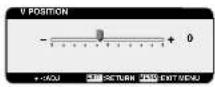 | Controls Vertical Image position within the display area of the LCD.Press + button to move screen to UP.Press - button to move screen to DOWN. |
| CLOCK*:INPUT RGB2/3 only | 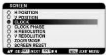 | 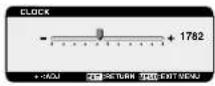 | Press + button to expand the width of the image on the screen to the right.Press - button to narrow the width of the image on the screen to the left. |
| CLOCK PHASE*:INPUT RGB2/3, DVD/HD only | 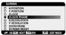 | 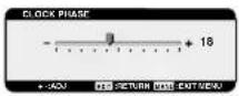 | To change the snow noise of the image. |
| H RESOLUTION*:INPUT RGB1/2/3 only | 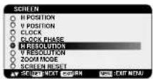 | 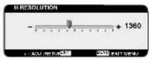 | Adjusts the horizontal size by increasing or decreasing the setting.Press + button to expand the width of the image on the screen.Press - button to narrow the width of the image on the screen. |
| V RESOLUTION*:INPUT RGB1/2/3 only | 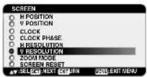 | 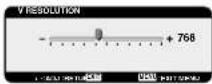 | Adjusts the vertical size by increasing or decreasing the setting.Press + button to expand the height of the image on the screen.Press - button to narrow the height of the image on the screen. |
| ZOOM MODE | 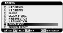 | 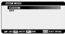 *:INPUT RGB1/2/3 only *:INPUT RGB1/2/3 only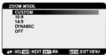 *:INPUT DVD/HD,VIDEO only *:INPUT DVD/HD,VIDEO only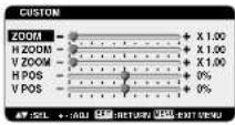 | Selects the screen zoom mode. Zoom mode will be selected when you select the “ZOOM” by pushing the “SIZE” button on remote controller.When you select the “CUSTOM”, you will be able to adjust optional horizontal and vertical size.You can also select 16:9, 14:9 and DYNAMIC.(INPUT DVD/HD,VIDEO only)Press “SET” button to show a control menu as follows:Increase or decrease “ZOOM” slider to adjust the whole size and then adjust horizontal and vertical size by H ZOOM and V ZOOM. Increase or decrease “H POS” and “V POS” to adjust the picture position.Selecting “DYNAMIC” will expand 4:3 pictures to the entire screen with non-linearity. (Some around image will be cut by expansion.) Dynamic image is the same as FULL size image when HDTV 1080i or 720p signal is input.Selecting “OFF” image will be displayed 1 by 1 pixel. (If you input over 1366x768 resolution signal, it will be displayed as shrank image.) |
| SCREEN RESET | 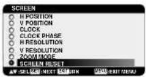 | 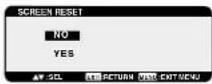 | Selecting Screen reset allows you to reset all OSM settings from SCREEN setting.Select “Yes” and press “SET” button to restore the factory preset data.Press “EXIT” button to cancel and then return to the previous menu. |
Main-MenuAUDIO 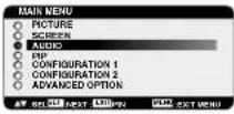 | |||
| Sub-Menu | |||
| BALANCE | 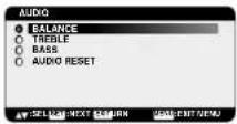 | 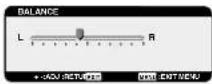 | Adjust the balance of L/R volume.Press + button to move the stereo sound image to right.Sound of the left side will be small.Press - button to move the stereo sound image to left. |
| TREBLE | 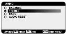 | 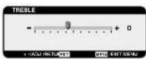 | To accentuate or reduce the high frequency sound.Press + button to increase TREBLE sound.Press - button to decrease TREBLE sound. |
| BASS | 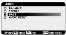 | 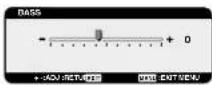 | To accentuate or reduce the low frequency sound.Press + button to increase BASS sound.Press - button to decrease BASS sound. |
| AUDIO RESET | 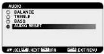 | 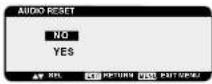 | Selecting Audio reset allows you to reset all OSM settings from AUDIO setting.Select "Yes" and press "SET" button to restore the factory preset.Press "EXIT" button to cancel and then return to the previous menu. |
English-20
| Main-MenuPICTURE IN PICTURE | 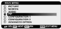 | |
| Sub-Menu | ||
| PIP SIZE | Selecting the size of picture inserted at the “Picture-in-Picture” (PIP) mode.“Large”, “Middle” and “Small” are available. | |
| PIP AUDIO | Selecting the sound source in PIP mode.When selecting “MAIN AUDIO”, you will get the sound for the main picture and when selecting “PIP AUDIO”, you will get the sound for the picture instead. | |
| PIP RESET | Selecting PIP Reset allows you to reset all OSM settings from PIP setting.Select “Yes” and press “SET” button to restore the factory preset data.Press “EXIT” button to cancel and then return to the previous menu. | |
| Main-MenuCONFIGURATION 1 | 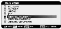 | ||
| Sub-Menu | |||
| AUTO SETUP*:INPUT RGB2/3 only | Press “SET” button to automatically adjust screen size, horizontal position, vertical position, clock, clock phase, white level and black level.Press “EXIT” button to cancel execution AUTO SETUP and then will return to the previous menu. | ||
| AUTO ADJUST*:INPUT RGB2/3 only | Selecting the auto adjust ON/OFF.Selecting ON when changing the timing, the horizontal position, vertical position and clock-phase will adjust automatically according to input signal. | ||
| AUTO BRIGHTNESS*:INPUT RGB1/2/3 only | Selecting the auto brightness ON/OFF.When select “ON”, the brightness will be automatically adjusted. | ||
| POWER SAVE | Selecting RGB “ON”, the monitor will go to power management mode when RGB1,2,3 sync is lost.Selecting VIDEO “ON”, the monitor will go to power management mode after about 10 minutes delay from when DVD/HD and VIDEO input signal is lost. | ||
| LANGUAGE | OSM control menus are available in seven languages. | ||
| SCREEN SAVER | 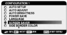 | 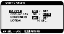 | Select “SCREEN SAVER” functions to reduce the risk of the “image persistence”.GAMMA: The display gamma is changed and fixed when selected “ON”.COOLING FAN: The built in cooling fan is always on when set “ON”.BRIGHTNESS: The brightness is decreased when selected “ON”.MOTION: Image is slightly expanded and moves 4 directions (UP, DOWN, RIGHT, LEFT) periodically (Need setting the time for movement).Movement area is approximately +/- 10mm from original position; Please locate the important information such as text within 90% area of screen image.See note (1) for this functions.PIP and STILL will be disabled when “MOTION” is active. |
| COLOR SYSTEM*:INPUT VIDEO only | 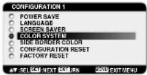 | 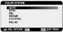 | Selecting the Colour System depends on your input video format.AUTO: NTSC, PAL, SECAM, PAL60 or 4.43 NTSC is automatically selected.NTSC: Specific selection of NTSC.PAL: Specific selection of PAL.SECAM: Specific selection of SECAM.PAL-60: Specific selection of PAL60.4.43NTSC: Specific selection of 4.43 NTSC. |
| SIDE BORDER COLOR | 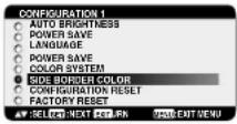 | 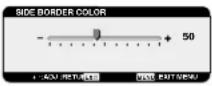 | Adjustment the side black bar color white when 4:3 image displayed, black to white.Press + button, the bar will become whiter.Press - button, the bar will become darker. |
| CONFIGURATION RESET | 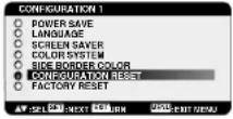 | 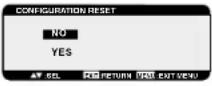 | Selecting the CONFIGURATION RESET allows you to reset all configuration settings.Select “Yes” and press “SET” button to restore the factory preset data.Press “EXIT” button to cancel and return the previous menu. |
| FACTORY RESET | 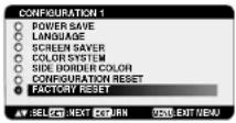 | 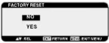 | Selecting “YES” allows you to reset PICTURE, SCREEN, AUDIO, CONFIGURATION1,2 and ADVANCED OPTION will be back to factory settings (except LANGUAGE, DATE & TIME and SCHEDULE).Select “YES” and press “SET” button to restore the factory preset data.Press “EXIT” button to cancel and return the previous menu. |
| Main-MenuCONFIGURATION 2 | 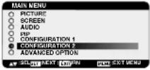 | |
| Sub-Menu | ||
| LONG CABLE MANUAL*:INPUT RGB2/3 only | To compensate for image degradation, which is caused by using a long cable.VIDEO EQTo optimize the shape (Tailing) of RED, GREEN and BLUE signal.Level: 0 - 7SYNC TERMINATE (Input RGB 3 only)To select the terminate resistance for matching the cable impedance.HI: 2.2K ohm/LO:75 ohm | |
English-22
| OSM TURN OFF | 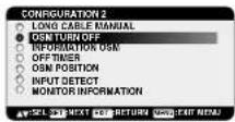 |  | The OSM control menu will stay on as long as it is use.In the OSM Turn Off submenu, you can select how long the monitor waits after the last touch of a button to shut off the OSM control menu. The preset choices are 10 -240 seconds. |
| INFORMATION OSM | 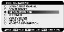 | 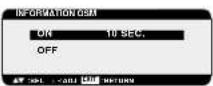 | Selects the information OSM display or not. The information OSM will display when input signal or source change or warning message like as no-signal or out-of range.A time between 3 to 10 seconds is available. |
| OFF TIMER | 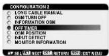 | 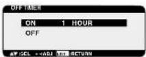 | To select OFF TIMER mode ON/OFF.In the OFF TIMER menu, you can preset the monitor to automatically power down.A time between 1 to 24 hours is available.When the OFF TIMER is set, the SCHEDULE (see page 25) settings will be disabled. |
| OSM POSITION | 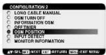 | 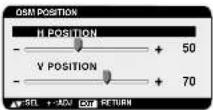 | Adjusts the position of the OSM menu. |
| INPUT DETECT | 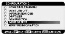 | 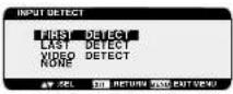 | Selects the method of input detection when more than two computers are connected.FIRST DETECT: When the current video input signal is not present, then the monitor searches for a video signal from the other video input port. If the video signal is present in the other port, then the monitor switches the video source input port to the new found video source automatically. The monitor will not look for other video signals while the current video source is present.This function is available at input RGB 1/2/3.LAST DETECT: When the monitor is displaying a signal from the current source and a new secondary source is supplied to the monitor, the monitor will automatically switch to the new video source. When current video input signal is not present, the monitor searches for a video signal from the other video input port. If the video signal is present in the other port, then the monitor switches the video source input port to the new found video source automatically.This function is available at input RGB 1/2/3.VIDEO DETECT: DVD/HD or VIDEO inputs will have priority over RGB1/2/3. When DVD/HD or VIDEO input signal is present the monitor will change and keep to the DVD/DH or VIDEO input.NONE: The Monitor will not search the other video input port. |
| MONITOR INFORMATION | 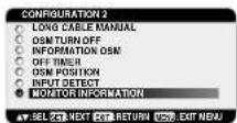 | 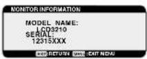 | Indicates the model and serial number of your monitor. |
| Main-MenuADVANCED OPTION | 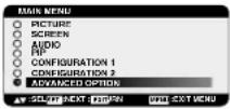 | ||
| Sub-Menu | |||
| S-VIDEO MODE |  | 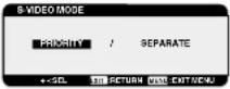 | Selects the S-Video input port function.PRIORITY:If cable is connected to the S-Video input, it will have priority the composite input port.SEPARATE:S-Video port and Composite port are selectable as independent input port. |
| INPUT RESOLUTION*:INPUT RGB2/3 only | 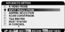 | 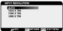 | Selects to decision of input signal about below timings, 1024x768, 1280x768 and 1360x768.AUTO: Determines the resolution automatically.1024x768: Determines the resolution as 1024x7681280x768: Determines the resolution as 1280x7681360x768: Determines the resolution as 1360x768 |
| BLACK LEVEL EXPANSION*:INPUT VIDEO, DVD/HD only | 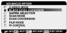 | 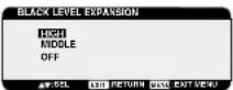 | Selects a level of black expansion.In case of go under the black cut-off level, please adjust the "Black level" in moderation on OSM menu. |
| GAMMA SELECTION | 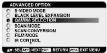 | 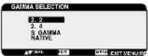 | Selects a display gamma.1: 2.22: 2.43: S gamma4: NativeNOTE: sRGB picture mode is standard and cannot be changed. |
| SCAN MODE*:INPUT DVD/HD, VIDEO only | 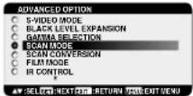 | 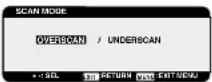 | Changes the display area of the image.OVERSCAN: Set to display area about 95%UNDERSCAN: Set to display area about 100% |
| SCAN CONVERSION | 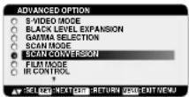 |  | Selects IP (Interlace to Progressive) converter function.PROGRESSIVE: Enable the IP function, to convert interlace signal to progressive. Normally use this setting.INTERLACE: Disable the IP function.NOTE: This mode is better suited for motional pictures, but it is in danger of image retention. |
| FILM MODE*:INPUT DVD/HD, VIDEO only | 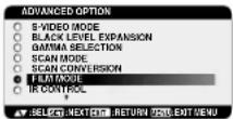 | 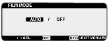 | Selects Film mode function.AUTO: Enable the Film mode function. This mode is better suited for movies, which is converted 24 Frames/sec source to DVD Video. We recommend to select "PROGRESSIVE" in "SCAN CONVERSION".OFF: Disable the Film mode function. This mode is better suited for Broadcasting or VCR source. |
| IR CONTROL | 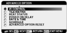 | 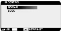 | Selects the infrared wireless remote controller mode.The item in this menu will become effective by pressing "SET" button on the selected item.NORMAL: The monitor will be controlled normally by wireless remote controller.LOCK: Disable the monitor control by infrared wireless remote controller.Keep pressing "DISPLAY" button during 5 sec or more, this setting will return to "NORMAL". |
| TILE MATRIX | 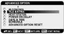 | 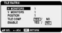 | Tile Matrix demonstrates multiple screens. This feature provides a single large screen using up to 16 monitors. It will be able to divide up to 4 each H and V.This requires you to feed the PC output into each of the monitors through a distributor.H MONITORS: Select number of horizontal divide.V MONITORS: Select number of vertical divide.POSITION: Select a position to expand the screen.TILE COMP: Works in tandem with Tile Matrix to compensate for the width of the tile bezels in order to accurately display the image.ENABLE: Select "YES", the monitor will expand the selected position.PIP and STILL and "DYNAMIC" ZOOM mode will be disabled when "TILE MATRIX" is activated. |
| HEAT STATUS | 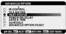 | 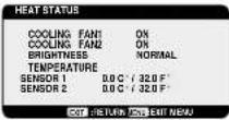 | Information of status for COOLING FAN, BRIGHTNESS and TEMPERATURE.COOLING FAN comes to run when inside temperature is over a guaranteed limit.BRIGHTNESS comes to be decreased when inside temperature is over guaranteed limit with cooling fun.In this case warning is displayed on the screen. |
| POWER ON DELAY | 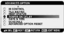 | 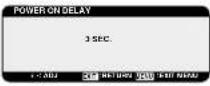 | Adjusts the delay time from "standby" to "power on" mode."POWER ON DELAY" time is selectable between 0 and 50 sec. |
| DATE & TIME | 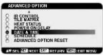 | 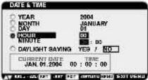 | Adjusts the current date and time for internal clock.You should set this function when you use "SCHEDULE". |
| SCHEDULE | 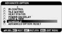 | 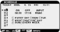 | Programs the monitor's working schedule.Schedule the power on and power off with hour and a day of the week. Also sets the input port.This OSM can't remove except EXIT.(see "NOTE 2" on page 26 for further information) |
| ADVANCED OPTION RESET | 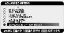 | 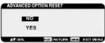 | Selecting ADVANCED OPTION reset allows you to reset all OSM settings from ADVANCED OPTION settings, except for DATE & TIME, and SCHEDULE.Select "YES" and press "SET" button to restore the factory preset data.Press "EXIT" button to cancel and then return the previous menu. |
NOTE 1: IMAGE PERSISTENCE
Please be aware that LCD Technology may experience a phenomena known as Image Persistence. Image Persistence occurs when a residual or "ghost" image of a previous image remains visible on the screen. Unlike CRT monitors, LCD monitors' image persistence is not permanent, but constant images being displayed for a long period of time should be avoided.
To alleviate image persistence, turn off the monitor for as long as the previous image was displayed. For example, if an image was on the monitor for one hour and a residual image remains, the monitor should be turned off for one hour to erase the image.
As with all personal display devices, NEC DISPLAY SOLUTIONS recommends displaying moving images and using a moving screen saver at regular intervals whenever the screen is idle or turning off the monitor when not in use.
Please set "SCREEN SAVER", "DATE &TIME" and "SCHEDULE" functions to further reduce the risk of Image persistence.
For long life use of Public Display
< Image Sticking of LCD Panel >
When LCD panel is operated continuously for long hours, a trace of electric charge remains near the electrode inside LCD, and residual or "ghost" image of previous image may be observed. (Image Persistence)
Image Persistence is not permanent, but when fixed image is displayed for long period, ionic impurities inside LCD are accumulated along the displayed image, and it is observed permanently. (Image Sticking)
For preventing the fast transition to Image Sticking, and for longer life usage of LCD, following are recommended.
- Fixed image should not be displayed for long period, and changed to another images with short cycle.
- When no use, please turn off the monitor by remote control, or use Power Management Function of monitor or use Schedule Function of monitor.
-
Reducing the environmental temperature is effective for long life use.
When Protection board (glass, acryl) is installed over the LCD surface, enclosed into the box / wall, or stack the monitor, please utilize the temperature sensors inside monitor.
To reduce the environmental temperature, the monitor should be set Low Brightness or Cooling Fan "ON" by using Screen sever Function. -
Please use "Screen Saver Mode" of monitor.
NOTE 2: HOW TO SETUP SCHEDULE
Using the "SCHEDULE" function allows you to set up to seven different scheduled time intervals when the LCD Monitor will be activated. You can select the time the monitor turns on and turns off, the day of week the monitor is activated, and which input source the monitor will use for each scheduled activation period. A check mark in the box next to the number of the schedule indicates that the selected schedule is in effect.
To select which schedule to set, use the up/down arrows to move the number (1 to 7) of the schedule.
Use the (+) and (-) buttons to move the cursor horizontally within the particular schedule. Use the (▲) and (▼) buttons to increase time and select input port. The "SET" button is used to make a selection.
If you create a schedule but do not want to use a power on time, select "--" in the "ON" time slot.
If you do not want to use a power off time select "--" in the OFF time slot.
If there is no input selected ("--" showing in the input spot) the input from the previous schedule will be used.
The selection of EVERY DAY within a schedule takes priority over other schedules that are set up to operate weekly.
When schedules are overlapping, scheduled Power ON time has priority over scheduled Power OFF time.
If there are two schedules programmed for the same time, then the highest numbered schedule has priority.
When the "OFF TIMER" (see page 23) is set, the "SCHEDULE" function is disabled.
Troubleshooting
No picture
- The signal cable should be completely connected to the display card/computer.
- The display card should be completely seated in its slot.
- Front Power Switch and computer power switch should be in the ON position.
- Check to make sure that a supported mode has been selected on the display card or system being used. (Please consult display card or system manual to change graphics mode.)
- Check the monitor and your display card with respect to compatibility and recommended settings.
- Check the signal cable connector for bent or pushed-in pins.
Power Button does not respond
- Unplug the power cord of the monitor from the AC outlet to turn off and reset the monitor.
Image persistence
- Please be aware that LCD Technology may experience a phenomenon known as Image Persistence. Image Persistence occurs when a residual or "ghost" image of a previous image remains visible on the screen. Unlike CRT monitors, LCD monitors' image persistence is not permanent, but constant images being displayed for a long period of time should be avoided. To alleviate image persistence, turn off the monitor for as long as the previous image was displayed. For example, if an image was on the monitor for one hour and a residual image remains, the monitor should be turned off for one hour to erase the image.
NOTE: As with all personal display devices, NEC DISPLAY SOLUTIONS recommends displaying moving images and using a moving screen saver at regular intervals whenever the screen is idle or turning off the monitor when not in use.
Image is unstable, unfocused or swimming is apparent
- Signal cable should be completely attached to the computer.
- Use the OSM Image Adjust controls to focus and adjust display by increasing or decreasing the fine adjustment. When the display mode is changed, the OSM Image Adjust settings may need to be re-adjusted.
- Check the monitor and your display card with respect to compatibility and recommended signal timings.
- If your text is garbled, change the video mode to non-interlace and use 60Hz refresh rate.
Image of component signal is greenish
- Check to see if the DVD/HD input connector is selected.
LED on monitor is not lit (no green or red colour can be seen)
- Power Switch should be in the ON position and power cord should be connected.
• Make certain the computer is not in a power-saving mode (touch the keyboard or mouse).
RED LED on monitor is blinking
• A certain failure might have occurred, please contact your nearest authorized NEC DISPLAY SOLUTIONS service facility.
Display image is not sized properly
- Use the OSM Image Adjust controls to increase or decrease the coarse adjustment.
- Check to make sure that a supported mode has been selected on the display card or system being used. (Please consult display card or system manual to change graphics mode.)
Selected resolution is not displayed properly
- Use OSM Display Mode to enter Information menu and confirm that the appropriate resolution has been selected. If not, select corresponding option.
No Sound
- Check to see if speaker cable is properly connected.
- Check to see if mute is activated.
- Check to see if volume is set at minimum.
Remote Control is not available
- Check the Remote Control's batteries status.
- Check if batteries are inserted correctly.
- Check if the Remote Control is pointing at the monitor's remote sensor.
- The remote control system may not function when direct sunlight or strong illumination strikes the remote control sensor of the LCD monitor, or when there is an object in the path.
"SCHEDULE"/"OFF TIMER" function is not working properly
- The "SCHEDULE" function will be disabled when the "OFF TIMER" is set.
- If the "OFF TIMER" function is enable and the power to the LCD monitor is turned off if the power supply is interrupted unexpectedly, then the "OFF TIMER" will be reset.
Either light vertical or horizontal stripes may appear, depending on the specific display pattern. This is no product fault or degradation.
English-27

natural_image
Two horizontal grayscale color swatches with a central crosshair and alignment lines (no text or symbols)
natural_image
Two isolated geometric symbols: a crosshair and a square with a dot, on a plain background (no text or labels)English-28
Rejstřík
Council Directive 89/336/EEC:
- EN 55022
- EN 61000-3-2
- EN 61000-3-3
- EN 55024
NEC Display Solutions, Ltd.
4-13-23, Shibaura, Minato-Ku
Tokyo 108-0023, Japan
natural_image
Pure electrical circuit lines without any symbolsnatural_image
3D rendering of a rectangular electronic device with a side-mounted bracket and mounting base (no text or symbols visible)natural_image
Coiled cable with two connectors (no text or symbols visible)natural_image
Pure geometric diagram showing a rectangle with a 30-degree angle and a small triangle below (no text or symbols)natural_image
Exterior view of a rectangular display panel mounted on a textured wall frame (no text or symbols visible)
natural_image
Simple line drawing of a cable with a connector, no text or symbols presentnatural_image
Close-up of an electronic device showing a cable inserted into a socket with connectors (no text or symbols visible)natural_image
3D rendering of a rectangular electronic device with mounting base and ventilation grilles (no text or symbols)4. Prevence pádu
Anschlüsse ....Deutsch-6
NEC Display Solutions, Ltd.
4-13-23, Shibaura,
Minato-Ku
Tokyo 108-0023, Japan
natural_image
Pure electrical circuit lines without any symbolsnatural_image
3D rendering of a rectangular electronic device with a flat screen and a small bracket (no text or symbols visible)natural_image
Coiled cable with two connectors (no text or symbols visible)natural_image
Simple line drawing of a rectangular frame with corner markers and a small triangular base (no text or symbols)
natural_image
Exterior view of a rectangular display panel mounted on a textured wall frame (no text or symbols visible)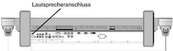
natural_image
Simple line drawing of a cable with a connector, no text or symbols presentnatural_image
Close-up of an electronic device showing a cable inserted into a port with multiple ports and a connector (no text or symbols visible)natural_image
3D rendering of a rectangular electronic device with mounting base and ventilation grilles (no text or symbols)natural_image
Pure geometric diagram with a rectangle and circular cutout, no text or symbols presentNEC Display Solutions, Ltd.
4-13-23, Shibaura,
Minato-Ku
Tokyo 108-0023, Japan
natural_image
Pure electrical circuit lines without any symbolsnatural_image
3D technical illustration of a rectangular electronic device with a small bracket and label (no readable text or symbols on the device itself)natural_image
Coiled cable with two connectors (no text or symbols visible)natural_image
Simple rectangular frame with corner markers and no visible text or symbolsnatural_image
Exterior view of a rectangular display panel mounted on a textured wall frame (no text or symbols visible)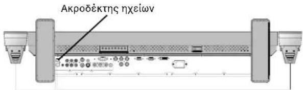
natural_image
Simple line drawing of a cable with a connector, no text or symbols presentnatural_image
Close-up of an electronic device showing a cable inserted into a port with connectors (no text or symbols visible)natural_image
3D rendering of a rectangular electronic device with mounting base and ventilation grilles (no text or symbols)natural_image
Pure geometric diagram with a rectangle and circle, no text or symbols presentΚατάσταση Εικόνας
RGB 1, 2, 3
HIGHBRIGHT→ STANDARD-sRGB
DVD/HD, VIDEO
HIGHBRIGHT → STANDARD → CINEMA
Πληροφορίες OSM
Directiva 89/336/CEE:
- EN 55022
- EN 61000-3-2
- EN 61000-3-3
- EN 55024
y lleva la marca

NEC Display Solutions, Ltd.
4-13-23, Shibaura,
Minato-Ku
natural_image
Pure electrical circuit lines without any symbolsEn la Unión europea
natural_image
3D rendering of a rectangular electronic device with a side-mounted bracket and mounting base (no text or symbols visible)Cubierta del interruptor principal
natural_image
Coiled cable with two connectors (no text or symbols visible)natural_image
Exterior view of a rectangular concrete structure with side supports and textured corners (no text or symbols)
natural_image
Simple line drawing of a cable with a connector, no text or symbols presentnatural_image
Close-up of an electronic device showing a cable inserted into a port with multiple ports and a cable outlet (no text or symbols visible)natural_image
3D rendering of a rectangular electronic device with front panel and mounting base (no text or symbols visible)NEC Display Solutions, Ltd.
4-13-23, Shibaura,
Minato-Ku
Tokyo 108-0023, Japon
natural_image
Pure electrical circuit lines without any symbolsnatural_image
3D rendering of a rectangular electronic device with a side panel and mounting bracket (no text or symbols)natural_image
Technical line drawing of a mechanical support or bracket (no text or symbols)natural_image
Coiled electrical plug and terminal outlet (no text or symbols visible)natural_image
Coiled cable with two connectors (no text or symbols visible)⑤ Bouton PICTURE MODE
⑨ Bouton PIP (Picture In Picture)
18 Bouton SET (fixer)
natural_image
Pure technical diagram of a rectangular panel with a 30-degree angle indicator and base mount (no text or symbols)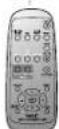
Comment installer le support
Comment retirer le support
natural_image
Exterior view of a rectangular display panel mounted on a textured wall frame (no text or symbols visible)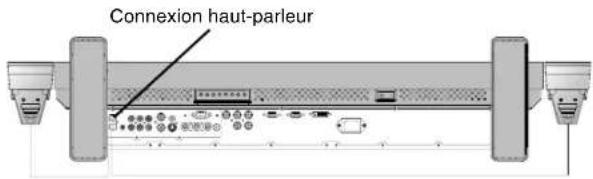
natural_image
Simple line drawing of a cable with a connector, no text or symbols presentnatural_image
Close-up of an electronic device showing a cable inserted into a port with multiple ports and connectors (no visible text or symbols)natural_image
3D rendering of a rectangular electronic device with mounting base and side panel (no text or symbols)natural_image
Pure geometric diagram with nested rectangles and circles, no text or symbols presentMode Image
RVB 1, 2, 3 HIGHBRIGHT STANDARD sRGB →
DVD/HD, Vidéo HIGHBRIGHT STANDARD CINEMA
NEC Display Solutions, Ltd. 4-13-23, Shibaura.
Minato-Ku
natural_image
Pure electrical circuit lines without any symbolsNell'Unione Europea
natural_image
3D rendering of a rectangular electronic device with a flat screen and a small bracket (no text or symbols visible)natural_image
Technical line drawing of a mechanical support structure (no text or symbols)natural_image
Coiled electrical plug and terminal outlet (no text or symbols visible)natural_image
Coiled cable with two connectors (no text or symbols visible)
Nucleo in ferrite x 2

Fascetta x 2
natural_image
Technical diagram of a rectangular panel with 30-degree angle annotations (no text or symbols on the panel itself)natural_image
Exterior view of a rectangular concrete structure with side supports and textured corners (no text or symbols)
natural_image
Simple line drawing of a cable with a connector, no text or symbols presentnatural_image
Close-up of an electronic device showing a cable inserted into a port with multiple ports and connectors (no visible text or symbols)natural_image
3D rendering of a rectangular electronic device with a flat panel and mounting base (no text or symbols visible)natural_image
Pure geometric diagram with a circle inside a rectangle and corner handles, no text or symbols present.Modalità immagine
RGB 1, 2, 3 HIGHBRIGHT STANDARD sRGB →
DVD/HD, VIDEO HIGHBRIGHT-STANDARD CINEMA
Informazioni OSM
MultiSync LCD3210 (L325RM) in overeenstemming
NEC Display Solutions, Ltd.
4-13-23, Shibaura,
Minato-Ku
Tokyo 108-0023, Japan
natural_image
Pure electrical circuit lines without any symbolsnatural_image
3D rendering of a rectangular electronic device with a side-mounted bracket and mounting base (no text or symbols visible)natural_image
Coiled cable with two connectors (no text or symbols visible)natural_image
Pure technical diagram of a rectangular panel with mounting feet and a 30-degree angle indicator (no text or symbols)natural_image
Exterior view of a rectangular display panel mounted on a textured wall frame (no text or symbols visible)
natural_image
Simple line drawing of a cable with a connector, no text or symbols presentnatural_image
Close-up of an electronic device showing a cable inserted into a port with multiple ports and a connector (no text or symbols visible)natural_image
3D rendering of a rectangular electronic device with mounting base (no text or symbols visible)4. Voorkomen dat de monitor valt
natural_image
Simple geometric diagram with a rectangle and an oval, no text or symbols presentBeeldmodus
RGB 1, 2, 3 HighbRIGHT* STANDARD* sRGB DVD/HD, VIDEO HighbRIGHT* → STANDARD* CINEMA*
*HIGHBRIGHT (zeer helder), STANDARD (standaard), CINEMA (bioscoop)
OSM-gegevens
NEC Display Solutions, Ltd.
4-13-23, Shibaura,
Minato-Ku
Tokyo 108-0023, Japan
natural_image
Pure electrical circuit lines without any symbolsW Unii Europejskiej
natural_image
3D rendering of a rectangular electronic device with a flat screen and a small bracket (no text or symbols visible)natural_image
Coiled cable with two connectors (no text or symbols visible)② Przycisk MUTE (WYCISZANIE)
⑥ Przycisk MUTE (WYCISZANIE)
natural_image
Simple line drawing of a rectangular frame with corner brackets and base supports (no text or symbols)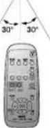
natural_image
Exterior view of a rectangular concrete structure with side supports (no text or symbols)
natural_image
Close-up of an electronic device showing a cable inserted into a port with multiple ports and a cable outlet (no text or symbols visible)natural_image
3D rendering of a rectangular electronic device with ventilation grilles and mounting base (no text or symbols)Image can be expanded beyond the active display area. The image which is outside of active display area is not displayed.
ZOOM
(POWIĘKSZENIE)
ZOOM
(POWIĘKSZENIE)
Tryb obrazu
RGB 1, 2, 3 HIGHBRIGHT* STANDARD sRGB

DVD/HD, VIDEO
HIGHBRIGHT* STANDARD CINEMA*
natural_image
Two horizontal grayscale color swatches with a central crosshair and alignment lines (no text or symbols)
natural_image
Two isolated geometric symbols: a crosshair and a square with crosshairs, both without any text or labels.Polski-20
Указатель
NEC Display Solutions, Ltd. 4-13-23, Shibaura, Minato-Ku Tokyo 108-0023, Japan

ME 06
natural_image
Pure electrical circuit lines without any symbolsnatural_image
3D rendering of a rectangular electronic device with a side panel and mounting bracket (no text or symbols)natural_image
Coiled cable with two connectors (no text or symbols visible)① Кнопка POWER
natural_image
Blank rectangular frame with corner brackets and a small triangular base (no text or symbols)Обращение с пультом
natural_image
Exterior view of a rectangular concrete structure with side supports and textured corners (no text or symbols)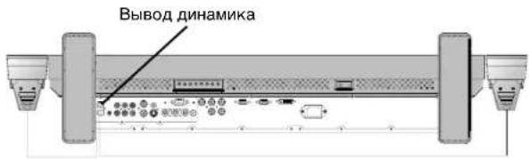
natural_image
Simple line drawing of a cable with a connector, no text or symbols presentnatural_image
Close-up of an electronic device showing a cable inserted into a socket with connectors (no text or symbols visible)natural_image
3D rendering of a rectangular electronic device with mounting base (no text or symbols visible)NEC Display Solutions, Ltd.
4-13-23, Shibaura,
Minato-Ku
Tokyo 108-0023, Japonya
natural_image
3D rendering of a rectangular electronic device with a side panel and mounting bracket (no text or symbols)Ana anahtar kapağı
natural_image
Coiled cable with two connectors (no text or symbols visible)Video Sinyal Kablosu (D-SUB - D-SUB Kablosu)
CD-ROM
Kullanıcı Kılavuzu

Vida (M4 x 8) x 4

Kıskac x 3

"SCREEN SAVER" (EKRAN KORUYUCU) (Bkz sayfa English-22), "SIDE BORDER COLOR" (YAN SINIR RENGİ) (Bkz sayfa English-22), "DATE & TIME" (TARİH & SAAT) (Bkz sayfa English-25), "SCHEDULE" (TAKVİM) (Bkz sayfa English-25).
natural_image
Exterior view of a rectangular display panel mounted on a textured wall frame (no text or symbols visible)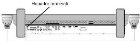
natural_image
Simple line drawing of a cable with a connector, no text or symbols presentnatural_image
Close-up of an electronic device showing a cable inserted into a port with multiple ports and a cable outlet (no text or symbols visible)natural_image
3D rendering of a rectangular electronic device with mounting base and ventilation grilles (no text or symbols)natural_image
Pure geometric diagram with a rectangle and circle, no text or symbols presentResim Modu
RGB 1, 2, 3 HIGHBRIGHT STANDARD sRGB
DVD/HD, VIDEO HIGHBRIGHT→ STANDARD→ CINEMA
STANDARD (STANDART), CINEMA (SİNEMA)
OSM Bilgisi
natural_image
Two horizontal grayscale color swatches with a central crosshair and alignment lines (no text or symbols)
natural_image
Two isolated geometric symbols: a crosshair and a circle with crosshairs, both without any text or labels.


NEC

Printed on recycled paper
Printed in China
Part No. ____

- 40" LCD Colour Monitor
- NEC
- DECLARATION OF CONFORMITY
- Canadian Department of Communications Compliance Statement
- FCC Information
- Index
- Important Information
- WARNING
- CAUTION
- Declaration
- Declaration of the Manufacturer
- Disposing of your old NEC product
- Within the European Union
- Outside the European Union
- Safety Precautions, Maintenance & Recommended Use
- FOR OPTIMUM PERFORMANCE, PLEASE NOTE THE FOLLOWING WHEN SETTING UP AND USING THE MULTISYNC LCD3210 LCD COLOUR MONITOR:
- Recommended Use
- Ergonomics
- Contents
- Parts Name and Functions
- ① POWER button (①)
- ② MUTE button
- ③ INPUT button
- ④ PLUS (+) button
- ⑤ MINUS (-) button
- ⑥ UP (▲ button
- ⑦ DOWN (▼ button
- ⑧ EXIT button
- ⑨ Remote control sensor and Power Indicator
- Main Power Switch
- Control Key Lock Mode
- Terminal Panel
- ① AC IN connector
- ② RGB 1 IN (DVI-D)
- ③ RGB 2 IN (mini D-Sub 15 pin)
- ④ RGB 3 IN [R, G, B, H, V] (BNC)
- ⑤ RGB OUT (mini D-Sub 15 pin)
- ⑥ DVD/HD IN (BNC)
- ⑦ AUDIO IN 1, 2, 3
- ⑧ AUDIO OUT
- ⑨ VIDEO IN/OUT
- ⑩ EXTERNAL CONTROL (mini D-Sub 9 pin)
- EXTERNAL SPEAKER TERMINAL
- Wireless Remote Control
- ① POWER button
- ② INPUT button
- ③ AUDIO INPUT button
- SIZE button
- ⑤ PICTURE MODE button
- ⑥ MUTE button
- ⑦ VOLUME UP button
- ⑧ VOLUME DOWN button
- ⑨ PIP (Picture In Picture) button
- STILL button
- DISPLAY button
- AUTO SETUP button
- MENU button
- UP button
- DOWN button
- MINUS button decrease
- PLUS button increase
- SET button
- EXIT button
- Operating Range for the Remote Control
- Handling the remote control
- Setup Procedure
- Determine the installation location
- Install the remote control batteries
- Connect external equipment (See pages 11-16)
- Connect the supplied power cord
- Switch on the power of all attached external equipment
- Operate the attached external equipment
- Adjust the sound
- Adjust the screen (See pages 18-25)
- Adjust the image (See pages 18-25)
- Recommended Adjustment
- When the monitor is installed in the portrait position
- Installing and removing stand
- How to install stand
- How to remove the stand
- When using external speakers
- How to use the attached speaker plug
- How to Mount and Attach Options to the LCD Monitor
- In the upright position
- Lay the screen face down
- Ventilation Requirements for enclosure mounting
- To avoid falling down
- To prevent the main power switch from being changed
- Connections
- Before making connections:
- Connecting a Personal Computer
- Connect the LCD Monitor to a Personal Computer
- Connecting to a Macintosh Computer
- Connect the LCD Monitor to Macintosh
- Connecting with Digital Interface Equipment
- Connect the LCD Monitor to a Computer with a Digital Output
- Connecting a DVD Player with component out
- Connect the LCD Monitor to a DVD Player
- Connecting to a Stereo Amplifier
- Connect the LCD Monitor to a Stereo Amplifier
- Basic Operation
- Power ON and OFF Modes
- Pressing the power button.
- Using the remote control.
- Pressing the Main Power Switch.
- Using Power Management
- Selecting a video source
- To view a video source:
- Picture Size
- Picture Mode
- Information OSM
- OSM (On-Screen-Manager) Controls
- NOTE 1: IMAGE PERSISTENCE
- For long life use of Public Display
- < Image Sticking of LCD Panel >
- NOTE 2: HOW TO SETUP SCHEDULE
- Troubleshooting
- No picture
- Power Button does not respond
- Image persistence
- Image is unstable, unfocused or swimming is apparent
- Image of component signal is greenish
- LED on monitor is not lit (no green or red colour can be seen)
- RED LED on monitor is blinking
- Display image is not sized properly
- Selected resolution is not displayed properly
- No Sound
- Remote Control is not available
- "SCHEDULE"/"OFF TIMER" function is not working properly
- English-27
- Rejstřík
- Prevence pádu
- Κατάσταση Εικόνας
- Πληροφορίες OSM
- En la Unión europea
- ⑤ Bouton PICTURE MODE
- ⑨ Bouton PIP (Picture In Picture)
- Bouton SET (fixer)
- Comment installer le support
- Comment retirer le support
- Mode Image
- Nell'Unione Europea
- Modalità immagine
- Informazioni OSM
- Voorkomen dat de monitor valt
- Beeldmodus
- OSM-gegevens
- W Unii Europejskiej
- ⑥ Przycisk MUTE (WYCISZANIE)
- Tryb obrazu
- Указатель
- ① Кнопка POWER
- Обращение с пультом
- Resim Modu
- OSM Bilgisi
Brand : NEC
Model : MultiSync LCD3210
Category : TV