
MultiSync E554 - Television NEC - Free user manual and instructions
Find the device manual for free MultiSync E554 NEC in PDF.


| Product Type | Professional Display / TV |
| Brand | NEC |
| Model | MultiSync E554 |
| Screen Size (Diagonal) | 55 inches (139.7 cm) |
| Display Resolution | 3840 x 2160 (4K UHD) |
| Panel Type | IPS or VA (IPS likely) |
| Brightness (Typical) | 350 cd/m² |
| Contrast Ratio | 1200:1 (Typical) |
| Response Time | 8 ms (Gray-to-Gray) |
| Viewing Angle (H/V) | 178° / 178° |
| Power Consumption (Typical) | 120 W |
| Power Consumption (Standby) | < 0.5 W |
| Input Voltage | 100-240 V AC, 50/60 Hz |
| Dimensions (W x H x D) with Stand | 1240 x 780 x 280 mm (approx.) |
| Weight (with Stand) | 18.5 kg (approx.) |
| VESA Mounting | 400 x 400 mm |
| Connectivity Inputs | HDMI x2, DisplayPort, VGA, USB, Audio In |
| Connectivity Outputs | Audio Out, RS-232C |
| Operating Temperature | 0°C to 40°C (32°F to 104°F) |
| Speakers | Integrated 10W x2 (approx.) |
| Key Features | 4K UHD, Slim Bezel, Professional Grade, 24/7 Operation |
Frequently Asked Questions - MultiSync E554 NEC
User questions about MultiSync E554 NEC
0 question about this device. Answer the ones you know or ask your own.
Ask a new question about this device
Download the instructions for your Television in PDF format for free! Find your manual MultiSync E554 - NEC and take your electronic device back in hand. On this page are published all the documents necessary for the use of your device. MultiSync E554 by NEC.
USER MANUAL MultiSync E554 NEC
natural_image
Line drawing of a flat-screen monitor with blank screen area (no text or symbols)E654
E554
E464
E424
E324
Index
Precautions And Reminders.... English-1
Important Safety Instructions.... English-2
Important Information .... English-5
Declaration Of Conformity ....English-11
Contents ...... English-13
Preparation.... English-14
Attaching the Base .... English-14
Using Cable Clamper ...... English-15
Preparing Your LCD TV For Wall Mounting (optional)......English-15
Prohibit Portrait Condition Use....English-16
Place The TV On A Solid Surface ...... English-17
Antenna Connection....English-17
Battery Installation and Replacement...... English-18
Connect To The Power Source ...... English-18
Power On/Off Your New LCD TV ...... English-19
Power Mode Status....English-19
Source Connection Guide ...... English-20
Operating Instructions ...... English-24
Using The Side Panel Controls .... English-24
Using The Remote Control......English-25
Operating Range for the Remote Control...... English-26
Timing Table ...... English-27
Navigating The On-Screen Menu.... English-28
Video Menu ...... English-28
Audio Menu ...... English-29
Channels Menu ...... English-29
Setup Menu.... English-30
Photos Menu .... English-31
Maintenance and Recycling ...... English-33
Care Of The Screen ...... English-33
Mobile Telephone Warning ...... English-33
End Of Life Directives...... English-33
Manufacturer's Recycling and Energy Information......English-34
Disposing of your old NEC product ...... English-34
Energy Saving...... English-34
Product Specification.... English-35
RS-232C Port Specifications.... English-41
Before Calling Service.... English-42
Glossary ...... English-43
Limited Warranty ...... English-44
References ...... English-46
Precautions And Reminders


Notice for Remote Controller
Avoid Liquids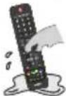 | Avoid Aerosol Cleaners | Avoid Dropping |
English-1
Read before operating equipment
Follow all warnings and instructions marked on this TV.
- Read these instructions.
- Keep these instructions.
- Heed all warnings.
- Follow all instructions.
-
Do not use this apparatus near water.
-
Clean only with dry cloth.
-
Do not block any ventilation openings. Install in accordance with the manufacturer's instructions.
-
Do not install near any heat sources such as radiators, heat registers, stoves, or other apparatus (including amplifiers) that produce heat.
-
Do not defeat the safety purpose of the polarized or grounding-type plug. A polarized plug has two blades with one wider than the other. A grounding type plug has two blades and a third grounding prong. The wide blade or the third prong are provided for your safety. If the provided plug does not fit into your outlet, consult an electrician for replacement of the obsolete outlet.
-
Protect the power cord from being walked on or pinched particularly at plugs, convenience receptacles, and the point where they exit from the apparatus.
-
Only use attachments / accessories specified by the manufacturer.
-
Use only with the cart, stand, tripod, bracket, or table specified by the manufacturer, or sold with the apparatus. When a cart is used, use caution when moving the cart/apparatus combination to avoid injury from tip-over.

-
Unplug this apparatus during lightning storms or when unused for long periods of time.
-
Refer all servicing to qualified service personnel. Servicing is required when the apparatus has been damaged in any way, such as power-supply cord or plug is damaged, liquid has been spilled or objects have fallen into the apparatus, the apparatus has been exposed to rain or moisture, does not operate normally, or has been dropped. Unplug immediately if the monitor faces above condition.
-
The TV complies with the recommended safety standards for stability. Do not put excessive force on the front or top of the cabinet. This could cause the product to tip over and cause damage and / or personal injury.
-
If monitor or glass is broken, do not come in contact with the liquid crystal and handle with care.
-
Follow instructions for wall, shelf or ceiling mounting as recommended by the manufacturer.
- An outdoor antenna should not be located near overhead power lines or any electrical circuits.
- If an outside antenna is connected to the receiver, confirm that the antenna system is grounded to protect against voltage surges and built up static charges. Section 810 of the National Electric Code, ANSI / NFPA No. 70-1984, provides information with respect to proper grounding for the mast and supporting structure, grounding of the lead-in wire to an antenna discharge unit, size of grounding connectors, location of antenna discharge unit, connection to grounding electrodes and requirements for the grounding electrode.
- Rest your eyes periodically by focusing on an object at least 5 feet away. Blink often.
- Do not place any heavy objects on the power cord. Damage to the cord may cause shock or fire.
- Do not use monitor in high temperature, humid, dusty, or oily areas.
- Do not bend, crimp or otherwise damage the power cord.
- Apparatus shall not be exposed to dripping or splashing and no objects filled with liquids, such as vases, shall be placed on the apparatus.
NOTE: To the TV system installer: This reminder is provided to call attention to Article 820-44 of the National Electric Code that provides guidelines for proper grounding and, in particular, specifies that the cable ground shall be connected to the grounding system of the facility, as reasonably close to the point of cable entry as possible

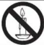
WARNING: To prevent the spread of fire, keep candles or other open flames away from this product at all times.
IMPORTANT INFORMATION
If a television is not positioned in a sufficiently stable location, it can be potentially hazardous due to falling. Many injuries, particularly to children, can be avoided by taking simple precautions such as:
- Using cabinets or stands recommended by the manufacturer of the television.
- Only using furniture that can safely support the television.
- Ensuring the television is not overhanging the edge of the supporting furniture.
- Not placing the television on tall furniture (for example, cupboards or bookcases) without anchoring both the furniture and the television to a suitable support.
- Not standing the televisions on cloth or other materials placed between the television and supporting furniture.
• Educating children about the dangers of climbing on furniture to reach the television or its controls.
Important Information

WARNING

TO PREVENT FIRE OR SHOCK HAZARDS, DO NOT EXPOSE THIS UNIT TO RAIN OR MOISTURE. ALSO, DO NOT USE THIS UNIT'S POLARIZED PLUG WITH AN EXTENSION CORD RECEPTACLE OR OTHER OUTLETS UNLESS THE PRONGS CAN BE FULLY INSERTED. REFRAIN FROM OPENING THE CABINET AS THERE ARE HIGH VOLTAGE COMPONENTS INSIDE. REFER SERVICING TO QUALIFIED SERVICE PERSONNEL.

CAUTION

CAUTION:
TO REDUCE THE RISK OF ELECTRIC SHOCK, MAKE SURE POWER CORD IS UNPLUGGED FROM WALL SOCKET. TO FULLY DISENGAGE THE POWER TO THE UNIT, PLEASE DISCONNECT THE POWER CORD FROM THE AC OUTLET. DO NOT REMOVE COVER (OR BACK). NO USER SERVICEABLE PARTS INSIDE. REFER SERVICING TO QUALIFIED SERVICE PERSONNEL.

This symbol warns user that uninsulated voltage within the unit may have sufficient magnitude to cause electric shock. Therefore, it is dangerous to make any kind of contact with any part inside this unit.

This symbol alerts the user that important literature concerning the operation and maintenance of this unit has been included. Therefore, it should be read carefully in order to avoid any problems.
CAUTION: Please use the power cord provided with this TV in accordance with the table below. If a power cord is not supplied with this equipment, please contact your supplier.
| Plug Type | Plug Shape | Region | Voltage |
| North America |  | U.S.A./Canada AC 120 V |
Power source
This LCD TV operates on 120 volts 60 Hz, AC current. Insert the power cord into a 120 volts 60 Hz outlet. The mains plug is used as the disconnect device and shall remain readily operable.
To prevent electric shock from the TV, do not use with an extension cord, receptacle, or other outlet unless the blades and ground terminal can be fully inserted to prevent blade exposure.
Never connect the LCD TV to 50 Hz, direct current, or anything other than the specified voltage.
CAUTION: Never remove the back cover of the LCD TV as this can expose you to very high voltages and other hazards. If the TV does not operate properly, unplug the LCD TV and call your authorized dealer or service center.
Adjust only those controls that are covered in the instructions, as improper changes or modifications not expressly approved by NEC could void the user's warranty.
Batteries installed warning
CAUTION: Incorrect usage of batteries can result in leaks or bursting.
NEC recommends the following battery use:
- Do not mix battery brands.
- Danger of explosion if battery is incorrectly replaced. Replace only with the same or equivalent type.
- Do not combine new and old batteries. This can shorten the battery life or cause liquid leakage of the batteries.
- Remove dead batteries immediately to prevent battery acid from leaking into the battery compartment.
- Do not touch exposed battery acid as it may injure skin.
- Remove the batteries if you do not intend to use the remote control for a long period of time.
- The batteries shall not be exposed to excessive heat such as sunshine, fire or the like.
Image persistence
- Please be aware that LCD Technology may experience a phenomenon known as Image Persistence.
Image Persistence occurs when a residual or "ghost" image of a previous image remains visible on the screen.
Unlike CRT monitors, LCD monitors' image persistence is not permanent, but constant images being displayed for a long period of time should be avoided.
To alleviate image persistence, turn off the monitor for as long as the previous image was displayed.
For example, if an image was on the monitor for one hour and a residual image remains, the monitor should be turned off for one hour to erase the image.
NOTE: As with all personal display devices, NEC DISPLAY SOLUTIONS recommends displaying moving images and using a moving screen saver at regular intervals whenever the screen is idle or turning off the monitor when not in use.
CAUTION:
These servicing instructions are for use by qualified service personnel only. To reduce the risk of electric shock, do not perform any servicing other than that contained in the operating instructions unless you are qualified to do so.
Ventilation
The slots and openings in the TV are provided for necessary ventilation. To ensure reliable operation of the TV and to protect it from overheating, these slots and openings must never be blocked or covered.
Unless proper ventilation is provided, the TV may gather dust and get dirty. For proper ventilation, observe the following:
- Do not install the TV face up, down or sideways.
- Do not install the TV turned over or upside down.
- Never cover the slots and openings with a cloth or other materials.
- Never block the slots and openings by placing the TV on a bed, sofa, rug or other similar surface.
- Never place the TV in a confined space, such as a bookcase or built-in cabinet, unless proper ventilation is provided.
Leave some space around the TV set as shown below. Otherwise, air-circulation may be inadequate and will cause overheating, which may cause a fire or damage to the TV set.
Install on the wall

For use only with UL Listed Wall Mount Bracket with minimum weight / load: Please refer to the Specification on page 36 and page 39.
Unit without base weight: The equipment and its associated mounting means still remain secure during the test.
Used wall mounting kit, VESA-compatible wall bracket distance, diameter of Screw dimension: Please refer to the Specification on page 36 and page 39.
Installed with stand
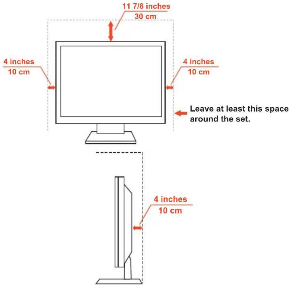
Never install the TV set where air-circulation is blocked.
Objects and ventilation holes
Never push objects of any kind into the TV through the cabinet slots as they may touch dangerous voltage points or short out parts that could result in a fire or an electric shock. Do not place any objects on the TV.
License Notice and Trademark Acknowledgement
Windows is a registered trademark of Microsoft Corporation.
NEC is a registered trademark of NEC Corporation.
All other brands and product names are trademarks or registered trademarks of their respective owners.

HIGH-DEFINITION MULTIMEDIA INTERFACE
HDMI, the HDMI logo and High-Definition Multimedia Interface are trademarks or registered trademarks of HDMI Licensing LLC in the United States and other countries.

(Only for E554/E464/E424/E324)
Please keep the factory default settings as shipped, in which the product can meet ENERGY STAR ^® requirements.

Manufactured under license from Dolby Labortories. Dolby and the double-D symbol are trademarks of Dolby Laboratories.
Declaration Of Conformity
This device complies with Part 15 of FCC Rules. Operation is subject to the following two conditions. (1) This device may not cause harmful interference, and (2) this device must accept any interference received, including interference that may cause undesired operation.
U.S. Responsible Party: NEC Display Solutions of America, Inc.
Address: 500 Park Boulevard, Suite 1100 Itasca, Illinois 60143
Tel. No.: (630) 467-3000
Type of Product: LCD TV
Equipment Classification: Class B Peripheral
Model: E654
E554
E424
E464
E324

We hereby declare that the equipment specified above conforms to the technical standards as specified in the FCC Rules.
Canadian Department of Communications Compliance Statement
DOC: This Class B digital apparatus meets all requirements of the Canadian Interference-Causing Equipment Regulations.
C-UL: Bears the C-UL Mark and is in compliance with Canadian Safety Regulations according to CAN/CSA C22.2 No. 60065-03.
FCC Information:
- Use the attached specified cables with the E654/E554/E464/E424/E324 color monitor so as not to interfere with radio and television reception.
(1) Please use the supplied power cord or equivalent to ensure FCC compliance.
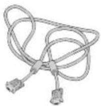
(2) Please use the supplied shielded video signal cable, Mini D-SUB 15 pin to Mini D-SUB 15 pin.
-
This equipment has been tested and found to comply with the limits for a Class B digital device, pursuant to part 15 of the FCC Rules. These limits are designed to provide reasonable protection against harmful interference in a residential installation. This equipment generates, uses and can radiate radio frequency energy and, if not installed and used in accordance with the instructions, may cause harmful interference to radio communications. However, there is no guarantee that interference will not occur in a particular installation. If this equipment does cause harmful interference to radio or television reception, which can be determined by turning the equipment off and on, the user is encouraged to try to correct the interference by one or more of the following measures:
-
Reorient or relocate the receiving antenna.
- Increase the separation between the equipment and receiver.
- Connect the equipment into an outlet on a circuit different from that to which the receiver is connected.
- Consult the dealer or an experienced radio / TV technician for help.
FCC CAUTION
To assure continued compliance and possible undesirable interference, ferrite cores may be used when connecting this LCD TV to video equipment; and maintain at least 400mm spacing to other peripheral device.
FCC warning
Changes or modifications not expressly approved by the party responsible for compliance with the FCC Rules could void the user's authority to operate this equipment.
Cables
Connections to this device must be made with shielded cables with metallic RF / EMI connector hoods to maintain compliance with FCC Rules and Regulations.
Canadian notice
CAN ICES-3 (B) / NMB-3(B)
If necessary, the user should contact the dealer or an experienced radio/television technician for additional suggestions. The user may find the following booklet, prepared by the Federal Communications Commission, helpful: "How to Identify and Resolve Radio-display Interference Problems." This booklet is available from the U.S. Government Printing Office, Washington, D.C., 20402, Stock No. 004-000-00345-4.
Contents
Your new NEC monitor box ^*1 should contain the following:
- Monitor (1)
• TV Stand base (1) - Screws for TV base (4)
- Remote control (1)
• 1.5 V AAA batteries (2) - Power cord (1)
• D-sub cable (1) - User's manual (1)
E654
natural_image
Blank whiteboard with gray border (no text or symbols)E554 / E464 / E424 / E324

natural_image
Blank whiteboard with a gray border (no text or symbols)
Power Cord

Wireless Remote Control and AAA Batteries
natural_image
Coiled cable or wire with two connectors (no text or symbols visible)Video Signal Cable (Mini D-SUB 15 pin to Mini D-SUB 15 pin)
natural_image
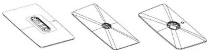
Three technical line drawings of a rectangular device with internal components, shown from different angles (no text or symbols)(E654) (E554) (E464/E424/E324)
Stand Base

Stand Screw x 4

User's Manual
NOTE:
*1: Remember to save your original box and packing material to transport or ship the monitor.
Preparation
IMPORTANT: Do not apply pressure to the TV screen display area which may compromise the integrity of the display. The manufacturer's warranty does not cover user abuse or improper installations.
Attaching the Base
E654

natural_image
Technical line drawing of a computer monitor with internal circuitry and mounting bracket (no text or symbols)E554 / E464 / E424 / E324

natural_image
Diagram of a flat-screen monitor with a handle and a separate view showing internal components (no text or symbols)- Place the TV face down on a soft and flat surface to prevent scratching and damage.
- Carefully align the base to the stand and fasten the screws with a cross-head screwdriver.
CAUTION: The base of the stand is very heavy. Install with care to avoid injury such as dropping the base onto one's foot.
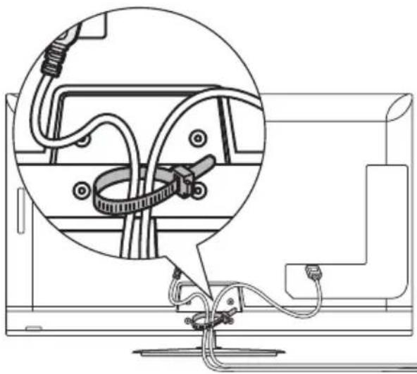
Using Cable Clamper
Tie the cables together using the cable clamper.
natural_image
Diagram of cable connections inside a computer monitor, showing cable routing and cable attachment (no text or labels)Preparing Your LCD TV For Wall Mounting (optional)
We suggest that you keep your TV at least 2.36 inches (60 mm) from the wall to prevent cable interference. Before mounting your TV on the wall, you need to remove the base. For your safety, only mount with a UL listed wall mount bracket that supports the weight of the TV.(Please see page 36 and page 39)
To attach a wall mount bracket to your TV:
E654
step 1 step 2

natural_image
Technical line drawing showing two views of a device's internal structure, with no visible text or symbols.- Loosen the screws at the bottom of the base, and remove the base.
- Loosen the screws at the bottom of the stand to remove the stand.
- Secure the wall mount bracket to the back of your TV using four M6 screws.
| screen size (inches) required pitch (mm) require mounting bolts | ||
| 65 400 | × 400 4 | × M6 (25mm) |
CAUTION: If you skip the step 1 and loosen the screws for stand directly, please be sure to hold the base tightly to avoid dropping the base.
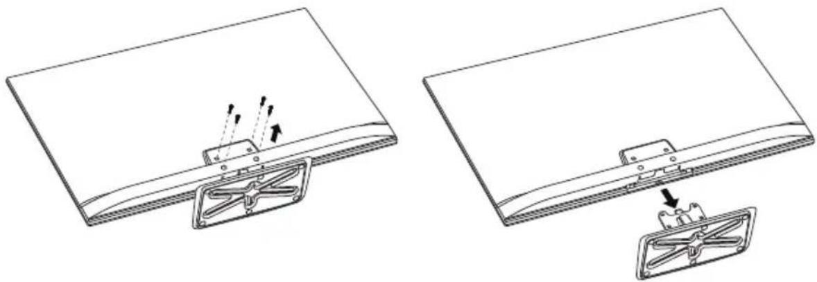
E554/E464/E424/E324
natural_image
Technical line drawing showing two views of a flat panel with internal components and directional arrows indicating motion (no text or symbols)- Loosen the screws on the back of the stand-base, and remove the base.
- Secure the wall mount bracket to the back of your TV using four M4 screws (for 32" only) or M6 screws (for 42"/46"/55" only).
| screen size (inches) required pitch (mm) require mounting bolts | ||
| 55 400 | × 400 4 | × M6 (18mm) |
| 46 400 | × 400 4 | × M6 (18mm) |
| 42 400 | × 400 4 | × M6 (18mm) |
| 32 100 | × 100 4 | × M4 (18mm) |
NOTE:
Wall mounting solution is not included with the unit and is sold separately. Contact your NEC representative for details.
Prohibit Portrait Condition Use

flowchart
graph TD
    A[" "] --> B[" "]
    style A fill:#fff,stroke:#000
    style B fill:#fff,stroke:#000
CAUTION:
Do not rotate the display from landscape to portrait.
Place The TV On A Solid Surface
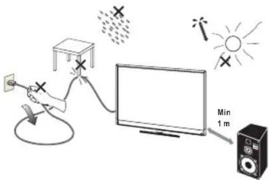
Ensure that the LCD TV is placed in a position to allow free flow of air.
Do not cover the ventilation openings on the back cover.
Do not place the TV near any open flames.
Do not allow the TV to be placed in an environment where it can be exposed to heat, direct sunlight, or rain and water.
Do not expose the equipment to any liquid.
Antenna Connection
Unless your LCD TV is connected to a cable TV system or to a centralized antenna system, a good outdoor color TV antenna is recommended for best television performance. However, if you are located in an exceptionally good signal area that is free from interference and multiple image ghosts, an indoor antenna may be sufficient.

When using a 75-Ohm coaxial cable system, connect the CATV coaxial cable to the AIR/CABLE (75-Ohm) terminal. Or if you have an antenna, connect the coaxial cable to the same AIR/CABLE terminal.
Battery Installation and Replacement
The remote control is powered by two 1.5V AAA batteries. To install or replace batteries:
- Open the battery cover of the remote control by pushing and pulling it in the direction of the arrow.
- Insert two new "AAA" size batteries for the remote control. When replacing old batteries, push them towards the springs and lift them out.
- Match the batteries to the (+) and (-) marks in the battery compartment.
- Insert the bottom of the battery, the (-) side, into the battery compartment first, push towards the springs and insert the top of the battery, the (+) side, into place. Do not force the battery into the battery compartment.
- Close the battery cover making sure the tabs rest in the corresponding holes and push down the cover until it clicks shut.

natural_image
Diagram showing battery charging process with red arrows indicating movement from left to right (no text or symbols)Connect To The Power Source
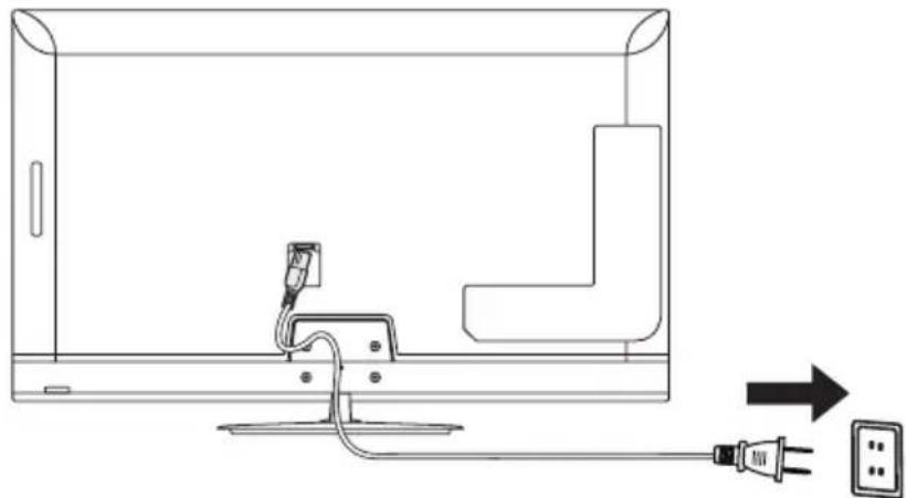
The TV should be installed close to an easily accessible power outlet. Fully insert the prongs into the power outlet socket. A loose connection may cause image degradation.
natural_image
Line drawing of a TV cable with plug and power outlet, showing connection to a terminal (no text or symbols)If there is power to the TV, the front LED at the bottom of the TV will be either none or red. A red LED means the TV is in standby mode.
Power On/Off Your New LCD TV
Press the power button on the remote control or press the power button located on the side of the TV. The TV will power on.

Power Mode Status
| Mode On Standby Warming up | |||
| LED Status | None | Red | Blinking Red |
Warming up mode can automatically turn the Monitor power on when signal appears.
Press the power button on remote control or on side keypad can power on the Monitor in standby mode.
Source Connection Guide E654
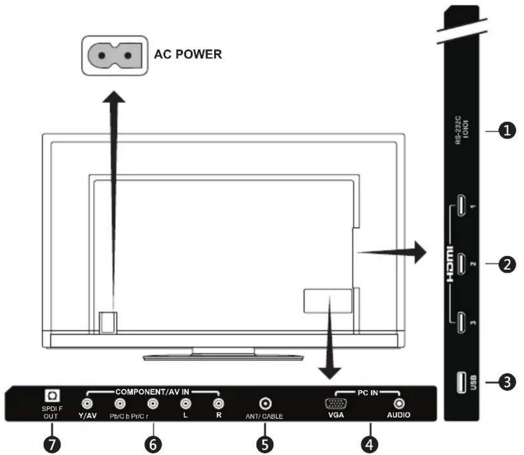
- RS-232C – Input from external equipment such as a PC or AV control system in order to control RS-232C functions.
- HDMI (HDMI1, HDMI2, HDMI3) – Connect your HDMI devices.
- USB port – Used for accessing JPEG photo files.
- PC IN (VGA / AUDIO) – Connect your PC video and audio.
- ANT / CABLE – Connect an RF antenna or Analog Cable system.
- COMPONENT / AV IN -
- Component: Connect digital video equipment to the Video Green (Y), Blue (Pb), Red (Pr) jacks, and matching Audio White (L) and Red (R) jacks.
- Composite: Connect digital video equipment to the Video Green (AV), jacks, and matching Audio White (L) and Red (R) jacks.
- SPDIF OUT- Use a digital audio cable to connect stereo home theater system.
E554

- RS-232C – Input from external equipment such as a PC or AV control system in order to control RS-232C functions.
- HDMI (HDMI1, HDMI2, HDMI3) – Connect your HDMI devices.
- USB port – Used for accessing JPEG photo files.
- PC IN (VGA / AUDIO) – Connect your PC video and audio.
- ANT / CABLE – Connect an RF antenna or Analog Cable system.
- COMPONENT / AV IN -
- Component: Connect digital video equipment to the Video Green (Y), Blue (Pb), Red (Pr) jacks, and matching Audio White (L) and Red (R) jacks.
- Composite: Connect digital video equipment to the Video Green (AV), jacks, and matching Audio White (L) and Red (R) jacks.
- SPDIF OUT- Use a digital audio cable to connect stereo home theater system.

- RS-232C – Input from external equipment such as a PC or AV control system in order to control RS-232C functions.
- USB port – Used for accessing JPEG photo files.
- HDMI (HDMI1, HDMI2, HDMI3) – Connect your HDMI devices.
- ANT / CABLE – Connect an RF antenna or Analog Cable system.
- SPDIF OUT- Use a digital audio cable to connect stereo home theater system.
- COMPONENT / AV IN -
- Component: Connect digital video equipment to the Video Green (Y), Blue (Pb), Red (Pr) jacks, and matching Audio White (L) and Red (R) jacks.
- Composite: Connect digital video equipment to the Video Green (AV), jacks, and matching Audio White (L) and Red (R) jacks.
- PC IN (VGA / AUDIO) – Connect your PC video and audio.
Once your AV device is connected, press the Source button on the remote control to select the relevant source to view. (ex: Press COMP button to select "Component" if you have connected a source to the Component input.)


Operating Instructions

Using The Side Panel Controls
| 1. VOL + | Press to increase the volume.Press this button to shift Right in the OSD menu. | |
| 2. VOL - | Press to decrease the volume.Press this button to shift Left in the OSD menu. | |
| 3. CH ^ | Press to change channels.Press this button to shift up in the OSD menu. | |
| 4. CH √ | Press to change channels.Press this button to shift down in the OSD menu. | |
| 5. | MENU | Press to open or exit the OSD (On-Screen Display) menu. |
| 6. INPUT Press | to select the input source. | |
| 7. | POWER | Press to turn on / off (standby) the TV. |
Using The Remote Control
(Power)
Press to turn On/Off (standby) the power. (NOTE: To completely turn off the power, unplug the power cord from the power outlet.)
TV
Press to choose ATSC/NTSC tuner source mode.
AV
Press to choose Composite source mode.
COMP
Press to choose Component source mode.
HDMI/PC
Press repeatedly to choose PC IN or HDMI source mode.
$$ 0 \sim 9 / - $$
Press to select channel (Press "—" to choose the sub-channel).
PRE CH
Press to display the previous channel.
Source
Press repeatedly to choose the various input sources.
Mute
Switch the sound On / Off.
$$ \mathrm{VOL} + / \mathrm{VOL} - $$
Press + or — to adjust the volume.
$$ \mathrm{CH} + / \mathrm{CH} - $$
Press + or — to browse through the channels.
Exit
Press to exit the OSD menu.
Display
Press to show the information about the input source and tuner channel.
FAV
Press to display the Favorite List.

Menu
Press to open the OSD menu.
$$ \blacktriangle , \blacktriangledown , \blacktriangleleft , \blacktriangleright , \mathrm{OK} $$
Press to select or confirm the various function items on the menu.
Color buttons
Follow the on-screen instruction to operate.
MTS
Press to activate the NTSC tuner sounds such as Stereo, SAP, Monotone, and languages of the digital tuner.
Wide
Press to choose the display aspect ratio: Normal / Zoom / Wide / Cinema / Auto (Ratio availability varies by video inputs.)
Picture
Press to choose the picture mode: Dynamic / Standard / Energy Savings / Theater / Game (Only for E654/E554 model) / Custom.
Audio
Press to choose sound mode: Standard / Movie / Music / News / Custom.
CH-List
Press to display the Channel List.
c c
Press to activate the Closed Caption.
Operating Range for the Remote Control
Point the top of the remote control toward the LCD TV's remote sensor during button operation.
Use the remote control within a distance of about 7 m (23 ft.) from remote control sensor or at a horizontal and vertical angle of within 30^ within a distance of about 3.5 m (10 ft.).
E654 E554 / E464 / E424 / E324

CAUTION:
Important, the remote control system may not function when direct sunlight or strong illumination strikes the remote control sensor or when there is an object in the path.
Timing Table
| Resolution | WXGA (E324) | FHD (E654/E554/E464/E424) | Horizontal Vertical | Nominal Pixel Clock (MHz) | |||||
| VGA DVI | VGA DVI | Nominal Freq. (kHz) | Sync Polarity | Nominal Freq. (Hz) | Sync Polarity | ||||
| 640 × 480@60Hz | ● | ● | ● | ● | 31.469 | - | 59.94 | - | 25.175 |
| 720 × 400@70Hz | ● | ● | ● | ● | 31.469 | - | 70.087 | + | 28.322 |
| 800 × 600@60Hz | ● | ● | ● | ● | 37.879 | + | 60.317 | + | 40 |
| 1024 × 768@60Hz | ● | ● | ● | ● | 48.363 | - | 60.004 | - | 65 |
| 1280 × 720@60Hz | ● | ● | ● | ● | 45 | - | 60 | + | 74.25 |
| 1280 × 800@60Hz | ▲ | ▲ | ● | ● | 49.702 | - | 59.81 | + | 83.5 |
| 1366 × 768@60Hz | ● (Native) | ● (Native) | Not support | ● | 47.712 | + | 59.79 | + | 85.5 |
| 1920 × 1080@60Hz | ▲ | ▲ | ● (Native) | ● (Native) | 67.5 | + | 60 | + | 148.5 |
| Resolution | WXGA(E324) | FHD(E654/E554/E464/E424) | ||
| HDMI | Component | HDMI | Component | |
| 480i 60Hz | ● | ● | ● | ● |
| 480p 60Hz | ● | ● | ● | ● |
| 720p 60Hz | ● | ● | ● | ● |
| 1080i 60Hz | ▲ | ▲ | ● | ● |
| 1080p 24Hz | ▲ | Not support | ● | Not support |
| 1080p 30Hz | ▲ | Not support | ● | Not support |
| 1080p 60Hz | ▲ | Not support | ● | Not support |
NOTE:
▲: Use Down-scaling function. Image quality is limited.
Navigating The On-Screen Menu
Press the Menu button to display and Exit button to close the main menu. Use the Navigation Ring to navigate, select, adjust or confirm an item on the OSD (On-Screen Display) menu.
NOTE: Some features may only be available in a particular source mode.
Video Menu
Video Menu adjusts video items.

1. Picture Mode
Enter this menu to select from preset picture settings to optimize your TV's performance. Dynamic / Standard / Energy Savings / Theater / Game (Only for E654/E554 model) / Custom.
2. Brightness
Adjust picture brightness from 0 - 100.
3. Contrast
Adjust picture contrast from 0 - 100.
4. Color
Adjust picture color from 0 - 100.
5. Advanced Video
Select advanced video settings.
[Dynamic Backlight] (DCR)
Enhance the contrasts between darkness and brightness to optimization the picture.
[Color Temperature]
Select a choice from Cool, Normal, or Warm.
[Noise Reduction]
Set to reduce the video noise.
[Tint]
Adjust the hue (Red, Green, Blue) of the picture from R50 — G50.
[Sharpness]
Adjust object edges to optimize picture detail from 0 — 100.
[Adaptive Contrast]
Set to automatically adjust the picture detail and brightness.
[Aspect Ratio]
Adjust how the picture fills the screen.
Normal / Zoom / Wide / Cinema / Auto
[Overscan (On/Off)]
Set Off to show the full image on the TV when connecting a computer.
Set On to show the full image on the TV when not connected with a computer.
[Motion 120Hz]
(Only for E654/E554 model)
Eliminate motion blur with clear detail and smooth motion.
[Backlight]
Set the backlight brightness from 0 - 50.
6. Reset Video Settings
Reset video settings to factory default settings.
Audio Menu
Audio Menu provides an audio adjustment for user to modify the audio setting.

1. Sound Mode
Select preset audio modes. Standard / Movie / Music / News / Custom.
2. Balance
Adjust the audio balance for the TV's internal left and right speakers from L50 — R50.
3. Advanced Audio
Select advanced audio settings.
[Bass]
Enhance the low frequencies.
[Treble]
Enhance the high frequencies.
[Internal Speakers]
Select Off to turn off the internal speakers.
[Digital Output]
Select optical output options:
RAW or PCM (Only available for digital channels or HDMI input source)
[Audio Source]
Select audio sources in analog channels.
Mono / Stereo / SAP
(Only available for analog channels)
[Audio Language]
Select language options in digital channels. (Only available for digital channels)
4. Reset Audio Settings
Reset Audio settings to factory default settings.
Channels Menu
Channel Menu allows you to set your signal source options. According to various requirements in different source modes, certain features could be hidden (disabled) on the menu.

1. Auto Channel Scan
Automatically search the available channels.
2. Signal Strength
Access signal strength meter to help you adjust your antenna installation to optimize signal reception. (Only available for digital channels)
3. Add/Skip Channels
Manually add or skip channels to the channel list.
4. Favorite Channels
Add channels to your favorite channel list.
5. Channel Labels
Create labels to any channel.
6. Audio Only
Play the audio only when picture is turned off. Any press of the button except the ⏻ (Power) button on the remote control will turn on the picture.
7. Auto Aspect
Automatically adjust the picture aspect ratio according to the TV program.
Setup Menu
Setup Menu in TV mode is shown below. According to various requirements in different source modes, certain features could be hidden (disabled) on the menu.

1. Menu Language
Select the menu display language.
English / Français / Español
2. Parental Controls
Set TV parental controls. This function blocks out the picture and sound of the selected rating levels.
The factory preset password to enter Parental Controls feature is a 4-digit number 0000.
[Panel Lock]
Lock or unlock all buttons on the TV's panel.
[Block Unrated TV]
Block or unblock the unrated programs.
[US]
Set the parental control level using Movie Rating memu or TV Rating memu.
[Canadian]
Set the parental control level using Canadian English menu or Canadian French menu.
[Change Password]
Change the 4-digit password. You will have to enter the new password first, then enter again the new password to confirm. Make sure to keep your new password.
[Region 5]
Use Region 5 to block various types of movies and television programs based on ratings systems used in the USA that you feel may be inappropriate due to its content. The Region 5 option will operate for Digital Channels (ATSC) only.
[Reset Region 5]
Clear the downloaded RRT5 rating information and restore to the factory default settings.
3. Closed Caption
Adjust the Closed Caption settings.
Caption Display / Analog Captions / Digital Captions / Digital Caption Options
4. Sleep Timer
Select how long the TV will take to automatically turn intself off.
Off / 5 / 10 / 15 / 30 / 60 / 90 / 120 / 180 / 240 (minutes)
5. Input Labels
Create labels for the devices connected to your TV. (Only available for Non TV input source)
6. RGB Options
(Only available for VGA input, and when there is VGA signal input)
[Auto Adjust]
Automatically adjust the image settings such as position.
[H-Position]
Adjust horizontal position.
[V-Position]
Adjust vertical position.
[Clock]
Set to the minimum level if noise occurs.
[Phase]
Eliminate flicker and distortion.
[Reset RGB Options]
Reset RGB options to factory default settings.
7. System Info
Indicate the display information.
8. Energy Options
Select the power saving modes.
Home mode is intended for home use, and will save much energy.
Retail mode sets the TV to a more energy consuming mode.
9. Monitor ID
Set the monitor ID number from 1—100, All, or Group A—J.
10. Reset AV & Setup
Reset all Audio, Video, and Setup settings to factory default settings.
Photos Menu
You could easily browse images from USB device.

If no USB device is detected, TV will display the message: Please Insert USB flash driver.
1. Browse Photos
Browse photos in the USB flash drive.
2. Favorite Photos
Only display your favorite photos.
3. View Slideshow
View your photos in a slideshow manner.
4. Settings
Change the slidwshow settings. Repeat / Shuffle / Speed / Transition
To control while in photo folder:
- Press ▲, ▼, ◀, ► button to browse the photo files.
- Press OK button to open a folder or a photo file which will be viewed on the full screen.
- Press Menu button to return to USB Main Menu.
- Press FAV button to add a photo file to favorite list or delete from favorite list.
To control while in full-screen photo show:
- Press ▶ button to go to the next image. Press ◀ button to go to the previous image.
- Press OK button to rotate the image clockwise.
- Press Wide to zoom the image. The zoom function will switch between the 4 styles by cycle and "x1" "x2" "x4" "Fill" info bar will appear on the right / down corner of screen (If the image resolution over size will not aspect "x1").
- Press Menu button to return to the Folder / Photo List View.
To control while in photo slideshow:
- Press OK button to play or pause slideshow.
- Press Menu button to stop the slideshow and return to photo browser.
Data Format for USB Photo Viewer
| Data format | JPEG, JPG, JPE |
| Max. folder layer | 9 |
| Max. number of photos | 700 |
| Max. number of favorite photos | 200 |
| Min. image resolution | 75 × 75 pixels |
| Max. image resolution (Progressive DCT) | 1,024 × 768 pixels |
| Max. image resolution (Baseline Sequential DCT) | 15,360 × 8,640 pixels |
| Supported file system | FAT32 |
CAUTION:
- USB photo viewer only supports USB Mass storage class devices.
- A JPEG image modified with PC may not be displayed.
- Partly degraded files might be displayed at a reduced resolution.
- Not guaranteed to support all USB devices.
- Do not use a USB Hub.
- Do not support multi-partition USB.
NOTE:
- The folder and file names may be different depending on the digital camera used.
- Support USB 2.0 Type A connector (DC5V, max. 500mA). For USB device over 500mA, we suggest to use adaptor or external power.
Care Of The Screen
Do not rub or strike the screen with anything hard as this may scratch, mar, or even damage the screen permanently. Unplug the power cord before cleaning the screen. Dust the TV by wiping the screen and the cabinet with a soft, clean cloth. If the screen requires additional cleaning, use a clean, damp cloth. Do not use liquid cleaners, aerosol cleaners, or solvents of any kind.
Mobile Telephone Warning
Keep your mobile telephone away from your TV to avoid disturbances in the picture or sound, possibly causing permanent damage to your TV.
End Of Life Directives
In an effort to produce environmentally friendly products, your new TV contains materials that can be recycled and reused. At the end of your TV's life, specialized companies can minimize display waste by separating the reusable materials from non-reusable materials. Please ensure you dispose of your TV according to local regulations.
Manufacturer's Recycling and Energy Information
NEC DISPLAY SOLUTIONS is strongly committed to environmental protection and sees recycling as one of the company's top priorities in trying to minimize the burden placed on the environment. We are engaged in developing environmentally-friendly products, and always strive to help define and comply with the latest independent standards from agencies such as ISO (International Organisation for Standardization) and TCO (Swedish Trades Union).
Disposing of your old NEC product
The aim of recycling is to gain an environmental benefit by means of re-use, upgrading, reconditioning or reclamation of material. Dedicated recycling sites ensure that environmentally harmful components are properly handled and securely disposed. To ensure the best recycling of our products, NEC DISPLAY SOLUTIONS offers a variety of recycling procedures and gives advice on how to handle the product in an environmentally sensitive way, once it has reached the end of its life.
All required information concerning the disposal of the product and country-specific information on recycling facilities can be found on our following websites:
http://www.nec-display-solutions.com/greencompany/ (in Europe), http://www.nec-display.com (in Japan) or http://www.necdisplay.com (in USA).
Energy Saving
This TV features an advanced energy saving capability. When a VESA Display Power Management Signalling (DPMS) Standard signal is sent to the TV, the Energy Saving mode is activated. The TV enters a single Energy Saving mode.
| Mode Power consumption LED colour | ||
| On Mode(with USB, with Audio) | Approx. 260 W (E654)Approx. 122 W (E554)Approx. 100 W (E464)Approx. 85W (E424)Approx. 45 W (E324) | None |
| Standby Mode Less than 0.5 W Red | ||
Product Specification
This model complies with the specifications listed below.
Reorient or relocate the receiving display.
Designs and specifications are subject to change without notice.
This model may not be compatible with features and/or specifications that may be added in the future.
| Model Name E654 E554 | ||
| DISPL AY | ||
| Viewable 65" 55" | ||
| Resolution 1,920 | ×1,080 | |
| Color Over 16 million colors (depending on video card used) | ||
| Frequency | 31-83 KHz (Analog input)Horizontal: 15.625/15.734KHz, 31-83KHz (HDMI input) | |
| 56-75 Hz (Analog input)Vertical: 24Hz, 30Hz, 50Hz, 56Hz - 75Hz (HDMI input) | ||
| Pixel Clock 25-156 MHz | ||
| Television System NTSC Standard, ATSC Standard (8-VSB, Clear-QAM) | ||
| Channel Coverage | VHF: 2 through 13UHF: 14 through 69Cable TV: Mild band (A - 8 through A - 1, A through I),Super band (J through W),Hyper band (AA through ZZ, AAA, BBB),Ultra band (65 through 94, 100 through 125) | |
| CONNECTIONS (Downward) | ||
| SPDIF OUT PCM, Fibre optic | ||
| COMPONENT / AV IN | AV (shared with component Y) | RCA PIN Type1.0 V[p-p] / 75 ohm |
| AUDIO L / R | RCA PIN Type0.5Vrms | |
| YPb/Cb, Pr/Cr | Y: 1.0 V [p-p]Pb/Cb, Pr/Cr: 0.7V p-p 75 ohm | |
| ANT / CABLE VHF/UHF | ||
| PC IN | VGA | Analog RGB (D-sub15 pin) |
| AUDIO | Stereo mini jack | |
| CONNECTIONS (Side) | ||
| RS-232C 9 Pin D-sub | ||
| HDMI 1 / 2 / 3 Type A Connectors | ||
| USB USB2.0 DC 5V, Max. 500mA | ||
| WEIGHT & DIMENSION | ||
| Dimensions w/ Stand and Base (W × H × D) (inch) | 57.77 × 36.38 × 14.17 | 48.86 × 31.1 × 10.8 |
| Dimensions w/o Stand and Base (W × H × D) (inch) | 57.77 × 34.34 × 3.94 | 48.86 × 28.94 × 2.47 |
| Weight w/ Stand and Base (lbs) 77.1 | Ibs 51.35 Ibs | |
| Weight w/o Stand and Base (lbs) 66.3 | Ibs 44.52 Ibs | |
| WALL MOUNTING | ||
| VESA-compatible wall bracket (W × H) | 400 × 400 mm 400 | × 400 mm |
| Screw type | Metric 6 × 25 mm | Metric 6 × 18 mm |
| POWER | ||
| Power Consumption | 260 W | 122 W |
| Standby | < 0.5 W | |
| Current Rating | 2.2 A @ AC 120V, 60Hz | 1.0 A @ AC 120V, 60Hz |
| AUDIO | ||
| Speaker Output | 10 W + 10 W(16 ohm) | 10 W + 10 W(16 ohm) |
| Analog Audio | Stereo L/R 0.5Vrms | |
| Digital Audio | PCM / Dolby Digital, Fibre optic | |
| OPERATING ENVIRONMENT | ||
| Temperature | 0°C - 40°C / 32°F - 104°F | |
| Humidity | 10% - 80% | |
| Height | 0 - 2,000m | |
| Model Name E654 E554 | ||
| STORAGE ENVIRONMENT | ||
| Temperature -10°C – 60°C / 14°F | -140°F | |
| Relative Humidity 5% – 85% | ||
| Absolute Air Humidity 1–25 g/m | 3 | |
| Max. Change of Temp. 0.5°C/min (max. 10°C / 30min) | ||
| Air Pressure 795 – 1,060 mbar (79.5–106Kpa) | ||
| Radiation Solar Heat | 700 W/m2 | |
| PACKAGE CONTENTS | ||
| Supplied Accessories | Monitor (1)TV Stand base (1)Screws for TV base (4)Remote control (1)1.5 V AAA batteries (2)Power cord (1)D-sub cable (1)User's manual (1) | |
All specifications, weights, and dimensions are subject to change without prior notice. Please access www.necdisplay.com for detailed specifications and dimensions for custom installations.
| Model Name E464 E424 E324 | |||
| DISPL AY | |||
| Viewable 46" 42" 32" | |||
| Resolution 1,920 | ×1,080 1,366 | ×768 | |
| Color Over 16 million colors (depending on video card used) | |||
| Frequency | Horizontal: 31-83 KHz (Analog input)15.625/15.734KHz, 31-83KHz(HDMI input) | ||
| Vertical: 56-75 Hz (Analog input)24Hz, 30Hz, 50Hz, 56Hz - 75Hz(HDMI input) | |||
| Pixel Clock 25-156 MHz | |||
| Channel Coverage | VHF: 2 through 13UHF: 14 through 69Cable TV: Mild band (A - 8 through A - 1, A through I),Super band (J through W),Hyper band (AA through ZZ, AAA, BBB),Ultra band (65 through 94, 100 through 125) | ||
| CONNECTIONS (Downward) | |||
| HDMI 2 / 3 Type A Connectors | |||
| PC IN | VGA | Analog RGB (D-sub15 pin) | |
| AUDIO | Stereo mini jack | ||
| COMPONENT / AV IN | AV (shared with component Y) | RCA PIN Type1.0 V[p-p] / 75 ohm | |
| AUDIO L / R | RCA PIN Type0.5Vrms | ||
| YPb/Cb, Pr/Cr | Y: 1.0 V [p-p]Pb/Cb, Pr/Cr: 0.7V p-p 75 ohm | ||
| CONNECTIONS (Side) | |||
| RS-232C | 9 Pin D-sub | ||
| USB | USB2.0 DC 5V, Max. 500mA | ||
| HDMI 1 | Type A Connectors | ||
| ANT / CABLE | VHF / UHF | ||
| SPDIF OUT | PCM, Fibre optic | ||
| Model Name E464 E424 E324 | |||
| WEIGHT & DIMENSION | |||
| Dimensions w/ Stand and Base (W × H × D) (inch) | 41.18 × 26.54 × 8.43 | 37.68 × 24.69 × 8.43 | 28.57 × 19.5 × 8.43 |
| Dimensions w/o Stand and Base (W × H × D) (inch) | 41.18 × 24.52 × 2.47 | 37.68 × 22.56 × 2.47 | 28.57 × 17.43 × 2.47 |
| Weight w/ Stand and Base (lbs) | 34.51 lbs 28.48 lbs 18.51 lbs | ||
| Weight w/o Stand and Base (lbs) | 32.02 lbs 25.99 lbs 14.77 lbs | ||
| WALL MOUNTING | |||
| VESA-compatible wall bracket (W × H) | 400 × 400 mm 400 | × 400 mm 100 | × 100 mm |
| Screw type | Metric 6 × 18 mm | Metric 6 × 18 mm | Metric 4 × 18 mm |
| POWER | |||
| Power Consumption | 100 W | 85W | 45 W |
| Standby | < 0.5 W | ||
| Current Rating | 0.85 A @ AC 120V, 60Hz | 0.72 A @ AC 120V, 60Hz | 0.7 A @ AC 120V, 60Hz |
| AUDIO | |||
| Speaker Output | 10 W + 10 W (16 ohm) | 10 W + 10 W (16 ohm) | 10 W + 10 W (16 ohm) |
| Analog Audio | Stereo L/R 0.5Vrms | ||
| Digital Audio | PCM / Dolby Digital, Fibre optic | ||
| OPERATING ENVIRONMENT | |||
| Temperature | 0°C - 40°C / 32°F - 104°F | ||
| Humidity | 10% - 80% | ||
| Height | 0 - 2,000m | ||
| STORAGE ENVIRONMENT | |||
| Temperature | -10°C - 60°C / 14°F - 140°F | ||
| Relative Humidity | 5% - 85% | ||
| Absolute Air Humidity | 1-25 g/m ^3 | ||
| Max. Change of Temp. | 0.5°C/min (max. 10°C / 30min) | ||
| Air Pressure | 795 - 1,060 mbar (79.5-106Kpa) | ||
| Radiation Solar Heat | 700 W/m ^2 | ||
| Model Name E464 E424 E324 | |||
| PACKAGE CONTENTS | |||
| Supplied Accessories | Monitor (1)TV Stand base (1)Screws for TV base (4)Remote control (1)1.5 V AAA batteries (2)Power cord (1)D-sub cable (1)User's manual (1) | ||
All specifications, weights, and dimensions are subject to change without prior notice. Please access www.necdisplay.com for detailed specifications and dimensions for custom installations.
RS-232C Port Specifications
PC control of the TV
Attach an RS-232C cable cross-type (commercially available) to the supplied RS-232C for the connections.
NOTE:
This operation system should be used by a person who is accustomed to using computers.
Communication procedure
Send the control commands from the PC via the RS-232C connector.
The TV operates according to the received command and sends a response message to the PC.
Do not send multiple commands at the same time. Wait until the PC receives the response before sending the next command.
Interface
| Protocol RS-232C | |
| Baud rate 9,600 bps | |
| Data length 8 bits | |
| Parity bit None | |
| Stop bit 1 bit | |
| Communication code ASCII | |
This LCD TV uses RXD, TXD and GND lines for RS-232C control.
The reverse type cable (null modem cable) (not include) should be used for RS-232C control.
Control command diagram
| Function(Monitor ID = 1) | Code Data |
| Power ON 01 30 41 | 30 41 30 43 02 43 32 30 33 44 36 30 30 30 31 03 73 0d |
| Power OFF 01 30 41 | 30 41 30 43 02 43 32 30 33 44 36 30 30 30 34 03 76 0d |
| Input SourceSelect VGA | 01 30 41 30 45 30 41 02 30 30 36 30 30 30 30 31 03 73 0d |
| Input SourceSelect HDMI | 01 30 41 30 45 30 41 02 30 30 36 30 30 30 31 31 03 72 0d |
| Input SourceSelectComponent | 01 30 41 30 45 30 41 02 30 30 36 30 30 30 30 43 03 01 0d |
| Input SourceSelect Composite | 01 30 41 30 45 30 41 02 30 30 36 30 30 30 30 35 03 77 0d |
| Sound Mute ON 01 | 30 41 30 45 30 41 02 30 30 38 44 30 30 30 31 03 09 0d |
| Sound Mute OFF 01 | 30 41 30 45 30 41 02 30 30 38 44 30 30 30 32 03 0a 0d |
Before Calling Service
Please make these simple checks before calling service. These tips may save you time and money as charges for receiver installation and adjustments of customer controls are not covered under your warranty.
| Symptoms Items To Check And Actions To Follow | |
| “Ghost” or double image when using the tuner | This may be caused by an obstruction to the antenna due to high rise buildings or hills. Using a highly directional antenna may improve the picture. |
| No power | Check to see if the TV’s AC power cord is plugged into the outlet.Unplug the TV and after 60 seconds reinsert the plug into the outlet and power on the TV. |
| No picture | At the rear of the TV make sure the antenna connection is properly attached.Check to see if there is a station broadcast problem by trying multiple channels.Adjust the contrast and brightness settings.Check the Closed Caption settings as some text modes may block the visibility of the images on the TV. |
| Good picture but no sound | Increase the volume.Confirm that the TV is not muted by pressing theMutebutton on the remote control. |
| Good sound but poor color | Adjust the contrast, color and brightness settings. |
| Poor picture | Poor picture quality may occur when an activated S-VHS camera or camcorder is connected to your TV and another peripheral at the same time. Switch off one of the peripherals. |
| Snowy picture and noise when using the tuner | Check the antenna connection and signal. |
| Presence of a horizontal dotted line | This may be caused by electrical interference (e.g. hairdryer, nearby neon lights, etc.).Power cycle the equipment by turning off and then turning back on. |
| TV not responding via the remote control | Determine if the batteries are working and replace batteries if necessary.Clean the remote control sensor lens on the TV.If necessary, utilize the buttons located on the side of the TV.Select the TV mode to ensure your remote control is set in the TV mode. |
HDTV
HDTV displays are technically defined as being capable of displaying a minimum of 720p or 1080i active scan lines.
HDMI Inputs
High-Definition Multimedia Interface Audio / Video Inputs are located on the receiver. These connectors are used for the input of audio and video signals. Designed to receive higher picture resolution and offer sound connection options.
Menu
An on-screen listing of features shown on the TV screen is made available for user adjustments.
MPAA
Motion Picture Association of America
Multichannel Television sound (MTS)
The broadcasting standard, which allows stereo sounds to be transmitted with the display picture.
RF
Radio Frequency or modulated signal design used by the carrier for television broadcasts.
Second Audio Program (SAP)
Another or additional audio channel provided for in the Multichannel Television Sound (MTS) broadcast standard. A monaural soundtrack included within the recorded or video signal (usually containing a second language translation for the displayed program).
Sleep Timer
You can set a time period for which the TV will automatically turn off.
Limited Warranty
NEC Display Solutions of America, Inc. (hereinafter “NEC DISPLAY SOLUTIONS”) warrants this Product to be free from defects in material and workmanship and, subject to the conditions set forth below, agrees to repair or replace (at NEC DISPLAY SOLUTIONS’ sole option) any part of the enclosed unit which proves defective for a period of three (3) years from the date of first consumer purchase. Spare parts are warranted for ninety (90) days, Replacement parts of unit may be new or refurbished and will meet specifications of the original parts or unit. This warranty gives you specific legal rights and you may also have other rights, which vary from state to state, this warranty is limited to the original purchaser of the Product and is not transferable.
This warranty covers only NEC DISPLAY SOLUTIONS supplied components. Service required as a result of third party components is not covered under this warranty. In order to be covered under this warranty, the Product must have been purchased in the U.S.A. or Canada by the original purchaser. This warranty only covers Product distribution in the U.S.A. or Canada by NEC DISPLAY SOLUTIONS. No warranty service is provided outside of the U.S.A. or Canada, Proof of Purchase will be required by NEC DISPLAY SOLUTIONS to substantiate date of purchase. Such proof of purchase must be an original bill of sale or receipt containing name and address of seller, purchaser, and the serial number of the product.
It shall be your obligation and expense to have the Product shipped, freight prepaid, or delivered to the authorized reseller from whom it was purchased or other facility authorized by NEC DISPLAY SOLUTIONS to render the services provided hereunder in either the original package or a similar package affording an equal degree of protection. All Products returned to NEC DISPLAY SOLUTIONS for service MUST have prior approval, which may be obtained by calling 1-800-632-4662. The Product shall not have been previously altered, repaired, or serviced by anyone other than a service facility authorized by NEC DISPLAY SOLUTIONS to render such service.
The serial number of the product shall not have been altered or removed. In order to be covered by this warranty the Product shall not have been subjected to displaying of fixed images for long periods of time resulting in image persistence (afterimage effects), accident, misuse or abuse or operated contrary to the instructions contained in the User's Manual. Any such conditions will void this warranty.
NEC DISPLAY SOLUTIONS SHALL NOT BE LIABLE FOR DIRECT, INDIRECT, INCIDENTAL, CONSEQUENTIAL, OR OTHER TYPES OF DAMAGES RESULTING FROM THE USE OF ANY NEC DISPLAY SOLUTIONS PRODUCT OTHER THAN THE LIABILITY STATED ABOVE. THESE WARRANTIES ARE IN LIEU OF ALL OTHER WARRANTIES EXPRESS OR IMPLIED, INCLUDING, BUT NOT LIMITED TO, THE IMPLIED WARRANTIES OF MERCHANTABILITY OR FITNESS FOR A PARTICULAR PURPOSE. SOME STATES DO NOT ALLOW THE EXCLUSION OF IMPLIED WARRANTIES OR THE LIMITATION OR EXCLUSION OF LIABILITY FOR INCIDENTAL OR WARRANTIES OR THE LIMITATION OR EXCLUSION OF LIABILITY FOR INCIDENTAL OR CONSEQUENTIAL DAMAGES SO THE ABOVE EXCLUSIONS OR LIMITATIONS MAY NOT APPLY TO YOU.
This Product is warranted in accordance with the terms of this limited warranty. Consumers are cautioned that Product performance is affected by system configuration, software, the application, customer data, and operator control of the system, among other factors, While NEC DISPLAY SOLUTIONS Products are considered to be compatible with many systems, specific functional implementation by the customers of the Product may very. Therefore, suitability of a Product for a specific purpose or application must be determined by consumer and is not warranted by NEC DISPLAY SOLUTIONS.
For the name of your nearest authorized NEC Display Solutions of America, Inc. service facility, contact NEC Display Solutions of America, Inc. at 1-800-632-4662.
References
NEC Monitor Customer Service & Support
Customer Service and Technical Support
Parts and Accessories
(800) 632-4662 (888) 634-4662
Fax (800) 695-3044
Warranty Information
www.necdisplay.com
Online Technical Support
www.necdisplay.com
Sales and Product Information
Sales information Line
(888) 632-6487
Canadian Customers
(866) 771-0266, Ext#: 4037
Government Sales
(800) 284-6320
Government Sales email
gov@necdisplay.com
Electronic Channels
http://www.necdisplay.com
Product Registration
http://www.necdisplay.com
Drivers and Downloads
http://www.necdisplay.com


- Index
- Precautions And Reminders
- Notice for Remote Controller
- English-1
- Read before operating equipment
- IMPORTANT INFORMATION
- WARNING
- CAUTION
- CAUTION:
- Power source
- Batteries installed warning
- Image persistence
- Ventilation
- Install on the wall
- Installed with stand
- Objects and ventilation holes
- License Notice and Trademark Acknowledgement
- Declaration Of Conformity
- FCC Information:
- FCC CAUTION
- FCC warning
- Cables
- Canadian notice
- Contents
- NOTE:
- Preparation
- Attaching the Base
- Using Cable Clamper
- Preparing Your LCD TV For Wall Mounting (optional)
- E654
- step 1 step 2
- E554/E464/E424/E324
- Prohibit Portrait Condition Use
- Place The TV On A Solid Surface
- Antenna Connection
- Battery Installation and Replacement
- Connect To The Power Source
- Power On/Off Your New LCD TV
- Power Mode Status
- Source Connection Guide E654
- Operating Instructions
- Using The Side Panel Controls
- Using The Remote Control
- (Power)
- TV
- AV
- COMP
- HDMI/PC
- PRE CH
- Source
- Mute
- Exit
- Display
- FAV
- Menu
- Color buttons
- MTS
- Wide
- Picture
- Audio
- CH-List
- c c
- Operating Range for the Remote Control
- Navigating The On-Screen Menu
- Video Menu
- Picture Mode
- Brightness
- Contrast
- Color
- Advanced Video
- [Dynamic Backlight] (DCR)
- [Color Temperature]
- [Noise Reduction]
- [Tint]
- [Sharpness]
- [Adaptive Contrast]
- [Aspect Ratio]
- Normal / Zoom / Wide / Cinema / Auto
- [Overscan (On/Off)]
- [Motion 120Hz]
- [Backlight]
- Reset Video Settings
- Audio Menu
- Sound Mode
- Balance
- Advanced Audio
- [Bass]
- [Treble]
- [Internal Speakers]
- [Digital Output]
- [Audio Source]
- Mono / Stereo / SAP
- [Audio Language]
- Reset Audio Settings
- Channels Menu
- Auto Channel Scan
- Signal Strength
- Add/Skip Channels
- Favorite Channels
- Channel Labels
- Audio Only
- Auto Aspect
- Setup Menu
- Menu Language
- Parental Controls
- [Panel Lock]
- [Block Unrated TV]
- [US]
- [Canadian]
- [Change Password]
- [Region 5]
- [Reset Region 5]
- Closed Caption
- Sleep Timer
- Input Labels
- RGB Options
- [Auto Adjust]
- [H-Position]
- [V-Position]
- [Clock]
- [Phase]
- [Reset RGB Options]
- System Info
- Energy Options
- Monitor ID
- Reset AV & Setup
- Photos Menu
- Browse Photos
- Favorite Photos
- View Slideshow
- Settings
- To control while in photo folder:
- To control while in full-screen photo show:
- To control while in photo slideshow:
- Care Of The Screen
- Mobile Telephone Warning
- End Of Life Directives
- Manufacturer's Recycling and Energy Information
- Disposing of your old NEC product
- Energy Saving
- Product Specification
- RS-232C Port Specifications
- PC control of the TV
- Communication procedure
- Before Calling Service
- HDTV
- HDMI Inputs
- MPAA
- RF
- Second Audio Program (SAP)
- Sleep Timer
- Limited Warranty
- References
Brand : NEC
Model : MultiSync E554
Category : Television