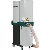
SPA 1702 W - Dust collector METABO - Free user manual and instructions
Find the device manual for free SPA 1702 W METABO in PDF.

| Product type | Dust collector |
| Brand | Metabo |
| Model | SPA 1702 W |
| Article code | 013 017 0100 |
| Motor power | 750 W |
| Voltage / Frequency | 230 V ~ 50 Hz |
| Nominal flow rate | 633 m³/h |
| Max flow rate | 1 010 m³/h |
| Guaranteed vacuum | 920 Pa |
| Max vacuum | 1 730 Pa |
| Nominal hose diameter | 100 mm |
| Chip bag volume | 90 L |
| Dimensions (L × W × H) | 882 × 562 × 1 671 mm |
| Weight | 24 kg |
| Sound level (EN 23744) | 81 dB(A) |
| Filter category | G |
| Intended use | Suction of wood chips from woodworking machines |
| Prohibited materials | Liquids, sharp objects, materials > 60°C |
| Assembly | To be assembled: frame, casters, wheels, suction unit, filter, bag, hose |
| Filter maintenance | Shake when off to dislodge fine dust |
| Bag replacement | After cleaning the filter, replace bag regularly |
| Monthly check | Filter condition, tightness, electrical equipment |
| Safety precautions | Disconnect before maintenance, wear a dust mask when replacing filter or bag |
| Original accessories | Recommended to ensure performance |
| Repair | Exclusively by qualified Metabo-approved personnel |
| Environmental protection | Recyclable packaging, device to be recycled at end of life |
Frequently Asked Questions - SPA 1702 W METABO
User questions about SPA 1702 W METABO
0 question about this device. Answer the ones you know or ask your own.
Ask a new question about this device
Download the instructions for your Dust collector in PDF format for free! Find your manual SPA 1702 W - METABO and take your electronic device back in hand. On this page are published all the documents necessary for the use of your device. SPA 1702 W by METABO.
USER MANUAL SPA 1702 W METABO
Vice President Product Engineering & Quality
Original operating instructions
Dear Customer,
Thank you for the trust you have placed in us by buying a metabo dust extractor. Every metabo machine is carefully tested and subjected to stringent quality control procedures by the metabo quality assurance department. Nevertheless, the service life of a machine depends to a great extent on you. Please read the information in these operating instructions and the accompanying documents. The greater the care with which you handle your metabo machine, the longer it will provide a reliable service to you.
Contents
Illustration: Parts Supplied (Page 3)
Illustration: Appliance Components (Page 4)
1 Mains Voltage / Order No.
2 Parts Supplied
3 Appliance Components
4 Safety Instructions
5 Proper Use
6 Assembly
6.1 Base
6.2 Castors and wheels
6.3 Suction unit
6.4 Filter, filter retaining clip and chip bag
6.5 Suction hose
7 Initial Use
8 Maintenance
9 Accessories
10 Repairs
11EnvironmentalProtection
12 Technical Specifications
1 Mains Voltage / Order No.
Before initial use, check that the mains voltage and mains frequency stated on the model plate match the figures for your own mains supply (refer to page 16).
2 Parts Supplied
1) Filter (Category "G")
2) Filter retaining clips
5) Filter clamping band
6) Suction unit
8) Hose clamp (2 pcs.)
9) Chip bag clamping band
10) 100mm suction hose, 2.5 m long
11) Chip bag
12)Connector
13) Castors (2 pce.)
14)Base-plate
15) 125mm wheels (2 pce.)
16)Column
18) Set of sundry assembly parts
19)OperatingInstructions
20) List of Spare Parts
Sundry parts (in bag):
M6x16 hexagonal socket-head screws 9 pce.
M8x60 hexagonal-head screws 2 pce.
M6 hexagonal nuts
M8 hexagonal nuts
6.4 washers
8.4 washers
12 pce.
3 Appliance Components
1) Filter
3) 750 watt electric motor
4) Combined switch/plug
5) Filter clamping band
6) Suction unit
8) Hose clamp
9) Chip bag clamping band
10) Suction hose
4 Safety Instructions

Read through these Operating Instructions carefully and thoroughly.
- The appliance must not be switched on until it has been completely assembled.
- Extractor should only be operated if the machine tools or cleaning nozzle are connected.
Solid bodies, e.g. pieces of wood (edge longer than 10mm ), metal scraps and stones etc. must not be vacuumed up. Materials of this kind cause damage to the fan impeller or the suction unit (rendering guarantee claims null and void). - Always disconnect the plug from the mains supply before undertaking any maintenance tasks, e.g. changing the bag, filter or hose, so as to exclude any possibility of injury caused by coming into contact with the moving fan impeller.
- Keep the appliance dry. Do not vacuum up any liquids.
- Do not use in any space where there is a risk of explosion.
- Always check that the appliance is operating properly before use.
-
Do not use the appliance at temperatures less than 0^ . Do not vacuum up any material which is at a temperature above 60^ .
-
The appliance must not be used by children or any person who is not familiar with its operation.
- Observe accident prevention and fire prevention regulations.
- When changing the filter (1) or the chip bag (11), a face-mask (filter-mask with particle filter, filter class 2) must be worn to provide protection from dust.
Before changing the chip bag (11), tap the filter (1) to dislodge deposits and clean. - Where accessories are to be used, these must be original manufacturer's parts only. The operator will render null and void any claims arising if he uses the chip extractor with anything other than original parts.
5 Proper Use

The chip extractor is designed for extracting wood chips with a low proportion of sawdust in connection with wood-processing machines (e.g. circular sawing machines, band sawing machines, surface planing and thickening machines and vertical spindle moulding machines) where these produce wood chips.
The appliance is not designed for vacuuming up liquids. In addition, it should not be used for the following materials: sharp-edged and pointed objects (such as broken glass or nails) or any material at a temperature above 60^ .
The operator bears sole responsibility for any damage caused by inappropriate use. The generally recognised accident prevention regulations and the "Safety Instructions" must be observed.
The chip extractor is designed for non-commercial use. Non-commercial use means that the appliance is not used by employees, persons undergoing professional training, in schools, for domestic purposes, or by persons in an employment relationship representing the equivalent of work.
6 Assembly
6.1 Base
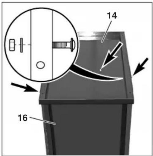
Set up the column (16) with the recess down. Position the base-plate (14) and secure with 5 M6x16 hexagonal socket-head screws, 6.4 washers and M6 hexagonal nuts as illustrated. To tighten threaded connections, use a 10mm AF box spanner and a 4mm AF Allen key for hexagonal socket-head screws.
6.2 Castors and wheels
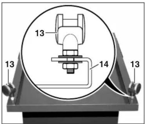
Locate 8.4 washer on the grub screw on the castor (13). Push castor (13) with its washer fitted into the holes drilled for the purpose in the base-plate (14).
Fit 8.4 washer and M8 hexagonal nut. Tighten hexagonal nut with a 13mm AF open-ended spanner while holding the castor in position with a second 13mm AF spanner.
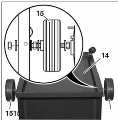
Fit wheel (15) with two 8.4 washers to the M8x60 hexagonal-head screw and tighten the M8 hexagonal nut so that the wheel (15) turns easily in its location between the washers on the hexagonal-head screw. Fit the 8.4 washer onto the hexagonal-head screws with the wheel (15) fitted in place. Insert the hexagonal-head screw through the lateral holes drilled in the base-plate (14) and secure with the 8.4 washer and M8 hexagonal nut. Press the cover into place on the wheel until it can be heard clicking into place (see illustration).
6.3 Suction unit
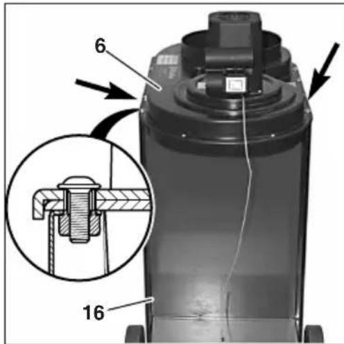
Locate the column (16) with base-plate on the wheels. Place the suction unit (6) on the column (16) and align. Insert 4 M6x16 hexagonal socket-head screws through the holes drilled for the purpose at the top and tighten with a 4 mm AF Allen key.
6.4 Filter, filter retaining clip and dust bag
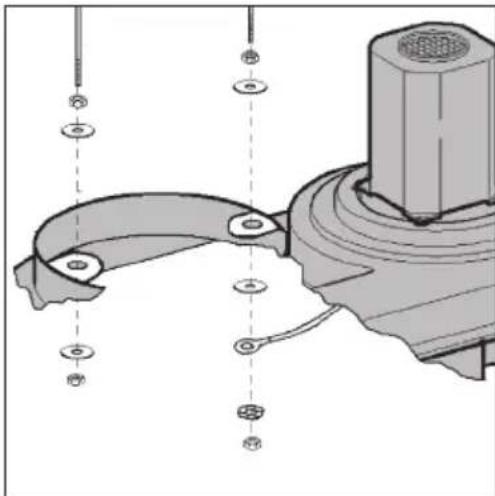
Screw M6 hexagon nuts into the filter retaining clip (2) halfway up the thread. Push on washers 6,4 and insert filter retaining clip (2) into the holes provided on the extractor (6).
Secure washer 6,4, stranded earth wire and serrated lock washer to the filter retaining clip (2) with M6 hexagon nuts, as shown in the illustration. Tighten M6 hexagon nuts.
Screw on washer 6,4 with M6 hexagon nut on the other side of the filter retaining clip (2) and tighten.
Push the filter (1) over the filter retaining clip (2). Push tension band over the filter (1). Push the filter (1) with tension band over the connector on the extractor assembly (6). Make sure that the filter (1) is over the extractor connector (6) all the way round and is positioned under the tension band. Secure the tension band with a screwdriver.
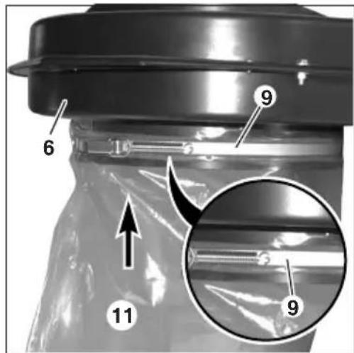
Push tension band (9) over the dust bag (11). Push tension band with bag over the connector on the underside of the extractor assembly (6). Make sure that the dust bag (11) is over the extractor connector (6) all the way round, and is positioned under the tension band. Align tension band so that it is positioned on the foam strip all the way round. Secure the tension band (9) by folding over the locking lever.
6.5 Suction hose
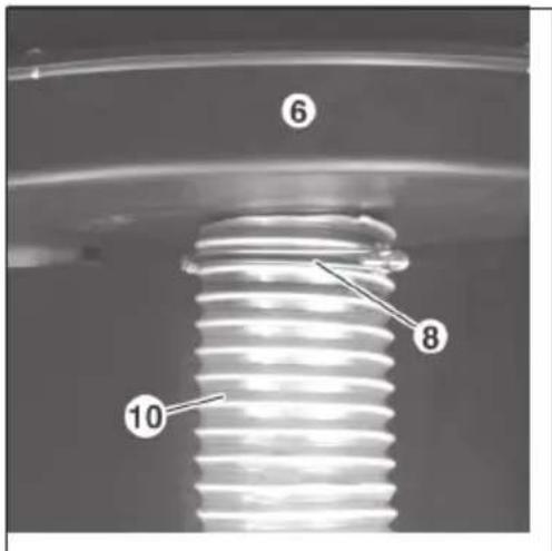
Push the hose clamp (8) over the suction hose (10). Push the suction hose (10) onto the small connector on the extractor assembly (6). Make sure that the suction hose (10) is positioned correctly all the way round. Secure the suction hose with the hose clamp (8).
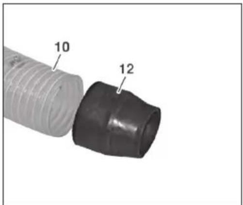
Push the connector (12) into the suction hose (10) and tighten the hose clamp to secure.
Push the suction hose (10) onto the extractor connection piece on the wood-processing machine.
7 Initial Use
For operation, the chip extractor re-quires a mains voltage of 230V 50Hz and a suitable extension cable with an earth conductor (three-core). The chip extractor may only be connected to sockets which have been earthed in compliance with regulations.
Before putting the chip extractor into use, the suction hose must be connected to the wood-processing machine as per instructions.
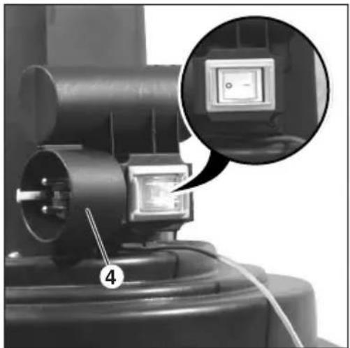
Fit the extension cable to the plug in the combined switch-plug fitting (4).
Switch in position Chip extractor
0 off
1 on
8 Maintenance
Always remove the plug from the mains socket before undertaking any maintenance task. If extraction performance drops off and before every chip bag change, the filter must be cleaned by tapping it by hand. This causes the fine sawdust which collects in the fabric of the filter (1) to fall into the chip back (11), thus allowing the filter (1) to remain free for the passage of air. The filter should be cleaned after every use, but without removing the filter. Only remove the chip bag once the dust has had time to settle and the fan impeller has come to a halt.
In addition, a monthly dust-test should be carried out by an appropriately instructed person to check:
for damage to the filter (1)
- that the housing is tight and that the seal for the chip bag (11) is intact
- that the electrical equipment is in good condition (combined switch-plug fitting (4), extension cable).
Under no circumstances may damaged filters (1) and chip bags (11) be returned to use.

Damaged parts, particularly safety devices, must only be replaced with genuine parts. Parts which have not been tested and released by the manufacturer can lead to unforeseen damage.
9 Accessories
metabo offers a wide range of accessories for the chip extractor. For this reason you should use only original metabo accessories to get the best out of your appliance. You will find an overview of accessories on page 4 and also in metabo's General Catalogue.
10 Repairs

Repairs to metabo power appliances must be carried out by a qualified electrician only.
Any metabo power appliances in need of repair can be sent to one of the addresses listed in the spare parts list. Please accompany the appliance for repair with a brief description of the fault identified. We reserve the right to make modifications in accordance with technical development.
11 Environmental Protection
metabo packaging is 100% recyclable. It should not be disposed of as domestic waste. This means that packaging can be fed back into the raw materials cycle.
Power appliances and accessories contain large amounts of valuable raw materials and plastics which can likewise be fed back into a recycling process. Accordingly, power appliances should not be disposed of as domestic waste, but should be channelled into an environmentally-friendly recycling process.
12 Technical Specifications
Chip Extractor SPA 1702
Order No. 0130170100
Power 750 watts
Voltage/frequency 230V 50Hz
Rated volumetric flow V_rat633~m^3 /h
Related vacuum 920 Pa
Max. volumetric flow V_ 1010 m^3/h
Max. vacuum 1730 Pa
Filter area 1.08 m
Filter (material) Category "G"
Nom. hose width 100 mm
Hose length 2.5 m
Chip bag volume 901
Noise as per
EN 23744 (acoustic
pressure level) 81 dB(A)
Dimensions
(LxWxH) 882×562×1671mm
Weight 24 kg
6.3 IbIeYdaIaIOoee yCTpoIcTBO
6.5 Bcacbbaiouyn uHaHr
7 BbOДВэкспунаТацию
8 TexHHueeckoe o6cnykUbaHne
9 PpinaJnEeKHOCTN
10 PeMoHT
11 3aunTa OkpykaOuSei cpebl
12 TexHnueckne xapaKTepeNCTUKN
1 CeteBoe HapjxHne / No 3aK.
Ipeed BBODOM B 3KcNpyaTuHIO npOBepbTe, COBnadaHT IIN yKa3aHHbIE Ha 3aBOdCKoT Ta6nue 3HaueHn HAnpJxKeHn N acToTbI cETn CnapaMeTpamn 3JIeKTpocetn (CM. CTp. 10).
2 06bem nocTaBkn
1) Φильър (kateropя "G")
2) Xomytnibtpa
5) CTeKHOXOMyTJnIaΦJIbTpTa
6) ΠbIeYdaIaIHOuIe ycTpoIcTBO
8) ⅢlaHroBb3axm(2wT.)
9) CTJXHON XOMYT JIЯ MeuKa JIЯ cTpYKIN
10) BcacbBaIoumI uHaHr 00 MM, dInHa 2,5 M
11) MewoK dIa cTpyKKn
12) CoeHHnteHbHn naTpbyok
13) HappaBraIouzni poNk (2 wT.)
14) Onopnna nnta
15) Koneco 0 125 MM (2 wT.)
16) CToiKa
18) KomnneKT MeIKNX DeTaneN JIa MOHTaKa
19)PykoBOdCTBO NO MOHTaXy
20) Cnncok 3anaChbix yacTei
MeIknne Detannn (B nakete):
BnHT C BHyTpEHHIM
WecTnRpahHnKOM M6x16 9 wt.
BnHTcIeCTnIgpaHHoH
roJIOBkoM8x60 2uT.
Jecnturpanna raika M6 9 tT.
JecntnnpaHraKaM8 6 wt.
7a#6a 6,4 9 wt.
7a#6a 8,4 12 wt.
3 ΘЯ�мьустpoиctBa
1) ΦπbTp
3) ΘneKtpoDbBnraTeNb 750 B
4) KomboHaiznBbIKHouaTeNb/TeKepe
5) CTJHHoXOMyTdIJIaΦJIbTpA
6) ΠbIeYdaJIaIIOuIe yCTpoIcTBO
8) ⅢaHaHroBbI 3axIM
9) CTaXHOn XOMyT dIЯ MeuKa dIЯ cTpYKKn
10) BcabBaIOuI MlaHr
11) MeowokdIa ctpyKk
CpOK cnJyH6bl HnCTpyMeHTa: 5 JeT C daTbI n3rTOBJIeHn
Metabowerke GmbH
Metabo-Allee 1
72622 Nuertingen
Germany
www.metabo.com