SBE 521 - Drill METABO - Free user manual and instructions
Find the device manual for free SBE 521 METABO in PDF.
User questions about SBE 521 METABO
0 question about this device. Answer the ones you know or ask your own.
Ask a new question about this device
Download the instructions for your Drill in PDF format for free! Find your manual SBE 521 - METABO and take your electronic device back in hand. On this page are published all the documents necessary for the use of your device. SBE 521 by METABO.
USER MANUAL SBE 521 METABO
GRIP, ZU AUF, RELEASE
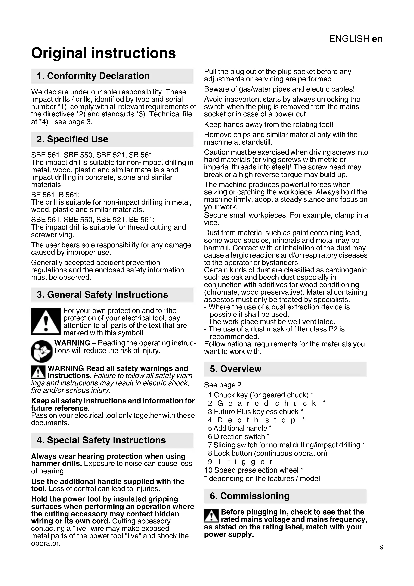
Original instructions We declare under our sole responsibility: These impact drills / drills, identified by type and serial number *1), comply with all relevant requirements of the directives *2) and standards *3). Technical file at *4) - see page 3. SBE 561, SBE 550, SBE 521, SB 561: The impact drill is suitable for non-impact drilling in metal, wood, plastic and similar materials and impact drilling in concrete, stone and similar materials. BE 561, B 561: The drill is suitable for non-impact drilling in metal, wood, plastic and similar materials. SBE 561, SBE 550, SBE 521, BE 561: The impact drill is suitable for thread cutting and screwdriving. The user bears sole responsibility for any damage caused by improper use. Generally accepted accident prevention regulations and the enclosed safety information must be observed. For your own protection and for the protection of your electrical tool, pay attention to all parts of the text that are marked with this symbol! WARNING – Reading the operating instruc- tions will reduce the risk of injury. WARNING Read all safety warnings and instructions. Failure to follow all safety warn- ings and instructions may result in electric shock, fire and/or serious injury. Keep all safety instructions and information for future reference. Pass on your electrical tool only together with these documents. Always wear hearing protection when using hammer drills. Exposure to noise can cause loss of hearing. Use the additional handle supplied with the tool. Loss of control can lead to injuries. Hold the power tool by insulated gripping surfaces when performing an operation where the cutting accessory may contact hidden wiring or its own cord. Cutting accessory contacting a "live" wire may make exposed metal parts of the power tool "live" and shock the operator. Pull the plug out of the plug socket before any adjustments or servicing are performed. Beware of gas/water pipes and electric cables! Avoid inadvertent starts by always unlocking the switch when the plug is removed from the mains socket or in case of a power cut. Keep hands away from the rotating tool! Remove chips and similar material only with the machine at standstill. Caution must be exercised when driving screws into hard materials (driving screws with metric or imperial threads into steel)! The screw head may break or a high reverse torque may build up. The machine produces powerful forces when seizing or catching the workpiece. Always hold the machine firmly, adopt a steady stance and focus on your work. Secure small workpieces. For example, clamp in a vice. Dust from material such as paint containing lead, some wood species, minerals and metal may be harmful. Contact with or inhalation of the dust may cause allergic reactions and/or respiratory diseases to the operator or bystanders. Certain kinds of dust are classified as carcinogenic such as oak and beech dust especially in conjunction with additives for wood conditioning (chromate, wood preservative). Material containing asbestos must only be treated by specialists. - Where the use of a dust extraction device is possible it shall be used. - The work place must be well ventilated. - The use of a dust mask of filter class P2 is recommended. Follow national requirements for the materials you want to work with. See page 2. 1 Chuck key (for geared chuck) * 2Geared chuck * 3 Futuro Plus keyless chuck * 4Depth stop * 5 Additional handle * 6 Direction switch * 7 Sliding switch for normal drilling/impact drilling * 8 Lock button (continuous operation) 9Trigger 10 Speed preselection wheel *
- depending on the features / model Before plugging in, check to see that the rated mains voltage and mains frequency, as stated on the rating label, match with your power supply.
3. General Safety Instructions
4. Special Safety Instructions
6. CommissioningENGLISHen
SBE 561, SBE 550, SBE 521, BE 561: Make sure the chuck clamps securely: After drilling for the first time (clockwise), firmly tighten the safety screw inside the chuck using a screwdriver. Caution: left-handed thread! (see Section 7.8)
6.1 Attaching the Additional Handle
(SBE 561, SBE 550, SBE 521, SB 561) For safety reasons, always use the additional handle supplied. Open the clamping ring by turning the additional handle (5) anticlockwise. Push the additional handle onto the collar of the machine. Insert the depth stop (4). Securely tighten the additional handle at the angle required for the application.
7.1 Adjusting the Depth Stop
(SBE 561, SBE 550, SBE 521, SB 561) Loosen the additional handle (5). Set depth stop (4) to the desired drilling depth and retighten additional handle.
7.2 Switching On and Off
To start the machine, press the trigger switch (9). SBE 561, SBE 550, SBE 521, BE 561: Press in the trigger switch to change the speed. For continuous operation the trigger switch can be locked using the lock button (8). To stop the machine, press the trigger switch again. In continuous operation, the machine continues running if it is forced out of your hands. Therefore, always hold the machine with both hands using the handles provided, stand in a safe position and concentrate.
7.3 Speed Preselection
(SBE 561, SBE 550, SBE 521, BE 561) Select the (10) maximum speed using the preselection wheel. See page 4 for recommended drilling speeds.
7.4 Switching Between Normal Drilling/
Impact Drilling (SBE 561, SBE 550, SBE 521, SB 561) Select the desired operating mode by pushing the sliding switch (7). Drilling Impact drilling Work with high speed settings when impact drilling. Impact drilling and normal drilling only in a clockwise direction.
7.5 Selecting the Direction of Rotation
(SBE 561, SBE 550, SBE 521, BE 561) Do not activate the direction switch (6) unless the motor has completely stopped. Select direction of rotation: R=Clockwise L=Anticlockwise Screw the chuck firmly to the spindle and tighten the safety screw inside the chuck using a screwdriver. (Caution: left-handed thread!) Otherwise it may come loose during anticlockwise operation (e.g. when screwdriving).
7.6 Tool Change With
Futuro Plus Keyless Chuck (3) Machines with the designation SB...: See illustrations on page 2. Insert the tool. Hold the retaining ring (a) firmly and turn the collet (b) towards "GRIP, ZU" with the other hand until the mechanical resistance which can be felt is overcome. Caution! The tool is not yet clamped! Keep turning the sleeve (it must "click" when turning) until it cannot be turned any further - only now is the tool securely clamped. With a soft tool shank, retightening may be required after a short drilling period. Open the chuck: Hold the retaining ring (a) firmly and turn the collet (b) towards "AUF, RELEASE" with the other hand. Note: The grating sound which may be heard after opening the drill chuck is functional and is stopped by turning the sleeve in the opposite direction. If the chuck is very securely tightened: Unplug. Hold the drill chuck using an open-end spanner at the flats on its head, and turn the sleeve (b) vigourously in the direction of "AUF, RELEASE". Machines with the designation B...: See illustrations on page 2. Insert the tool. Hold the retaining ring (a) firmly and turn the collet (b) towards "GRIP, ZU" with the other hand until it will not turn any further. With a soft tool shank, retightening may be required after a short drilling period. Open the chuck: Hold the retaining ring (a) firmly and turn the collet (b) towards "AUF, RELEASE" with the other hand. If the chuck is very securely tightened: Unplug. Hold the drill chuck using an open-end spanner at the flats on its head, and turn the sleeve (b) vigourously in the direction of "AUF, RELEASE".
7.7 Tool Change With
Geared Chuck (2) See illustrations on page 2. Clamping tools: Insert the tool and clamp evenly in all 3 holes using the chuck key (1). Removing tools: Open the geared chuck (2) using the chuck key (1) and remove the tool.
7.8 Removing the Chuck
SBE 561, SBE 550, SBE 521, BE 561: The chuck can be removed to insert a screwdriver bit. Insert the bit directly in the hexagon socket on the spindle.
The screwdriver bit is retained if a bit clamping bush (as an accessory: order no. 6.31281) is fitted. Futuro Plus keyless chuck See page 4, illustration A. Unscrew the safety screw - if available. Caution: left-handed thread! Hold the drill spindle securely using an open-end wrench. Clamp an Allen key in the chuck and strike lightly with a rubber hammer to loosen, then unscrew. Geared chuck See page 4, illustration B. Unscrew the safety screw - if available. Caution: left-handed thread! Hold the drill spindle securely using an open-end wrench. Insert the key in the chuck and strike lightly with a rubber hammer to loosen, then unscrew. Keyless chuck cleaning: After prolonged use hold the chuck vertically, with the opening facing down, and fully open and close it several times. The dust collected falls from the opening. Regular use of cleaning spray on the jaws and jaw openings is recommended.
Use only genuine Metabo accessories. Use only accessories which fulfil the requirements and specifications listed in these operating instruc- tions. Fit accessories securely. Secure the machine if it is operated in a bracket. Loss of control can cause personal injury. For a complete range of accessories, see www.metabo.com or the main catalogue. Repairs to electrical tools must be carried out by qualified electricians ONLY! Contact your local Metabo representative if you have Metabo power tools requiring repairs. For addresses see www.metabo.com. You can download a list of spare parts from www.metabo.com. Observe national regulations on environmentally compatible disposal and on the recycling of disused machines, packaging and accessories. Only for EU countries: Never dispose of power tools in your household waste! In accordance with European Guideline 2002/ 96/EC on used electronic and electric equipment and its implementation in national legal systems, used power tools must be collected separately and handed in for environmentally compatible recycling. Explanatory notes on the specifications on page 3. Changes due to technological progress reserved.
=Speed at rated load ø max =Max. solid drill diameter s max =Max. impact rate G =Drill spindle thread H =Drill spindle with hexagon socket m =Weight without mains cable D =Collar diameter Measured values determined in conformity with EN 60745. Machine in protection class II ~ Alternating current The technical specifications quoted are subject to tolerances (in compliance with the relevant valid standards). Emission values Using these values, you can estimate the emis- sions from this power tool and compare these with the values emitted by other power tools. The actual values may be higher or lower, depending on the particular application and the condition of the tool or power tool. In estimating the values, you should also include work breaks and periods of low use. Based on the estimated emission values, specify protective measures for the user - for example, any organisa- tional steps that must be put in place. Vibration total value (vector sum of three directions) determined in accordance with EN 60745:
h, ID =Vibration emission value (impact drilling into concrete)
h, D =Vibration emission value (drilling into metal)
h,D =Uncertainty (vibration) Typical A-effective perceived sound levels:
=Sound pressure level
=Acoustic power level
= Uncertainty During operation the noise level can exceed 80 dB(A). Wear ear protectors!
h, D =trillingsemissiewaarde (boren in metaal)
h, D =Vibrationsemissionsvärde (borrning i metall)
h, D =Vibrationsemission (boring i metal)