1987681 - Multifunction tool MAKITA - Free user manual and instructions
Find the device manual for free 1987681 MAKITA in PDF.
| Product Type | Brushcutter attachment for motorized unit |
| Models | EM403MP, EM404MP, EM405MP, EM406MP |
| Dimensions (L × W × H) | 876 mm × 392 mm × 225 mm (EM403MP/EM404MP) ; 876 mm × 187 mm × 232 mm (EM405MP/EM406MP) |
| Net weight | 1.3 kg to 1.5 kg depending on model |
| Cutting diameter (nylon line head) | 420 mm |
| Cutting diameter (plastic blade) | 255 mm |
| Cutting diameter (metal blade) | 230 mm (EM403MP/EM404MP only) |
| Nylon line diameter | 2.0 to 2.4 mm |
| Gear ratio | 14:19 (EM403MP/EM405MP) or 13:21 (EM404MP/EM406MP) |
| Approved power units | EX2650LH (petrol) ; DUX60, UX01G (cordless) |
| Compatible cutting tools | Nylon line head, plastic blade, metal blade (depending on model) |
| Guards | Universal type (EM403MP/EM404MP) or narrow type (EM405MP/EM406MP) |
| Safety | Mandatory wearing of gloves, goggles, helmet, safety shoes; safety distance of 15 m |
| Maintenance – Lubrication | Gear case and motor shaft every 30 service hours |
| Maintenance – Cleaning | Visual inspection before each use; tighten screws |
| Repairability | Makita spare parts; repair by authorized center |
Frequently Asked Questions - 1987681 MAKITA
User questions about 1987681 MAKITA
0 question about this device. Answer the ones you know or ask your own.
Ask a new question about this device
Download the instructions for your Multifunction tool in PDF format for free! Find your manual 1987681 - MAKITA and take your electronic device back in hand. On this page are published all the documents necessary for the use of your device. 1987681 by MAKITA.
USER MANUAL 1987681 MAKITA
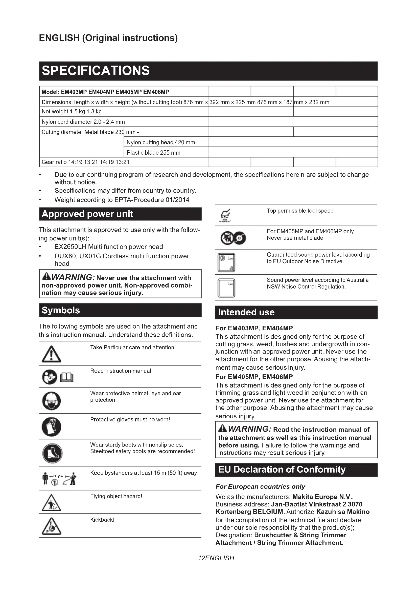
Due to our continuing program of research and development, the specifications herein are subject to change without notice.
Specifications may differ from country to country.
Weight according to EPTA-Procedure 01/2014
Approved power unit
This attachment is approved to use only with the following power unit(s):
EX2650LH Multi function power head
DUX60, UX01G Cordless multi function power head
WARNING: Never use the attachment with non-approved power unit. Non-approved combination may cause serious injury.
Symbols
The following symbols are used on the attachment and this instruction manual. Understand these definitions.

Take Particular care and attention!

Read instruction manual.

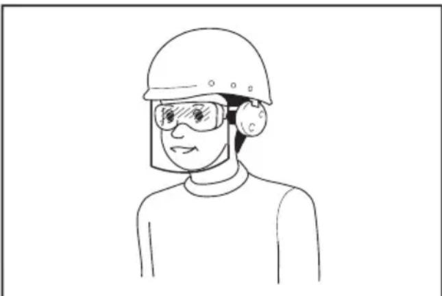
Wear protective helmet, eye and ear protection!

Protective gloves must be worn!

Wear sturdy boots with nonslip soles. Steeltoed safety boots are recommended!

Keep bystanders at least 15m (50 ft) away.

Flying object hazard!

Kickback!

Top permissible tool speed

For EM405MP and EM406MP only Never use metal blade.

Guaranteed sound power level according to EU Outdoor Noise Directive.

Sound power level according to Australia NSW Noise Control Regulation.
Intended use
For EM403MP, EM404MP
This attachment is designed only for the purpose of cutting grass, weed, bushes and undergrowth in conjunction with an approved power unit. Never use the attachment for the other purpose. Abusing the attachment may cause serious injury.
For EM405MP, EM406MP
This attachment is designed only for the purpose of trimming grass and light weed in conjunction with an approved power unit. Never use the attachment for the other purpose. Abusing the attachment may cause serious injury.

WARNING: Read the instruction manual of the attachment as well as this instruction manual before using. Failure to follow the warnings and instructions may result serious injury.
EU Declaration of Conformity
For European countries only
We as the manufacturers: Makita Europe N.V., Business address: Jan-Baptist Vinkstraat 2 3070 Kortenberg BELGIUM. Authorized Kazuhisa Makino
for the compilation of the technical file and declare under our sole responsibility that the product(s);
Designation: Brushcutter & String Trimmer
Attachment / String Trimmer Attachment.
Designation of Type(s): EM404MP / EM406MP. Fulfills all the relevant provisions of 2006/42/EC and also fulfills all the relevant provisions of the following EC/EU Directives: 2000/14/EC and are manufactured in accordance with the following Harmonised Standards: EN 60335-1:2012+A11:2014+A13:2017+A1:2019+A14:2019+A2:2019+A15:2021 (EM406MP), EN 62841-1:2015+A11:2022 (EM404MP), EN 50636-2-91:2014 (EM406MP), EN ISO 11806-1:2022 (EM404MP).
Place and date of declaration: Kortenberg, Belgium. 1.8.2024
Responsible person: Kazuhisa Makino, Director - Makita Europe N.V.

Declaration of Conformity (For UK)
For UK only
We as the manufacturers: Makita Europe N.V., Business address: Jan-Baptist Vinkstraat 2 3070 Kortenberg BELGIUM. Authorized Kazuhisa Makino for the compilation of the technical file and declare under our sole responsibility that the product(s);
Designation: Brushcutter & String Trimmer
Attachment, String Trimmer Attachment. Designation of Type(s): EM404MP / EM406MP.
Fulfills all the relevant provisions of S.I. 2008/1597 (as amended) and also fulfills all the relevant provisions of the following UK Regulations: S.I. 2001/1701 (as amended) and are manufactured in accordance with the following Designated Standards: EN 60335-1:2012+A11:2014+A13:2017+A1:2019+A14 :2019+A2:2019+A15:2021 (EM406MP), EN 62841-1:2015+A11:2022 (EM404MP), EN 50636-2-91:2014 (EM406MP), EN ISO 11806-1:2022 (EM404MP).
Place and date of declaration: Kortenberg, Belgium. 1.8.2024
Responsible person: Kazuhisa Makino, Director - Makita Europe N.V.
Importer: Makita (UK) Limited, Michigan Drive,
Tongwell, Milton Keynes, Buckinghamshire, MK15 8JD, UK

SAFETYWARNINGS
Brushcutter safety warnings
WARNING: Read all safety warnings, instructions, illustrations and specifications provided with this machine. Failure to follow all instructions listed below may result in fire and/or serious injury to the operator and/or bystanders.
Save all warnings and instructions for future reference.
The term "brushcutter" and "machine" in the warnings and precautions refer to the combination of the attachment and the power unit.
The term "motor" in the warnings and precautions refers to the engine or electric motor of the power unit.
General safety
- First-time or inexperienced operator should ask the dealer for training in all operation of the machine. Never allow children, persons with reduced physical, sensory or mental capabilities or lack of experience and knowledge or people unfamiliar with the instructions to use the machine.
- It is recommended only to lend the machine to people who have proven to be experienced. Always hand over the instruction manual.
- Stay alert, watch what you are doing and use common sense when operating the machine. Do not use the machine while you are tired, ill, or under the influence of drugs, alcohol or medication. A moment of inattention while operating the machine may result in serious personal injury.
- Avoid using the machine in bad weather conditions especially when there is a risk of lightning.
- Follow your national and local regulation for use of outdoor power machines.
Intended use of machine
This machine is only intended for cutting grass, weeds, bushes and undergrowth. Never use the machine for any other purpose such as edging or hedge cutting. Use for unintended purpose may result in serious injury.
Personal protective equipment
- Always wear heavy, long pants, sturdy boots, gloves, and a long-sleeve shirt. Do not wear loose clothing, jewelry, short pants, sandals, or go barefoot. Secure hair so it is above shoulder level.
- Always wear a helmet where there is a risk of falling objects.
- Always wear protective goggles to protect your eyes from injury when using the machine. The goggles must comply with ANSI Z87.1 in the USA, EN 166 in Europe, or AS/NZS 1336 in Australia/New Zealand. In Australia/New Zealand, it is legally required to wear a face shield to protect your face, too.
It is an employer's responsibility to enforce
the use of appropriate safety protective equipments by the tool operators and by other persons in the immediate working area.
- Wear ear protection, such as ear muffs. Exposure to noise can cause hearing loss
- Always wear sturdy shoes with a non-slip sole. This protects your feet against injuries and ensures a good footing.
- Wear a dust mask as necessary.
Preparation before use
-
Before use, always check the machine is safe for operation:
-
Check for fuel leaks.
Make sure all fasteners are in place and secure. - Replace damaged parts.
Make sure the cutting tool is properly installed and securely fastened.
Make sure the cutting tool guard is properly attached in the position as described in this manual. - Check the throttle trigger, lock-off lever and other control switch for smooth action and proper function.
Clean the handles for proper control of the machine.
Make sure the handles are installed as described in this manual.
Failure to follow those instructions may cause serious injury.
- Use a sharp blade. Discard blades that are bent, warped, cracked, broken, chipped or damaged in any way. A dull blade is more likely to snag and kickback.
- Always use all required parts for fixing the blade properly. Improper fixing parts can cause the blade to fly off and seriously injure the operator and/or bystanders.
Refueling
- Stop the engine before refueling. Keep away from open flames and sparks. Never smoke during refueling. Otherwise fire and/or explosion may result.
- Refuel outdoors. Refueling in a closed room can cause explosion of fuel vapor.
- Avoid contact with fuel or engine oil. Do not inhale fuel vapor. If fuel or oil spills, wipe it off from the machine and/or ground immediately. If fuel spills on your clothes, change it immediately to prevent it from catching fire.
- After refueling, carefully tighten the fuel tank cap and check for fuel leak. Move at least 3m (10 feet) away from the fueling source and site before starting engine.
- Only transport and store fuel in approved containers. Keep children away from the stored fuel.
Starting up the brushcutter
- Keep children, bystanders and pets at least 15 m (50 feet) away, when starting up or using the
machine. Additionally, bystanders should wear eye protection, as there is still a risk of injury from thrown objects. Otherwise bystanders' unexpected action or blade kickback may cause serious injury to the operator and/or bystanders.
- Start and operate the machine only outdoors in a well ventilated area. Operation in a confined or poorly ventilated area can result in death due to suffocation or carbon monoxide poisoning.
- Before starting, make sure that the cutting tool has no contact with hard objects such as branches, stones etc. as the cutting tool will revolve when starting.
- If the cutting tool rotates at idle, adjust the idle speed so that it stops at idle. Otherwise unintentional contact with moving cutting tool may result in serious injury.
- Stop the motor immediately if you notice any trouble.
Transportation
- Stop the motor during transport. Otherwise unintentional start-up may cause injury.
- When transporting the machine, always attach the cover to the cutting blade. Contact with bare blades results in injury.
- Ensure safe position of the machine during car transportation to avoid fuel leakage.
- Lift the entire machine from the ground when carrying the machine. Dragging the machine causes fuel tank damage and fuel leakage, resulting in fire.
Operation
- Only use the machine in good light and visibility. Use in the dark or poor visibility area may cause unexpected accident.
- Avoid using the machine when it is hard to keep your balance, for example, working on a steep surface or windy day.
- During the winter season, beware of slippery or wet areas, ice and snow to avoid slipping.
- If you are approached, stop the motor. Otherwise the rotating cutting tool may hit the bystander and result in serious injury.
-
Clear the working area before operation. Remove all objects such as rocks, broken glass, nails, wire, or string, which can be thrown or become entangled in the cutting attachment. Foreign particles may damage the cutting tool and can cause dangerous kickback.
-
To control the machine steadily, do the following during operation:
Hold the machine with both hands firmly on your right side.
Hang the machine on your shoulder(s) with the shoulder harness.
- Ensure a safe footing. Never work on a ladder or in a tree.
Avoid over-reach.
- Keep cutting tool below waist level.
- Keep all parts of your body away from the rotating cutting tool and hot surface.
Those actions reduce the risk of injury.
- If weeds or branches get caught between the cutting tool and guard, always stop the motor before clearing. Otherwise unintentional blade rotation may cause serious injury.
- Never drop or throw the machine, unless an emergency. If the machine drops or hits something, immediately check for fuel leakage, safety devices and other damages. Operating a malfunctioned machine may cause injury and/or fire.
- Inspect the cutting tool frequently, or immediately after it hits a stone or other hard objects. If the cutting tool breaks during operation, the broken piece may fly and cause injury.
- Stop the motor when inspecting, cleaning or replacing the cutting tool. Otherwise the cutting tool may rotate unexpectedly and result in serious injury.
- Maintain proper control until the cutting tool stops completely, when stopping the motor or releasing the throttle trigger. A coasting blade can cause injury.
- Before starting the cutting operation, wait until the cutting tool attains enough speed for cutting. It reduces the risk of kickback and entangling weeds.
- Take a rest to prevent loss of control caused by fatigue. We recommend taking a 10 to 20-minute rest every hour.
- Stop the motor and place it in safe location, when resting or leaving the machine. It prevents unexpected accident.
- Do not touch the engine and its muffler or do not put them onto combustible materials, while the engine runs or just after stopping it, as they are hot. Burn and/or fire may result.
Cutting Tools
- Use a suitable cutting tool for your work.
Nylon cutting heads (string trimmer heads) are suitable for trimming lawn grass.
Metal blades are suitable for cutting weeds, high grasses, bushes, shrubs, underwood, thicket, and the like.
Always use the cutting tool guard properly suited for the cutting tool used.
- When using a nylon cutting head, use only flexible, nonmetallic line recommended in this manual. Never use wire or wirerope. They can break off and become a dangerous projectile.
- Never use metal multi-piece pivoting chains, flail blades or blades not recommended in this manual. Otherwise serious injury may result.
- When handling the metal blade, always wear gloves and put the blade cover on the blade. The blade can cut bare hands.
- When using metal blades, avoid "kickback" and always prepare for an accidental kickback. See the section Kickback.
Kickback (blade thrust)
Kickback (blade thrust) may occur when the spinning blade contacts an object that it does not
immediately cut. It can be violent enough to cause the unit and/or operator to be propelled in any direction, and possibly lose control of the unit, resulting in serious injury. Kickback can occur without warning if the blade snags, stalls or binds and is more likely to occur in areas where it is difficult to see the material being cut.
Kickback occurs particularly when applying the blade segment between 12 and 2 o'clock to solids, bushes and trees with 3cm or larger diameter.
Fig.1
To avoid kickback:
- Apply the segment between 8 and 11 o'clock.
- Swing the tool evenly in half-circle from right to left, like using a scythe. This allows the proper segment of blade to contact plants to be cut.
- Never apply the segment between 12 and 2 o'clock.
- Never apply the segment between 11 and 12 o'clock and between 2 and 5 o'clock, unless the operator is well trained and experienced and does it at his/her own risk.
Fig.2
- Never use cutting blades close to solids, such as fences, walls, tree trunks and stones.
- Never use cutting blades vertically, for such operations as edging and trimming hedges.
- Avoid using the tool in areas where it is difficult to see the object being cut.
Vibration
Exposing to excessive vibration injures blood vessels or nervous system of the operator and causes the following symptoms in the fingers, hands or wrists: "Falling asleep" (numbness), tingling, pain, stabbing sensation, or alteration of skin color or of the skin. If any of these symptoms occur, see a physician.
To reduce the risk of "white finger disease", keep your hands warm during operation and well maintain the machine and accessories.
Maintenance
- Have your machine serviced by our authorized service center using only identical replacement parts. Use only identical spare parts and accessories supplied by MAKITA. Incorrect repair and poor maintenance can shorten the life of the machine and increase the risk of accidents.
- Never alter or remove any components of the machine. It may cause fire and/or serious injury.
- After use, clean the machine and check all screws and nuts for tightness.
- Check the condition of the cutting tool, cutting tool guard and shoulder harness. The cutting blade must be sharp. Never straighten or weld damaged cutting tools.
Other instructions
-
Always store the machine in locked rooms and with an emptied fuel tank.
-
Pay attention to the environment. Avoid unnecessary throttle operation for less pollution and noise emissions. Adjust the carburetor correctly.
- Do not operate the engine with faulty exhaust muffler.
First Aid
- In case of accident make sure that a first-aid box is available in the vicinity of the cutting operations. Immediately replace any item taken from the first aid box.
-
When asking for help, give the following information:
-
Place of accident
- What happened
Number of injured persons
Kind of injuries
— Your name
Additional safety instructions
- To avoid accident, leave more than 15m (50 ft) distance between operators when two or more operators work in one area. Also, arrange a person to observe the distance between operators. If someone or an animal enter the working area, immediately stop the operation.
- Only use the cutting tools that are marked with a speed equal or higher than the speed marked on the tool.
- Be sure to remove the cover on the cutting blade before operation.
PARTS DESCRIPTION
EM403MP, EM404MP
Fig.3: 1. Cap 2. Pipe 3. Protector (universal type) 4. Protector extension 5. Cutter
EM405MP, EM406MP
Fig.4: 1. Cap 2. Pipe 3. Protector (narrow type) 4.Cutter
ASSEMBLY
WARNING: Before assembling or adjusting the equipment, switch off the motor and remove the spark plug cap or battery cartridge. Otherwise the cutting tool or other parts may move and result in serious injury.
WARNING: Before handling cutting blade, wear protective gloves. During the assembly or adjustment, your fingers may contact with the cutting blade and it may cause serious injury.
WARNING: When assembling or adjusting the equipment, always put it down. Assembling or adjusting the equipment in an upright position may result in serious injury.
WARNING: Follow the warnings and precautions in the chapter "SAFETY WARNINGS" and the instruction manual of the power unit.
Correct combination of the cutting tool and the protector
CAUTION: Always use the correct combination of cutting tool and protector. The wrong protector may not protect you from flying debris and stones. It can also affect the balance of the tool and result in serious personal injury.
| Model Cutting tool Protector | ||
| EM403MP EM404MP | Metal blade (with nut, cup, and clamp washer) | Protector (universal type) |
| Nylon cutting head / Plastic blade Protector | (universal type) with protector extension | |
| EM405MP EM406MP | Nylon cutting head / Plastic blade Protector | (narrow type) |
Installing the protector (cutting tool guard)
WARNING: Do not use a cutting tool without an appropriate protector at any time.
WARNING: Always use the cutting tool with the correct combination of the protector. Otherwise contact with a cutting tool may cause serious injury.
NOTICE: Periodically tighten the bolts on the protector. Tighten the right and left bolts evenly so that the gap between the clamp and the protector is constant.
Fix the protector to the clamp with bolts.
Protector (universal type)
Fig.5: 1.Clamp 2. Protector
Protector (narrow type)
Fig.6: 1.Clamp 2. Protector 3.Cutter
CAUTION: Be careful not to injure yourself with the cutter mounted on the protector.
NOTE: The cutter on the protector keeps the nylon cord best length for cutting.
For EM403MP and EM404MP
To install the protector extension, insert the protector extension to the protector and then snap the clips on. Make sure that the tabs on the protector extension fit into the slots on the protector.
▶ Fig.7: 1. Protector (universal type) 2. Clip 3. Protector extension 4. Cutter (inside) 5. Slot 6. Tab
To remove the protector extension from the protector, unclasp the clips and pull the protector extension out.
CAUTION: Make sure to push in the protector extension until it is fully inserted. Otherwise the protector extension may fall and result in personal injury.
CAUTION: Be careful not to injure yourself with the cutter mounted on the protector extension.
NOTE: The cutter on the protector extension keeps the nylon cord best length for cutting.
Installing the cutting tool
CAUTION: Be sure to use genuine MAKITA cutting tools.
CAUTION: Be sure to remove the hex wrench after installation.
NOTE: When installing the cutting tool, turn the tool upside down for ease of the procedure.
Installing the metal blade
For EM403MP and EM404MP
CAUTION: When handling the metal blade, always wear gloves and put the blade cover on the blade.
CAUTION: The outside diameter of the metal blade must be 230~mm (9"). Never use any blades larger than 230~mm (9") in outside diameter.
CAUTION: The metal blade must be well polished, free of cracks or breakage. If the metal blade hits against a stone during operation, stop the motor and check the blade immediately.
CAUTION: Polish or replace the metal blade every three hours of operation.
CAUTION: Always use the supplied wrench(es) to remove or to install the blade.
Applicable blade
Metal blade (2-tooth)

Metal blade (3-tooth)

Metal blade (4-tooth)

Metal blade (4-tooth)

Metal blade (8-tooth)
- Insert the receive washer into the shaft.
- Insert the hex wrench through the hole in the gear case to lock the shaft. Rotate the shaft until the hex wrench is fully inserted.
- Mount the metal blade onto the receive washer.
- Install the clamp washer and cup, and then tighten the nut securely. Tightening torque: 16 - 23 N·m
- Remove the hex wrench.
▶ Fig.8: 1. Nut 2. Cup 3. Clamp washer 4. Metal blade 5. Receive washer 6. Shaft 7. Hex wrench
Fig.9: 1. Socket wrench 2. Hex wrench 3. Tighten
Make sure that the arrows on the blade and protector indicate the same way.
Fig.10
To remove the metal blade, follow the installation procedure in reverse.
NOTE: The resin part on the blade fastening nut wears out in course of time. Replace the nut if there appears any wear or deformation.
Installing the nylon cutting head
CAUTION: If the nylon cutting head hits against a stone during operation, stop the motor and check the nylon cutting head immediately.
- Put the receive washer on the shaft.
- Insert the hex wrench through the hole in the gear case.
- Screw the nylon cutting head onto the shaft.
- After installing nylon cutting head, remove the hex wrench.
Fig.11: 1. Nylon cutting head 2. Receive washer 3. Shaft 4. Hex wrench 5. Tighten
Installing plastic blade
Optional accessory
CAUTION: If the plastic blade accidentally impacts a rock or hard object during operation, stop the tool and inspect for any damage. If the plastic blade is damaged, replace it immediately. Use of a damaged cutting tool could result in serious personal injury.
CAUTION: Be sure to remove the hex wrench after installation.
NOTICE: Be sure to use genuine Makita plastic blade.
Fig.12: 1. Plastic blade 2. Receive washer 3. Shaft 4. Hex wrench 5. Tighten
- Put the receive washer on the shaft.
- Insert the hex wrench through the hole on the gear case and rotate the spindle until the spindle is locked.
- Place the plastic blade onto the threaded spindle directly and tighten.
- Remove the hex wrench.
To remove the plastic blade, turn it clockwise while holding the receive washer with the hex wrench.
Mounting the attachment pipe
CAUTION: Always check that the attachment pipe is secured after installation. Improper installation may cause the attachment falling off from the power unit and cause personal injury.
Mount the attachment pipe to the power unit.
- Turn the lever of the power unit toward the attachment side.
Fig.13: 1.Lever - Remove the cap of the attachment. Align the pin with the arrow mark and insert the attachment pipe until the release button pops up.
Fig.14: 1. Release button 2. Arrow mark 3. Pin - Turn the lever toward the power unit side.
Fig.15: 1.Lever
Make sure that the surface of the lever is parallel to the pipe.
To remove the pipe, turn the lever toward the attachment side and pull the pipe out while pressing down the release button.
Fig.16: 1. Release button 2. Lever 3. Pipe
OPERATION
WARNING: Follow the warnings and precautions in the chapter "SAFETY WARNINGS" and the instruction manual of the power unit.
WARNING: If the cutting tool moves at idle, adjust the idle speed of the engine down. Otherwise you cannot stop the cutting tool by throttle off and it may cause serious injury.
Adjusting the hanger position and shoulder harness
WARNING: Do not use the tool if you cannot adjust the hanger position and shoulder harness length within the range as illustrated. Using the tool with improper weight balance may bring the cutting tool upward and result in personal injury.
When replacing an accessory with another, the weight balance of the equipment may change. In such case, adjust the hanger position and shoulder harness length as follows.
Fig.17: 1. Hanger
To change the hanger position, loosen the fixing screw on the hanger and then move the hanger (A). Adjust the hanger position and shoulder harness length so that:
the hanger positions 750~mm or higher from the ground,
- the cutting tool positions 100mm to 300mm high from the ground and,
the unguarded part of cutting tool is horizontally 750~mm or further away from the hanger.
After adjusting the hanger position, tighten the screw with a wrench or screwdriver (depending on the power unit) securely.
Using a nylon cutting head
During operation, use the tip of the nylon cutting cord for cut. As the nylon cutting cord is worn and shortened with the cutting operation, the operator needs to feed it manually. To feed the nylon cutting cord, tap the nylon cutting head on the ground while it rotates around 6,000 min ^-1 .
NOTE: If the nylon cutting cord does not feed out, rewind it. Refer to the chapter "MAINTENANCE."
MAINTENANCE
WARNING: Before inspecting or maintaining the equipment, switch off the motor and remove the spark plug cap or battery cartridge. Otherwise the cutting tool or other parts may move and result in serious injury.
WARNING: When inspecting or maintaining the equipment, always put it down. Assembling or adjusting the equipment in an upright position may result in serious injury.
WARNING: Follow the warnings and precautions in the chapter "SAFETY WARNINGS" and the instruction manual of the power unit.
NOTICE: Never use gasoline, benzine, thinner, alcohol or the like. Discoloration, deformation or cracks may result.
Overall inspection
- Tighten loose bolts, nuts and screws.
- Check for damaged parts and blades. Ask our authorized service center to replace them if necessary.
Resharpening the cutting tool
WARNING: Do not resharpen cutting blades by yourself. Manual resharpening unbalances a cutting blade and it can cause vibrations and damage to the equipment.
Ask Makita authorized service center to resharpen and rebalance blunt cutter blades.
Lubricating moving parts
NOTICE: Follow the instruction of the frequency and amount of grease supplied. Otherwise insufficient lubrication may damage moving parts.
Gear case:
CAUTION: Do not apply grease when the gear case is hot. Hot gear case can cause burn injury.
Apply grease (Shell Alvania 2 or equivalent) to the gear case through the grease hole every around 30 working hours.
Fig.18: 1. Grease hole
Drive axle:
Apply grease (Shell Alvania 2 or equivalent) to the drive axle every around 30 working hours.
Fig.19
NOTE: Genuine Makita grease may be purchased from your local Makita dealer.
Replacing the nylon cord
WARNING: For the bump and feed type nylon cutting head, make sure that the cover of the nylon cutting head is secured to the housing properly as described below. Failure to properly secure the cover may cause the nylon cutting head to fly apart resulting in serious personal injury.
The way to replace the nylon cord varies depending on the cutting tool type. Replace the nylon cord if the cord is not fed any more.
For Ultra Auto 4
Fig.20
98-M10L
Fig.21
For B&F 4
Fig.22
For B&F Z5
Fig.23
For Bump & Feed type
Fig.24
For Proulx
Fig.25
NOTICE: Remove remaining nylon cord before replacing. Turn the spool clockwise until the remaining cord is retracted and then pull it our from the top of the spool.
Replacing the plastic blade
Replace the blade if it is worn out or broken.
Fig.26
When installing the plastic blade, align the direction of the arrow on the blade with that of the protector.
Storage
WARNING: Follow the warnings and precautions in the chapter "SAFETY WARNINGS" and the instruction manual of the power unit.
When storing the brushcutter attachment separated from the power unit, put the cap onto the end of the shaft.
Fig.27
Interval of inspection and maintenance
| Operating hour Before | Operation | Daily (10h) 30h | ||
| Whole unit Visually inspect for damaged parts | ✓ | - | - | |
| All fixing screws and nuts | Tighten | ✓ | - | - |
| Gear case Supply grease | - | ✓ | ||
| Drive axle Supply grease | - | ✓ | ||
| Cutter blade Visually inspect for damage | ✓ | ✓ | - | |
| Power unit Refer to the instruction manual of the power unit | ||||
To maintain product SAFETY and RELIABILITY, repairs, any other maintenance or adjustment should be performed by Makita Authorized or Factory Service Centers, always using Makita replacement parts.
TROUBLESHOOTING
Before asking for repairs, conduct your own inspection first. If you find a problem that is not explained in the manual, do not attempt to dismantle the machine. Instead, ask Makita Authorized Service Centers, always using Makita replacement parts for repairs.
| State of abnormality Probable cause | (malfunction) Remedy | |
| Motor does not start. - Refer to the instruction manual of the power unit. | ||
| Motor stops soon. | - | Refer to the instruction manual of the power unit. |
| Motor speed does not increase. | - | Refer to the instruction manual of the power unit. |
| Cutting tool does not rotate. → Stop the motor immediately. | Loose attachment of the cutting tool | Tighten securely. |
| Cutting tool caught a twig. | Remove foreign matter | |
| Abnormal drive system | Contact an authorized service center for repairs. | |
| Main unit vibrates abnormally. → Stop the motor immediately. | Broken, bent or worn cutting tool | Replace the cutting tool. |
| Loose attachment of the cutting tool | Tighten securely. | |
| One end of nylon cutting cord has been broken and the nylon cutting head got unbalanced. | Feed the nylon cutting cord with tapping the nylon cutting head on the ground. | |
| Irregular attachment of cutting tool | Attach properly. | |
| Abnormal drive system | Contact an authorized service center for repairs. | |
| Cutter blade does not stop immedi-dately. → Stop the motor immediately. | The power unit does not work properly. | Refer to the instruction manual of the power unit. |
| The nylon cutting cord does not feed. | The cord is used up or tangled in the spool. | Rewind the cord. |
| The nylon cutting cord is not cut off at the correct length. | The cord cutter on the protector is damaged or missing. | Contact an authorized service center for repairs. |
| The cord extends past the protector. | Rewind the cord. | |
SPECIFICATIONS
Lubrification des pieces mobiles
Fig.20
98-M10L
Fig.21
Per B&F 4
Fig.22
For B&F Z5
Fig.23
VEILIGHEIDSWAARSCHUWINGEN
Persona responsible: Kazuhisa Makino, Director - Makita Europe N.V.

▶ Fig.18: 1. Agujero de engrase
Eje propulsor:
Metalklinge (2 tander)

Metalklinge (3 tander)

Metalklinge (4 tander)

Metalklinge (8 tander)

Móvo yia xwpe ts Eupwnns
Eeic kataaekuaotc: Makita Europe N.V.
I x I p O : Jan-Baptist Vinkstraat 2 3070 Kortenberg BELGIUM (BEAIO). EeouiooTou Kov Kazuhisa Makino yia tn ouvtan Tou Teviokou apxoiu kai dnawoume, UTO TnV aTOKAIOTIKn paC eUovn, oTt To(a) Tpoiov(α),
Xapaktnpiouc: Pooapntma auvokotikou kai KOUpeutikoUe TETOVA / Pooapntma KOUpeutikoUe TETOVA. PoooiopiooC TUw: EM404MP/ EM406MP.
Ikavotioiov ouc Tc oxetikc diataeic nC odnyia c 2006/42/EK kai tianc ikavotioov oac Tc oxetikc s diataeic twv akolouwv Ondiyew EK/EE: 2000/14/ EK kai kataoekuaovtai ouqwva te aakoloutheta evapoviaeva TTpOttta: EN 60335-1:2012+A11:2014 +A13:2017+A1:2019+A14:2019+A2:2019+A15:2021 (EM406MP), EN 62841-1:2015+A11:2022 (EM404MP), EN 50636-2-91:2014 (EM406MP), EN ISO 11806- 1:2022 (EM404MP).
ToTioTeia kai nepounvia dnawonc: Kortenberg, Belgium (Bélyio). 1.8.2024
Pepiopetye To kapoula (\delta \varepsilon \varepsilon \varepsilon \sigma \sigma \sigma \sigma \sigma \sigma \sigma \sigma \sigma \sigma \sigma \sigma \sigma \sigma \sigma \sigma \sigma \sigma \sigma \sigma \sigma \sigma \sigma \sigma \sigma \sigma \sigma \sigma \sigma \sigma \sigma \sigma \sigma \sigma \sigma \sigma \sigma \sigma \sigma \sigma \sigma \sigma \sigma \sigma \sigma \sigma \sigma \sigma \sigma \sigma \tau a e i o i n T e i n U T O A O I N T E I N T E I N T E I N T E I N T E I N T E I N T E I N T E I N T E I N T E I N T E I N T E I N T E I N T E I N T E I N T E I N T E I N T E I N T E I N T E I N T E I N T E I N T E I N T E I N T E I N T
AvtikataoTaon Tns PAAOTIKnS Lapa
AvtikataoTnoTe Tn Aua av exi 0eapei n otaoeI.
Eik.26
OTAV TOTTOBETEITE TIV TIAOIKI KI Ama, EUUUYPAPMIOT TIV KATEUBOVON TOU BELAouc OTN Ama uAutn OTO TPOATATEUTIKO.
AToθnKεuση
A PPOEIADONIOH: Akoaloutheta TIC TPOEIOIOIgic kai Tpoquaéic oTO Kεpáλio «PPOEIADONIOIHSEIz AΦAAEIAZ» kai to EYxεipiδio odnyiw tns nλektpikns movadac.
Otav aTTOthkeuETo TTPOoaptnma aauvokottikou Exwpiota aTO TIV nAektpiKn movad, TOTTOeTnTe To KaTaki oTo akpo Tou agova.
Eik.27