PKO 270 A5 - Air compressor PARKSIDE - Free user manual and instructions
Find the device manual for free PKO 270 A5 PARKSIDE in PDF.
User questions about PKO 270 A5 PARKSIDE
0 question about this device. Answer the ones you know or ask your own.
Ask a new question about this device
Download the instructions for your Air compressor in PDF format for free! Find your manual PKO 270 A5 - PARKSIDE and take your electronic device back in hand. On this page are published all the documents necessary for the use of your device. PKO 270 A5 by PARKSIDE.
USER MANUAL PKO 270 A5 PARKSIDE
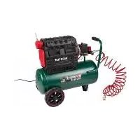
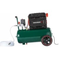
COMPRESSOR PKO 270 A5
GIE
COMPRESSOR
Operating and Safety Instructions
Translation of Original Operating Manual
FR BE
COMPRESSEUR
Before reading, unfold the page containing the illustrations and familiarise yourself with all functions of the device.
DK
GB/IE/NI Operating and Safety Instructions Page 01
Table of contents: Page:
- Introduction 3
- Device description (fig. 1-13) 3
- Scope of delivery 3
- Intended use 3
- Safety information 4
- Technical data 5
- Before starting the equipment 6
- Attachment and operation 6
- Electrical connection 6
- Cleaning, maintenance, and storage. 7
- Transport 8
- Disposal and recycling 8
- Troubleshooting 9
- Warranty certificate 10
15.Declaration of conformity 63
Explanation of the symbols

GBIE(NI)
Read and follow the operating and safety instructions before you start working with this power tool.

GBIE(NI)
Wear ear-muffs.
GBENI
Beware of hot parts! (G fig. 12)
GBJENI
Beware of electrical voltage!
GBIE(NI)
Warning! The equipment is remote-controlled and may start-up without warning.
GBJE(NI)
Caution! Before using for the first time, check the oil level and replace the oil sealing plug!

GBJE[NI]
Observe warnings and safety instructions!
1. Introduction
Manufacturer:
scheppach
we hope your new tool brings you much enjoyment and success.
Note:
According to the applicable product liability laws, the manufacturer of the device does not assume liability for damages to the product or damages caused by the product that occurs due to:
- Improper handling
Non-compliance of the operating instructions - Repairs by third parties, not by authorized service technicians
- Installation and replacement of non-original spare parts
Application other than specified - A breakdown of the electrical system that occurs due to the non-compliance of the electric regulations and VDE regulations 0100, DIN 57113 / VDE0113
We recommend:
Read through the complete text in the operating instructions before installing and commissioning the device.
The operating instructions are intended to help the user to become familiar with the machine and take advantage of its application possibilities in accordance with the recommendations.
The operating instructions contain important information on how to operate the machine safely, professionally and economically, how to avoid danger, costly repairs, reduce downtimes and how to increase reliability and service life of the machine.
In addition to the safety regulations in the operating instructions, you have to meet the applicable regulations that apply for the operation of the machine in your country.
Keep the operating instructions package with the machine at all times and store it in a plastic cover to protect it from dirt and moisture. Read the instruction manual each time before operating the machine and carefully follow its information.
The machine can only be operated by persons who were instructed concerning the operation of the machine and who are informed about the associated dangers. The minimum age requirement must be complied with.
In addition to the safety instructions contained in this operating manual and the specific regulations of your country, the technical rules generally accepted for the operation of machines of the same type must be observed.
We accept no liability for damage or accidents which arise due to non-observation of these instructions and the safety information.
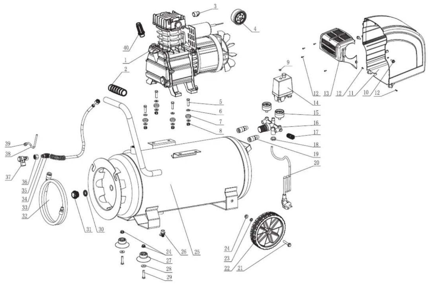
2. Device description (fig. 1-13)
- Transport handle
- Pressure switch
- Quick-lock coupling (regulated compressed air)
- Pressure gauge (for reading the preset vessel pressure)
- Pressure regulator
- Pressure gauge (for reading the vessel pressure)
- Quick-lock coupling (unregulated compressed air)
- Pressure vessel
- Supporting foot
- Drain plug for condensation water
11.Wheel - Oil drain plug
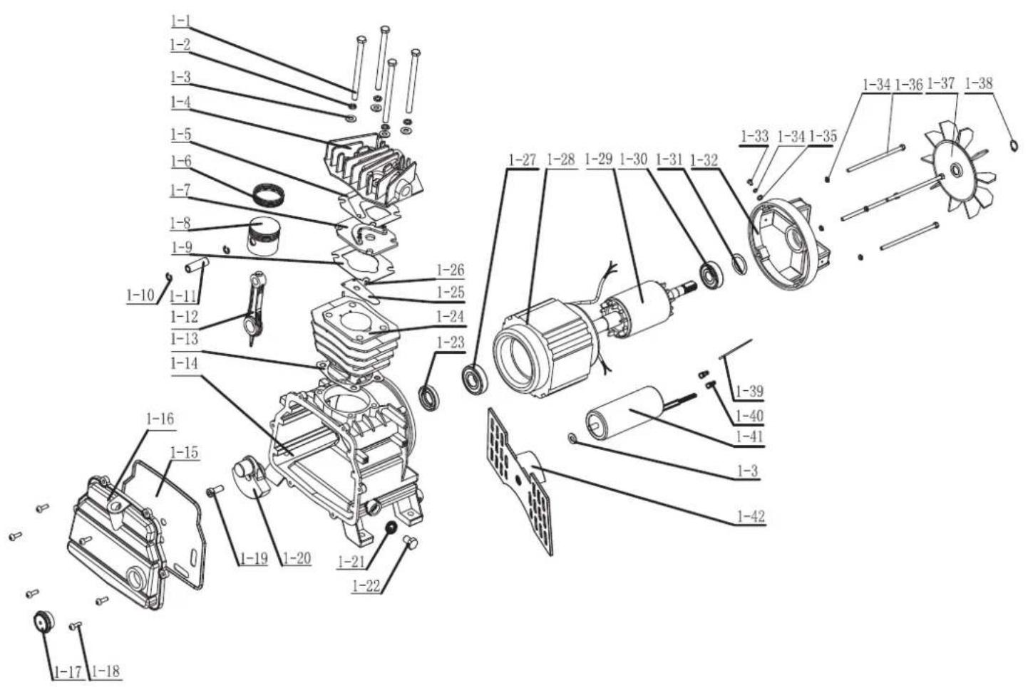
- Compressor pump
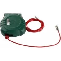
- Compressed air hose
- Air filter
- Oil sealing plug
- ON/OFF switch
- Oil level window
- Safety valve
- Oil filler opening
- Flange screw
- Washer
- Nut
- Flange nut
- Screw
3. Scope of delivery
- 1x Air filter
- 2x Supporting foot
- 2x Wheel
- 1x Mounting material
- 1x Oil sealing plug
- 1x Oil bottle
- 1x Compressed air hose
- 1x Translation of Original Operating Manual
4. Intended use
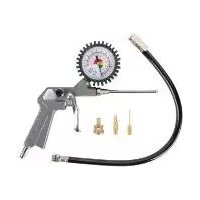
The compressor is designed to generate compressed air for compressed-air driven tools which can be driven with an air volume of up to approx. 260l / min (e.g. tire inflator, blow-out pistol and paint spray gun). Due to the limited air output it is not possible to use the compressor to drive tools with very high air consumption (for example orbital sanders, die grinders and hammer screwdrivers).
The equipment is allowed to be used only for its prescribed purpose. Any other use is deemed to be a case of misuse. The user/operator and not the manufacturer will be liable for any damage or injuries of any kind resulting from such misuse.
An element of the intended use is also the observance of the safety instructions, as well as the assembly instructions and operating information in the operating manual.
Persons who operate and maintain the machine must be familiar with the manual and must be informed about potential dangers.
In addition, the applicable accident prevention regulations must be strictly observed.
Other general occupational health and safety-related rules and regulations must be observed.
The liability of the manufacturer and resulting damages are excluded in the event of modifications of the machine.
Please note that our equipment has not been designed for use in commercial, trade or industrial applications. Our warranty will be voided if the equipment is used in commercial, trade or industrial businesses or for equivalent purposes.
5. Safety information
Attention! The following basic safety measures must be observed when using electric tools for protection against electric shock, and the risk of injury and fire. Read all these notices before using the electric tool and keep the safety instructions for later reference.
Safe work
- Keep the work area orderly
-Disorder in the work area can lead to accidents. - Take environmental influences into account
-Do not expose electric tools to rain.
-Do not use electric tools in a damp or wet environment.
There is a risk of electric shock!
-Make sure that the work area is well-illuminated.
-Do not use electric tools where there is a risk of fire or explosion. - Protect yourself from electric shock
-Avoid physical contact with earthed parts (e.g. pipes, radiators, electric ranges, cooling units). - Keep children away
-Do not allow other persons to touch the equipment or cable, keep them away from your work area. - Securely store unused electric tools
-Unused electric tools should be stored in a dry, elevated or closed location out of the reach of children. - Do not overload your electric tool
-They work better and more safely in the specified output range. - Wear suitable clothing
-Do not wear wide clothing or jewellery, which can become entangled in moving parts.
-Rubber gloves and non-slip shoes are recommended when working outdoors.
-Tie long hair back in a hair net. - Do not use the cable for purposes for which it is not intended
-Do not use the cable to pull the plug out of the outlet. Protect the cable from heat, oil and sharp edges. - Take care of your tools
-Keep your compressor clean in order to work well and safely.
-Follow the maintenance instructions.
-Check the connection cable of the electric tool regularly and have it replaced by a recognised specialist when damaged.
-Check extension cables regularly and replace them when damaged.
- Pull the plug out of the outlet
-During non-use of the electric tool or prior to maintenance and when replacing tools such as saw blades, bits, milling heads.
- Avoid inadvertent starting
-Make sure that the switch is switched off when plugging the plug into an outlet.
- Use extension cables for outdoors
-Only use approved and appropriately identified extension cables for use outdoors.
-Only use cable reels in the unrolled state.
- Remain attentive
-Pay attention to what you are doing. Remain sensible when working. Do not use the electric tool when you are distracted.
- Check the electric tool for potential damage
-Protective devices and other parts must be carefully inspected to ensure that they are fault-free and function as intended prior to continued use of the electric tool.
-Check whether the moving parts function faultlessly and do not jam or whether parts are damaged. All parts must be correctly mounted and all conditions must be fulfilled to ensure fault-free operation of the electric tool.
- Damaged protective devices and parts must be properly repaired or replaced by a recognised workshop, insofar as nothing different is specified in the operating manual.
-Damaged switches must be replaced at a customer service workshop.
-Do not use any faulty or damaged connection cables.
-Do not use any electric tool on which the switch cannot be switched on and off.
- Have your electric tool repaired by a qualified electrician
-This electric tool conforms to the applicable safety regulations. Repairs may only be performed by an electrician using original spare parts. Otherwise accidents can occur. - Important!
-For your own safety you must only use the accessories and additional units listed in the operating instructions or recommended or specified by the manufacturer. The use of mounted tools or accessories other than those recommended in the operating instructions or catalogue may place your personal safety at risk. - Noise
-Wear ear muffs when you use the compressor. - Replacing the power cable
-To prevent hazards, leave the replacement of damaged power cables strictly to the manufacturer or a qualified electrician. There is a risk of electric shock! - Inflating tires
-Directly after inflating tires, check the pressure with a suitable pressure gauge, for example at your filling station. -
Roadworthy compressors for building site operations
-Make sure that all lines and fittings are suitable for the maximum permissible operating pressure of the compressor. -
Place of installation
-Set up the compressor on an even surface. - Supply hoses at pressures above 7 bar should be equipped with a safety cable (e.g. a wire rope).
- Use flexible hoses in order to prevent transmitting unacceptable loads to the pipeline system at the connection between the compressor system and the pipeline system.
- It is essential to use separators, traps and drains which process the liquids produced by the compressor before the compressor system is put into operation.
Warning! This electric tool generates an electromagnetic field during operation. This field can impair active or passive medical implants under certain conditions. In order to prevent the risk of serious or deadly injuries, we recommend that persons with medical implants consult with their physician and the manufacturer of the medical implant prior to operating the electric tool.
Additional Safety Instructions
Safety instructions for working with compressed air and blasting guns
- The compressor pump and lines can become very hot during operation. Touching these parts will burn you.
- The air which is sucked in by the compressor must be kept free of impurities that could cause fires or explosions in the compressor pump.
- When releasing the hose coupling, hold the hose coupling piece with your hand. This way, you can protect yourself against injury from the rebounding hose.
- Wear safety goggles when working with the blow-out pistol. Foreign bodies or blown off parts can easily cause injuries.
- Do not blow at people with the blow-out pistol and do not clean clothes while being worn. Risk of injury!
Safety information for paint spraying
- Do not process any paints or solvents with a flash point below 55^ . There is a risk of explosion!
- Do not heat up paints or solvents. There is a risk of explosion!
- If hazardous liquids are processed, wear protective filter units (face guards). Also, adhere to the safety information provided by the manufacturers of such liquids.
- The details and designations of the Ordinance on Hazardous Substances, which are displayed on the outer packaging of the processed material, must be observed.
Additional protective measures are to be undertaken if necessary, particularly the wearing of suitable clothing and masks. - Do not smoke during the spraying process and/or in the work area. There is a risk of explosion! Paint vapors are easily combustible.
- Never set up or operate the equipment in the vicinity of a fire place, open lights or sparking machines.
- Do not store or eat food and drink in the work area. Paint vapors are harmful to your health.
-
The work area must exceed 30m^3 and sufficient ventilation must be ensured during spraying and drying. Do not spray against the wind. Always adhere to the regulations of the local police authority when spraying combustible or hazardous materials.
-
Do not process media such as white spirit, butyl alcohol and methylene chloride with the PVC pressure hose. These media will destroy the pressure hose.
Operating pressure vessels
- You must keep your pressure vessel in good working order, operate the vessel correctly, monitor the vessel, carry out necessary maintenance and repair work immediately and meet the relevant safety precautions.
- The supervisory authority may enforce essential control measures in individual cases.
- A pressure vessel is not allowed to be used if it has faults or deficiencies that can endanger workers or third parties.
- Check the pressure vessel for signs of rust and damage each time before using. Do not use the compressor with a damaged or rusty pressure vessel. If you discover any damage, then please contact the customer service workshop.
Do not lose these safety instructions.
Residual risk
Observe the specified maintenance and safety instructions in the instruction manual.
Always be attentive at work and keep third persons at a safe distance from your workplace.
Even with proper use of the device, a certain residual risk remains, which can not be excluded. The following potential hazards can be derived from the type and design of the device:
- Unintentional commissioning of the product
- Hearing loss if no suitable hearing protection is worn
- Wear safety glasses to prevent your eyes and face from dust and dirt particles
- Inhalation of whirled-up dust and dirt particles
6. Technical data
Mains connection 220-240 V\~ 50 Hz
Motor rating W. 1800
Operating mode .S1
Compressor speed 2850 min
Pressure vessel capacity (in liters) approx. 24
Operating pressure approx. 10 bar
Theoretical intake capacity (1/min) approx. 260
Sound power level L2A. 75.2 DB(A)
Sound power level L_WA 95.2 dB(A)
Uncertainty K. 2.11 dB
Protection type . IP20
Weight of the unit in kg approx. 27
Oil (15W 40) I............approx. 0.25
Max. altitude (above mean sea level) 1000 m
The noise emission values were measured in accordance with EN ISO 3744:2010.
Wear hearing protection.
The effects of noise can cause a loss of hearing.
7. Before starting the equipment
- Open the packaging and remove the device carefully.
- Remove the packaging material as well as the packaging and transport bracing (if available).
- Check that the delivery is complete.
- Check the device and accessory parts for transport damage.
- If possible, store the packaging until the warranty period has expired.
ATTENTION
The device and packaging materials are not toys! Children must not be allowed to play with plastic bags, film and small parts! There is a risk of swallowing and suffocation!
Before you connect the equipment to the mains supply make sure that the data on the rating plate are identical to the mains data.
- Check the equipment for damage which may have occurred in transit. Report any damage immediately to the transport company which was used to deliver the compressor.
- Install the compressor near the point of consumption.
- Avoid long air lines and supply lines (extension cables).
- Make sure that the intake air is dry and dustfree.
- Do not install the compressor in a damp or wet room.
- The compressor may only be used in suitable rooms (with good ventilation and an ambient temperature from +5^ to 40^ ). There must be no dust, acids, vapors, explosive gases or inflammable gases in the room.
- The compressor is designed to be used in dry rooms. It is prohibited to use the compressor in areas where work is conducted with sprayed water.
- The oil level in the compressor pump has to be checked before putting the equipment into operation.
8. Attachment and operation
Important!
You must fully assemble the appliance before using it for the first time!
You will require the following tools for assembly and installation:
1x Open-ended wrench size 12 mm
1x Open-ended wrench size 13 mm
1x Open-ended wrench size 14 mm (not included)
8.1 Fitting the wheels (fig. 4, 5)
- Fit the supplied wheels as shown.
8.2 Fitting the supporting feet (fig. 4, 6)
- Fit the supplied supporting foot as shown.
8.3 Fitting the air filter (fig 7, 8)
- Remove the transportation stop (B) and screw the air filter (15) to the equipment.
8.4 Changing the transportation cover (A) (fig. 9, 10)
- Remove the transport lid (A) of the oil filling opening (20).
- Fill the included compressor oil into the crank housing and insert the included oil sealing plug (16) into the oil filling opening (20).
8.5 Mains connection
- The compressor is equipped with a mains cable with shock-proof plug. This can be connected to any 220-240 V~50 Hz shock-proof socket.
- Before you use the machine, make sure that the mains voltage is the same as the operating voltage (see the rating plate).
- Long supply cables, extensions, cable reels etc. cause a drop in voltage and can impede motor start-up.
- At low temperatures below +5^ , sluggishness may make starting difficult or impossible.
8.6 ON/OFF switch (fig. 2)
- Pull the ON/OFF switch (17) upwards to switch on the compressor. To switch off the compressor, press the ON/OFF switch down.
8.7 Setting the pressure (fig. 1, 3)
- Use the pressure regulator (5) to set the pressure on the pressure gauge (4).
- The set pressure can be drawn from the quick lock coupling (3).
- The vessel pressure can be read off the pressure gauge (6).
- The vessel pressure is drawn from the quick lock coupling (7).
8.8 Setting the pressure switch (fig. 1)
The pressure switch (2) is set at the factory.
- Cut-in pressure approx. 8 bar
- Cut-out pressure approx. 10 bar.
8.9 Fitting the compressed air hose (fig. 1, 3)
- Use the compressed air hose (14) if you intend to carry out work at a greater distance from the compressor. To do so, connect the nipple (H) on the compressed air hose to one of the quick release couplings (3, 7). Then attach the compressed air tool to the quick-release coupling (I) on the compressed air hose.
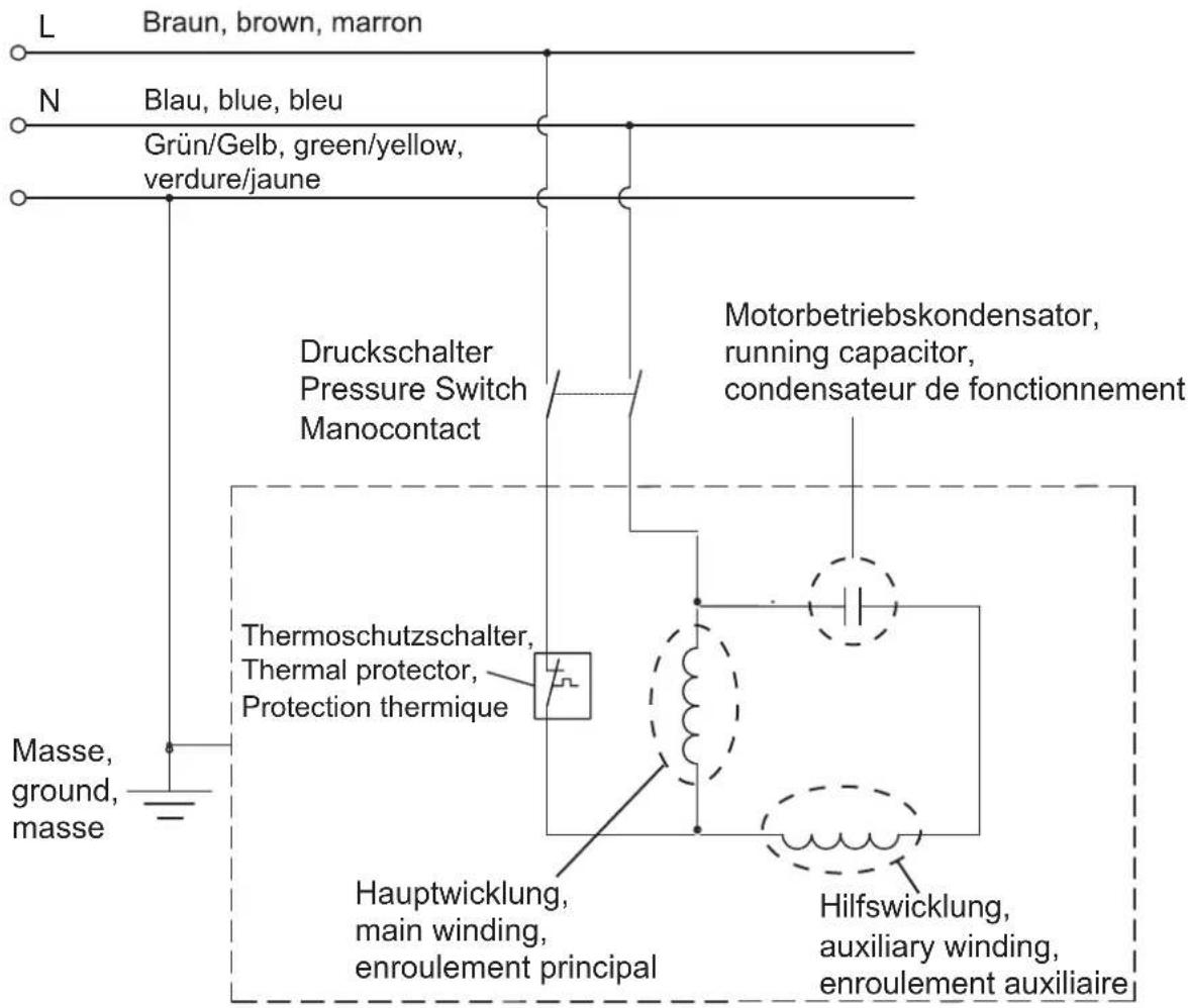
9. Electrical connection
The electrical motor installed is connected and ready for operation. The connection complies with the applicable VDE and DIN provisions. The customer's mains connection as well as the extension cable used must also comply with these regulations.
Important information
In the event of an overloading the motor will switch itself off. After a cool-down period (time varies) the motor can be switched back on again.
Damaged electrical connection cable
The insulation on electrical connection cables is often damaged.
This may have the following causes:
Passage points, where connection cables are passed through windows or doors
- Kinks where the connection cable has been improperly fastened or routed
- Places where the connection cables have been cut due to being driven over
Insulation damage due to being ripped out of the wall outlet
- Cracks due to the insulation ageing
Such damaged electrical connection cables must not be used and are life-threatening due to the insulation damage.
Check the electrical connection cables for damage regularly.
Make sure that the connection cable does not hang on the power network during the inspection.
Electrical connection cables must comply with the applicable VDE and DIN provisions. Only use connection cables with the marking "HOSVV-F".
The printing of the type designation on the connection cable is mandatory.
AC motor
The mains voltage must be 220 - 240V
- Extension cables up to 25m long must have a cross-section of 1.5mm^2
Connections and repairs of electrical equipment may only be carried out by an electrician.
Please provide the following information in the event of any enquiries:
Type of current for the motor
- Machine data - type plate
Machine data - type plate
10. Cleaning, maintenance, and storage
Important!
Pull out the power plug before doing any cleaning and maintenance work on the equipment. Risk of injury from electric shock!
Important!
Wait until the equipment has cooled down completely! Risk of burns!
Important!
Always depressurize the equipment before carrying out any cleaning and maintenance work! Risk of injury!
10.1 Cleaning
- Keep the equipment free of dirt and dust as far as possible. Wipe the equipment with a clean cloth or blow it down with compressed air at low pressure.
We recommend that you clean the equipment immediately after you use it. -
Clean the equipment regularly with a damp cloth and some soft soap. Do not use cleaning agents or solvents; these may be aggressive to the plastic parts in the equipment. Ensure that no water can get into the interior of the equipment.
-
You must disconnect the hose and any spraying tools from the compressor before cleaning. Do not clean the compressor with water, solvents or the like.
10.2 Maintenance work on the pressure vessel (fig. 1)
Important! To ensure a long service life of the pressure vessel (8), drain off the condensed water by opening the drain valve (10) each time after using. Release the vessel pressure first (see 10.7.1). Open the drain screw by turning counterclockwise (looking at the screw from the bottom of the compressor) so that all the condensed water can run out of the pressure vessel. Then close the drain screw again (turn it clockwise). Check the pressure vessel for signs of rust and damage each time before using.
Do not use the compressor with a damaged or rusty pressure vessel. If you discover any damage, then please contact the customer service workshop.
Important!
The condensed water from the pressure vessel will contain residual oil. Dispose of the condensed water in an environmentally compatible manner at a suitable collection point.
10.3 Safety valve (fig. 3)
The safety valve (19) has been set for the highest permitted pressure of the pressure vessel. It is prohibited to adjust the safety valve or remove its seal. Actuate the safety valve from time to time to ensure that it works when required. Pull the ring with sufficient force until you can hear the compressed air being released. Then release the ring again.
10.4 Checking the oil level at regular intervals (fig. 11)
Place the compressor on a level and straight surface.
The oil level must be between the MAX and MIN marks on the oil level window (18).
Oil change: we recommend SAE 15W 40 or equivalent. The original oil filling must be changed after 100 hours in operation; thereafter the oil must be drained and replaced with new oil after every 500 hours in operation.
10.5 Changing the oil (fig. 1, 10, 11)
Switch off the engine and pull the mains plug out of the socket. Remove the oil sealing plug (16). After releasing any air pressure you can unscrew the oil drain plug (12) from the compressor pump (13).
To prevent the oil from running out in an uncontrolled manner, hold a small metal chute under the opening and collect the oil in a vessel. If the oil does not drain out completely, we recommend tilting the compressor slightly. When the oil has drained out, re-fit the oil drain plug (12).
Dispose of the old oil at a drop-off point for old oil.
To fill in the correct quantity of oil, make sure that the compressor stands on an even surface. Fill new oil through the oil filler opening (20) until it comes up to the maximum level. This is marked with a red dot on the oil level window (18) (fig. 11). Do not exceed the maximum filling quantity. Overfilling the equipment may result in damage. Reinsert the oil sealing plug (16) into the oil filler opening (20).
10.6 Cleaning the intake filter (fig. 3, 12, 13)
The intake filter prevents dust and dirt being drawn in. It is essential to clean this filter after at least every 300 hours in service. A clogged intake filter will decrease the compressor's performance dramatically.
Open the thumb screw (E) to the remove the intake filter.
Then pull off the filter cover (C). Now you can remove the air filter (F) and the filter housing (D). Carefully tap out the air filter, filter cover and filter housing. Then blow out these parts with compressed air (approx. 3 bar) and reinstall in reverse order.
10.7 Storage
Important!
Pull out the mains plug and ventilate the equipment and all connected pneumatic tools. Switch off the compressor and make sure that it is secured in such a way that it cannot be started up again by any unauthorized person.
Important!
Store the compressor only in a dry location which is not accessible to unauthorized persons. Always store upright, never tilted! Oil may leak out!
10.7.1 Releasing excess pressure
Release the excess pressure by switching off the compressor and using the compressed air which is still left in the pressure vessel, e.g. with a compressed air tool running in idle mode or with a blow-out pistol.
11. Transport
For transport, use the transport handle (1) and drive the compressor with it.
Observe the weight when lifting the compressor (see Technical Data).
When transporting the compressor in a motor vehicle, ensure good load securing.
12. Disposal and recycling
The equipment is supplied in packaging to prevent it from being damaged in transit. The raw materials in this packaging can be reused or recycled.
The equipment and its accessories are made of various types of material, such as metal and plastic. Defective components must be disposed of as special waste. Ask your dealer or your local council.

The packaging is wholly composed of environmentally-friendly materials that can be disposed of at a local recycling centre.
Contact your local refuse disposal authority for more details of how to dispose of your worn out electrical devices.
Old devices must not be disposed of with household waste!
This symbol indicates that this product must not be disposed of together with domestic waste in compliance with the Directive (2012/19/EU) pertaining to waste electrical and electronic equipment (WEEE). This prod
uct must be disposed of at a designated collection point. This can occur, for example, by handing it in at an authorised collecting point for the recycling of waste electrical and electronic equipment. Improper handling of waste equipment may have negative consequences for the environment and human health due to potentially hazardous substances that are often contained in electrical and electronic equipment. By properly disposing of this product, you are also contributing to the effective use of natural resources. You can obtain information on collection points for waste equipment from your municipal administration, public waste disposal authority, an authorised body for the disposal of waste electrical and electronic equipment or your waste disposal company.
13.Troubleshooting
| Fault Possible cause | Remedy | |
| The compressor does not start. | ·No supply voltage. ·Insufficient supply voltage. ·Outside temperature is too low. ·Motor is overheated. | ·Check the supply voltage, the power plug and the socket-outlet. ·Make sure that the extension cable is not too long. Use an extension cable with large enough wires. ·Never operate with an outside temperature of below +5 °C. ·Allow the motor to cool down. If necessary, remedy the cause of the overheating. |
| The compressor starts but there is no pressure. | ·The non-return valve (19) leaks. ·The seals are damaged. ·The drain plug for condensation water (10) leaks. | ·Contact your local service centre. Every attempt to carry out a repair, can be dangerous if it is not done by skilled personnel. ·Check the seals and have any damaged seals replaced by a service center. ·Tighten the screw by hand.. Check the seal on the screw and replace if necessary. |
| The compressor starts, pressure is shown on the pressure gauge, but the tools do not start. | ·The hose connections have a leak. ·A quick-lock coupling has a leak. ·Insufficient pressure set on the pressure regulator (5). | ·Check the compressed air hose and tools and replace if necessary. ·Contact your local service centre. Every attempt to carry out a repair, can be dangerous if it is not done by skilled personnel. ·Increase the set pressure with the pressure regulator. |
Service information
Please note that the following parts of this product are subject to normal or natural wear and that the following parts are therefore also required for use as consumables.
Wear parts*: intake filter
- Not necessarily included in the scope of delivery!
14.Warranty certificate
Dear Customer,
All of our products undergo strict quality checks to ensure that they reach you in perfect condition. In the unlikely event that your device develops a fault, please contact our service department at the address shown on this guarantee card. Of course, if you would prefer to call us then we are also happy to offer our assistance under the service number printed below. Please note the following terms under which guarantee claims can be made:
These guarantee terms cover additional guarantee rights and do not affect your statutory warranty rights. We do not charge you for this guarantee.
- Our guarantee only covers problems caused by material or manufacturing defects, and it is restricted to the rectification of these defects or replacement of the device. Please note that our devices have not been designed for use in commercial, trade or industrial applications. Consequently, the guarantee is invalidated if the equipment is used in commercial, trade or industrial applications or for other equivalent activities. The following are also excluded from our guarantee: compensation for transport damage, damage caused by failure to comply with the installation/assembly instructions or damage caused by unprofessional installation, failure to comply with the operating instructions (e.g. connection to the wrong mains voltage or current type), misuse or inappropriate use (such as overloading of the device or use of non-approved tools or accessories), failure to comply with the maintenance and safety regulations, ingress of foreign bodies into the device (e.g. sand, stones or dust), effects of force or external influences (e.g. damage caused by the device being dropped) and normal wear resulting from proper operation of the device.
The guarantee is rendered null and void if any attempt is made to tamper with the device.
- The guarantee is valid for a period of 3 years starting from the purchase date of the device. Guarantee claims should be submitted before the end of the guarantee period within two weeks of the defect being noticed. No guarantee claims will be accepted after the end of the guarantee period. The original guarantee period remains applicable to the device even if repairs are carried out or parts are replaced. In such cases, the work performed or parts fitted will not result in an extension of the guarantee period, and no new guarantee will become active for the work performed or parts fitted. This also applies when an on-site service is used.
In order to assert your guarantee claim, please send your defective device postage-free to the address shown below. Please enclose either the original or a copy of your sales receipt or another dated proof of purchase. Please keep your sales receipt in a safe place, as it is your proof of purchase. It would help us if you could describe the nature of the problem in as much detail as possible. If the defect is covered by our guarantee then your device will either be repaired immediately and returned to you, or we will send you a new device.
Of course, we are also happy offer a chargeable repair service for any defects which are not covered by the scope of this guarantee or for units which are no longer covered. To take advantage of this service, please send the device to our service address.
Service-Hotline (GB/IE/NI):
+80040034003
(0,00 EUR/Min.)
Service-Email (GB):
service.GB@scheppach.com
Service-Email (IE/NI):
service.IE@scheppach.com
Service Address (GB/IE/NI):
Doyles Wholesale
Dublind Road
Castlecomer, Co. Kilkenny R95AP6F

At www.lidl-service.com you can download this and many more manuals, product videos plus installation software.
The QR code takes you directly to the Lidl service page (www.lidl-service.com) and you can open your operating manual by entering the article number (IAN) 315462.
Nosyou'recommendands:
Chere Cients, Cher Client
Service-hotline (BE):
+80040034003
0,00 /Min.
Service-Email (FR):
service.FR@scheppach.com
E-mailadres (BE):
service.BE@scheppach.com
service.NL@scheppach.com
E-mailadres / Service-Email (BE):
service.BE@scheppach.com
Serviceadres/Adresse du service (NL/BE):
Aeroupyia doxiwv nieons
Otoioic leitoupei doxelo nleonte va povntei va to diatnpie o ayoyn kataotaan kai owot,va to napakoou-0ei kai va laubavei aedeo ta avaykaia etpa emokuenckai ouvtponc kai ta atapaitnaetpaaosfaeias.
- 2e opioevc nepimwoeic npopei n enontouoaa Apx va diatae ie peta ennttuocn.
- Ev πππρεπται ηλειρουγλ δόχειου πεος, εὰν ελον έλατιμακό ἡν αποτελεί κύδυνο για τοῦ χερισές, ἡλλα τρλί τροσωπα.
Na eEyxete to doxieo nieoc npiv ano kaeioupyia yia oKoupia kai bace. O ouitieotnc dev etipetetai va leioupyei e atuataiko n okoupiaoevo doxieio nieoc. Eav diantiotwete bace, etikoivwnote e to ouvepyeio eguntn-petnons nelaatwv.
Na e kaia autic tic Obnyic xphonc.
Ynoaimóevou kivduvou
Tnpelte nK aOopioeveo oynieoc ouvnipnnc kai aodaeiaoc otic oyniec xphons.
Nvta va eioe npoektikoi kata tyn epyaia kai va kpatnoepi ta npoana o aofa anoataon to xwpo epyaolac aoc.
Akoun kai me tn oawton xpon tnc ouakeun, evac opiaevoc unoaleioevoc kivduoc napapevei, to otio 1ev 1npel va atokkeiotei. Ta akoloutheta i thavoiv kivduov mtopov va npolehouv an tov toto kai to oxediaaog ncs ouakeun:
akouia 0eon o einoupyia tou npoiovtroc.
H anwaiia nca akonc evxie oapei dev katalnn npo-otaia nca kono.
- Dopate yuaia aoaiaic ia va anotpeyia taia oac kai va aviuetwiia ano tn okovn kai n bpwia oomegaia.
H 10Voh oToPoBilizovTahup kOcvn kai BpWua OuaTiaia.
6. Texvika xapaktnpiotiká
Piieon Aetoupyiae .1ep. 10 bar
p 10xucavappofoans (I/min) ca.260
Emiteo nxtikicpiocnLFA. 75.2dB(A)
Ei0s npoostaia .IP20
Bapoc ouokeunc oE kg. 27
AδI (15W 40) I . . . . . . . . . . . . . . . . . . . . . . . . . . . . . . . . . . . . . . . . . . . . . . . . . . . . . . . . . . .
Meyioto uoepetpo
Avoiktn ypaumn oipic (GR/CY):
+80040034003
{0,00 €/Min.)
e mail (GR):
service.GR@scheppach.com
Aieuovon e-mail (CY):
service.CY@scheppach.com
AieuOuvon oepic GR/CY):
GEORGE C SOLOMONIDES & SON LTD
PO.BOX56236/169,LEONTIOSA
GR-3305 LIMASSOL/CYPRUS

AnTn tieuovon www.lidl-service.com nopelte va kateBaoet e auto kai nlaa aa ayyeipia, bivteo npoiovv kai loyioik oekataotaonc.
MeTovKwDikaQRetaBaiveTe aentueoieac otn eiaidaeEunptnpntnoCtouLidl (www.lidl-service.com) kai mtopeite va avolxiTe Tc ondyic xphonoc ac Eioayovracc ToV KwDko poiovtoc (IAN) 315462.
Inhalt:Seite:
service.AT@scheppach.com
service.CH@scheppach.com
Service Adresse (DE): Service Adresse (AT): Service Adresse (CH):
Standard references:
EN 1012-1:2010; EN 60204-1:2006/A1:2009; EN 61000-6-1:2007; EN 61000-6-3:2007/A1:2011; EN 50581:2012; EN 286-1:1998/A1:2002
This declaration of conformity is issued under the sole responsibility of the manufacturer.
The object of the declaration described above fulfils the regulations of the directive 2011/65/EU of the European Parliament and Council from 8th June 2011, on the restriction of the use of certain hazardous substances in electrical and electronic equipment.
Subject to change without notice
Documents registrar: Andreas Pecher
Günzburgr. 69, D-89335 Ichenhausen