CT 8SW - Subwoofer BOWERS & WILKINS - Free user manual and instructions
Find the device manual for free CT 8SW BOWERS & WILKINS in PDF.
| Product type | Subwoofer |
| Brand | Bowers & Wilkins |
| Model | CT 8SW |
| Category | Custom Theatre |
| Application | Wall mounting or integration into a Home Cinema cabinet |
| Amplification type | Passive (requires external amplifier) |
| Pairing | Can be paired with each main speaker to extend bass response |
| Frequency response | Below 20 Hz (extreme bass) |
| Recommended amplifier power | Varies by installation; refer to specifications |
| Maintenance | Dusting with a soft, dry cloth |
| Cleaning | Do not use liquid products; avoid touching the speaker cones |
| Safety | Do not expose to moisture; follow electrical safety guidelines |
| Ecology | Compliant with RoHS and WEEE directives; recyclable at end of life |
| Warranty | 5 years for the passive speaker, 2 years for associated electronic components |
| Break-in period | Approximately 15 hours of normal use to stabilize the suspensions |
| Installation precautions | Do not place near heat sources, moisture, or strong magnetic fields |
| Decoupling | Use the provided spikes to prevent vibrations and protect the floor |
| Cabling | Use a connecting cable with impedance less than 0.1 Ω |
| Included accessories | Decoupling spikes, installation and user manual |
| Storage | In a temperate environment; avoid freezing |
Frequently Asked Questions - CT 8SW BOWERS & WILKINS
User questions about CT 8SW BOWERS & WILKINS
0 question about this device. Answer the ones you know or ask your own.
Ask a new question about this device
Download the instructions for your Subwoofer in PDF format for free! Find your manual CT 8SW - BOWERS & WILKINS and take your electronic device back in hand. On this page are published all the documents necessary for the use of your device. CT 8SW by BOWERS & WILKINS.
USER MANUAL CT 8SW BOWERS & WILKINS
natural_image
Interior of a movie theater with red seats and a large screen displaying a gorilla (no visible text or symbols)Contents
English
Installation and
Setup Manual ......2
Limited Warranty......4
Français
Conformity .....50–51
Technical
Specifications .....52–56
English Installation and Setup Manual
Important Safety Instructions
- Read these instructions.
- Keep these instructions.
- Heed all warnings.
- Follow all instructions.
- Do not use this apparatus near water.
-
Clean only with dry cloth.
-
Do not block any ventilation openings. Install in accordance with the manufacturer's instructions.
-
Do not install near any heat sources such as radiators, heat registers, stoves, or other apparatus (including amplifiers) that produce heat.
-
Do not defeat the safety purpose of the polarized or grounding-type plug. A polarized plug has two blades with one wider than the other. A grounding type plug has two blades and a third grounding prong. The wide blade or the third prong are provided for your safety. If the provided plug does not fit into your outlet, consult an electrician for replacement of the obsolete outlet.
-
Protect the power cord from being walked on or pinched particularly at plugs, convenience receptacles, and the point where they exit from the apparatus.
-
Only use attachments/accessories specified by the manufacturer.
-
Use only with the cart, stand, tripod, bracket, or table specified by the manufacturer, or sold with the apparatus. When a cart is used, use caution when moving the cart/apparatus combination to avoid injury from tip-over.
-
Unplug this apparatus during lightning storms or when unused for long periods of time.
-
Refer all servicing to qualified service personnel. Servicing is required when the apparatus has been damaged in any way, such as power-supply cord or plug is damaged, liquid has been spilled or objects have fallen into the apparatus, the apparatus has been exposed to rain or moisture, does not operate normally, or has been dropped.
-
Do not expose this apparatus to dripping or splashing and ensure that no objects filled with liquids, such as vases, are placed on the apparatus.
-
To completely disconnect this apparatus from the AC Mains, disconnect the power supply cord plug from the AC receptacle.
-
The mains plug of the power supply cord shall remain readily operable.
- Do not expose batteries to excessive heat such as sunshine, fire or the like.
The lightning flash with arrowhead symbol within an equilateral triangle, is intended to alert the user to the presence of uninsulated “dangerous voltage” within the product’s enclosure that may be of sufficient magnitude to constitute a risk of electric shock to persons.

The exclamation point within an equilateral triangle is intended to alert the user to the presence of important operating and maintenance (servicing) instructions in the literature accompanying the product.
WARNING: To reduce the risk of fire or electric shock, do not expose this apparatus to rain or moisture.
- When replacement parts are required, be sure the service technician has used replacement parts specified by the manufacturer or have the same characteristics as the original part. Unauthorised substitutions may result in fire, electric shock or other hazards.
- Check that there are no cables under the carpet that may be damaged by the spike feet. Do not walk the product on the spike feet as this may cause them to become detached from the cabinet and cause damage. Take care not to impale yourself with the spike feet.
- For continued protection against fire hazard, use fuses only of the correct type and rating. Mains fuses are located inside the appliance as well as on its back panel. Replacement of the internal fuse should be entrusted to an authorised operative. User-replaceable fuse types are shown in the specification.
- Isolation of the appliance from the power supply is by means of removal of the power cord from the rear of the appliance or removal of the power cord from the wall power outlet. Either the wall outlet or the rear of the appliance must remain freely accessible at all times while the apparatus is in use.
- This product should be operated only from the type of power source indicated by the marking adjacent to the power cord entry. If you are not sure of the type of power supply to your home, consult your product dealer or local power company.
- Do not overload wall outlets, extension cords or integral convenience receptacles, as this can result in a risk of fire or electric shock.
- Magnetic fields - The product creates a stray static magnetic field. Do not place any object that may be damaged by this magnetic field (eg
cathode ray tube televisions or computer monitors, audio and video tapes and swipe cards) within 0.5m (2 feet) of the appliance. The appliance may cause distortion of cathode ray tube images beyond this distance. LCD and Plasma screens are not affected.
- Mounting – Do not place this product on an unstable stand, tripod, bracket or table. The product may fall causing serious injury and serious damage. Any mounting of the product should follow the manufacturer's instructions.
Do not expose the device to rain, use it near water or in damp or wet conditions, or place containers on it containing liquids which might spill into any openings.
When setting up the device, make sure that the AC outlet you are using is easily accessible. If some trouble or malfunction occurs, immediately turn off the power switch and disconnect the plug from the outlet. Even when the power switch is turned off, electricity is still flowing to the product at the minimum level. When you are not using the device for a long time, make sure to unplug the power cord from the wall AC outlet.
Environmental Information
All B&W products are designed to comply with international directives on the Restriction of Hazardous Substances
(RoHS) in electrical and electronic equipment and the disposal of Waste Electrical and Electronic Equipment (WEEE). These symbols indicate compliance and that the products must be appropriately recycled or processed in accordance with these directives. Consult your local waste disposal authority for guidance.
This manual covers the CT SW10 and CT SW12 subwoofers and their matching SA1000 remote control rack mount power amplifier.
Introduction
Dear customer,
Thank you for purchasing a Bowers and Wilkins Custom Theatre system.
Since its foundation in 1966, the continuing philosophy of B&W has been the quest for perfect sound reproduction. Inspired by the company's founder, the late John Bowers, this quest has entailed not only high investment in audio technology and innovation but also an abiding appreciation of music and movies to ensure that the technology is put to maximum effect.
Custom Theatre speakers are specifically designed to be built into the fabric of the listening room or into custom furniture as part of a fully designed theatre concept. To that end, they incorporate several features that enable them to be adapted to a wide range of installation conditions and deliver superb sound quality. However, they specifically do not incorporate features found on some other B&W products that are not appropriate to this type of installation. An example of such a feature would be tweeter on top, which only operates well with a free-standing speaker. Furthermore, because of the normal custom install practice of hiding built-in speakers with acoustically transparent cloth that matches the décor, all the models except one are supplied without grilles. The exception is the CT8 DS surround speaker, which needs to protrude into the room in order for the side-firing drivers to operate properly.
No matter how good the speakers themselves may be, they will not deliver their full potential unless properly installed. Please read through this manual fully. It will help you optimise the performance of the system.
B&W distributes to over 60 countries worldwide and maintains a network of dedicated distributors who will be able to help should you have any problems your dealer cannot resolve.
Although the speakers are semi-active and require an active crossover, all power amplification must be separately sourced. Each CT8 LR, CT8 CC and CT8 DS requires two channels of power amplification, or three if used with a CT8 SW subwoofer. This allows the user maximum flexibility in choosing these components.
The CT8 SW subwoofer, unlike the majority of subwoofers currently available, does not contain its own power amplifier and is used in a different manner than is usual. The original concept of home theatre based on various Dolby Digital and DTS systems advocates five or more main channels plus a single Low Frequency Effects (LFE) channel. The main channels contain full range signals and the LFE channel contains special effects up to approximately 140Hz. Recognising that many people do not want five or more full-range speakers in one room, Dolby Digital and DTS systems allow for the main channels to operate with small speakers having a restricted bass extension. The lowest frequencies from these channels are filtered off and added to the LFE channel to be reproduced by a subwoofer. The filter cut-off frequency is normally set at around 80Hz, the rationale being that sound gets progressively less directional the lower the frequency and localisation becomes less important. This is true to some extent, but the ears can process directional information at very low frequencies and the more the bass of the main channels is extended, the more realistic the sound stage becomes. Many high-end processors offer lower filter cut-off frequencies for this very reason.
To preserve this directional information, a CT8 SW may be added to each of the main channels as desired, extending the frequency response well below 20Hz. The minimum recommended configuration is to assign one subwoofer to each of the front left and right channels, restoring some directional information to the action directly on the screen and full directional information to 2-channel audio programme. The sense of spatial acoustic improves as more subwoofers are added to the remaining channels. If higher sound levels are required for larger listening environments and greater realism, up to two subwoofers may be added to each main channel. (It should be noted here that the addition of more subwoofers to any single channel requires an adjustment of the subwoofer
output level of that channel's CT8 XO in order to restore the correct tonal balance.) The LFE channel is then distributed to all the main channels that have a subwoofer assigned by the simple action of configuring the surround processor as if there were no subwoofer present and specifying where the LFE signal should be routed. Strictly speaking, the phrase "no subwoofer" here means "no subwoofer dedicated to the LFE channel".
Safety Warning!

A CT800 system is capable of producing very high sound pressure levels. Prolonged exposure to high sound levels can lead first to temporary and later
permanent hearing damage. Do not exceed recommended Leq (equivalent sound level) exposure levels, for example, those specified in ISO 1999:1990.
Running In and Ancillary Equipment Ancillary Equipment
Speakers of this ability deserve signals of the highest quality. Choose your electronic equipment and interconnecting cables with care. We can give guidance on what to look for when choosing ancillary equipment, but cannot recommend specific items. The standards of such products are improving all the time and your dealer will be able to demonstrate a variety of suitable up-to-date products.
In the specification we recommend a range of amplifier powers. The higher figure is defined by the power handling capability of the speaker. When calculating the power handling, it is assumed that the amplifier is not run into clipping, which distorts the frequency power spectrum of the signal, and that the signal is normal programme material. Test tones from oscillators and the like are not applicable. The lower figure is the minimum we consider necessary to achieve reasonable listening levels without audible distortion in the smaller room (less than 60 m ^3 or 2000 cu ft). The higher the power you use, the less likely you are to experience amplifier clipping.
You can often tell how good an amplifier is at driving complex speaker loads by looking at its power rating into both 4Ω and 8Ω loads. The nearer the ratio is to 2:1 the better, as it indicates a good current capability.
In order to reduce the effect the cable has on the frequency response of the speaker to inaudible levels, the impedance of the cable at all frequencies (measuring both positive and negative conductors in series) should be kept as low as possible and certainly below 0.1Ω. At low frequencies, the DC resistance of the cable is the dominant factor and you should choose a gauge of wire sufficient to achieve the impedance requirements over the length of cable you need to use. At mid and high frequencies the inductive component of the impedance can dominate the DC resistance. This and other properties influenced by the detailed construction of the cable become important.
Running In
The performance of the speakers will change subtly during the initial listening period. If they have been stored in a cold environment, the damping compounds and suspension materials will take some time to recover their correct mechanical properties. The drive unit suspensions will also loosen up during the first hours of use. The time taken for the speakers to achieve their intended performance will vary depending on previous storage conditions and how they are used. As a guide, allow up to a week for the temperature effects to stabilise and 15 hours of average use for the mechanical parts to attain their intended design characteristics.
However, longer run-in periods (as long as a month) have been reported and there is evidence to suggest that this has little to do with the speaker changing and more to do with the listener getting used to a new sound. It is especially so with highly revealing speakers such as these, where there may be a significant increase in the amount of detail portrayed compared to what the listener has previously been used to; the sound may at first appear too "up front" and perhaps a little hard. After an extended period of time, the sound will seem to mellow, but without losing clarity and detail.
Aftercare
The speaker cabinet surfaces and the casing of the CT8 XO usually only require dusting. If you wish to use an aerosol cleaner, remove any speaker grilles first by gripping round the edges and gently pulling them away from the cabinet. Spray onto the cleaning cloth, not directly onto the cabinet. The grille fabric may be cleaned with a normal clothes brush whilst the grille is detached from the cabinet.
When replacing grilles, ensure that the pegs are correctly aligned with the receptacles in the cabinet before pushing into place.
Avoid touching the drive unit diaphragms, especially the tweeter, as damage may result.
Limited Warranty
This product has been designed and manufactured to the highest quality standards. However, if something does go wrong with this product, B&W Group Ltd. and its national distributors warrant free of charge labour (exclusion may apply) and replacement parts in any country served by an official B&W distributor.
This limited warranty is valid for a period of five years from the date of purchase or two years for electronics including amplified loudspeakers.
Terms and Conditions
1 The warranty is limited to the repair of the equipment. Neither transportation, nor any other costs, nor any risk for removal, transportation and installation of products is covered by this warranty.
2 This warranty is only valid for the original owner. It is not transferable.
3 This warranty will not be applicable in cases other than defects in materials and/or workmanship at the time of purchase and will not be applicable:
a. for damages caused by incorrect installation, connection or packing,
b. for damages caused by any use other than correct use described in the user manual, negligence, modifications, or use of parts that are not made or authorised by B&W,
c. for damages caused by faulty or unsuitable ancillary equipment,
d. for damages caused by accidents, lightning, water, fire heat, war, public disturbances or any other cause beyond the reasonable control of B&W and its appointed distributors,
e. for products whose serial number has been altered, deleted, removed or made illegible,
f. if repairs or modifications have been executed by an unauthorised person.
4 This guarantee complements any national/regional law obligations of dealers or national distributors and does not affect your statutory rights as a customer.
How to claim repairs under warranty
Should service be required, please follow the following procedure:
1 If the equipment is being used in the country of purchase, you should contact the B&W authorised dealer from whom the equipment was purchased.
2 If the equipment is being used outside the country of purchase, you should contact the B&W national distributor in the country of residence, who will advise where the equipment can be serviced. You can call B&W in the UK or visit our web site to get the contact details of your local distributor.
To validate your warranty, you will need to produce the warranty booklet completed and stamped by your dealer on the date of purchase. Alternatively, you will need the original sales invoice or other proof of ownership and date of purchase.
Français
STANDARDS CONFORMITY
NORTH AMERICA

Conforms to ANSI/UL Standard 60065 7th Edition
ertified to CAN/CSA Standard C22.2 No. 60065

Complies with Part 15 of the FCC Rules
Operation is subject to the following conditions:
- This device does not cause harmful interference and
- This device must accept any interference received, including interference that may cause undesired operation.
EU DECLARATION OF CONFORMITY
We,
B&W Group Ltd.
whose registered office is situated at
Dale Road, Worthing, West Sussex, BN11 2BH, United Kingdom
declare under our sole responsibility that the products:
CT8 XO
comply with the EU Electro-Magnetic Compatibility (EMC) Directive 89/336/EEC, in pursuance of which the following standards have been applied:
EN 55020 : 2002
Sound and television broadcast receivers and associated equipment - Immunity characteristics
EN 55013:2001
Sound and television broadcast receivers and associated equipment - Radio disturbance characteristics
EN 61000-3-2 : 2000
Electro-magnetic compatibility (EMC) — Part 3-2: Limits - Limits for harmonic current emissions (equipment input current up to and including 16A per phase)
EN 61000-3-3 : 1995
Electro-magnetic compatibility (EMC) — Part 3-3: Limits - Limitation of voltage changes, voltage fluctuations and flicker in public low-voltage supply systems, for equipment with rated current ≤ 16A per phase and not subject to conditional connection
and comply with the EU Low Voltage Directive 73/23/EEC and amendment 93/68/EEC, in pursuance of which the following standard has been applied:
EN 60065 : 2002
Audio, video and similar electronic apparatus - Safety requirements
This declaration attests that the manufacturing process quality control and product documentation accord with the need to assure continued compliance.
The attention of the user is drawn to any special measures regarding the use of this equipment that may be detailed in the owner's manual.
Signed:

G Edwards
Executive Vice President, Operations
B&W Group Ltd.
EU DECLARATION OF CONFORMITY
We,
B&W Group Ltd.
whose registered office is situated at
Dale Road, Worthing, West Sussex, BN11 2BH, United Kingdom
declare under our sole responsibility that the products:
CT8 LR, CT8 DS, CT8 CC, CT8 SW
comply with the EU Electro-Magnetic Compatibility (EMC) Directive 89/336/EEC, in pursuance of which the following standards have been applied:
EN 61000-6-1 : 2001
EN 61000-6-3 : 2001
EN 55020 : 2002
EN 55013 : 2001
and comply with the EU General Product Safety 2001/95/EC, in pursuance of which the following standard has been applied:
EN 60065 : 2002
This declaration attests that the manufacturing process quality control and product documentation accord with the need to assure continued compliance.
The attention of the user is drawn to any special measures regarding the use of this equipment that may be detailed in the owner's manual.
Signed:

G Edwards
Executive Vice President, Operations
B&W Group Ltd.
natural_image
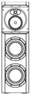
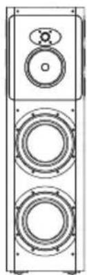
Technical line drawing of a multi-tiered speaker tower with two circular speakers (no text or symbols)CT8 LR
Description 3-way closed-box system
Drive Units 1x ∅32mm (1 14 in) metal dome high-frequency 1x ∅150mm (6 in) woven Kevlar® cone FST™ midrange 2x ∅250mm (10 in) Rohacell® cone bass
Frequency Range -6dB at 23Hz and 40kHz
Frequency Response 29Hz - 24kHz ±3dB on reference axis
Dispersion Within 2dB of reference response Horizontal: over 60° arc Vertical: over 10° arc
Sensitivity 93dB spl (2.83V, 1m) (mf/hf)
Harmonic Distortion 2nd and 3rd harmonics (90dB, 1m) <1% 45Hz – 20kHz <0.5% 55Hz – 20kHz
Nominal Impedance 8Ω (minimum 4Ω)
Crossover Frequency 300Hz, 4kHz
Recommended Amplifier Power 500W - 1000W into 8Ωon unclipped programme
Max Recommended 0.1Ω Cable Impedance
Dimensions Height: 1100mm (43.3 in) (without spike feet) Width: 325mm (12.8 in) Depth: 550mm (21.65 in)
Weight 85kg (187 lb)
natural_image
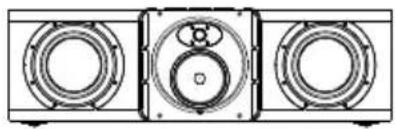
Technical line drawing of three identical mechanical components with circular cutouts and mounting holes (no text or symbols)CT8 CC
Description 3-way closed-box system
Drive Units 1x ∅32mm (1 14 in) metal dome high-frequency 1x ∅150mm (6 in) woven Kevlar® cone FST™ midrange 2x ∅250mm (10 in) Rohacell® cone bass
Frequency Range -6dB at 23Hz and 40kHz
Frequency Response 29Hz - 24kHz ±3dB on reference axis
Dispersion Within 2dB of reference response Horizontal: over 60° arc Vertical: over 10° arc
Sensitivity 93dB spl (2.83V, 1m) (mf/hf)
Harmonic Distortion 2nd and 3rd harmonics (90dB, 1m) <1% 45Hz – 20kHz <0.5% 55Hz – 20kHz
Nominal Impedance 8Ω (minimum 4Ω)
Crossover Frequency 300Hz, 4kHz
Recommended Amplifier Power 500W - 1000W into 8Ωon unclipped programme
Max Recommended 0.1Ω Cable Impedance
Dimensions Height: 325mm (12.8 in) (without spike feet) Width: 1100mm (43.3 in) Depth: 550mm (21.65 in)
Weight 85kg (187 lb)
natural_image
Technical line drawing of a multi-tiered speaker tower with three speakers and a circular base (no text or symbols)CT8 DS
Description 3-way monopole/2-way dipole selectable closed-box surround system
Drive Units 1x ∅32mm (1 14 in) metal dome high-frequency 6x ∅100mm (4 in) midrange/high-frequency 1x ∅150mm (6 in) woven Kevlar® cone FST™ midrange 2x ∅250mm (10 in) Rohacell® cone bass
Frequency Range -6dB at 26Hz and 40kHz (monopole mode) -6dB at 26Hz and 22kHz (dipole mode)
Frequency Response 31Hz - 22kHz ±3dB on reference axis (monopole mode) 31Hz - 18kHz ±3dB power averaged over front hemisphere (dipole mode)
Dispersion Monopole mode: Within 2dB of reference response Horizontal: over 60° arc Vertical: over 10° arc Dipole mode: horizontal figure of eight Effective null zone ±30° (250Hz – 18kHz)
Sensitivity 93dB spl (2.83V, 1m) (mf/hf)
Harmonic Distortion 2nd and 3rd harmonics (90dB, 1m) <1% 45Hz - 20kHz
Nominal Impedance 8Ω (minimum 4Ω)
Crossover Frequency 300Hz and 4kHz (monopole mode) 300Hz (dipole mode)
Recommended Amplifier Power 500W - 1000W into 8Ωon unclipped programme
Max Recommended 0.1Ω Cable Impedance
Dimensions Height: 1100mm (43.3 in) (without spike feet) Width: 325mm (12.8 in) Depth: 250mm (9.85 in)
Weight 75kg (165 lb)
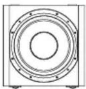
CT8 SW
Description Closed-box subwoofer
Drive Units 1x ∅380mm (15 in) carbon fibre/Rohacell® sandwich cone bass
Frequency Range -6dB at 13Hz and 40Hz
Frequency Response 18Hz - 35Hz ±3dB on reference axis
Dispersion Within 2dB of reference response
Horizontal: over 90° arc
Vertical: over 90° arc
Sensitivity 90dB spl (2.83V, 1m) (mf/hf)
Harmonic Distortion 2nd and 3rd harmonics (90dB, 1m)
<1% 30Hz - 500Hz
<0.5% 45Hz - 300Hz
Nominal Impedance 8Ω (minimum 4Ω)
Crossover Frequency 40Hz
Recommended Amplifier Power 50W - 1000W into 8Ω on unclipped programme
Max Recommended 0.1Ω
Cable Impedance
Dimensions Height: 475mm (18.7 in) (without spike feet)
Width: 475mm (18.7 in)
Depth: 475mm (18.7 in)
Weight 35kg (77 lb)
CT8 XO Mk 2
Description CT800 system active bass management controller
Functions Bass/midrange crossover
Subwoofer/bass crossover
Low-frequency roll-off alignment
High frequency roll-off alignment
3 parametric equalisers
Subwoofer in/out
Level adjustment for number of subwoofers
12V trigger switching for surround mode
Inputs Line In (XLR)
12V trigger (3.5mm jack)
Outputs MF/HF Line Out (XLR)
LF Line Out (XLR)
Subwoofer Line Out (2 x XLR)
12V trigger (3.5mm jack)
Rated power consumption 20W
Dimensions Height: 44.5mm (1.75 in) 1U
Width: 483mm (19 in)
Depth: 155mm (6.1 in)
Weight 3kg (6.6 lb)
B&W Bowers & Wilkins
B&W Group Ltd.
Dale Road
Worthing West Sussex
BN11 2BH England
T +44 (0) 1903 221 800
F +44 (0) 1903 221 801
info@bwgroup.com
www.bowers-wilkins.com
B&W Group (UK Sales)
T +44 1903 221 500
E uksales@bwgroup.com
B&W Group North America
T +1 978 664 2870
E marketing@bwgroupusa.com
B&W Group Asia Ltd.
T +852 2 869 9916
E info@bwgroup.hk
Kevlar is a registered trademark of DuPont.
Nautilus is a trademark of B&W Group Ltd.
Copyright © B&W Group Ltd. E&OE
Printed in China.