
KQ45XE - Basket SMEG - Free user manual and instructions
Find the device manual for free KQ45XE SMEG in PDF.
User questions about KQ45XE SMEG
0 question about this device. Answer the ones you know or ask your own.
Ask a new question about this device
Download the instructions for your Basket in PDF format for free! Find your manual KQ45XE - SMEG and take your electronic device back in hand. On this page are published all the documents necessary for the use of your device. KQ45XE by SMEG.
USER MANUAL KQ45XE SMEG
11aBBP Tasselli SS INPTNbl
BBQ.tyBBSocumentablioneB
USCITJIbJIrIRbVERSIONEeFILTRJINTEB
RECOMMENSIATIONSBJINSBSUGGESTIONS
The Instructions for Use apply to several versions of this applianceE AccordinglyO y descriptions of individual features that do not apply to your specific applianceE
INSTILLLITIONB
The manufacturer will not be held liable for any damages resulting from incorrect or improper installationE
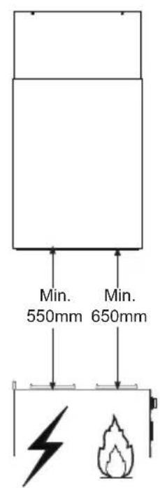
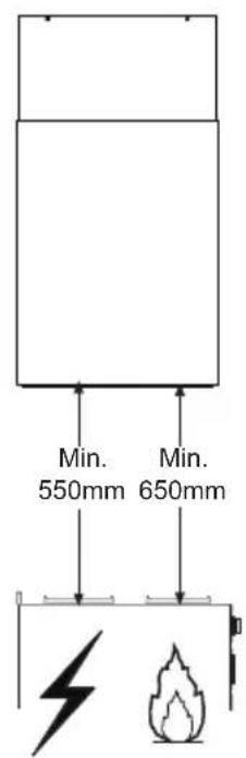
The minimum safety distance between the cooker top and the extractor hood is mm (some models can be installed at a lower height 0 please refer to the paragraphs on working dimensions and installation)E
Zheck that the mains voltage corresponds to that indicated on the rating plate fixed to the inside of the hoodE
For Zlass I appliancesO check that the domestic power supply guarantees adequate earthingE Zonnect the extractor to the exhaust flue through a pipe of minimum diameter IPbI mmE The route of the flue must be as short as possibleE
Do not connect the extractor hood to exhaust ducts carrying combustion fumes (boilersO fireplacesO etcE)E
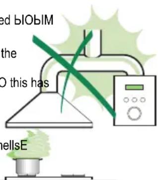
If the extractor is used in conjunction with nonBelectrical appliances (eEgE gas burning appliances)O a sufficient degree of aeration must be guaranteed in the room in order to prevent the backflow of exhaust gasE The kitchen must have an opening communicating directly with the open air in order to guarantee the entry of clean airEBWhen the cooker hood is used in conjunction with appliances supplied with energy other than electricO the negative pressure in the room must not exceed bIObIM mbar to prevent fumes being drawn back into the room by the cooker hoodE
In the event of damage to the power cableO it must be replaced by the manufacturer or by the technical service departmentO in order to prevent any risksE
If the instructions for installation for the gas hob specify a greater distance specified aboveO this has to be taken into accountE Regulations concerning the discharge of air have to be fulfilledE
USEB
The extractor hood has been designed exclusively for domestic use to eliminate kitchen smellsE
念 Never use the hood for purposes other than for which it has been designedE
Never leave high naked flames under the hood when it is in operationE
Adjust the flame intensity to direct it onto the bottom of the pan onlyO making sure that it does not engulf the sidesE
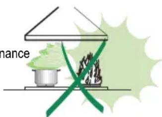
Deep fat fryers must be continuously monitored during useY overheated oil can burst into flamesE
Do not flamby under the range hood3 risk of fire
This appliance is not intended for use by persons (including children) with reduced physicalO senB sory or mental capabilitiesO or lack of experience and knowledgeO unless they have been given suB pervision or instruction concerning use of the appliance by a person responsible for their safetyE
Zchildren should be supervised to ensure that they do not play with the applianceE
" ZAUTIONy Accessible parts may become hot when used with cooking appliancesE"E
MJINTENJNCEB
Switch off or unplug the appliance from the mains supply before carrying out any maintenance workE
Zlean andTor replace the Filters after the specified time period (Fire hazard)E
Zlean the hood using a damp cloth and a neutral liquid detergentE
The symbol on the product or on its packaging indicates that this product may not be treated as household waste. Instead it shall be handed over to the applicable collection point for the recycling of electrical and electronic equipment. Syensuring this product is disposed of correctly you will help prevent potential negative consequences for the environment and human health which could otherwise be caused by inappropriate waste handling of this product. Form more detailed information about recycling of this product please contact your local city office your household waste disposal service or the shop where you purchased the product
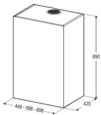
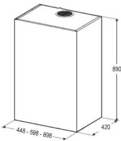
DimensionsB
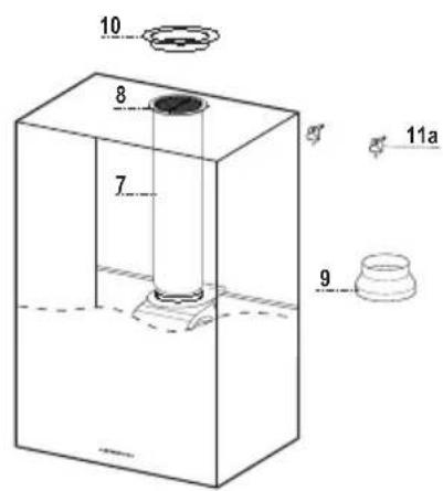
Components
Ref.BBBQ.tBbbbProductbcomponentsb
1B Hood Sody complete with Y ZontrolsO LightO Suction UnitO FiltersO Lower Duct
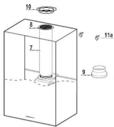
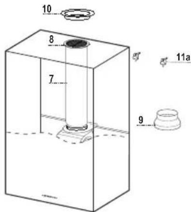
7 IV PVZ Pipe (fitted)
8 Inclinable grid (fitted)
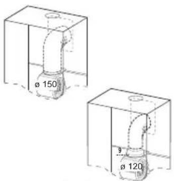
9 U Reduction flange 0 HbIBPbl mm
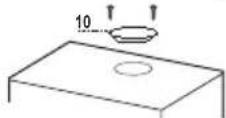
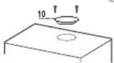
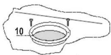
10 U Metal cover
Ref.BBQ.tBBJssemblBbcomponentsb
11a P S S NPTNbl Plugs
Q.tBBBDocumentsB
V Instruction Manual
boringBtheBCallB
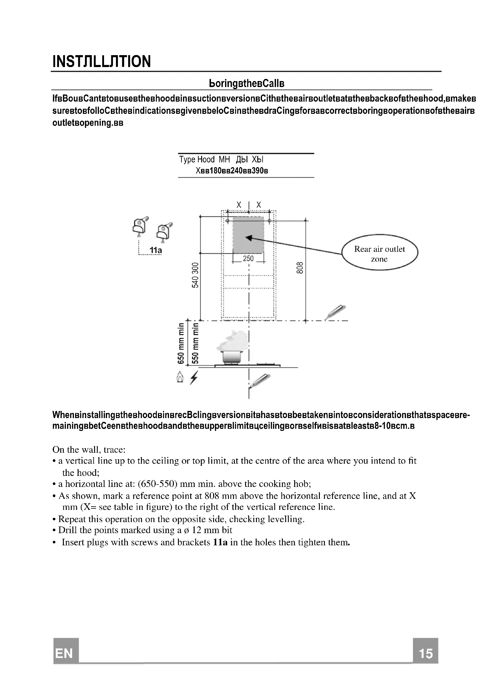
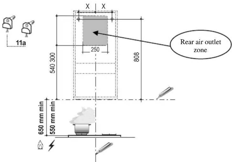
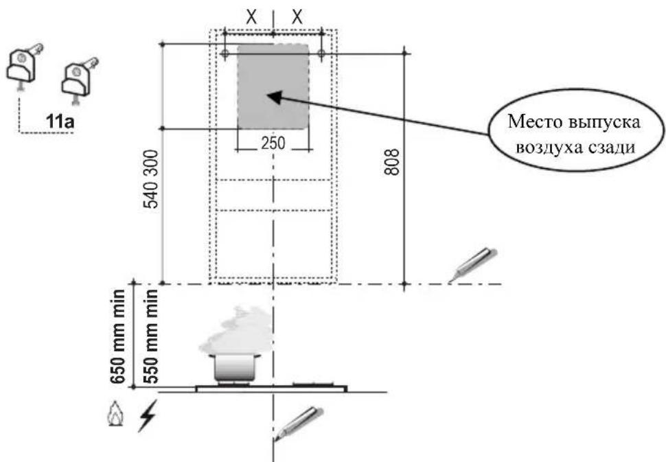
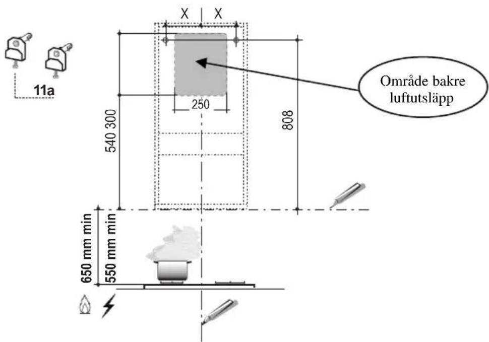
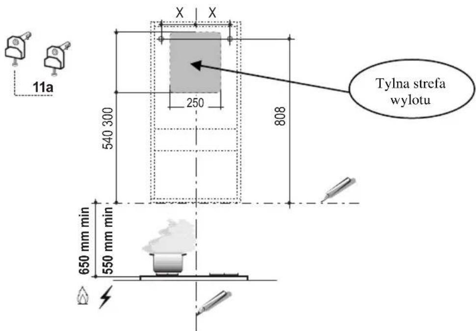
IfBouB CantBtoBuseBtheBhoodBinB suctionBversionBCithBtheBairBoutletBatBtheBbackBofBtheBhood,BmakeB sureBtobfolloCtheBindicationsBgivenBbeloCbinBtheBdraCingBforBaBcorrectBoringBoperationBofBtheBairBoutletBopening.BB
Type Hood MH Dbl Xbl XBB180BB240BB390B
WheninstallingthehoodbinBrecBclingBversionBitbhasBtobbeBtakenBintoBconsiderationBthatbspaceBre- mainingbbetCeenBthehoodBandBtheBupperBlimitBceilingBorbselfbisBatBlast8-10Bcm.B
On the wall, trace:
- a vertical line up to the ceiling or top limit, at the centre of the area where you intend to fit the hood;
- a horizontal line at: (650-550) mm min. above the cooking hob;
- As shown, mark a reference point at 808mm above the horizontal reference line, and at X mm (X = see table in figure) to the right of the vertical reference line.
- Repeat this operation on the opposite side, checking levelling.
- Drill the points marked using a 12mm bit
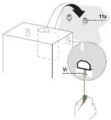
- Insert plugs with screws and brackets 11a in the holes then tighten them.
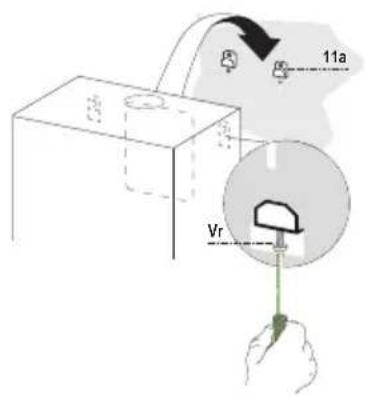
HoodBbodBbassemlBb
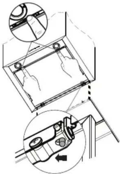
- Adjust the two screws Vr of brackets 11a, by just placing them in position.
- Hook the hood body to the two brackets 11a.
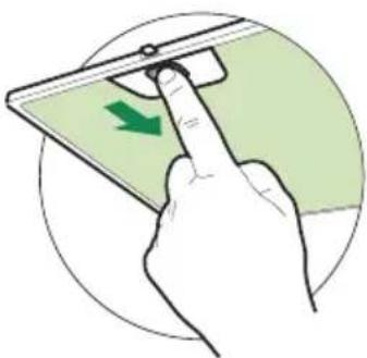
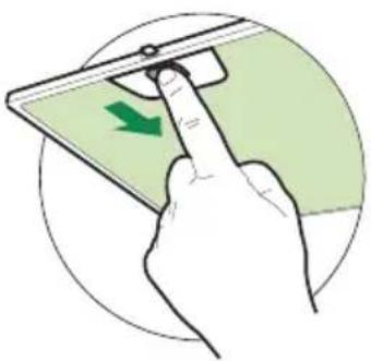
- Pull the Comfort Panel to open it, remove the filters one by one, push them towards the rear part of the unit and pull downwards at the same time.
- From inside the hood body, tighten the screws Vr to level the body.

ConnectionB
JIRBOUTLETBINBJSUCTINGBHOOSbVERSIONs
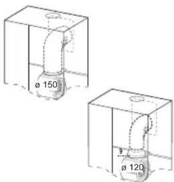
When installing the hood in ducting version, basing on the installer's choice, a rigid or a flexible pipe with a 150 or 120mm is used in order to connect the hood to the air outlet piping. The pipe connection can be made on the upper part or on the rear side of the hood.
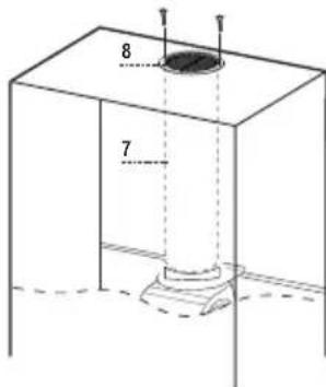
Before connecting the hood to the air outlet ducting remove the lateral air outlet grid 8 and the plastic tube 7. The adapting flange 9 has to be removed only in case the connecting diameter is 150.
REAR AIR OUTLET
- When drilling the air outlet hole in the wall proceed in accordance with the scheme in the part concerning the wall drilling.
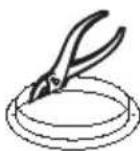
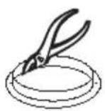
- Use a pair of tongs when breaking the rear air outlet hole in the wall.
- In case the connection is made by using a 120mm pipe insert the reduction flange 9 on the hood body outlet.
Fix the pipe with an adequate quantity of pipe clamps. This material is not supplied together with the hood. - Remove the charcoal filter if present.
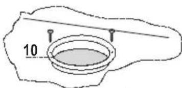
Fix the metal cover 10 to the upper air outlet hole of the hood by using the screws supplied.
UPPER AIR OUTLET
- In case the connection is made by using a 120mm pipe insert the reduction flange 9 on the hood body outlet.
- Use a pair of tongs when removing the central part of the metal cover 10. Fix the cover to the air outlet hole of the hood by using the screws supplied.
Fix the pipe with an adequate quantity of pipe clamps. This material is not supplied together with the hood. - Remove the charcoal filter if present.


JIRBOUTLETBINJBRECYCLINGBHOOSBVERSIONB
- In case the components requested for the recycling functioning have been removed earlier these have to be positioned again.
- Put the plastic tube onto the flange 7.
- Place the air outlet grid 8 on the air outlet. Make sure that the position of the grid is correct.
- Make sure that charcoal filters have been placed inside the hood.

ELECTRICJLBCONNECTION8
- Connect the hood to the mains through a two-pole switch having a contact gap of at least 3mm .
- Remove the grease filters (see paragraph Maintenance) being sure that the connector of the feeding cable is correctly inserted in the socket placed on the side of the fan.

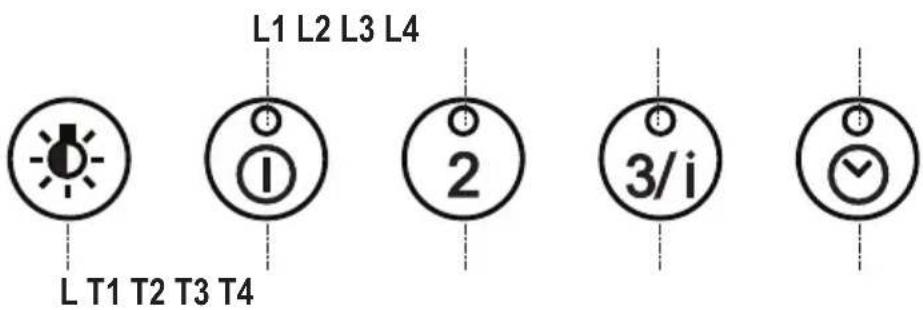
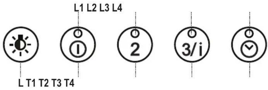
ControlbpanelB
| But ton | Function Led | |
| L Turns the lighting system on and off. - | ||
| Press and hold for approx. 2 seconds to turn the lighting system on and off at reduced intensity. | - | |
| T1Turn the suction motor on and off at speed one. On. | ||
| Press and hold the button for approximately 2 seconds, with all the loads turned off (Motor and Lights), to reset the Filters and turn off the LEDs that are lit. | After 100 working hours all the LEDs (L1-L2-L3-L4) will light up and remain lit to indicate saturation of the metal grease filters. After 200 working hours all the LEDs (L1-L2-L3-L4) will light up and start to flash to indicate saturation of the activated charcoal filters. | |
| T2Turn the suction motor on at speed two. On. | ||
| Press and hold for approximately 5 seconds, with all the loads turned off (Motor and Lights), to enable/disable the Remote control. | 2 flashes, Remote control Enabled. 1 flash, Remote control Disabled. | |
| T3Turn the suction motor on at speed three. On. | ||
| Press and hold the button for 2 seconds to activate intensive speed. This speed is timed to run for 10 minutes. At the end of this time the system will automatically return to the speed set before. | ||
| T4Press and hold the button for approximately 2 seconds to activate automatic shutdown with a 30' delay (Motor+Lights). | On. | |
| Press and hold for approximately 5 seconds to enable/disable the Activated Charcoal Filter alarm. | 2 Flashes of the LEDs (L1-L2-L3) Filter Alarm Enabled. 1 Flash of the LEDs (L1-L2-L3) Filter Alarm Disabled. | |
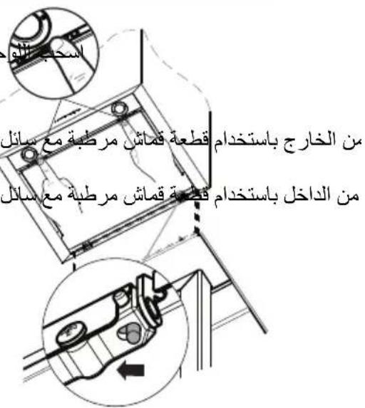
CleaningBtheBComfortBPanelsb
- Pull the Comfort Panel to open it.
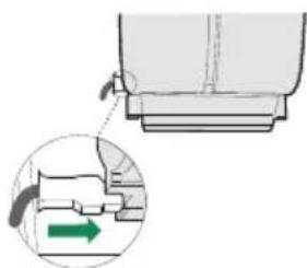
- Disconnect the panel from the hood canopy by sliding the fixing pin lever.
- The comfort panel must never be washed in a dishwasher.
- Clean the outside by using a damp cloth and neutral liquid detergent.
- Clean the inside as well by using a damp cloth and neutral detergent; do not use wet cloths or sponges, or jets of water; do not use abrasive substances.
- When the above operation has been completed, hook the panel back to the hood canopy and close it by turning the knob in the opposite direction.
Metalbgreasebfilters
These can also be washed in the dishwasher, and need to be cleaned when all the command LEDs light up in a continuous manner or at least once every 2 months use, or more frequently if use is particularly intensive.
Resetting the alarm signal
- Press button T1 (see the paragraph on Use).
Cleaning the Filters
- Pull the Comfort Panels to open them.
- Remove the Filters one at a time, pushing them towards the back of the unit and at the same time pulling downward.
- Wash the Filters without bending them, and leave them to dry completely before replacing.
- Replace, taking care to ensure that the handle faces forwards
- Close the comfort panels.
JNctivatedBCharcoalBFilterBucRecirculationBVersionNB
- This cannot be washed or regenerated, and must be changed when all the command LEDs start to flash, or at least once every 4 months.
Activating the alarm signal
- In Recirculation Version Hoods, the Filter Saturation Alarm must be activated on installation or at a later date.
- Press and hold the Delay button (T4) on the keypad for 5 seconds and the following will be displayed:
- Leds (L1-L2-L3) flash twice - Activated Charcoal Filter saturation alarm ACTIVATED.
- Leds (L1-L2-L3) flash once - Activated Charcoal Filter saturation alarm DEACTIVATED.
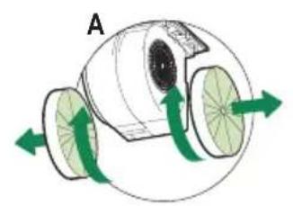
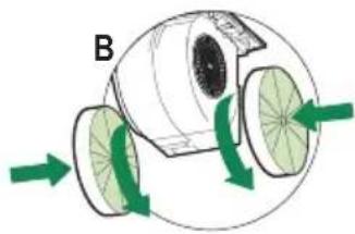
CHJINGINGBTHEBJCTIVTESBCHJRCOJLBFILTER
Resetting the alarm signal
- Press button T1 (see the paragraph on Use).
Changing the Filter
- Pull the Comfort Panels to open them.
- Remove the Metal grease filters.
- Remove the saturated Activated Charcoal Filters, as indicated (A).
- Fit the new Filters, as indicated (B).
- Replace the Metal grease filters.
- Close the comfort panel.s
LightingB
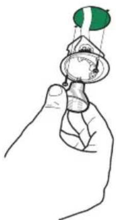
LIGHTBREPLICEMENTB
20 W halogen light.
- Remove the 2 screws fixing the Lighting support, and pull it out of from the Hood.
- Extract the lamp from the Support.
- Replace with another of the same type, making sure that the two pins are properly inserted in the lamp holder socket holes.
- Refit the Support, fixing it in place with the two screws removed as above.
NettoBageBdesBConfortBPanelB
REEMPLJCEMENTBLJMPESB
JUSWECHSELNBSERBLJMPENB
Halogenlampe 20 W
11aBBP Tacos S S NPTNbl
Cant.BB.SocumentaciINb
CONSELHOSBEBSUGESTOESB
Estas instruexes de servio aplse a variedos modelos dkarelhos
CmBn HnHnHnHa eOyNkOBe yBaAeT,HTOHO He nDTRNTYTNKALIM B KHeCTBe 508xOxOxOB.BMeTO storo 1000000000000000000000000000000000000000000
npabnla ytnin3aun n3denny,Bbl noomoxete npedotbpaTntb npnHHeHne okpykaioe cpe n 3doPobBoIOIOe noTeHuaIbHoruepB, KTOptb BcMOHN, B pOTHINOM OYae, BCNEPTWE HnppoAoJero obaueHm C nppboHM OTxqam. 3a 60nee
noipro6Hn HnΦopMaueH nO yTNIN3aunm 3TOrO n3JeIINn npoc6ba oBpaatbck K MeCTbIM BnactrM, B CnyKbY nOBBOy nYTNIN3aUNn OTXoOB INB Maar3HN, B KOtOpom Bbl pniO6pei n3dene.
T6apntbI
Yactn
06. Kon. Yactn n3dennr
1 1 Kopnyc BbITJIKN B KOMJIeKTe C yCTpOiCTBaMn ynpaBJIeHn,OCBeUeHnEM,BEHTIJIrTOPOM, FNJIbTpAMn,HxKHe YacTbIO DblMOXoJa
71 Tpy6ka n3 PBX (ycTaHOBJeHa)
81 PerynpyempeWetka (ycTaHOBHeHa)
91 IepexoHbI cPnaHeu 150-120 MM
10 1 3aRnyuka
06. Kon. YctaHOBOUHbIe KOMNoHeHTbI
11a 2 Bknaabbiu SB 12/10
KoI. DOKyMeHTaUra
1 PykoBoDCTBO no 3KcnIpyTaun
OTBepctn B cteHe
IpnKeJAHNN NOKNIUHTb BCacbIBaIOUyO BbITXkky TaK, YTO6bl Tpy6a BbIXoHnA C3aHn np6opa, OTBepCTne IINr OTBeHnB BO3dyxA DOJXHO 6blcDeJaHO B COOTBeTCTBmC npNBeEHhIMn Ha pncyHke yKa3aHnAMn.
TIN BBITAKK 45 60 90
X 180 240 390
B cnyae yctaHOBN fNJIbTpUoSeB bITJXKN CJeDyET NMeTb B BVdy, YTO MExdy np6Opom n BepxHm npedeJOM (nOTOnOK nIN NOBecHa JONka) DOJXHO 6bITb paCCTOAHne He MeHee 8-10 CM.
PpOBecTHHaCTeHe:
BepTHKaJIbHyIO JINHHIO IO IIOTOJka HJN IO BepXHeRo IIpeJeJa IIO ueHTpy yUactKa, IIpeIHa3HaueHHOrO IJIy YCTaHOBKn BblTgKK;
- Trop30HTaJIbHyIO JInHHIO Ha pacCToRHH He MeHee (650-550) MM HAd IJIHToI.
OTMeHTb, KaK yKa3aHO, yCTaHOBOUHyIO TOUky Ha paccToHHN 808 MM NaI rOpH3OHTaJIbHOJ JHHNe H Ha paccToHHN X MM (X - cMOTpH IIpHBeDEHHyIO Ta6JIHUY) cIpaBa OT BepTHKaJIbHOJ JHHN.
IIOBTOPTb 3Ty OIIepaHIO C IIpoTHBOIOJIOKeHHOHTOPHOBePTHKaJIbHOJINHHN H IPOBEPHTb, YTO6bI TOCKI 6blHN Ha ODNOM yPOBHe.
IocBepJIHTb OTBepCTHg 12 MM B O6O3HaueHHbIX TOUkax.
BCTaBHtB BKJaIbHmC BNHTOM n cKo60n 11a B OTBepcTHn H 3aBHHTtBHX.
YctaHOBKa Kopnyca BbITXKN
BCTaBHTb IBa BnHTa Vr cko6 11a B HcxOHOe IOJIOKeHHe.
- IOBecHTb KOpIYc BbITJxKHa 2 cKO6bl 11a.
- IOTaHyb Ha ce6n OTKpbTb NpeHIO HnHeJIb, nO oupeHN BbHyb FnJIbTpbl. JIy 3TOrO npKaTb nx K 3aHHei cSTOPoHE BbITKKN OIOHOBpeMeHHo HaJABHTb BHN3.
- H3HyTpH KOpIyCa BbITJIKKIOptepRyJIINPOBaTb 3aTAKKY BnHTOB Vr, yTO6bI BBICTaBNTb eO IO ypOBHIO.
CoeHHnHeHn
BbIyCK BO3DyXA I3 BCACbIBAOUEN BbITJAKKIN
Для установки BCacbIBaIOшeи BBITJxKn COeINHHTb ee C BblnyckHOI Tpy60J KecTKOJ HIN rH6KOJ Tpy6ko J 150 HJIH 120 MM IIO yCMOTpeHHIO MOHTaXHHka. Tpy6Ka MoKeT BbIXOJNTb KaK CBepxY, TaK N c3aJIN BBITJxKn.
IpejE He m IpnctyHnTb K coeHHeHIO BcacBbAIOue Tpy6bl, yJaHTb peYJnpyeMyIO peIIETKy 8 n Tpy6ky 7 H3 IIBX, ecJN OHn eHtBi. IepexoIHbI JaHeu 9 cJeIyET BbHyTB TOJIbKO JIA coeINHeHn Tpy6Kn 0 150.
BbIIYCK BO3JYXA C3AJI
- YTO6bI cJIeJIaTb OTBepCTHe IJIa OTBeJIeHn BO3JyXa, cJIeIyET IIpIIePJIbBaTbCra CXeMbI, IIpINBeJIeHHoB B pa3JIeJIe "OTBepCTHn B CTeHe".
KJIeIaMNIOTKpbITb3aIHcBbIIYCKHOcOTBCpCTHe BO3JyXa.
-Дя coeHHeHЯ c Tpy6koJ 0 120 MM BCTaBHTb IepexOHNbI ΦJaHeu 9 B BBInyCKHOE OTBepCTHe KOpIYCa BBITRAKKN.
3aKpeHbT py6ky cIeHaJIbHbIMN Tpy6hBMn 3aKHMamH. Heo6XOJIMbI MATEpHaJI He BXOJNT B KOMIIJEKT IOCTaBKn.
EcJH eCTb, BbIHyTb 0HJIbTpbl IIpOTHB 3aIIaxOB Ha aKTHBHom VrJIe. - YcTaHOBtB 3aRJyIiKy 10 Ha BepXHEM BbIYCKHOM OTBepCTHN BBITAKKII pNJJaRaEMbIMN BHHTAMH.
BbITYCK BO3DUXA CBEPXV
-Для coeHHeHnC Tpy6koJ 0 120 MM BCTaBHTb IepexOHNBII ΦlaHeu 9 B BbIyCKHOE OTBepCTHe KOpHyCa BbITaKKn.
KJIeIaMn BbIHytb IeHTpaJbHyIO qAcTb 3aRJyIKN 10 H 3aKpeIHTb ee Ha BepXHEM BbIYcKHom OTBepCTHN BBITJxKKH IIpNJIraembIMN BIHTAMN.
3aKpeHbT py6ky cneuaJIbHbIMN Tpy6hIMN 3aKHMAMn. Heo6xoHMBI MaTePnaJI He BXOHT B KOMIIJEKT IOCTaBKN.
- EcJH eCTb, BbIHyTb ΦHJIbTpbl IpOTHB 3aIIaxOB Ha aKTHBHom yrJIe.


BbIyCKBBO3dYXAbN3bΦINbTPYIOeINBbITJXKNB
- EcJH H3 9nJIbTpYIOUeB bITJXKN CHrTbI paHee yCTaHOBJEHHbIE ee YactN, NOCTaBHTb IX Ha MeCTO.
BCTaBHTb Tpy6ky H3 INX 7 BO fJAnaHeI. - IIpNBHTnB peRyJnpyeMyIO peIeTKy 8 K BbIyCKHOMY OTBepCTNHO BO3JyXa H IpoBepNTb ee NOJIOKeHHe Ha Tpy6Ke.
- IIpoBepHTb HaJIHcHe _HJIbTPOB IIpOTHB 3aIIaxOB Ha aKTHBHOM yTJIe.
3NEKTPNUECKOEbNOJKNIOUOHENB
CoeHHHTb BBITKky c ceTeBBIM HaIIpyKeHHem, yCTaHOBHB BByXIOJIIOCHbI BbIKJIOHaTeJIb C pa3BeJeHHem KOHTaKTOB He MeHec 3 MM.
CHrTB IPOTHBOXHHPOBbIe HJIbTpBI (cMOtpn pa3JeT "YxoJ") H IPOBcPHTb IIpaBNJIbHOCTb IOJOKeHHra pa3bema IITaHOIIeRo Ka6eJI B pO3ETKE BBITJIKN

PanaheIb ynpaBneHnA
Ref.88IntalBbInstallationskomponents
11a P Expansionspluggar SS NPTNbl
JntalbbSokumentationsB
V Sruksanvisning
börningBivveggB
OmbdubvllbanslutaBkΦksflektenBibutsugandebversion,BgenombattblhtabrΦretbkommaButBpHbbaksidan,B kombihhgbattluftensBevakueringshlbskaBgΦrasbenligtBanvisningarnabpHbefterfΦljandeBritting.B
Kbksfloktstyp MH Dbl Xbl
XBB180BB240BB390B
VidinstallationBavbkΦksflektenBibfilterandebversion,BtabhensBnBtill,BattbΦverbkΦksflekten,BmHsteBettB avsthndBfrhNbΦvreBgrensenButakBellerBkonsolNBpHbMinstBB8-10cmbkvarstn.B
Markera pa väggen:
RengΦringBavBConfortpanelB
MocoCanieBdoBscianBb
JbBbpodlacblBcBbokapBBCb CersjbbblcBciagiem,BbrurabCBchodblaCappoCinnabBcBbpoproCad tBlnej sianB,b ab otCUrB poCietrlab CBchodblacegoB poCinienb BcB CBkonanBb Cedlugb ponizrBsunku.B
TBpBokapubBB45BBB60BB90B XBB180BB240BB390B
a a a a a a a a a a a a a a a
Jus
Ee 1
E
E 1
Ea
Eckydi jolldjil 1d lalac dcll aoll klo
EysollisAisslalniy
J 1
j 1
FioXu
E
"Ee 4
aill
1
()
Ea
12 = 11,9cbibj
aaii aai i 1
cblb w j (650-550) aLw g h
X 808 808 808
15 1
a 12
11a 1
e bll
11a 11a 11a
#
jieiiee jie1g
a 100 120 150 150
8 100 100 100
9 7 7 7
.150
j 1
jglal g jg jdl glall. 10
g j 9 120
g j 10 1j
.
.
.
.
e 1
.
- 8
7
y
()
a aal
ylll llll 10n 519 (aillll jjbj) jil jil
aagall gie gao gao aaii jia

A
| الصعndefी الإستعمال | الإستعمال | |
| - | الإستعمال | L |
| - | الإستعمال | 2 8 10 15 2 3 4 5 6 7 8 9 10 11 12 13 14 15 16 17 18 19 20 21 22 23 24 25 26 27 28 29 30 31 32 33 34 35 36 37 38 39 40 41 42 43 44 45 46 47 48 49 50 51 52 53 54 55 56 57 58 59 60 61 62 63 64 65 66 67 68 69 70 71 72 73 74 75 76 77 78 79 80 81 82 83 84 85 86 87 88 89 90 91 92 93 94 95 96 97 98 99 100 101 102 103 104 105 106 107 108 109 110 111 112 113 114 115 116 117 118 119 120 121 122 123 124 125 126 127 128 129 130 131 132 133 134 135 136 137 138 139 140 141 142 143 144 145 146 147 148 149 150 151 152 153 154 155 156 157 158 159 160 161 162 163 164 165 166 167 168 169 170 171 172 173 174 175 176 177 178 179 180 181 182 183 184 185 186 187 188 189 190 191 192 193 194 195 196 197 198 199 200 201 202 203 204 205 206 207 208 209 210 211 212 213 214 215 216 217 218 219 220 221 222 223 224 225 226 227 228 229 230 231 232 233 234 235 236 237 238 239 240 241 242 243 244 245 246 247 248 249 250 251 252 253 254 255 256 257 258 259 260 261 262 263 264 265 266 267 268 269 270 271 272 273 274 275 276 277 278 279 280 281 282 283 284 285 286 287 288 289 290 291 292 293 294 295 296 297 298 299 300 301 302 303 304 305 306 307 308 309 310 311 312 313 314 315 316 317 318 319 320 321 322 323 324 325 326 327 328 329 330 331 332 333 334 335 336 337 338 339 340 341 342 343 344 345 346 347 348 349 350 351 352 353 354 355 356 357 358 359 360 361 362 363 364 365 366 367 368 369 370 371 372 373 374 375 376 377 378 379 380 381 382 383 384 385 386 387 388 389 390 391 392 393 394 395 396 397 398 399 400 401 402 403 404 405 406 407 408 409 410 411 412 413 414 415 416 417 418 419 420 421 422 423 424 425 426 427 428 429 430 431 432 433 434 435 436 437 438 439 440 441 442 443 444 445 446 447 448 449 450 451 452 453 454 455 456 457 458 459 460 461 462 463 464 465 466 467 468 469 470 471 472 473 474 475 476 477 478 479 480 481 482 483 484 485 486 487 488 489 490 491 492 493 494 495 496 497 498 499 500 501 502 503 504 505 506 507 508 509 510 511 512 513 514 515 516 517 518 519 520 521 522 523 524 525 526 527 528 529 530 531 532 533 534 535 536 537 538 539 540 541 542 543 544 545 546 547 548 549 550 551 552 553 554 555 556 557 558 559 560 561 562 563 564 565 566 567 568 569 570 571 572 573 574 575 576 577 578 579 580 581 582 583 584 585 586 587 588 589 590 591 592 593 594 595 596 597 598 599 600 601 602 603 604 605 606 607 608 609 610 611 612 613 614 615 616 617 618 619 620 621 622 623 624 625 626 627 628 629 630 631 632 633 634 635 636 637 638 639 640 641 642 643 644 645 646 647 648 649 650 651 652 653 654 655 656 657 658 659 660 661 662 663 664 665 666 667 668 669 670 671 672 673 674 675 676 677 678 679 680 681 682 683 684 685 686 687 688 689 690 691 692 693 694 695 696 697 698 699 700 701 702 703 704 705 706 707 708 709 710 711 712 713 714 715 716 717 718 719 720 721 722 723 724 725 726 727 728 729 730 731 732 733 734 735 736 737 738 739 740 741 742 743 744 745 746 747 748 749 750 751 752 753 754 755 756 757 758 759 760 761 762 763 764 765 766 767 768 769 770 771 772 773 774 775 776 777 778 779 780 781 782 783 784 785 786 787 788 789 790 791 792 793 794 795 796 797 798 799 800 801 802 803 804 805 806 807 808 809 810 811 812 813 814 815 816 817 818 819 820 821 822 823 824 825 826 827 828 829 830 831 832 833 834 835 836 837 838 839 840 841 842 843 844 845 846 847 848 849 850 851 852 853 854 855 856 857 858 859 860 861 862 863 864 865 866 867 868 869 870 871 872 873 874 875 876 877 878 879 880 881 882 883 884 885 886 887 888 889 890 891 892 893 894 895 896 897 898 899 900 901 902 903 904 905 906 907 908 909 910 911 912 913 914 915 916 917 918 919 920 921 922 923 924 925 926 927 928 929 930 931 932 933 934 935 936 937 938 939 940 941 942 943 944 945 946 947 948 949 950 951 952 953 954 955 956 957 958 959 960 961 962 963 964 965 966 967 968 969 970 971 972 973 974 975 976 977 978 979 980 981 982 983 984 985 986 987 988 989 990 991 992 993 994 995 996 997 998 999 |
psill 1
jIbJI alluie Jld lyilg jSall 1Jue jay
S = S1 + S2 + S_3
y y 1
aIjoo
g lgl 1 glll jgsy gaaag aal
-
gaaa aee
jiaiill ojiil biaodjol
(1auii jai)T1jil bai
S OBC = S ABC + S_ CDF
LgSjisdle! 1s caii Ie jil gaii jia jidai Jie
4 Jd j 1 1 1 1 1 1 1 1 1 1 1 1 1 1 1 1 1 1 1
Jaeiui jno
y
aay aaii dll k jie al gaiy buiu jay jidall dlal jia jai dall
Delay (T4)
41211111111111111111111111111111111111111111
1