
100 GC - Welding machine Güde - Free user manual and instructions
Find the device manual for free 100 GC Güde in PDF.
| Product type | Inverter welding machine (INVERTER) |
| Model | 100 GC |
| Product number | 20055 |
| Power supply | 230 V ~ 50 Hz |
| Mains power | 3.2 kVA |
| Max. welding current | 100 A |
| Current adjustment range | 10 - 100 A |
| Open circuit voltage | 85 V |
| Recommended material thickness | 0.8 - 8 mm |
| Electrode diameter | 1.6 - 2.5 mm |
| Duty cycle (ED) at max current | 100 A ~ 15% |
| Duty cycle (ED) at 55 A | 60% |
| Duty cycle (ED) at 45 A | 100% |
| Insulation class | IP21S |
| Weight | Approx. 3.6 kg |
| Technology | High frequency inverter (>80 kHz) |
| Welding functions | MMA (stick welding) and WIG (TIG) with optional accessory |
| Overheating protection | Yes (thermal switch) |
| LED indicators | Fault indicator (overload or mains voltage out of range) |
| Warranty | 12 months industrial use, 24 months end consumer |
| Maintenance | Check cables and connections; replace damaged parts with original parts |
Frequently Asked Questions - 100 GC Güde
User questions about 100 GC Güde
0 question about this device. Answer the ones you know or ask your own.
Ask a new question about this device
Download the instructions for your Welding machine in PDF format for free! Find your manual 100 GC - Güde and take your electronic device back in hand. On this page are published all the documents necessary for the use of your device. 100 GC by Güde.
USER MANUAL 100 GC Güde
Original Operating Instructions
INVERTER
Français FR 15
that the following Appliance complies with the appropriate basic safety and health requirements of the EC Directive based on its design and type, as brought into circulation by us.
In a case of alternation of the machine, not agreed upon by us, this declaration will loose its validity.
Applicable EC Directives: - 2006/95/EC
Date/Authorized Signature:
!! Please read this instruction for operation carefully before putting the machine into operation !!!
A.V. 2 Surplus print even in shortened version requires permission.
Technical changes reserved. Illustrations used represent examples.
| GB | Do you have any technical questions? Claim? Do you need spare parts or instructions for operation? We are ready to help you quickly and without unnecessary bureaucracy at our site www.guide.com in the part Service. Please help us in helping you. In order to identify your machine in case of a claim we need its serial number, product number and year of production. All the data mentioned can be found at the type plate. Please write them down bellow to have them always handy: Serial number: Product number: Year of production: | ||
| Phone.: +49 (0) 79 04 / 700-360 | Fax: +49 (0) 79 04 / 700-51999 | E-Mail: support@ts.guide.com | |

Given unfavourable conditions in the power supply the equipment may cause the voltage to drop temporarily. If the impedance "Z" at the connection point to the public power supply exceeds 0,233 Ω EN 61000-3-11 it may be necessary to take further measures before the equipment can be used as intended from this power supply. If necessary, you will ask your local electricity supply company for the impedance value.
Warranty
A warranty period of 12 months applies to commercial use and 24 months apply to private use and commences on the day of purchase of the device.
Warranty applies exclusively to failures due to defective material or workmanship. An original sale slip with indication of date of sale must be presented in case of claiming for the warranty rights.
Warranty does not cover unprofessional use such as device overload, violent use, damage caused by third party or foreign materials, failure to comply with operations and assembly manual, and normal wear and tear.
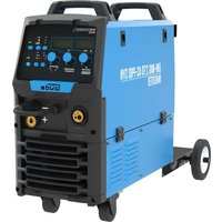
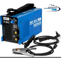
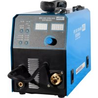
Device
figure 1/8
- Welding
current
controller
- Ground cable (-)
- Electrode cable (+)
- Main
Technical Data
Ordering No. 20055 INVERTOR 100 GC
| Supply voltage 230 V~50 Hz | |
| Mains power 3,2 kVA | |
| Minimum Protection 16 A | |
| Maximum welding current 100 A | |
| Idling voltage 85 V | |
| Recommended thickness of material | 0,8-8 mm |
| Electrodes 1,6-2,5 mm | |
| Range of control 10-100 A | |
| Switching time at maximum current | 100A~15% / 55A~60% / 45 A~100% |
| Protection class IP21S | |
| Approximate weight | 3,6 kg |
Ordering No. 20046 INVERTOR 140 GC
| Supply voltage 230V~50 Hz | |
| Mains capacity 4,7 kVA | |
| Minimum protection | 16 A |
| Idling voltage | 80 V |
| Recommended thickness of material | 0,8-12 mm / WIG 0,5-2mm |
| Electrodes | 1,6-4 mm |
| Range of control 20-140 A | |
| Start time at maximum current | 140 A~30% / 100 A~60 % / 90 A~100% |
| Insulation class | H |
| Protection class IP21S |
Approximate weight 6 kg
Ordering No. 20053 INVERTOR 160 GC
| Supply voltage 230 V~50 Hz | |
| Mains capacity 5,6 kVA | |
| Minimum protection 16 A | |
| Idling voltage 80 V | |
| Recommended thickness of material 0 | 8-15 mm / WIG 0,5-2 mm |
| Electrodes 1,6-4 mm | |
| Range of control 20-160 A | |
| Start time at maximum current 160 A~20 % / 100 A~60 % / 90 A~100 % | |
| Insulation class H | |
| Protection class IP21S | |
| Approximate weight 7 kg | |
General Safety Measures
It is essential to read the entire operation manual prior to the first use. If there are any doubts arising regarding connection and operation of the device, consult the manufacturer (servicing department).
Protect the device against moisture, rain and dust.
TO PROVIDE FOR MAXIMUM SAFETY, FOLLOW CAREFULLY THE INSTRUCTIONS BELOW:
The user shall be held liable for professionally done installation and for use of the machine in conformity with the manufacturer's data. If the user detects any electromagnetic faults, he is responsible for removing the same and use of the manufacturer's technical assistance. In many a case, just grounding the welding area is sufficient to remove the troubles. There are yet other cases, when developing an electromagnetic screen to cover the current source and the entire working area with a connected voltage filter may be helpful. In any case, the electromagnetic faults have to be removed so that they are not disturbing the user any more.
Caution: For the sake of safety, the current circuit should not be grounded. Any alteration of the grounding system should be done by competent authorised personnel able to estimate the consequences and risks of the alterations done.
Location Requirements
Prior to installation and starting the machine up, the user should account for any possible electromagnetic faults in the area.
The factors listed below should be taken into account:
a) other supply, control, signalling and telephone cables above the welding machine and under it and also in the adjacent area
b) radio and TV sets, receivers;
c) computers and other control equipments;
d) safety and monitoring instruments;
e) condition of health of those present, e.g. pacemakers, hearing aids etc.
f) meters used for calibrations;
g) protection of the other instruments and devices in the welding machine area. These devices should be compatible. Supplementary protection measures may be required.
h) Daytime, in which welding or other works are to be performed.
The area that may produce effects on the welding machine operation is subject to the building structure and other activities being carried out at a time of welding. The area may be as large as to near the neighbouring buildings.
Emission Reduction
Source Current Supply
As instructed by the manufacturer, the welding machine must be connected to the source current supply. If faults occur, it will be apparently necessary to provide for supplementary protective measures, such as a filter installed on the lead. The current leads of fixed welding machines should be protected with an insulation tube along the entire length of the cable. Welding cable should be as short as possible.
Special Safety Regulations
Introduction
The arc welding machines were developed thanks to many-year experience in the welding profession. Provided that the methods of operation prescribed by the manufacturer are provided, they will guarantee a high level of operating safety in addition to very good welding properties. For this reason, the management should take care to ensure that every person working with the machine has access to this information.
General Precautions
Protection against Burns
Sparkles, clinker, hot metal and radiation may be a serious hazard in arc welding putting eyes and skin at risk. The closer is the user or another person to the welding site, the bigger is the hazard they are exposed to. The user and any other persons working
adjacently to the welding site should wear adequate protective clothing and personal protective equipment. Protective gloves (special gloves for welding) and a headgear are indispensable. Goggles are essential and must be worn to protect the user's eyes against radiation, sparkles and hot metal.
Fire Protection
As hot metal, sparkles and clinker are generated by arc welding; precautions must be taken to prevent fire and explosions. Suitable fire extinguishers must be available in the area of welding site and any fire-hazardous materials should be removed from the area. The minimum distance of such materials from the welding area should be 10 metres (35 feet). Never weld empty tanks that contained toxins or explosives. Such tanks have to be cleaned very thoroughly before welding.
Never get down to welding if there are high concentrations of dust, easily inflammable gases and fire-hazardous vapours from liquids (such as petrol) in the atmosphere/air. Having completed the welding job, take care to cool down the welded parts before anybody could touch them or before they are in contact with fire-hazardous or ignitable materials.
Toxic Combustion Gases
Precautionary measures have to be taken for the welder or other persons not to be exposed to any toxic combustion products that may be generated by welding.
Certain chlorinated solvents decompose by action of ultraviolet radiation and forms phosgene. These solvents should be handled with care to prevent any contact with the welded parts. Containers with these solvents and/or other degrasing agents should be removed from the welding area.
If you are to weld metals with surface treatment layer containing lead, zinc, mercury and beryllium, remember that these ingredients may give formation to toxic combustion gases concentrations. The user should have adequate exhaust blowers hand or other special equipment - breathing apparatus or a helmet with air supply - to provide for fresh air supply.
Never weld metals containing surface treatment layer of materials forming toxic combustion gases. Exceptions are as follows:
The surface layer was removed prior to welding. The welding area is sufficiently ventilated.
The welder has the breathing apparatus with air supply available.
Radiation

UV radiation arising from welding may be harmful to the eyes and may cause burns of the skin. Therefore, protective clothing and a helmet should be worn.
Never wear contact lenses when welding because the strong glow may cause them sticking to the cornea.
The protective shield used at welding should have safety glass (DIN 10 as a minimum). If the glass gets damaged or cracked it should be replaced immediately.
Electrical arc may be detrimental to the eyes and it is harmful au to the distance of 15 metres (50 feet). Never look in the electrical arc with unprotected eyes.
Electrical Shock
Any electrical shock may be fatal. For this reason, never touch conductive cables and/or parts.
You will get isolated from the welded part by wearing insulation gloves and clothing. Parts of your clothing like gloves, boots, headgear and outerwear should be always dry. Avoid any work in moist or wet areas.
Do not touch the welded parts and do not hold them with your hand either; as soon as you feel the electrical shock, however small, stop welding immediately. Do not resume the work until an authorised person diagnoses and clear
the problem/fault. Frequent checks of the main cable for damages and cracks of the sheathing are essential and so is instant replacement of the damaged cables. Before the cable is replaced and the machine enclosure removed, disconnect the supply cable and main line. Never use the machine without respective housings and enclosures. Parts should be replaced with original spare parts only.
Never make changes to the safety circuit breaker, do not short circuit it and make sure that the current supply lead is equipped with an efficient grounding plug.
Provide for good grounding of the worktable for welding.
Only authorised personnel shall perform the maintenance. Mind the high risk related to the hazardous voltage is imminent at work with the machine.
Pacemakers

The persons with any electronic life-supporting apparatus (such as pacemaker) should consult a physician before getting exposed to the effects of welding machines - arc welding, cutting or burning or tack welding for them to be sure that the magnetic field combined with the high electric current values would not produce and damaging effects on their apparatuses.
Product Description and Specification
Introduction
The welding current supplies series 80 A will supply constant current and they are designed in an INVERTER technique, equipped with heavy-duty and reliable components and may be used for bar electrodes and for protective atmosphere tungsten electrode welding.
System Description
The current input and the control logic equipment is mounted on a single main panels in form of special hybrid plates they may be easily interchanged. A high degree of reliability is this added and the maintenance and servicing is simplified. The power module
includes INVERTER working at frequency above 80kHz and a very low resonance time (500 milliseconds). The result of this equipment is very even welding and simple start, homogenous-sized drops and better weld penetration.
Technical Symbols Glossary
EN 60974 International standards
Seriennummer Series Number - please quote with any inquiries
MMA good for sheathed electrode welding
WIG good for protective atmosphere tungsten electrode welding
U. secondary ignition voltage
X Start time - percentage rate.
Start time shows the percentage rate out of 10 minutes, within which the current input at a given current value works without overheating.
Welding current
U Secondary voltage with welding current 12
U1 Rated mains voltage
1~50/60Hz Single-phase supply 50 or 60Hz
11 Absorbed current with respective welding current 12. When the current for welding is supplied by the tungsten
electrode in protective atmosphere divide the value of 11 by 1.6
IP21 Metal frame protection class
S Good for work in high-hazardous areas
The appliance meets the EN 60974-10, class A requirements. That means it can only be used for industrial purposes. In unfavourable conditions, the appliance can cause electromagnetic disturbance.
Thermal Protection
Overheat Protection and Protection against Principal Current Supply Fault
The current supply will turn off in result of intervention of the mains voltage control equipment and in result of overheating (thermal switch on cooling elements).
Installation
Unpacking and Installation
Unpack the machine and inspect it thoroughly to see whether it was not damaged at transport. The claims for damages, if any, should set up with the carrier. For you not to loose the right for damages, do not sign any blank documents or you may state in a note that you reserve the right to claim damages for case that after unpacking damages inflicted by transport are revealed.
Any notices regarding the machine should quote the model and the series number to be found on the current input rear side. Having unpacked, install the machine in a well-ventilated area free of any dust, if possible. Take care to prevent blocking the air supply next to the cooling slots.
Warning: It is essential not to restrict the air supply around the machine as that might result in overheating and subsequently damaging some of the inside components.
A minimum of 200mm of free space should be preserved around the machine. Do not put filters and covers in front of ventilation opening, the warranty-based claims would become void.
Note: If you carry the machine on your shoulder, take care not to block the ventilation openings.
Installation
Only experienced personnel should install the machine. Any connections have to be in compliance with effective rules and in full conformity with safety regulations (CENELEC HD 427).
General Notes
Prior to using this current supply, read carefully CENELEC HD 407 and HD 433 standards. Insulation cables, electrode holding clips, plugs and sockets should be checked to see whether length and cross sections of welding cables correspond to the selected current:
Cable length up to 5m : minimum cross section 16 mm
Cable length 5 - 20 m : minimum cross section 25 mm
Cable length 20 - 30 m : minimum cross section 35 mm
Start up
Control Panel Description
Following elements are placed on the control panel:
-
Current control knob
-
Electrodes and grounding terminals cable connections
- Welding current indicating LED (OK if on)
-
Normally, yellow LED is off. When it goes on, it may signal following faults:
-
Mains voltage different by more than ± 10% .
Welding machine overloaded.
Sheathed Electrode Welding
The welding machine can be used with any electrodes, the cellulose electrodes (AWS 6010) included. Use electrode-holding clips without any protruding lock screws in compliance with the current safety standards. Make sure that the main switch on the rear side is in position, or the main supply cable is not plugged in. Connect the welding cables to their polarity and in conformity with the electrode manufacturer's data. Welding current circuit should avoid any direct or indirect contact with the protective cable, except for contact on the welded piece.
If grounding is deliberately done using the protective cable on the welded piece, the connection has to be as short as possible. The protective cable cross-section has to be equal to that of the reverse welding cable as a minimum. Both the cables should be connected to the welding piece at the same point. Use the grounding terminal on the machine or a grounding terminal nearby.
Any precautionary measures should be taken to prevent stray currents. Check that the mains voltage is corresponding to the machine input voltage.
Main supply cable connection: When mounting the plug, care has to be taken to have the corresponding capacity and the main cable yellow-green conductor being connected to the grounding plug. The capacity of thermal magnetic switch or fuses of the main supply line should be more or equal to the machine- absorbed current I1.
The absorbed current I1 may be determined upon having read all the technical specifications on the machine according to main input voltage U1. The cross section of any extension cables should correspond to the absorbed current I1. The current supply shall be switched on using the main switch on the machine rear side.
WARNING: ELECTRIC SHOCKS MAY BE FATAL!
DO NOT TOUCH ANY CONDUCTIVE PARTS!
DO NOT TOUCH ANY WELDING CONNECTION OUTLETS WHEN THE MACHINE IS ON!
NEVER TOUCH THE WELDING MACHINE OR ELECTRODE AND THE
Select the current subject to the electrode diameter, welding position and the welding seam. With welding completed, keep in mind that the main switch has to be turned off and the electrode removed from the holder.
Welding with WIG equipment (for tungsten welding in protective atmosphere): ordering no. Gude 41690.
Caution! It is not possible with ordering no. 20045, 20054!
Before getting down to work, make sure that the right gas is available.
Fe
1
steel
ArCO2
AI aluminium Ar (not possible with this device)
V2A
premium steel ArO2
Connecting the device, proceed as described below:
Connect the gas hose to the gas fitting on the corresponding bottle using a clip and connect to the WIG equipment.
The WIG equipment plug connects to the corresponding socket „Dinse" on the inverter (negative pole).
Caution: At WIG-welding (using a tungsten electrode in protection atmosphere), the grounding cable is the positive pole and the WIG package is the negative pole.
Now, plug the grounding cable in a corresponding socket (positive pole).
Sharpen the tungsten needle in perpendicular direction to the grinding wheel and insert it in the clamp. Ca 5 mm of the tungsten needle should protrude from the ceramic nozzle in the front. (see Fig. 1-4).
Now, turn the burner gas valve on (ca 1/4 turn) and switch the device on WIG (if available)
- Lighting: Now, set the ceramic nozzle edge sideward to the material and swing the needle close the material until the electric arc is formed.
Practice makes perfect!
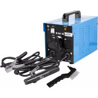
figure 2
- Electrode cable (+)
- Ground cable (-)
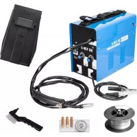
figure 3
Hose with adapter
that the following Appliance complies with the appropriate basic safety and health requirements of the EC Directive based on its design and type, as brought into circulation by us.
In a case of alternation of the machine, not agreed upon by us, this declaration will loose its validity.
Applicable EC Directives: - 2006/95/EC
Date/Authorized Signature:
that the following Appliance complies with the appropriate basic safety and health requirements of the EC Directive based on its design and type, as brought into circulation by us.
In a case of alternation of the machine, not agreed upon by us, this declaration will loose its validity.
Directives CE applicables: - 2004/108/EC
Applicable EC Directives: - 2006/95/EC
Normes harmonisées applicables: - EN 60974-1:2005
Applicable harmonized -EN 60974-10:2007
Standard:
Date/Authorized Signature:
Autorisé à signer:
Title of Signatory:

Documentation technique: J. Burkle; FBL, QS
CZ
that the following Appliance complies with the appropriate basic safety and health requirements of the EC Directive based on its design and type, as brought into circulation by us.
In a case of alternation of the machine, not agreed upon by us, this declaration will loose its validity.
Applicable EC Directives: - 2006/95/EC
Applicable harmonized
Standard
- EN 60974-1:2005
Datum/podpis vyrobce:
Date/Authorized Signature:
Udaje o podepsaném:
Title of Signatory:
that the following Appliance complies with the appropriate basic safety and health requirements of the EC Directive based on its design and type, as brought into circulation by us.
In a case of alternation of the machine, not agreed upon by us, this declaration will loose its validity.
Oznacenie pristrojov:
- 100 GC, 140 GC, 160 GC
Cisla vyrobkov: Article-No.:

Prisluşné smernice EU: - 2004/108/ EC
Applicable EC Directives: - 2006/95/EC
normy: Applicable harmonized Standard:
-EN 60974-10:2007
Datum/podpis vyrobcu:
Date/Authorized Signature:
Udaje o podpisanom:
Title of Signatory:
21.06.2011
pán Arnold, konate!
that the following Appliance complies with the appropriate basic safety and health requirements of the EC Directive based on its design and type, as brought into circulation by us.
In a case of alternation of the machine, not agreed upon by us, this declaration will loose its validity.
Applicable EC Directives: - 2006/95/EC
Date/Authorized Signature:
EC Declaration of Conformity
Con la presente, la ditta Gude GmbH & Co. KG We hereby declare, Birkichstraße 6, 74549 Wolpertshausen, Germany dichiara
that the following Appliance complies with the appropriate basic safety and health requirements of the EC Directive based on its design and type, as brought into circulation by us.
In a case of alternation of the machine, not agreed upon by us, this declaration will loose its validity.
Dirittive CEE relative: -2004/108/EC
Applicable EC directives: -2006/95/EC
Standard normativi in merito applicati: EN 60974-1:2005 Applicable harmonized -EN 60974-10:2007 Standard:
that the following Appliance complies with the appropriate basic safety and health requirements of the EC Directive based on its design and type, as brought into circulation by us.
In a case of alternation of the machine, not agreed upon by us, this declaration will loose its validity.
Applicable EC Directives: - 2006/95/EC
Applicable harmonized
Standard
- EN 60974-1:2005
-EN 60974-10:2007
Date/Authorized Signature:
EC Declaration of Conformity
Temeljem ove izjave, mi, Gude GmbH & Co. KG
We herewith declare, Birkichstraße 6, 74549 Wolpertshausen, Germany
proglašavamo da dole navedeni uredaji, u pogledu njihove koncepcije i konstrukcije kao i u pogledu izvedbi koje smo uveli u promet, ispunjavaju odgovarajuće osnovne zahtjeve u vezi sigurnosti i zdravlja prema smjernicama EU.
that the following Appliance complies with the appropriate basic safety and health requirements of the EC Directive based on its design and type, as brought into circulation by us.
In a case of alternation of the machine, not agreed upon by us, this declaration will loose its validity.
Oznaka uredaja: - 100 GC, 140 GC, 160 GC
Machine Description:
Nar.broj: -20055, 20046, 20047
Article-No.:
Applicable EC Directives:
2006/95/EC
Primijenjene harmonizirane
norme: -EN 60974-1:2005
Applicable harmonized - EN 60974-10:2007
Standards:
Date/Authorized Signature:
21.06.2011
Podaci o potpisanoj osobi gospodin Arnold, Direktor
Title of Signatory:
Tehnicakodumentacija:J.Burkle;FBL,QS
A.V. 2 Ponatis celega dokumenta ali njegovih delov je mozen po dogovoru s proizvajalcem. Tehnicne spremembe pridrzane. Prikazane slike prikazujejo primere.
that the following Appliance complies with the appropriate basic safety and health requirements of the EC Directive based on its design and type, as brought into circulation by us.
V primeru spremembe naprave, o kateri se niste posvetovali z nami, ta izjava izgubi svojo veljavnost.
In a case of alternation of the machine, not agreed upon by us, this declaration will loose ist validity.
Oznacitev naprav: -100 GC, 140 GC, 160 GC
Serijske st. izdelkov: -20055 Article-No.:
Ustrezne smernice EU: -2004/108/EC Applicable EC Directives: -2006/95/EC
Applicable harmonized Standard
-
EN 60974-10:2007
-
EN 60974-1:2005
Datum/podpis proizvajalca:
Date/Authorized Signature: Podatki o podpisniku:
Title of Signatory:
21.06.2011

gospod Arnold, direktor
HnKora He npaBeTe n3MeHeHna Ho TKOpneKbCbaa 3a 6e3oNaChocT, He r DaBaIte Ha KbcO N OcHpyeTe 3axpaHbAHeTo C TOK da 6bJe o60pyBaHO C dEiCTBaU 3a3emBaU qenCeI.
OcnypTe Do6po 3aMacraBaHe Ha pa6oThaTa Maca 3a 3abapBaHe.
KaKBaTO n da 6nIO noIdpBxka MoKe Da n3BbPbBa cAmo KBaINHPhiUpaH npcoHaN. Ocb3HaTe roEmna Pnck npou3Tuau, ot onaCHOTo eJIeKTPuuecko HappeKeHne, Koeto B3HKnBa pnpa60Ta c To3n ypeD.
Kapdnocthmynatopn

JIuca, KOINTO HOCAT eNEKTOPOHeH ypeI cnykaa 3a noDbpxKaHe Ha JKBOTa (HaNP. KAPdIOCTMMyIaTOp n.T.H.), 6n TpRbBLoJa da Ce nocBETBaT cNekap, npEdu Da ce MAnoXaT Ha BnAHHeTo Ha 3abapOBbUHN ypeDu 3a eNEKTOpIbROBO 3abapBAHe, pexeun nn ypeDu 3a n3rapHe nn ycTroNtBA 3a TOchKOBo 3abapBAHe 3a da 6bDat CNyprH, Ye MaRHTHOTOn ONE 3ae DHO C BnCOKInTe CTOnHOCTNa ENEKTPnueckn ToK Hma Da BnJraT Ha DeHocTTa HA TexHmIA ypeI.
Onncnne n cneunphkaaHa npodykta
yBOD
3axpaHbAHnraHa 3aBapbYnnaTOK OT nopeiua 80 A doCTaBt KOHCTaHTeH TOK i Ca KOHCTpynpaH c INHBEPTOPA H texhka, o6opyBaHn C MoUHN MHOrHaJeXdHn eMeHeTN I MOKe Da ce N3NoN3BaT 3a npbTOBn eNeKTPODn I 3a 3aBapRaHe c BoJppaMOB eNEKToD B 3aUnTHa aTMoccepa (OCBeH GA 100 KA # 20054, OCBeH GA 100 # 20045).
OnncHHe Ha cncTeMaTa
3axpaHbAHeTo Ha ToKa 3aeDnO c ynpabJBaAaTa IOnkA ca MOHTnPaHn Ha eDIneH rnaBeH nHaEn BbΦopMaTa Ha OTdEHN HxbpHnPiATKn, KOTMO MOrat B3aAMnHO da Ce 3ameHr. C TOBA cnCTeMaTApnpdoBnBA BVcOKa CTeENe HA HApExdHocT IN NOdpXKA t a cepBn3a ce yneChBaT. 3axpaHbAunia (CINOBn) Moyn cbDbPka IVHBETOP, KOITo pa6OtN CyeCTota No-BcOKa OT 80 kNt u MHORo KbCo BpeMe Ha peOahnc (500 MNiNeCKyUn). Pezytata o T oBa eMoro paBHomepHa 3aBapka c necho CTaptnaHe, XOMOREHHa RoIemnHa Ha KaKNTe N no-do6p npOHnKBaHe.
IorcheHne Ha TexHnueckKte 3HaUN
EN 60974 HOpMn
S/N/ CepneH Hmep - MoJ, NocOyTe, B cnyaH Ha KaKbTo n da 6nno 3aannTBAHn
MMA noXoJIO 3a 3aBapBaHe c o6Ma3aHn eKeTpoDn (eKeKToDn C nOKpNTne)
WIG IOxOa 3a 3aBapBaHe C BOnΦpAmOB eNeKToPD B 3aUnTeHa aTMocCepa
U. cekyHapHo 3anaIbauo HnpeKeHne
X Bpeme Ha BkHIOUVAhe - npOeHTeKypc.
BpeMeTo Ha BkIIOUBAHe nocOVA npoUeHTen Kypc OT 10 MNHyTN, B KOITOn 3axpaHbAHeTo Ha TOKa npn daDeHa CTOHOC HA TOKA pa60Tu 6e3 pnerpaBaHe
I TOK Ha 3aBapBaHe
U CekyHapHO HanpeXeHne cbc 3aBapbTuH TOK 12
U1 HOMnHaJIHo HAppeKeHne Ha MpeKaTa
1~50/60Hz MoHofpa3Ho 3axpaHbAe 50 mN 60 Hz
11 A6copbpan TOK npn cbOTBeTeH 3aBapbueH ToK 12. Pn 3axpaHbaHe C ToK 3a3abapBaHe C BONpamOB eJekTPOB B 3auHTeHa atmocpepa pa3deneTe cToHocTTa I C uCnOto 1,6.
IP21 KnaHa 3aunTa Ha MeTaNHaTa pama
S 10doxoadjo3a pa6oTa BbB BnCOKOp nckOBn o6naTn
Upea ydoBneTbopBa n3nckBaHnTa ha EN 60974-10,Knac A. Toba 03nauaba, ye ynoTppe6ata e pa3peeHa cAmo B npomuJneHa 3OHa. Ypea npn He6naorponpAHTn Cnyaan Moke da npedn3BnKa eJeKTPOMaTHN CmyeHn.
TOnnHHa 3aunTa
3aunTa npn nperepaBHe n nobpeHn 3axpaHbAHeTo c rnaBeH TOK
Bpe3yntat Ha Hameca Ha KOHTpOHNITE yCTPOINCTBa 3a MpeXoBO HAnPExeHne N B pe3yNTAT Ha nperpaBaHe (TOnnHHEN BKIOUBAteN Ha OXNaJDaIuTE TeJa) Ce N3KIOUvBa 3axpaHbAHeTO C TOK.
HcTannpahe
Pa3onakobaHe mHcTannpaHe
Pazonakobai Te ypeia n ro nprrnneaTe BHIMATEHIO, daan npri TpaHcnopTnpaHTo He ce c tTrHaNo do yBpejdaHe. EBeHTyann HcKahna 3a 3aIaaane Ha ueta pndnBHKn npri TpaHcnopTnpaHep Ta6Ba da ce npaxHBaT cnpmo npeo3bA. 3a da He 3arybnte npaba 3a 3aIauane Ha uetnte, 6n Tpa6BaNo HmIo da He noDnCBAte BnAnko, no ckopo da donuWe te 3abeJekka, ue cn 3anaBte npabTO da ynpaxHnTe NcKaHe 3a o6e3uTeHne B cnuyai, ye cned pazonakobae YctaHOBt e 9eTn npunHeHn np TpaHcnopTpapaHeTo.
Bcunckcb06eHnna 3a To3n ype n Tp8bda cblbpkaT moen n cepneH Hmep, KOHTO Ue HamepuTe Ha 3aHaTa cTpaHa Ha 3axpaHbAHeTo C TOK.
Cne pa3onakOBaHe IHCTaIIpaIte ypeHa Hdo6pe BENTINIPAHO, NO Bb3MOXHOCT Ha MRCTO 6e3 npax. EHNOBpeMeHHO BHIMBaIte Da He ce CTnHrNo do 6nOKpAHe Na pntoka Ha B3dyx Do oxnaJdaUte npope3n.
PpeynpeKdHHe: MHO e BaxHo Da He Ce CTnHe Do ORpaHuaBaHe Ha PnTOKa HA Bb3dyX OKoNo ypeDa, NoHEKe TOBa MoKe da DOBeDe Do HerOBOTnpERpaHa H peyIaT Ha ToBa Do nobPeHa Ha HkON BbTpewH CbCTABH Nactn.
OkoIyepaBnTpaBnDnMaMmHmym200MMcB6oJHO macto.He nocTaBnTe fnntpnKanaunnpaunTe OTbOpHa3xpaHbAHeto,BipotnbEN Cnyayi ry6nte rapahuOHnTe npaba.
3a6eIexka: Ako Hocnte ypeda Ha pamo, Tpra6Ba Da BHNIMabaTe Da He 6IoKnape BeHTNlaUOHHte OTBOpN.
HnTaJnpaHe
UpeDa Tp6Ba Da 6bDe MOHTnpaH OT ONTHn pa60THN. BcynK CbeINHeHr Tpr6Ba Da yOBDIeTBOPBbAT BaINHnTe npabnna u Tpr6Ba HnblHo Da cBoTBeCTBat Ha Hape6bnte 3a 6e3onacHocT (CENELEC HD 427).
06x3a6eEckn
Ipeynynotpe6aHaTOBa3axpaHbAneHaTOKaIpooyTeBHNMaTeJHO HopMITE CENELEC HD 407nHD 433.N3oJaIOHOHTe Ka6einn,3akONyAnKInTe 3a npDlbPkaHe H eNEKToPOnTe,ueCenTe n UeNcENHtE Kyttn Tpr6Ba da ce KOHTpOINpat n da ce Ocnpy DblnnHInTe nCeHHnraHa 3abapbUnHte Ka6einn da OTROBAPr Ha n36pannaTOK:
ДьннHa Ha Ka6eNa Do 5 M : МИнмално cehenne 16 MM²
Дьлжина Ha Ka6eJa 5-20 M : МИнмално ceунne 25 MM²
Дьнина Ha Ka6e9a 20 -30 M :MHIMaHcceHHe 35 MM²
Tyskahe B deiCTBne
Onncnne Ha KOMaHdHOTo Ta6No
Ha komaHnHOTo Ta6No ca pa3noJoxHeN:
- Konque 3a perynipane Ha ToKa
- KaebHHcbeHHeHHa eNEKTPoJa n 3aMaacBaUaTa KNeMa
- LED-ДиолзаИндикадиунlaЗавapчнгТOK(OKKoratoeBKNIOueH)
-
Xbnta lamna LED B HopmaHObcToHne e n3KIOueHa. PnC CBETBaHe MoKe Da CnHnHn3npa Te3N NOBpeH:
-
HanpexeHneTo Ha MPexKaTa ce pa3nUaBa noBce oT ± 10%.
- Ypea3a 3aBapraBaHe e npTeoBapeH.
3aBapraBaHe c 6Ma3aHn eNeKtpoDn (eNeKtpoDn c nokpntne)
EneKtpoKeHa e noDxOra 3a BCnKn BnOBN eNeKToPOu, n 3a ceynno3oBn eekTpoN (AWS 6010). NsON3BaIte 3akOnyAnKn 3a DbpxHe Ha eneKToPOnte 6e3 CTbpAuaa 3adbpkaa 5oNTOBe, KOIO OTOBAPrH a CbueCTByBaunr cTAndapt 3a 6e3OnaCHOCT. OcHpyre TnaBnB BKIOUbaTe H 3aHATA CTpaHa da 6be NoCTABeH B No3nue , "pecn. rNaBnB 3axpaHbau Ka6en Da He 6bde MyuHAT B uenceNeha Ktura. BkIOUeTe ZabApbUnHte KaBen b CbOTBeTCTBne C texHnNoJpHT nCnped dahnHite Ha npOn3BOInTeHa eneKToPOu. ToKobata Bepira Ha 3abapBaHe 6n Tpr8BaNo da He CTnra yMnJneHO b npKnn HnppK KOHTAKC npePn3HnKa6en, eHNCTBeHo Ha 3abapBaHn deTaHn.
Ako HanpaBnTE yMnIeHc 3a3emBaHe c nOmoHa npeDna3HnKa6en KbM 3abapBaHn deTaun, cBeHNHeHMeTo Tp8Ba Da 6bde KONKOTc Ce Moze No Kbco. CeeHMeTO Ha npeDna3Hn Ka6en Tp8Ba MmHmym Da 6bJe Taka rOJIMo KaTO ceueHMeTO Ha o6paTHn4 3abapBcHn Ka6en. Dbata Ka6ena Tp8Ba Da 6bDat npCbeDnHEn HkM 3abapBaHn deTaun B cbIoTO MRCTo. N3non3BaHTe 3amacBaUaTc KEma Ha yPeDa nn 3amacBaUa KEma B 6bn30ct.
He6xOIMO e da ce HnpaBRT BCnK INpeBaHTNBn MEpkn 3a da ce n36erHAT cKNTaun TOKOBE. PpOBepTe, daHn HAnpExeHneTo Ha MPexkata OTROBAPr HA BXoHOTo HANpExeHne Ha ypeDa.
BkIIOUbaHe Ha IJIaBHn 3axpaHbau Ka6e! Ppi MOnTaKaHa UeNceLa Tpr6Ba Da Ce BHIMaBA 3a NdoXoJaKanauTeT 3a TOBa, XbIto3eJEnHn npOBODnK Ha IJIaBHn Ka6e Da 6Be Cbbp3a Hc6 3a3emBaunu Zeencen.
Kanaunteta Ha TepMOMaHHTNBA KJIUOyBaTeI NIN Ha IpeDnA3NTeIITe Ha rnaBHaTa 3axpaHbAa Bepira 6n Tp8BaNo da 6bDe no- roJAM nIeHaKbB KaTo ToKa I1 a6copupan O ypeJa.
A6copbpanu TOK 11 ue onpeenite cne KaTO npOHTe TeXHuecknTe Cneunfkaun HA ypea Cnped rnaBHOto 3axpaHbaio Hapexehne U1. BcNy ydbJxntn Tp6Ba da ca cbc ceheHne, KoTo Da OTROBAPra HA a6copbpanu ToK 11. 3axpaHbaHeTo Ha TOKa ige BkIOHNTe c nOMoHa Ha IbnHBA BkIOHbATEn Ha 3aHnata CTpHa Ha ypea.
PNEyPEXDEHNE:
YDAPNTEOT ENEKTPNUECKN TOK MOFAT DA BbDAT CMBPTHOCHN!
HE DOKOCBAITE PPOBODIMM YACTN!
HE DOKOCBAI TE I3XODHNTE 3ABAPbHu IN PNCbEINHEHNA, KORATO YPEDA E BKJIIOUCH!
HIKOFA HE IOKOCBAIte EINHOBPEMEHNO EJEKTPOXEHA INI EJIEKTPODA N3AMACRAUATA KJIEMA!
I36peTe ToKa B 3aBnCmOcT OT CeueHHeTo Ha eNEKTPoJa,No3uYraHa 3aBaApBaHe N 3aBapKaTa.CneJ 3aBapBaHe MmCneTe 3a TOBa, Da I3KNIOHTe rAaBHn BkIOHbAteN Ja I3BaDITe eNEKTPoJa ot PbKOXBaTKaTa.
3aBapBaHe c 60pyDbaHe/npHaIeKHOCTn WIG (3a 3aBapBaHe c BONpam B 3aunTHa aTMocpepa): 3aBka No Gude 41690
IpeDn 3anOuBaHe Ha pa6oTa Tp86Ba Da HMaTe Ha pa3noNoKeHne Cb0TBeTHra3.
| Fe | I | cTomaHa | I | ArCO2 |
| Al | I | anymnHn | I | Ar (c To3n ypeD He moKe |
| V2A | I | 6naRopoJa cTomaHa | II | ArO2 |
Bkluohete ypea cnopeid cneHTo oncanHe:
IpiueHHe Ta0Bn MapKyu C nOmoa Ha 3akOnHaJaKa KbMa Ra0BaTa apMaTypa Ha cBoTBeHaTa 6yTuJa Ka n a CbpxTe C o6opyDbAHeTo WIG.
MyuHeTe uencena Ha o6OpyDbaHeTo WIG B cBoTBeTHa76yKc ,DInse"Ha HnHBeTpOpa (OTpuateneH noHKc).
BnmaHne: np3aBapBaHe WIG (c BOnppaMOB eNeKToD B 3aunTHa aTMocpepa) 3amacBaunKa6eI npectabnaBnnoxnten Hnnoc n naKeTa WIG orpuataen nnloc.
Cera MyshHeTe 3aMaC8BaunKa6eB N CbOToBeThata 6yKca (noJoxnTeJeH noHoc).
BONpamobata Hrna Haoctpete nepneHnkyjnpHO kMb IuaIpaunu dNcK n MyuHHeTe B cTraunTe Kneu. Otnpe6n Tp8bano OT kepaunHaT a du CTbpy npn 5 MM Bonpamoba irna (Bxk KapT.4-7).
Cera OTBopete rataOBnBaHTnHa ropeIkaTa (npu6n. 1/ o6oPOT) n npEeKnOyTe ypeDa Ha WIG (aKo e haHnue)
3anaBaHe: Cera nocTaBeTe Kpa Ha KepaMnHaTa IIO3a KOCO KbMaTePnaJa N eHOBpeMeHHo DnKKeTe CnTnTa Do MATEpna,doKaTo Bb3HnKe eNkTpuCeKa Ta.

UnpaXHeHnTo npabu MaNCTopa!
Kapt. 2 Kapt. 3
Ta3OB Mapkyc a danTOp
Дeкnapацnia 3a сходстBO c EC EC Declaration of Conformity
C ToBa DeKlApnpame Hne, Gude GmbH & Co. KG
We herewith declare, Birkichstraße 6, 74549 Wolpertshausen, Germany
Ye KOHcIeIa I KOHcTpyKUraHa dOynocOeHnTe ypeiB n3nBnHeHna, KOnTO nyCKaMe B 06pbJueHne, OTROBaPrt Ha cBoTBHTNe OCHOBn N3NCKBaHna HnHcTpyKuHnTe Ha EC 3a 6e3oNaChOCTn XnRHeHa.
that the following Appliance complies with the appropriate basic safety and health requirements of the EC Directive based on its design and type, as brought into circulation by us.
B cnuyaHa n3MeHHe Ha ypea, KoTo He e 6nNo KOhcyTnpaHo C Hac, Ta3N deKnapaunry6n CBoTa BaINHDocT.
In a case of alternation of the machine, not agreed upon by us, this declaration will loose its validity.
06o3NaueHne Ha ypeDnTe: -100 GC, 140 GC, 160 GC
Homepa Ha npodykTnTe: -20055
Article-No.:
CboTBeTHn Hape6n Ha EC: -2004/108/EC
Applicable EC Directives: - 2006/95/EC
U3noJ3BaHxapMOHn3IpaHn
HopMn: -EN 60974-1:2005
Applicable harmonized -EN 60974-10:2007
Standard
Data/NoOpnC Ha npOn3BoUTeJIa:
21.06.2011
Date/Authorized Signature:
Данн 3a NOДиСаня:
Title of Signatory:
rocn ApnoIa,ynpaBnteI
TexHHuecka DOKymeHTaIya:
J. Burkle; FBL, QS


!!! Prije prvog stavljanja uredaja u pigeon neophodno je pročitati sve informacije i uputstva navedene u ovom Prirucniku za korištenje.
We herewith declare,
Birkichstraße 6, 74549 Wolpertshausen, Germany
proglasavamo, da dole navedeni uredaji, u pogledu njihove koncepcie i konstrukcije kao i u pogledu izvedbi koje smo uveli u promet, ispunjavaju odgovarajuce osnovne directivesive bezbjednosti i zdravlja prema smjernicama EU.
that the following Appliance complies with the appropriate basic safety and health requirements of the EC Directive based on its design and type, as brought into circulation by us.
Ako dode do promjena na ureduju bez naše suglasnosti, ova Izjava postaje nevažćom.
In a case of alternation of the machine, not agreed upon by us, this declaration will loose its validity.
Oznaka uredaja: -100 GC, 140 GC, 160 GC
Serijski brojevi proizvoda: -20055 Article-No.:
20046 2
Primjenjive smjernice EU: -2004/108/EC Applicable EC Directives: -2006/95/EC
Primijenjene harmonizirane
norme: EN 60974-1:2005
Applicable harmonized - EN 60974-10:2007
Standard
Datum/Potpis proizvodača:
Date/Authorized Signaure:
Podaci o potpisanoj osobi
Title of Sinatory:
21.06.2011
gospodin Arnold, Direktor

Tehnicka dokumentacija: J. Burkle FBL; QS
that the following Appliance complies with the appropriate basic safety and health requirements of the EC Directive based on its design and type, as brought into circulation by us.
In a case of alternation of the machine, not agreed upon by us, this declaration will loose its validity.
Cihaz tanimi: -100 GC, 140 GC, 160 GC
Urun no.: -20055 Article-No.:
Applicable EC Directives: - 2006/95/EC
Kullanilan uyum
normlari: -EN 60974-10:2005
Applicable harmonized -EN 60974-1:2007
Standard
Date/Authorized Signature:
- A.V. 2 Surplus print even in shortened version requires permission.
- Warranty
- Device
- figure 1/8
- Technical Data
- General Safety Measures
- Protect the device against moisture, rain and dust.
- TO PROVIDE FOR MAXIMUM SAFETY, FOLLOW CAREFULLY THE INSTRUCTIONS BELOW:
- Location Requirements
- Emission Reduction
- Special Safety Regulations
- Introduction
- General Precautions
- Protection against Burns
- Fire Protection
- Toxic Combustion Gases
- Radiation
- Electrical Shock
- Pacemakers
- Product Description and Specification
- System Description
- Technical Symbols Glossary
- Thermal Protection
- Overheat Protection and Protection against Principal Current Supply Fault
- Installation
- Unpacking and Installation
- General Notes
- Start up
- Control Panel Description
- Sheathed Electrode Welding
- WARNING: ELECTRIC SHOCKS MAY BE FATAL!
- figure 2
- figure 3
- EC Declaration of Conformity
- Kapdnocthmynatopn
- Onncnne n cneunphkaaHa npodykta
- yBOD
- OnncHHe Ha cncTeMaTa
- IorcheHne Ha TexHnueckKte 3HaUN
- TOnnHHa 3aunTa
- 3aunTa npn nperepaBHe n nobpeHn 3axpaHbAHeTo c rnaBeH TOK
- HcTannpahe
- Pa3onakobaHe mHcTannpaHe
- HnTaJnpaHe
- 06x3a6eEckn
- Tyskahe B deiCTBne
- Onncnne Ha KOMaHdHOTo Ta6No
- 3aBapraBaHe c 6Ma3aHn eNeKtpoDn (eNeKtpoDn c nokpntne)
- PNEyPEXDEHNE:
- Bkluohete ypea cnopeid cneHTo oncanHe:
- BnmaHne: np3aBapBaHe WIG (c BOnppaMOB eNeKToD B 3aunTHa aTMocpepa) 3amacBaunKa6eI npectabnaBnnoxnten Hnnoc n naKeTa WIG orpuataen nnloc.
- Kapt. 2 Kapt. 3
- Дeкnapацnia 3a сходстBO c EC EC Declaration of Conformity
Brand : Güde
Model : 100 GC
Category : Welding machine