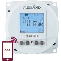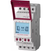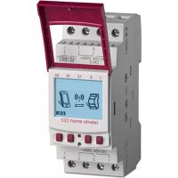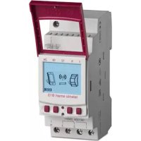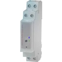
talento smart B10 mini - Switch Grässlin - Free user manual and instructions
Find the device manual for free talento smart B10 mini Grässlin in PDF.



| Product type | Switch (Modular timer) |
| Brand | Grässlin |
| Model | talento smart B10 mini |
| Supply voltage | 110-230 V~ |
| Number of channels | 1 |
| Radio frequency | 2.4 GHz |
| Max transmission power | 1.8 mW |
| Mode of operation | 1.B (EN 60730-1) |
| Pollution degree | 2 |
| Rated impulse withstand voltage | 4000 V |
| Mounting | DIN rail (EN 60715) |
| Display | 2 LEDs (white, green, yellow, blue, red) |
| Control functions | ON, OFF, OVR, Auto, Fixed, Reset, Bootloader |
| Controls | Control button, reset button |
| Programming | Via mobile app (Android/iOS) or PC software |
| Protection | IP20 (estimation) |
| Material | Plastic |
| Weight | ~100 g |
| Certifications | FCC (ID: 2AHH7-B10), CE |
| Languages of manual | FR, CS, DA, DE, EN, ES, FI, HU, IT, NL, PL, PT, SV |
| Additional features | Firmware update, PIN lock |
Frequently Asked Questions - talento smart B10 mini Grässlin
User questions about talento smart B10 mini Grässlin
0 question about this device. Answer the ones you know or ask your own.
Ask a new question about this device
Download the instructions for your Switch in PDF format for free! Find your manual talento smart B10 mini - Grässlin and take your electronic device back in hand. On this page are published all the documents necessary for the use of your device. talento smart B10 mini by Grässlin.
USER MANUAL talento smart B10 mini Grässlin
natural_image
Technical line drawing of an electrical component with three terminals and a central door (no text or symbols)GRÄSSLIN
DE Bedienungsanleitung 2
EN Operating manual 14
FR Notice d'utilisation 26
IT Manuale operativo 38
ES Instrucciones de 50
manejo
PT Instruções de uso 62
NL Bedieningshand-leiding 74
cs Návod k obsluze 86
sv Användningsinstruk-
tion 98
NO Betjeningsanvisning 110
DA Betjeningsvejledning 122
FI Käyttöopas 134
PL Instrukcja obsługi 146
HU Kezelési utasítás 158
Registration numbers 170
talento smart
B10 mini

text_image
Technical diagram of an electrical contactor with numbered parts labeled 1 through 9text_image
Diagram of a device rear panel with labeled components including buttons, connectors, and portsnatural_image
Diagram showing a mechanical or architectural component with an arrow indicating motion, labeled 'A' at the bottom (no text or symbols on the diagram itself)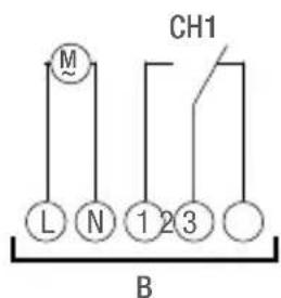
text_image
M CH1 L N 1 2 3 BThis manual ensures safe and efficient use of the DIN-rail timer (referred to as “device” in the following). This manual is a component of the device and must remain accessible at all times for everyone who uses the device. Everyone who uses the device must have read and understood this manual before commencing any work. The basic prerequisite for working safely is compliance with all safety instructions and usage instructions specified in this manual.
Copyright
This manual is copyright protected.
Handover of this manual to third parties, reproductions of any type and form – including excerpts – and use and/or disclosure of the content without the written permission of the manufacturer, except for internal purposes, is not permitted. Violations will result in liability for compensation. The manufacturer reserves the right to assert additional claims.
The copyright is held by the manufacturer.
Download
You can find the following information at www.graesslin.de:
Download instructions and technical data.
Declaration of conformity
Grässlin GmbH hereby declares that the radio system type “talento smart B10 mini” conforms to Directive 2014/53/EU. The complete text of the EU declaration of conformity is available from the following Internet address: http://qrc.graesslin.de/talento-smart-conformity.
EN

Overview....16

Safety 22

Installation 24

Disposal 25

Overview
text_image
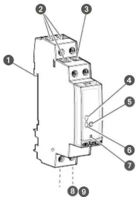
Technical diagram of an electrical contactor with numbered components for identificationFig. 1: DIN-rail timer
1 Click system for installation on a DIN rail
2 Terminals for channel 1
3 Potential-free empty terminal
4 LED 1
5 Control button
6 LED 2
7 Reset button
8 Terminal for neutral conductor
9 Terminal for phase

Description of function
The DIN-rail timer is a timer that is installed on a DIN rail (Fig. 1/①) by means of a click system; the timer activates the connected device. The DIN-rail timer has one channel and can be operated via a control button (Fig. 1/⑤). The state of the DIN-rail timer is indicated by two LEDs (Fig. 1/④ and ⑥). The DIN-rail timer can be programmed using an app on a mobile device or using PC software. The radio signal frequency is 2.4 GHz and the maximum transmission power is 1.8 mW.
Technical data (DIN EN 60730-1)
Mode of operation 1.B
Pollution degree 2
Rated impulse voltage 4000 V
The technical data for the devices described in this manual can be found at:
http://qrc.graesslin.de/talento-smart-specs.

Display and control elements
text_image
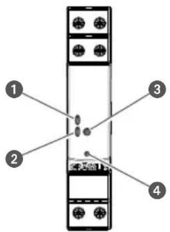
Diagram of a device rear panel with labeled components including buttons, connectors, and portsFig. 2: Display and control elements
1 LED 1
2 LED 2
3 Control button
4 Reset button

Function of buttons (Fig. 2 ③ and ④)
ON (FIX) Permanently switch on the channel.
OFF (FIX) Permanently switch off the channel.
OVR The current programme is overwritten up to the next automatic command.
Reset Start a reset.
Activate boot loader
Boot loader mode must be activated before an update:
- Press the reset button.
- At the same time, press and hold the control button for two seconds.
- Release the reset button.
- Release the control button.
- LED 1 flashes blue twice

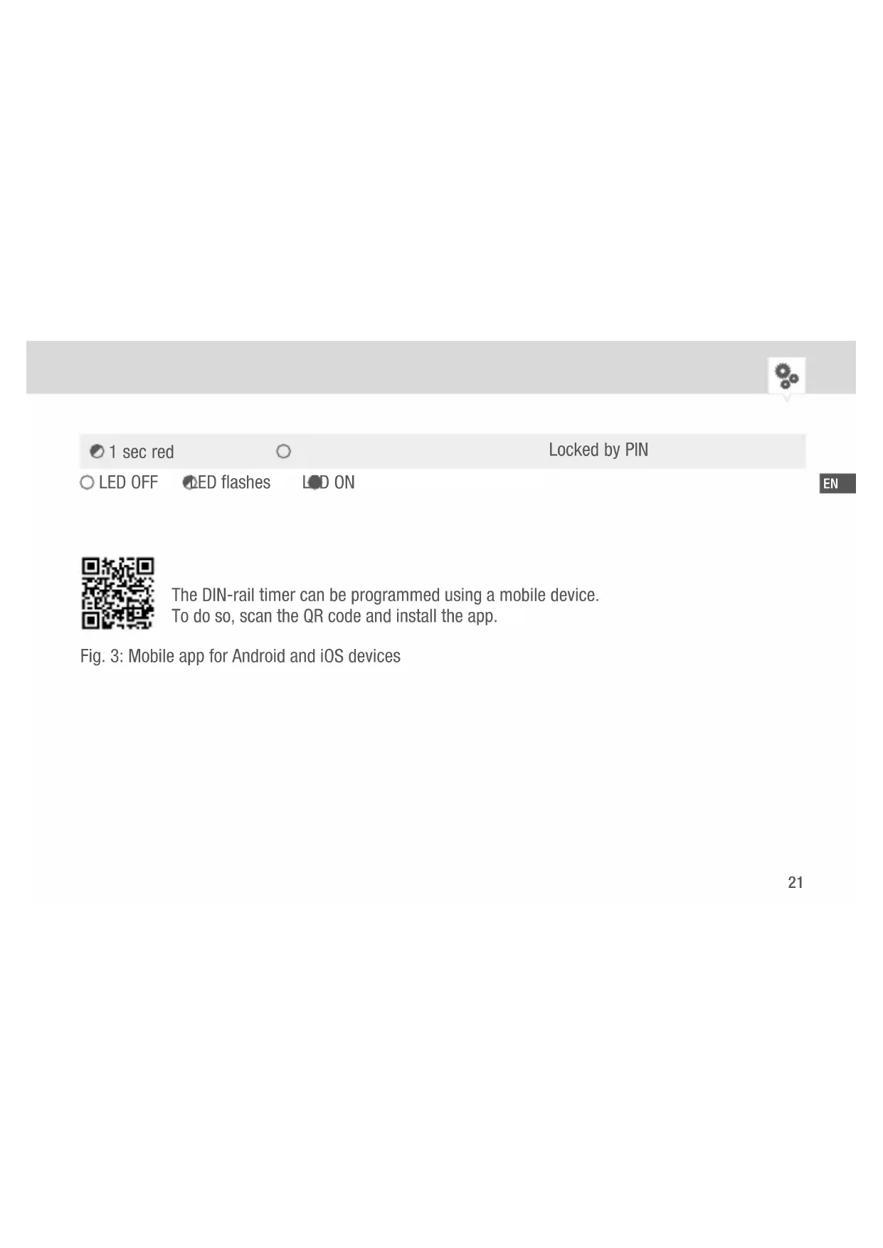
| LED 1 (Fig. 2 1) LED 2 (Fig. 2 2) | Description | |
| ○ | ● white | Relay OFF |
| ○ | ● green | Relay ON |
| ○ | ○ | Power OFF |
| ○ | ● white / ● green (relay status) | Auto mode |
| ○ yellow white / green (relay status) | OVR mode | |
| ● yellow white / green (relay status) | FIX mode | |
| ● blue white / green (relay status) | Bluetooth connected | |
| ○ 2 × blue | ○ | Boot loader active |
| ○ blue | ○ | Firmware update |
| ○ red red | ○ | No time |
| ○ 3 × white 3 × white | ○ | Factory reset |


1 sec red

Locked by PIN

LED OFF

ED flashes

ON

The DIN-rail timer can be programmed using a mobile device. To do so, scan the QR code and install the app.
Fig. 3: Mobile app for Android and iOS devices

Safety
Intended use
- The DIN-rail timer is intended solely for switching electric devices in private and commercial areas, provided this does not infringe on the intended use of these devices.
- The DIN-rail timer may only be installed on DIN rails.
- Only use the DIN-rail timer in dry rooms and do not install close to devices with inductive discharge (motors, transformers, etc.).
The intended use also includes compliance with all information specified in this manual. Any use other than the intended use is considered incorrect use. The legal warranty is voided by any interference with, or modifications to, the device.

Residual risk
WARNING!
Risk of fatal electric shock!
Improper assembly and installation of the device can lead to life-threatening electrical voltages.
- Only allow a qualified electrician to install and connect the device.
FCC Certification
FCC ID: 2AHH7-B10
This device complies with Section 15 of the FCC Regulations. Operation is only permitted under the following conditions: (1) This device must not cause any disruptive interferences and (2) the device must be able to receive interferences, also such interferences which could result in undesired operations.
IT
Installation
natural_image
Simple diagram showing a mechanical or architectural component with an arrow indicating motion, labeled 'A' at the bottom (no text or symbols on the diagram itself)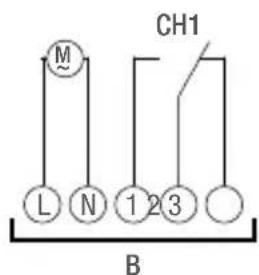
text_image
M CH1 L N 1 2 3 BFig. 4: Installation on a DIN rail and circuit diagram
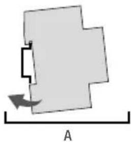
A Installation on a DIN rail
B 110-230 V 1-channel DIN-rail timer
- Place the DIN-rail timer on the DIN rail (Fig. 4/A) from above and press it back until it locks into place.
- Install the DIN-rail timer in accordance with the circuit diagram (Fig. 4/B) (use wires with a cross-section between 1 ~mm^2 and 2.5 ~mm^2 ).
Disposal
Improper disposal
ENVIRONMENTAL PROTECTION!
Incorrect disposal presents an environmental danger.
Incorrect disposal could result in environmental dangers.
Electric scrap and electronic components must be disposed of correctly, i.e. the parts for disposal must be sorted into material groups.
- Disposal must be environmentally responsible and must employ state-of-the-art environmental protection, recycling and disposal technology.


text_image
Technical diagram of an electrical contactor with numbered components for identificationFig. 1: Horloge modulaire
text_image
Diagram of a device rear panel with labeled components and internal componentsnatural_image
Simple diagram showing a mechanical or architectural component with an arrow indicating motion, labeled 'A' at the bottom (no text or symbols on the diagram itself)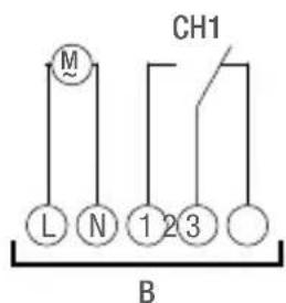
text_image
M CH1 L N 1 2 3 Btext_image
Technical diagram of an electrical contactor with numbered components for identificationtext_image
Diagram of a device rear panel with labeled components including buttons, connectors, and portsnatural_image
Diagram showing a mechanical or architectural component with an arrow indicating motion, labeled 'A' at the bottom (no text or symbols on the diagram itself)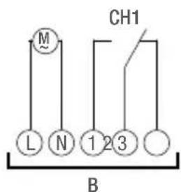
text_image
M CH1 L N 1 2 3 Btext_image
Technical diagram of an electrical contactor with numbered parts labeled 1 through 9Fig. 1: Interruptor horario de carril DIN
text_image
Diagram of a device rear panel with labeled components including buttons, connectors, and portsnatural_image
Diagram showing a mechanical or architectural component with an arrow indicating motion, labeled 'A' at the bottom (no text or symbols on the diagram itself)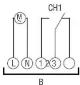
text_image
M CH1 L N 1 2 3 Btext_image
Technical diagram of an electrical contactor with numbered parts labeled 1 through 9text_image
Diagram of a device rear panel with labeled components including buttons, connectors, and portsnatural_image
Diagram showing a mechanical or architectural component with an arrow indicating motion, labeled 'A' at the bottom (no text or symbols on the diagram itself)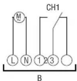
text_image
M CH1 L N 1 2 3 Btext_image
Technical diagram of an electrical contactor with numbered parts labeled 1 through 9text_image
Diagram of a device rear panel with labeled components including buttons, connectors, and ports1 LED 1
2 LED 2
3 Bedientoets
4 Reset-knop
Afb. 2: Weergave- en bedieningselementen

natural_image
Simple diagram showing a mechanical or architectural component with an arrow indicating motion, labeled 'A' at the bottom (no text or symbols on the diagram itself)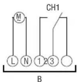
text_image
M CH1 L N 1 2 3 BAfb. 4: Montage op DIN-rail en schakelschema
text_image
Technical diagram of an electrical contactor with numbered components for identificationtext_image
Diagram of a device rear panel with labeled components including buttons, connectors, and portsnatural_image
Simple diagram showing a mechanical or architectural component with an arrow indicating motion, labeled 'A' at the bottom (no text or symbols on the diagram itself)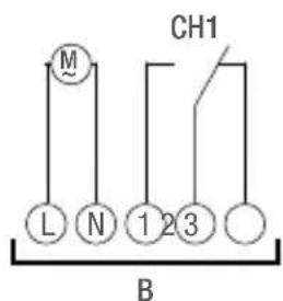
text_image
M CH1 L N 1 2 3 Btext_image
Technical diagram of an electrical contactor with numbered parts labeled 1 through 9Bild 1: Kopplingsur
text_image
Diagram of a device rear panel with labeled components including buttons, connectors, and portsnatural_image
Simple diagram showing a mechanical or architectural component with an arrow indicating motion, labeled 'A' at the bottom (no text or symbols on the diagram itself)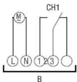
text_image
M CH1 L N 1 2 3 Btext_image
Technical diagram of an electrical contactor with numbered parts labeled 1 through 9Fig. 1: Fordelingstidsur
1 Klikksystem for montering på DIN-skinne
2 Tilkoblingsklemmer for kanal 1
3 Potensialfri tom klemme
4 LED 1
5 Betjeningstast
6 LED 2
⑦ Tilbakestillingsknapp
8 Tilkoblingsklemme for nøytralleder
9 Tilkoblingsklemme for fase

text_image
Diagram of a device rear panel with labeled components including buttons and indicators1 LED 1
2 LED 2
3 Betjeningstast
4 Tilbakestillingsknapp
Fig. 2: Visnings- og betjeningselementer

natural_image
Simple diagram showing a mechanical or architectural component with an arrow indicating motion, labeled 'A' at the bottom (no text or symbols on the diagram itself)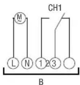
text_image
M CH1 L N 1 2 3 Btext_image
Technical diagram of an electrical contactor with numbered components for identificationFig. 1: Kontaktur
text_image
Diagram of a device rear panel with labeled components including buttons, connectors, and ports1 LED 1
2 LED 2
3 Betjeningsknap
4 Nulstillingsknap
Fig. 2: Visnings- og betjeningselementer

natural_image
Simple diagram showing a mechanical or architectural component with an arrow indicating motion, labeled 'A' at the bottom (no text or symbols on the diagram itself)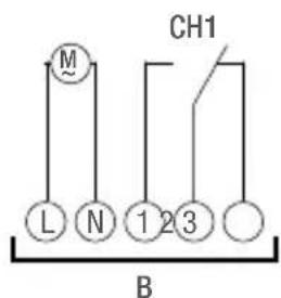
text_image
M CH1 L N 1 2 3 Btext_image
Technical diagram of an electrical contactor with numbered components for identificationtext_image
Diagram of a device rear panel with labeled components including buttons, connectors, and ports1 LED 1
2 LED 2
3 Painike
4 Reset-painike

natural_image
Diagram showing a mechanical or architectural component with an arrow indicating motion, labeled 'A' at the bottom (no text or symbols on the diagram itself)
text_image
M CH1 L N 1 2 3 Btext_image
Technical diagram of an electrical contactor with numbered components for identificationtext_image
Diagram of a device rear panel with labeled components including buttons, connectors, and portsnatural_image
Diagram showing a mechanical or architectural component with an arrow indicating motion, labeled 'A' at the bottom (no text or symbols on the diagram itself)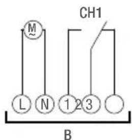
text_image
M CH1 L N 1 2 3 Btext_image
Technical diagram of an electrical contactor with numbered parts labeled 1 through 9text_image
Diagram of a device rear panel with labeled components including buttons, connectors, and portsnatural_image
Diagram showing a mechanical or architectural component with an arrow indicating motion, labeled 'A' at the bottom (no text or symbols on the diagram itself)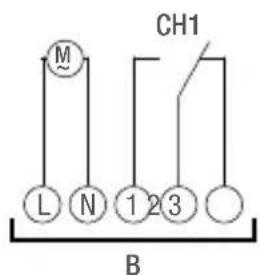
text_image
M CH1 L N 1 2 3 BRegistration numbers
USA
FCC-Zertifizierung
FCC ID: 2AHH7-B10
This device complies with Section 15 of the FCC Regulations. Operation is only permitted under the following conditions: (1) This device must not cause any disruptive interferences and (2) the device must be able to receive interferences, also such interferences which could result in undesired operations.
Canada
IC: 21619-B10
This device contains licence-exempt transmitter(s)/receiver(s) that comply with Innovation, Science and Economic Development Canada's licence-exempt RSS(s). Operation is subject to the following conditions:
- This device may not cause interference.
- This device must not accept any interference, including interference that may cause undesired operation of the device.