SUPW3M - Wall mount SONY - Free user manual and instructions
Find the device manual for free SUPW3M SONY in PDF.
| Product type | Wall mount for TV |
| Brand | Sony |
| Model | SUPW3M |
| Compatibility | Sony TVs KDE-W50A12U and KE-W50A10E |
| Maximum supported weight | 52 kg (114 lb 11 oz) |
| Adjustable tilt angle | 0, 5, 10, 15, 20 degrees |
| Plate dimensions (L × H × P) | 670 × 420 × 79 mm |
| Frame dimensions (L × H) | 520 × 85.5 mm |
| Wall screw spacing | 393 ± 0.5 mm (horizontal) |
| Built-in speaker | Yes, 10 cm element (2) |
| Speaker impedance | 4 Ω |
| Maximum speaker power | 50 W |
| Wall mounting type | 4 M8 screws (not supplied) minimum |
| Materials | Painted steel |
| Installation | By a certified installer only |
| Number of parts supplied | Frame (1), hooks (4), diagrams (3), screws (4 + 6) |
| Required tools | Phillips screwdriver |
| Operating temperature | Not specified |
Frequently Asked Questions - SUPW3M SONY
User questions about SUPW3M SONY
0 question about this device. Answer the ones you know or ask your own.
Ask a new question about this device
Download the instructions for your Wall mount in PDF format for free! Find your manual SUPW3M - SONY and take your electronic device back in hand. On this page are published all the documents necessary for the use of your device. SUPW3M by SONY.
USER MANUAL SUPW3M SONY
Thank you for purchasing this product.
To Customers
Sufficient expertise is required for installing this product. Be sure to subcontract the installation to Sony dealers or licensed contractors and pay special attention to safety during the installation. Sony is not liable for any damages or injury caused by mishandling or improper installation. Your Statutory Rights (if any) are not affected.
Disposal of this product
natural_image
Symbol of a trash bin crossed out by two diagonal lines (no text or numbers present)
Disposal of Old Electrical & Electronic Equipment (Applicable in the European Union and other European countries with separate collection systems)
This symbol on the product or on its packaging indicates that this product shall not be treated as household waste. Instead it shall be handed over to the applicable collection point for the recycling of electrical and electronic equipment. By ensuring this product is disposed of correctly, you will help prevent potential negative consequences for the environment and human health, which could otherwise be caused by inappropriate waste handling of this product. The recycling of materials will help to conserve natural resources. For more detailed information about recycling of this product, please contact your local Civic Office, your household waste disposal service or the shop where you purchased the product.
WARNING
If the safety precautions are not observed or the product is used incorrectly, it may result in serious injury or fire.
This instruction manual shows the correct handling of the product and important precautions necessary to prevent accidents. Be sure to read this manual thoroughly and use the product correctly. Keep this manual available for future reference.
To Sony dealers
Sufficient expertise is required for installing this product. Be sure to read this instruction manual thoroughly to do the installation work safely. Sony is not liable for any damages or injury caused by mishandling or improper installation. Please give this manual to the customer after installation.
On Safety
Products by Sony are designed with safety in mind. If the products are used incorrectly, however, it may result in a serious injury through fire, electric shock, the product toppling over, or the product dropping. Be sure to observe the precautions for safety to prevent such accidents.
CAUTION
Specified products (As of April 2005)
| Flat-Panel Colour Television | KDE-W50A12UKE-W50A10E |
This Wall-Mount Bracket is designed for use with the specified products above.
For other TVs, refer to their operating instructions to check if this Wall-Mount Bracket can be used.
Some TVs are supplied with a leaflet explaining how to install the Wall-Mount Bracket ("Installing the Wall-Mount Bracket").
To Customers
WARNING
If the following precautions are not observed, serious injury or death through fire, electric shock, the product toppling over, or the product dropping can result.
Be sure to subcontract the installation to licensed contractors and keep small children away during the installation.
If the Wall-Mount Bracket or the TV is not installed correctly, the following accidents may occur. Be sure licensed contractors carry out installation.
- The TV may fall and cause a serious injury such as a bruise or a fracture.
- If the wall on which the Wall-Mount Bracket is installed is unstable, uneven, or not perpendicular to the floor, the unit may fall and cause injury or property damage. The wall should be capable of supporting a weight of at least four times the TV weight. (See the TV installing dimensions table on page 16 for the weight of each TV.)
- If the installation of the Wall-Mount Bracket on the wall is not sufficiently sturdy, the unit may fall and cause injury or property damage.
natural_image
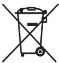
Cartoon illustration of a person running toward a large rectangular object with motion lines indicating impact (no text or symbols)Be sure to subcontract moving or dismounting of the TV to licensed contractors.
If persons other than licensed contractors transport or dismount the TV, it may fall and cause injury or property damage. Be sure that two or more persons carry or dismount the TV.
Do not spill liquid of any kind on the TV.
If you allow the TV to get wet, this may result in a fire or an electric shock.
Do not remove screws, etc., after mounting the TV.
If you do so, the TV may fall and cause injury or property damage.
Do not disassemble or make alterations to the parts of the Wall-Mount Bracket.
If you do so, the Wall-Mount Bracket may fall and cause injury or property damage.
natural_image
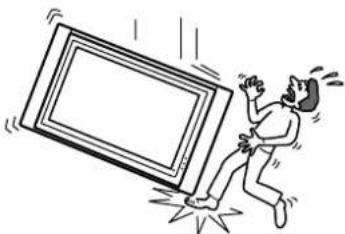
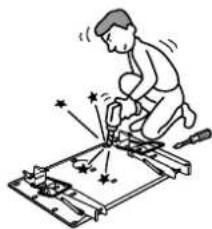
Illustration of a person using a tool to cut or mark a mechanical component with stars and arrows (no text or symbols)Do not mount any equipment other than the specified product.
This Wall-Mount Bracket is designed for use with the specified product only. If you mount equipment other than specified, it may fall or break, and cause injury or property damage.
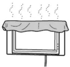
Do not cover the ventilation hole of the TV.
If you cover the ventilation hole (with a cloth, etc.), heat may build up inside and cause fire.
natural_image
Simple line drawing of a steaming container with lid and side panel (no text or symbols)Do not apply any load other than the TV on the Wall-Mount Bracket.
If you do so, the TV may fall and cause injury or property damage.
natural_image
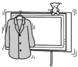
Illustration of a suit hanging on a monitor with a small bear figurine nearby (no text or symbols)Do not lean on or hang from the TV.
Do not lean on or hang from the TV as it may fall on you and cause serious injury.
Do not expose the TV to rain or moisture.
It may cause a fire or an electric shock.
Never place the TV in hot, humid or excessively dusty places, or in the place where the TV is subjected to mechanical vibrations.
If you do so, it may cause a fire or an electric shock.
Keep flammable objects or open flames (e.g. candles) away from the TV.
To prevent a fire, keep flammable objects or open flames (e.g. candles) away from the TV.
CAUTION
If the following precautions are not observed, injury or property damage may occur.
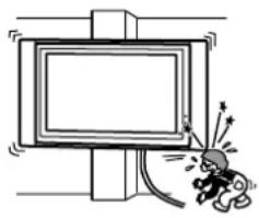
Do not install the Wall-Mount Bracket on wall surfaces where the corners or the sides of the TV protrude away from the wall surface.
Do not install the Wall-Mount Bracket on wall surfaces such as a pillar, where the corners or the sides of the TV protrude away from the wall surface. If a person or object happens to hit the protruded corner or side of the TV, it may cause injury or property damage.
natural_image
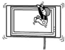
Cartoon illustration of a person reacting with a device to stand (no text or symbols)Do not handle the product with excessive force during cleaning or maintenance.
Do not apply excessive force on the topside of the TV. If you do so, the TV may fall and cause injury or property damage.
Do not install the TV over or under an air-conditioner.
If the TV is exposed to water leaks or air current from an air-conditioner for a long time, it may cause a fire, an electric shock or a malfunction of the TV.
Precautions
- If you use the TV installed on the Wall-Mount Bracket for a long time, the wall behind or above the TV may become discolored or the wallpaper may come unstuck, depending on the material of the wall.
- If the Wall-Mount Bracket is removed after installing it on the wall, the screw holes are left.
- If you have routed 300-ohm feeder cables behind the wall, we recommend that you change them to 75-ohm coaxial cables.
If it is necessary to continue to use 300-ohm feeder cables, be sure there is sufficient space available between the TV and the feeder cables behind the wall before installing. Consult your licensed contractor regarding an appropriate location (free from radio noise, etc.) before installing.
- Magnet influence
This TV contains a strong magnet in the speaker unit which generates magnetic influence. Keep any items that are susceptible to magnetic influence away from the TV speaker.
Installing the Wall-Mount Bracket
To Sony Dealers
WARNING
To Sony Dealers
The following instructions are for Sony Dealers only. Be sure to read safety precautions described above and pay special attention to safety during the installation, maintenance and checking of this product.
Be sure to install the Wall-Mount Bracket securely to the wall following the instructions in this instruction manual.
If any of the screws are loose or fall out, the Wall-Mount Bracket may fall and cause injury or property damage. Be sure to use the appropriate screws for the material of the wall and install the unit securely, using four or more M8 (or equivalent) screws.
natural_image
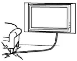
Technical line drawing of a mechanical assembly with no visible text or symbolsDo not allow the mains lead or the connecting cable to be pinched.
If the mains lead or the connecting cable is pinched between the unit and the wall or is bent or twisted by force, the internal conductors may become exposed and cause a short circuit or an electrical break. This may cause a fire or an electric shock.
natural_image
Simple line drawing of a hand holding a cable with a monitor on top (no text or symbols)Be sure to use the supplied screws and attachment parts properly following the instructions given in this instruction manual. If you use substitute items, the TV may fall, and cause bodily injury to someone or damage to the TV.
Be sure to assemble the bracket properly following the instructed procedure explained in this instruction manual.
If any of the screws are loose or fall out, the TV may fall, and cause bodily injury to someone or damage to the TV.
Be sure to tighten the screws securely in the designated position.
If you fail to do so, the TV may fall, and cause bodily injury to someone or damage to the TV.
Be careful not to subject the TV to shock during installation.
If the TV is exposed to shock, it may fall or break apart. This may cause injury.
Be sure to install the TV on a wall that is both perpendicular and flat.
If you fail to do so, the TV may fall and cause injury.
After proper installation of the TV, secure the cables properly.
If people or objects get tangled in the cables, this may result in injury or damage to the TV.
Be careful not to hurt your hands or fingers during the installation.
Be careful not to hurt your hands or fingers when installing the Wall-Mount Bracket or the TV.
The screws needed to secure the Wall-Mount Bracket to the wall are not supplied.
Use the appropriate screws for the wall material and structure when mounting the Wall-Mount Bracket.
Before installation
If your TV is supplied with a leaflet explaining how to install Wall-Mount Bracket ("Installing the Wall-Mount Bracket"), be sure to refer to the leaflet before installation.
Step 1: Checking the parts required for the installation
1 Prepare a Phillips screwdriver and the appropriate screws (four or more M8 (or equivalent) screws, not supplied), depending on the material of the wall, beforehand.
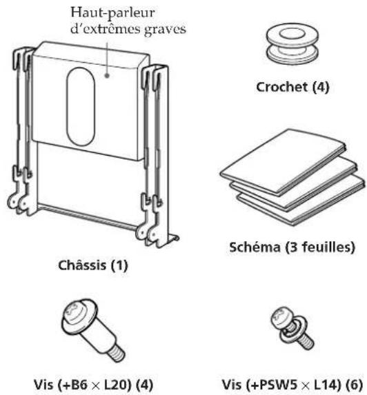
2 Open the package and check the parts.
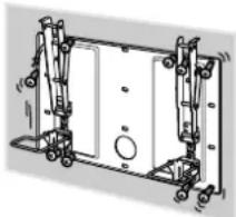
natural_image
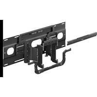
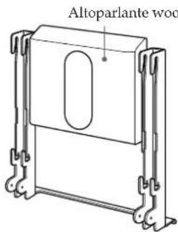
Technical line drawing of a mechanical assembly with mounting brackets and internal components (no text or symbols)Plate Unit (1)
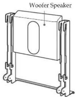
text_image
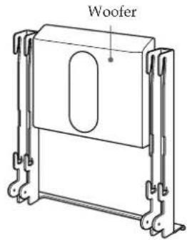
Woofer SpeakerMounting Rack (1)

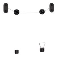
Hook (4)
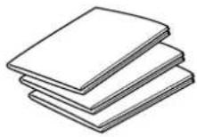
Paper Template
(1 set of 3 sheets)
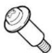
Screw (+B6 × L20) (4)

Screw (+PSW5 × L14) (6)
Step 2: Deciding on the installation location
1 Place the paper template on a perpendicular, flat wall and decide on the installation location.
Tape the supplied 3 sheets of the paper template together with commercially available adhesive tape. For details, refer to the instructions printed on the paper template.
Allow for suitable clearance between the TV and the ceiling and protruding parts of the wall as shown in the diagram below.
Note
If you intend to route the cables in a wall, make a hole in the wall beforehand to make sure that the cables can be drawn into the wall. The position for the cable hole is printed on the paper template and on page 17.
Unit: mm (inches)
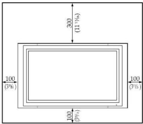
text_image
300 (11½) 100 (3½) 100 (3½)
natural_image
Two silhouettes of people assembling or adjusting a mechanical component (no text or symbols visible)2 Referring to the paper template and page 17, determine the positions of the screws. If you intend to route the cables in the wall, also determine the position of the cable hole and bore a hole in the wall.
WARNING
The wall that the TV will be installed on should be capable of supporting a weight of at least four times that of the TV (page 16).
Make sure of the strength of the wall the TV will be installed on. Reinforce the wall sufficiently, if necessary.
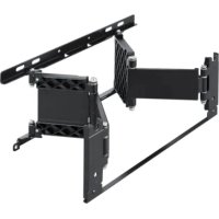
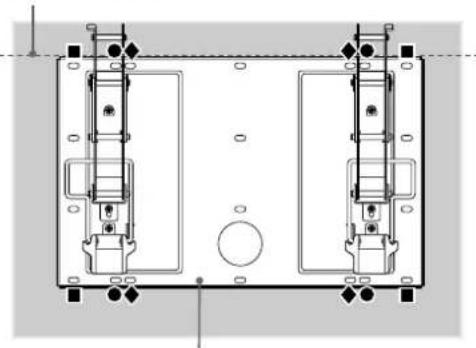
Step 3: Installing the Plate Unit on the wall
1 Fix the Plate Unit to the wall using four or more M8 (or equivalent) screws (not supplied).
Select at least four screw holes with the same mark shown in the diagram below, and tighten the screws securely so that they will not come loose.
WARNING
- The screws securing the Wall-Mount Bracket to the wall are not supplied.
- Be sure to use the appropriate screws, depending on the material and structure of the wall.
- If the Plate Unit cannot be attached securely enough, use additional screws.
- Be sure to confirm that the Plate Unit is securely fixed to the wall.
Align the unit so that it is exactly level.
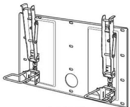
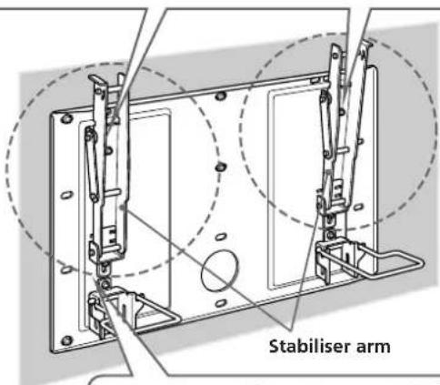
natural_image
Technical line drawing of a dual-chamber electrical enclosure or fixture assembly (no text or symbols)Plate Unit
2 Adjust the angle of the stabiliser arms.
When installing the TV perpendicularly (0 degrees), adjustment of the arms angle (step ① and ② below) is not necessary. Make sure that each stabiliser arm is screwed in securely.
① Remove the screws that are at the top and bottom center of the both stabiliser arms.
Then choose the notch corresponding to the desired angle (5, 10, 15 or 20 degrees) and fit the stabiliser arm to it.
② Firmly secure each stabiliser arm using the screws removed in step ①.
Notes
- Be sure to adjust the angles of the right and left arms to the same angle.
- Be careful not to pinch your fingers when adjusting the angle of arms.
-
When using an electric screwdriver, set the torque setting to approximately 2 N·m.
-
0 degrees: Leave the white screws tightened as they are.
- Other than 0 degrees: Remove the white screws.
text_image
Stabiliser arm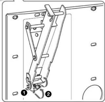
natural_image
Technical line drawing of a mechanical lifting device with two numbered components (1 and 2), no text or symbols present.Step 4: Preparing for the installation of the TV
1 Remove the screws that hold the TV to the Table-Top Stand.
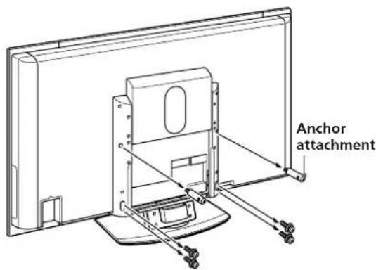
text_image
Anchor attachment2 Detach the TV from the Table-Top Stand, and place the TV, with its screen facing down, on a floor covered with a soft cloth.
natural_image
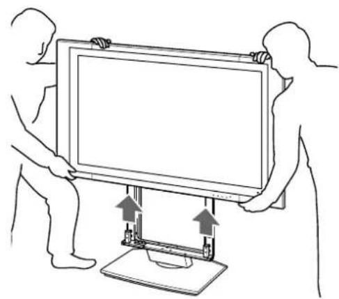
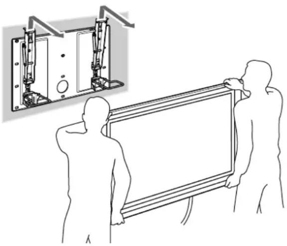
Line drawing of two people holding a large monitor with an upward arrow, mounted on a stand (no text or symbols)Note
Be sure that two or more persons hold the TV when carrying it. Do not hold the transparent parts at either the top or bottom of the TV.
3 Remove four screws on the rear side of the TV.
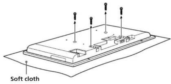
text_image
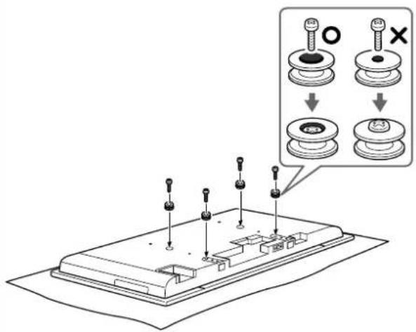
Soft cloth4 Attach the supplied four hooks with the four supplied screws (+PSW5 × L14).
text_image
Diagram showing a device with labeled components and an inset showing three circular components with 'O' and cross symbols.Notes
- When using an electric screwdriver, set the torque setting to approximately 2 N·m.
- Do not place the TV face down for an extended period as damage may occur to the front surface.
Step 5: Installing the TV
WARNING
Be sure to complete the installation before connecting the mains lead to the wall socket. If you allow the mains lead to be pinched under or between pieces of equipment, this may result in a short circuit or an electric shock. Be careful not to stumble over the mains lead or the TV, as you may hurt yourself.
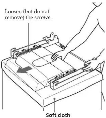
1 Change the position of the woofer speaker.
1 Loosen the four screws (two on each side of the strut arms) used to secure the woofer speaker in place about three turns.
② Slide the woofer speaker upward completely as shown below.
③ Retighten the four screws (loosened in step ①) to secure the woofer speaker.
text_image
Loosen (but do not remove) the screws. Soft clothNote
If you fail to slide the woofer speaker completely in step ②, the woofer speaker connector locating at the center bottom of the rear side of the TV and ventilation holes will be blocked resulting in product damage.
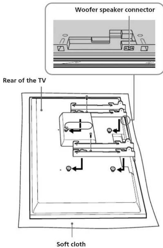
2 Hitch the Mounting Rack on the hooks on the rear side of the TV. Then slide the Mounting Rack and fix it using the supplied screws (+PSW5 × L14).
text_image
Woofer speaker connector Rear of the TV Soft clothNote
The woofer speaker connector is located on the lower right part of the Mounting Rack. When sliding the Mounting Rack, make sure that the woofer speaker is securely connected to the TV.
3 Connect the mains lead and the connecting cable(s) supplied with the TV to the TV.
Connect the mains lead and the connecting cable(s) to the connectors on the rear side of the TV. For details on connecting the mains lead and the connecting cable(s), refer to the instruction manual of the TV.
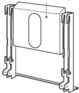
When you route the lead and the cable in the wall, feed them through the hole you bored (page 17).
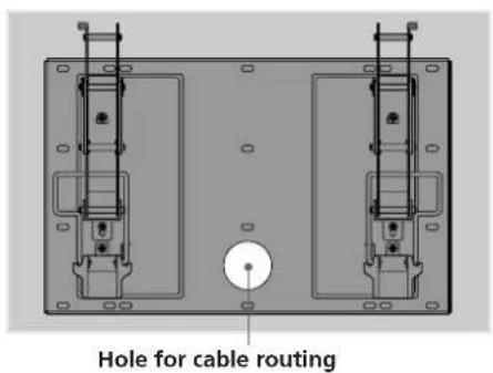
text_image
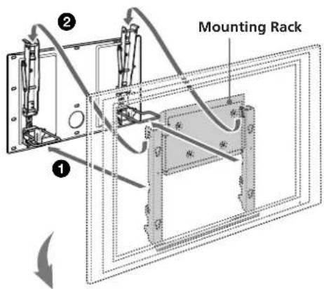
Hole for cable routing4 Install the Mounting Rack (with the TV) onto the Plate Unit.
1 Hold the Mounting Rack so that the two centre notches on either side touch the support braces of the Plate Unit.
② Gradually lift the Mounting Rack and TV upward keeping the centre notches engaged with the support braces of the Plate Unit. Hitch the upper left and right hooks of the Mounting Rack onto the anchor bars at the top of the left and right stabiliser arms of the Plate Unit.
3 Confirm the four upper hooks are firmly hooked onto the two anchor bars of the Plate Unit and that the support braces are secured in the centre notches of the Mounting Rack.
4 Firmly tighten all four upper and lower screws (+B6 × L20, supplied) on each side of the Mounting Rack.
text_image
Mounting Rack ① ②Side view
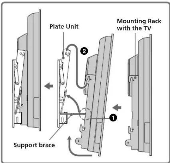
text_image
Support brace Plate Unit Mounting Rack with the TVRight side
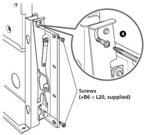
text_image
Screws (+B6 × L20, supplied)Confirming the completion of the installation
Check the following points.
- Four upper hooks of the Mounting Rack are firmly hooked onto the two anchor bars of the Plate Unit.
- The lead and the cable are not twisted or pinched.
- All the securing screws (+B6 × L20, supplied) are tightened.
WARNING
Incomplete installation may cause the product falling and result in injury or product damage. Also, improper placement of the mains lead, etc., may cause fire or electric shock through a short circuit.
Be sure to confirm the completion of the installation for safety.
Checking the operation of the woofer speaker
This Wall-Mount Bracket is equipped with a woofer speaker. After installing the Mounting Rack (with the TV) onto the Plate Unit, turn on the power switch of the TV and check if the woofer speaker is operating properly. If the TV is not installed on the Mounting Rack properly, no sound will be heard from the woofer speaker.
Note
Depending on the environment where you install the Wall-Mount Bracket, the woofer speaker may produce a strong bass sound. If the bass sound is too strong, adjust the sound quality to your preference in woofer level setting from the TV's menu option. See the instruction manual of the TV for more details on adjusting the sound quality.
When removing the TV
To Sony Dealers
1 Unplug the mains lead from the wall socket.
2 Remove all four securing screws secured in step ④ of procedure 4 on page 12.
3 Be sure that two or more persons hold the TV and slide it upward to remove the TV.
WARNING
- Be sure that two or more persons hold the TV when carrying it.
- Be careful not to allow the leads and cables to get hung up when removing the TV.
- Be careful not to hurt your hands or fingers when removing the TV.
natural_image
Illustration of two people installing or adjusting a large panel with mechanical components, shown alongside an inset diagram (no text or symbols present)Note
Always hold the TV by the non-transparent parts at the top and bottom of the TV when carrying it.
When connecting the external equipment to the TV after installation
To Customers, Sony Dealers
1 Tilt the TV upward.
① Unplug the mains lead.
② Unfasten the two securing screws at the bottom of the Mounting Rack which were secured in step ④ of procedure 4 on page 12.
3 Hold the bottom left and right of the TV and gradually lift it upward.
Notes
- Do not hold the transparent part of the TV.
- Do not let go of the TV while lifting it, otherwise the TV may hit the wall and cause damage.
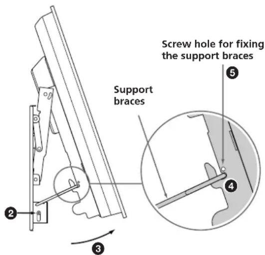
4 Confirm the two support braces of the Plate Unit are locked into the bottom left and right hooks on either side of the Mounting Rack.
5 Insert the screws removed in step ② into the screw holes on the outer sides of the bottom left and right hooks of the Mounting Rack and tighten firmly to lock the support braces.
text_image
Screw hole for fixing the support braces Support braces ⑤ ④ ③2 Connect external equipment cables to the TV.
3 Restore the TV to the non-tilted position.
① Unfasten the screws tightened at the outer sides of the bottom left and right hooks of the Mounting Rack in step ⑤ of procedure 1.
2 Hold the bottom left and right of the TV and pull it out toward you so that the support braces are unlocked from the bottom hooks on the Mounting Rack.
Notes
- Do not hold the transparent part of the TV. - Do not let go of the TV while lifting it, otherwise the TV may hit the wall and cause damage.
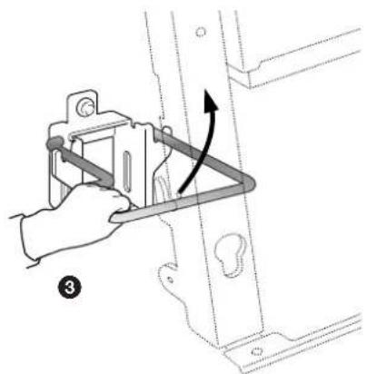
3 Grasp the protruding part of the support braces with your other hand and slide it upward so that the support braces and the TV are restored in the untilted position.
4 Tighten the securing screws. 5 Confirm that all the cables connected to the TV are not twisted or pinched, and then plug in the mains lead.
WARNING
- Be sure two or more people do this work. - Be careful not to pinch your hands or fingers.
natural_image
Illustration of a hand using a tool to adjust or install a metal bracket, with an arrow indicating rotation (no text or symbols present)Specifications
Unit: mm (inches)
Weight: 15.0 kg (33 lb 1 oz)
Design and specifications are subject to change without notice.
PLATE UNIT
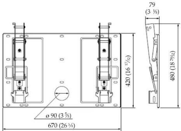
text_image
ø 90 (3 5/8) 670 (26 3/8) 420 (16 17/12) 79 (3 1/8) 480 (18 29/2)MOUNTING RACK
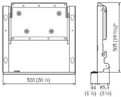
text_image
520 (20 ½) 44 (1 ¾) 85.5 (3 ¾) 505 (19 ¾/²)** When changing the position of the woofer speaker for installing a 50-inch TV: 590 (23 ^1 /4)
SPEAKER
| Speaker unit 10 | cm (2) |
| Impedance 4 Ω | |
| Max. power 50 | W |
TV installing dimensions table
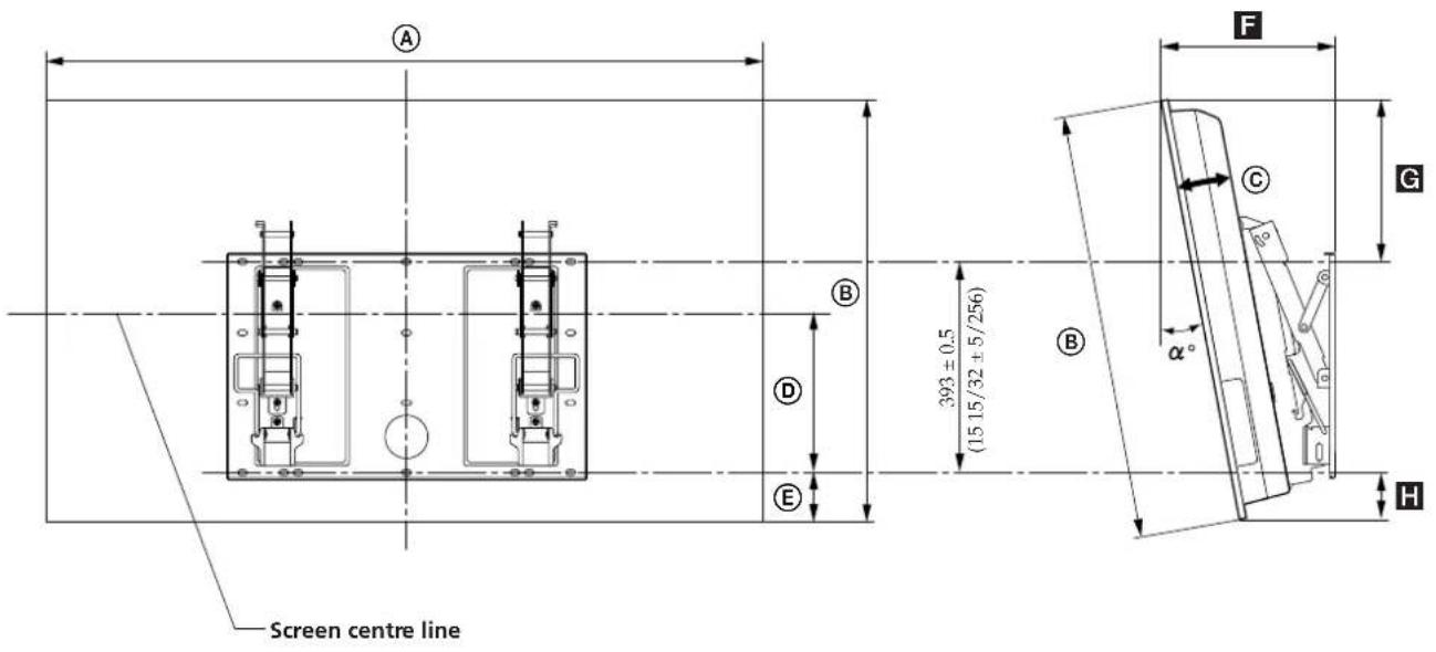
text_image
Screen centre line 393 ± 0.5 (15 15/32 ± 5/256) α° B D E F G C H| TV Model | TV Dimensions | Unit: mm (inches) | Length for each mounting angle | Unit: mm (inches) | Weight | ||||||
| A | B | C | D | E | Mounting angle ( ^ ) | F | G | H | Weight | ( × 4)* | |
| KDE-W50A12U KE-W50A10E | 336 789 89 34(52 5/8) | 43 56(31 1/16) | (3 1/2) | (13 1/2) | (2 7/32) | 0^ 185 (7 | 5/16) 340 (13 13 | /32) 56 (2 7/32) | 52 kg114lb 11oz | 208 kg458lb 9oz | |
| 5^ | 245 (9 21/32) | 327 (12 7/8) 66 (2 | 5/8) | ||||||||
| 10^ | 303 (11 15/16) | 310 (12 7/32) | 74 (2 15/16) | ||||||||
| 15^ | 359 (14 5/32) | 291 (11 15/32) | 80 (3 5/32) | ||||||||
| 20^ | 412 (16 1/4) | 268 (10 9/16) | 83 (3 9/32) | ||||||||
* The wall that the TV will be installed on should be capable of supporting a weight of at least four times that of the TV.
CAUTION
This Wall-Mount Bracket is designed for use with the specified products above.
For other TVs, refer to their operating instructions to check if this Wall-Mount Bracket can be used.
Some TVs are supplied with a leaflet including the TV installing dimensions table ("Installing the Wall-Mount Bracket").
Unit: mm (inches)
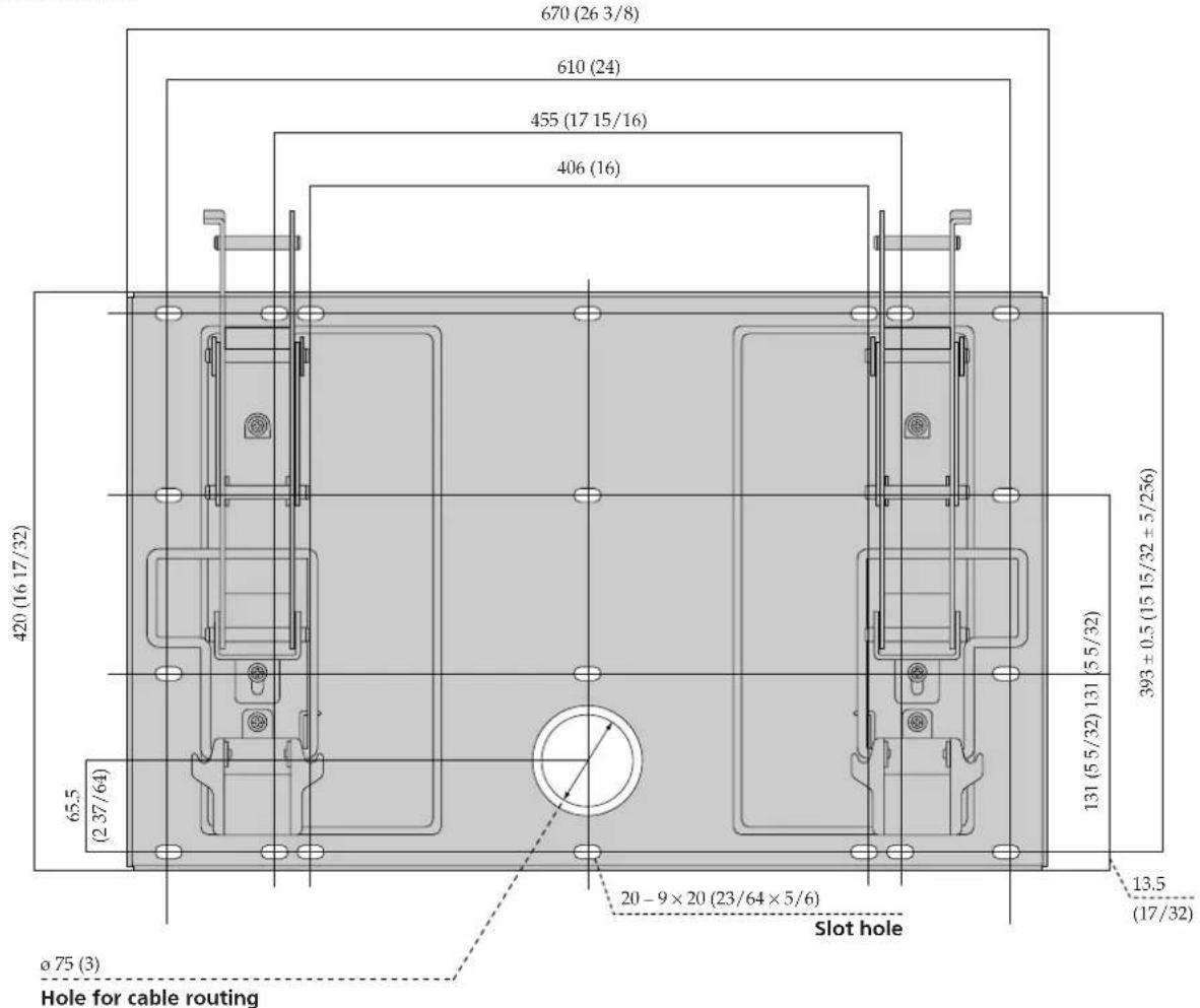
text_image
670 (26 3/8) 610 (24) 455 (17 15/16) 406 (16) 420 (16 17/32) 65.5 (2 37/64) 393 ± 0.5 (15 15/32 ± 5/256) 131 (5 5/32) 131 13.5 (17/32) 20 - 9 × 20 (23/64 × 5/6) Slot hole ø 75 (3) Hole for cable routingnatural_image
Symbol of a trash bin crossed with no text or labels, accompanied by a solid black rectangle below (no text or symbols present)natural_image
Cartoon illustration of a person running away from behind a large rectangular frame with falling beams (no text or symbols)natural_image
Illustration of a person using a tool on a cutting board with stars indicating motion (no text or symbols)natural_image
Simple line drawing of a steaming container with a lid (no text or symbols)natural_image
Illustration of a jacket hanging on a stand next to a blank display board with a small bear (no text or symbols)natural_image
Cartoon illustration of a person reacting with a device to screen, no text or symbols presentnatural_image
Technical line drawing of a mechanical assembly with no visible text or symbolsnatural_image
Simple line drawing of a robotic arm connecting a monitor to a cable (no text or symbols)natural_image
Technical line drawing of a mechanical assembly with two views (front and side), no text or symbols present.Montageplatte (1)
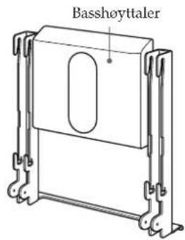
Tieftonlautsprecher

natural_image
Technical line drawing of a mechanical housing or enclosure with mounting brackets (no text or symbols)Montagegestell (1)

Haken (4)
natural_image
Two silhouettes of two people assembling or adjusting a mechanical component (no text or symbols visible)natural_image
Technical line drawing of a mechanical lifting device with two numbered components (1 and 2), no text or symbols present.natural_image
Line drawing of two people holding a large screen mounted on a stand, with arrows indicating upward motion (no text or symbols)Hinweis
text_image
Diagram showing a device with multiple screwdrivers and a magnified view of the component being adjusted.Hinweise
natural_image
Line drawing of two people installing or maintaining a large panel inside a wall-mounted device (no text or symbols visible)Hinweis
natural_image
Illustration of a hand using a mechanical clamp to adjust or install a metal bracket (no text or symbols present)Technische Daten
Einheit: mm
Gewicht: 15,0 kg
natural_image
Symbol of a trash bin crossed out by two diagonal lines (no text or numbers present)natural_image
Cartoon illustration of a person falling from behind a large rectangular frame with a torn edge, no text or symbols presentnatural_image
Illustration of a person using a tool to adjust or install a mechanical component with stars and tools (no text or symbols)natural_image
Simple line drawing of a steaming container with steam rising from top (no text or symbols)natural_image
Illustration of a jacket hanging on a stand next to a blank display board with a teddy bear (no text or symbols)natural_image
Cartoon illustration of a person reacting with a lightning bolt to test a wall-mounted device (no text or symbols present)natural_image
Technical line drawing of a mechanical assembly with no visible text or symbolsnatural_image
Simple line drawing of a hand holding a computer monitor connected to a cable (no text or symbols)natural_image
Technical line drawing of a mechanical assembly with mounting brackets and a central circular component (no text or symbols)Plaat (1)
Woofer-luidspreker
natural_image
Technical line drawing of a mechanical frame or enclosure with mounting feet (no text or symbols)Montagerek (1)

Haak (4)
natural_image
Two silhouettes of people installing or adjusting a device panel (no text or symbols visible)natural_image
Technical line drawing of a mechanical lifting device with two numbered components (1 and 2), no text or symbols present.natural_image
Line drawing of two people holding a large monitor with an upward arrow, mounted on a stand (no text or symbols)Opmerking
text_image
Diagram showing a device with multiple screw holes and a magnified view of the main components, including a close-up of the top component.Opmerkingen
natural_image
Pure technical line drawing of a mechanical assembly without any text, numbers, or symbols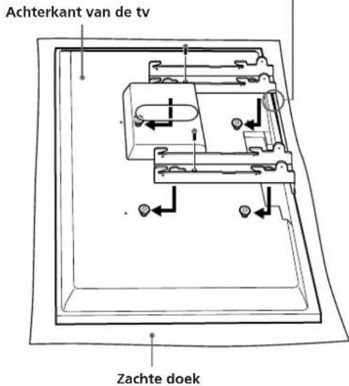
natural_image
Illustration of two silhouetted figures holding a large rectangular panel, with an inset showing a mechanical assembly (no text or symbols)Opmerking
natural_image
Illustration of a hand using a tool to adjust or install a metal bracket, with an arrow indicating rotation (no text or symbols present)Technische gegevens
Eenheid: mm
Gewicht: 15,0 kg
natural_image
Symbol of a trash bin crossed out by two crossed lines (no text or numbers present)natural_image
Cartoon illustration of a person falling from behind a large rectangular frame with a torn edge, no text or symbols presentnatural_image
Illustration of a person using a tool to cut or mark a mechanical component with stars and arrows (no text or symbols)natural_image
Simple line drawing of a steaming container with lid and side panel (no text or symbols)natural_image
Illustration of a suit hanging on a screen with a teddy bear nearby (no text or symbols)natural_image
Cartoon illustration of a person reacting with a ringing alarm clock (no text or symbols)natural_image
Technical line drawing of a mechanical assembly with no visible text or symbolsnatural_image
Simple line drawing of a hand holding a computer monitor connected to a cable (no text or symbols)natural_image
Technical line drawing of a mechanical assembly with two views (front and side), no text or symbols present.Placa (1)
text_image
Woofer
Parafuso (+PSW5 × L14) (6)
natural_image
Two silhouettes of two people assembling or adjusting a mechanical component (no text or symbols visible)natural_image
Technical line drawing of a mechanical lifting device with two numbered components (1 and 2), no text or symbols present.natural_image
Line drawing of two people holding a large monitor with upward arrows indicating motion (no text or symbols)Nota
text_image
Diagram showing a device with multiple screw fasteners and a magnified view of the next two components, including a close-up of the top component.Notas
natural_image
Illustration of two silhouetted figures holding a large rectangular panel, with an inset showing a mechanical assembly (no text or symbols)Nota
natural_image
Illustration of a hand using a tool to adjust or install a metal bracket, with an arrow indicating rotation (no text or symbols present)natural_image
Symbol of a trash bin crossed out by a diagonal line, representing no waste or discharge (no text or labels)natural_image
Cartoon illustration of a person running toward a large rectangular frame with a torn edge, indicating shock or collapse (no text or symbols present)natural_image
Illustration of a person using a tool to cut or adjust a mechanical component with stars and arrows (no text or symbols)natural_image
Simple line drawing of a steaming container with lid and side panel (no text or symbols)natural_image
Illustration of a suit hanging on a stand next to a blank display board with a teddy bear (no text or symbols)natural_image
Cartoon illustration of a person reacting with a large screen, no text or symbols presentnatural_image
Technical line drawing of a mechanical assembly with no visible text or symbolsnatural_image
Simple line drawing of a hand holding a computer monitor connected to a cable (no text or symbols)natural_image
Technical line drawing of a mechanical assembly with two views (front and side), no text or symbols present.Plate (1)
natural_image
Two silhouettes of people installing or adjusting a wall-mounted device (no text or symbols visible)text_image
Technical diagram of a mechanical lifting device with labeled parts 1 and 2natural_image
Line drawing of two people holding a large monitor with an upward arrow, mounted on a stand (no text or symbols)Merknad
text_image
Diagram showing a device with multiple screwdrivers and a magnified view of the component being adjusted.Merk
- Hvis du bruker en elektrisk skrutrekker, må du sette dreiemomentet til omtrent 2 N·m.
- Ikke la TV-apparatet ligge med fremsiden ned over en lengre periode, da dette kan skade overflaten.
Trinn 5: Montere TV-apparatet
ADVARSEL
natural_image
Illustration of two figures installing or maintaining a large rectangular panel, with an inset showing a mechanical assembly (no text or symbols)Merknad
natural_image
Illustration of a hand using a tool to adjust or install a metal bracket, with an arrow indicating rotation (no text or symbols present)Spesifikasjoner
Enhet: mm (tommer)
Vekt: 15,0 kg (33 lb 1 oz)
natural_image
Symbol of a trash bin crossed out by two crossed lines (no text or labels)natural_image
Cartoon illustration of a person reacting to a large screen with a falling object (no text or symbols)natural_image
Illustration of a person using a tool to interact with a machine (no text or symbols visible)natural_image
Simple line drawing of a steaming container with lid and handle (no text or symbols)natural_image
Illustration of a jacket hanging on a screen with a teddy bear on top (no text or symbols)natural_image
Cartoon illustration of a person reacting to a wall-mounted screen with cables, no text or symbols presentnatural_image
Technical line drawing of a mechanical assembly with no visible text or symbolsnatural_image
Simple line drawing of a robotic arm connecting a monitor to a cable (no text or symbols)natural_image
Technical line drawing of a mechanical assembly with two views (front and side), no text or symbols present.Plaque (1)
natural_image
Two silhouettes of two people standing in front of a device panel, no text or symbols visiblenatural_image
Technical line drawing of a mechanical lifting or bracket assembly (no text or symbols)natural_image
Line drawing of two people holding a large monitor with upward arrows indicating motion (no text or symbols)Remarque
text_image
Diagram showing a device with multiple screw fasteners and a magnified view of the next three components, including a close-up of the top two parts.Remarques
text_image
Vis (+B6 × L20, fournies)natural_image
Illustration of two people installing a large panel mounted on a wall, with an inset showing a mechanical assembly (no text or symbols present)Remarque
natural_image
Illustration of a hand using a clamp to adjust or install a metal bracket, with an arrow indicating rotation (no text or symbols present)Spécifications
natural_image
Symbol of a trash bin crossed out by two diagonal lines (no text or numbers present)natural_image
Cartoon illustration of a person reacting to a large screen collapse (no text or symbols)natural_image
Illustration of a person using a power tool to cut a saw (no text or symbols present)natural_image
Simple line drawing of a steaming container with lid and handle (no text or symbols)natural_image
Illustration of a jacket hanging on a screen with a teddy bear nearby (no text or symbols)natural_image
Cartoon illustration of a person reacting with a lightning bolt to strike a large screen (no text or symbols present)natural_image
Technical line drawing of a mechanical assembly with no visible text or symbolsnatural_image
Simple line drawing of a robotic arm connecting a monitor to a cable (no text or symbols)natural_image
Technical line drawing of a mechanical assembly with two views (front and side), no text or symbols present.Piastra (1)
text_image
Altoparlante wootext_image
300 (11 1/3/6) 100 (3/5/6) 100 (3/5/6) 100 (3/5/6)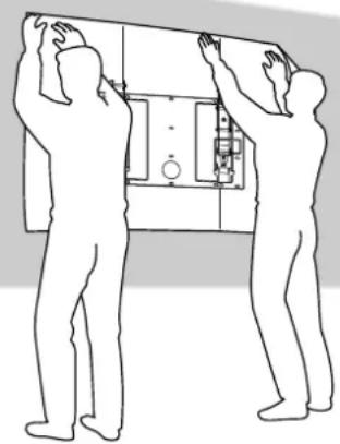
natural_image
Two silhouettes of people installing or adjusting a device panel (no text or symbols visible)natural_image
Technical line drawing of a dual-chamber electrical enclosure or enclosure with mounting brackets and wiring (no text or symbols)Piastra